Work Mode Indicator and Power Converter for Lamp
Abstract
The present disclosure relates to A work mode indicator for a lamp, including: a user command switch unit configured to issue a switch command to switch a work mode; a controller configured to output a work mode indication control signal, the controller being electrically connected to the user command switch unit; and a work mode indication unit; wherein the work mode indication unit is a multicolor light-emitting indicator lamp configured to emit multiple colors of light to indicate different work modes, and the controller has an output end electrically connected to the multicolor light-emitting indicator lamp. With the present disclosure, different work modes of the lamp may be indicated through a multicolor light-emitting indicator lamp, whereby a user can determine which work mode the lamp is in.
Claims (8)
1. A work mode indicator for a lamp, comprising: a user command switch unit configured to issue a switch command to switch a work mode; a controller (U 2 ) configured to output a work mode indication control signal, the controller (U 2 ) being electrically connected to the user command switch unit; and a work mode indication unit; wherein the work mode indication unit is a multicolor light-emitting indicator lamp ( 1 ) configured to emit multiple colors of light to indicate different work modes, and the controller (U 2 ) has an output end electrically connected to the multicolor light-emitting indicator lamp ( 1 ); wherein the work mode indication control signal output by the controller ( 2 ) is a PWM signal, the multicolor light-emitting indicator lamp ( 1 ) is a light-emitting hybrid encapsulated component, and the output end of the controller ( 2 ) is electrically connected to the light-emitting hybrid encapsulated component; wherein the light-emitting hybrid encapsulated component comprises: a first light-emitting diode (LED 1 ) having an anode terminal electrically connected to a first output end of the controller (U 2 ); and a second light-emitting diode (LED 2 ) having an anode terminal electrically connected to a second output end of the controller (U 2 ); the second light-emitting diode (LED 2 ) being encapsulated into one piece with the first light-emitting diode (LED 1 ); and cathode terminals of the first light-emitting diode (LED 1 ) and the second light-emitting diode (LED 2 ) being connected.
Show 7 dependent claims
2. The work mode indicator for the lamp according to claim 1 , wherein the work mode indication control signal output by the controller ( 2 ) is a coded signal, the multicolor light-emitting indicator lamp ( 1 ) is a coded light-emitting module, and the controller (U 2 ) is electrically connected to the coded light-emitting module.
3. The work mode indicator for the lamp according to claim 2 , wherein the coded light-emitting module comprises: a control chip configured to output a PWM signal according to a coded signal, the control chip being electrically connected to the controller (U 2 ); and a light-emitting hybrid encapsulated component electrically connected to an output end of the control chip, the light-emitting hybrid encapsulated component being composed of multiple light-emitting diodes that emit different colors of light, and these light-emitting diodes being encapsulated into one piece with the control chip.
4. A power converter for a lamp, comprising a shell ( 2 ), a PCB board ( 3 ) and a waterproof component ( 4 ), the PCB board ( 3 ) being positioned inside the shell ( 2 ), the shell ( 2 ) being formed with a hole, and the waterproof component ( 4 ) being mated with the hole, wherein the power converter further comprises the work mode indicator for the lamp according to claim 1 , the user command switch unit, the controller (U 2 ) and the multicolor light-emitting indicator lamp in the work mode indicator are all arranged on the PCB board ( 3 ), the waterproof component ( 4 ) is made of a transparent material, the user command switch unit is a changeover switch (SW 1 ) and/or a radio signal receiving module, the multicolor light-emitting indicator lamp ( 1 ) and the changeover switch (SW 1 ) are mated with the waterproof component ( 4 ) respectively, wherein the work mode indication control signal output by the controller ( 2 ) is a PWM signal, the multicolor light-emitting indicator lamp ( 1 ) is a light-emitting hybrid encapsulated component, and the output end of the controller ( 2 ) is electrically connected to the light-emitting hybrid encapsulated component; and wherein the light-emitting hybrid encapsulated component comprises: a first light-emitting diode (LED 1 ) having an anode terminal electrically connected to a first output end of the controller (U 2 ); and a second light-emitting diode (LED 2 ) having an anode terminal electrically connected to a second output end of the controller (U 2 ); the second light-emitting diode (LED 2 ) being encapsulated into one piece with the first light-emitting diode (LED 1 ); and cathode terminals of the first light-emitting diode (LED 1 ) and the second light-emitting diode (LED 2 ) being connected.
5. The power converter for the lamp according to claim 4 , wherein the user command switch unit further comprises a microphone (MI) configured to acquire a user voice switch command; the power converter further comprises: an offline voice recognition unit ( 5 ) having an input end electrically connected to the microphone (MI); after directly parsing a voice switch command provided by the microphone (MI), the offline voice recognition unit ( 5 ) outputting a work mode control command matched with the input voice switch command; the controller (U 2 ) being electrically connected to an output end of the offline voice recognition unit ( 5 ) to acquire the work mode control command; and the changeover switch (SW 1 ) or the radio signal receiving module being further configured to switch between a manual control mode and a voice control mode.
6. The power converter for the lamp according to claim 5 , wherein the offline voice recognition unit ( 5 ) comprises: an offline voice recognition chip (U 1 ) configured to parse the voice switch command and output a command signal, the offline voice recognition chip (U 1 ) being electrically connected to the microphone (MI), and the offline voice recognition chip (U 1 ) being inbuilt with a module configured to generate the work mode control command.
7. The power converter for a lamp of claim 4 , wherein the work mode indication control signal output by the controller ( 2 ) is a coded signal, the multicolor light-emitting indicator lamp ( 1 ) is a coded light-emitting module, and the controller (U 2 ) is electrically connected to the coded light-emitting module.
8. The power converter for a lamp of claim 7 , wherein the coded light-emitting module comprises: a control chip configured to output a PWM signal according to a coded signal, the control chip being electrically connected to the controller (U 2 ); and a light-emitting hybrid encapsulated component electrically connected to an output end of the control chip, the light-emitting hybrid encapsulated component being composed of multiple light-emitting diodes that emit different colors of light, and these light-emitting diodes being encapsulated into one piece with the control chip.
Full Description
Show full text →
CROSS-REFERENCE TO RELATED APPLICATION
This application claims priority from the Chinese patent application 2022231066611 filed Nov. 23, 2022, the content of which is incorporated herein in the entirety by reference.
TECHNICAL FIELD
The present disclosure relates to a work mode indicator and a power converter for a lamp.
BACKGROUND
LED lamps have very wide market and application prospects, with advantages of high illumination efficiency, long service life, low driving voltage, quick response speed and low power consumption. With the development of science and technology, LED illumination is gradually replacing traditional filament lamps due to its advantages of energy conservation, long service life, colorful lighting and the like. In addition, there is also increasing research on LED lighting equipment both domestically and abroad. With the development of the LED illumination field, people are more and more inclined to intelligent illumination equipment.
For example, LED lamp strings used during festivals, which usually are wound around a tree or column, or arranged in other forms. Since the LED lamp string has a low working voltage, a power converter is needed to covert a high-voltage alternating current into a 5V low voltage to supply to the LED lamp string
In the prior art, there have been patents which disclosed the above power converter. The power converter, besides supplying power, also plays a role of controlling a work mode of the LED lamp string. For example, by outputting control signals of different duty ratios, the flickering speed and frequency and the like of the LED lamp string are controlled.
The above power converter generally has a function of controlling the LED lamp string to operate in a timing manner. For example, after the timing mode is enabled, the LED lamp string is controlled to light off during daytime and light on during nighttime. To facilitate people to identify the timing work mode, one timing indicator lamp is arranged inside the existing power converters, generally, it is one light-emitting diode (LED). When the timing mode is enabled, the indicator lamp is on; when the timing mode is disabled, the indicator lamp is off.
However, with the function diversification of the power converter, a single-function timing indicator lamp cannot meet the requirements of users when indicating whether it is in a timing work mode. For example, some users point out that there are several timing modes after the timing work mode is enabled. For example, a first mode: 18 hours On and 6 hours Off; a second mode: 16 hours On and 8 hours Off; a third mode: 6 hours On, 6 hours Off, 3 hours On and 9 hours Off. Obviously, in the multiple timing modes, when observing the timing indicator lamp, the user just knows it is in a timing work mode. The LED that emits one color of light cannot allow the user to distinguish which timing mode is selected. Thus, the existing structures have deficiencies that could confuse the users.
SUMMARY
The present disclosure aims to provide a work mode indicator and a power converter for a lamp. With the present disclosure, different work modes of the lamp may be indicated through a multicolor light-emitting indicator lamp, whereby a user can determine which work mode the lamp is in.
A work mode indicator for a lamp, comprising: a user command switch unit configured to issue a switch command to switch a work mode; a controller configured to output a work mode indication control signal, the controller being electrically connected to the user command switch unit; and a work mode indication unit; wherein the work mode indication unit is a multicolor light-emitting indicator lamp configured to emit multiple colors of light to indicate different work modes, and the controller has an output end electrically connected to the multicolor light-emitting indicator lamp.
The work mode of the lamp may be selected through a user command switch unit. The work mode of the lamp generally includes a standby mode, a lighting work mode and a timing work mode. In the standby mode, the multicolor light-emitting indicator lamp emits a light of color D 1 . In the lighting work mode, the multicolor light-emitting indicator lamp emits a light of color D 2 . After entering the timing work mode, since there are multiple timing modes, the multicolor light-emitting indicator lamp emits a light of color D 3 to indicate a first timing mode when entering the timing work mode at first. When switching a timing mode in the timing work mode, the multicolor light-emitting indicator lamp emits a light of color D 4 to indicate a second timing mode, and the multicolor light-emitting indicator lamp emits a light of color D 5 to indicate a third timing mode. With the present disclosure, different work modes of the lamp may be indicated through a multicolor light-emitting indicator lamp, whereby a user can determine which work mode the lamp is in.
BRIEF DESCRIPTION OF THE DRAWINGS
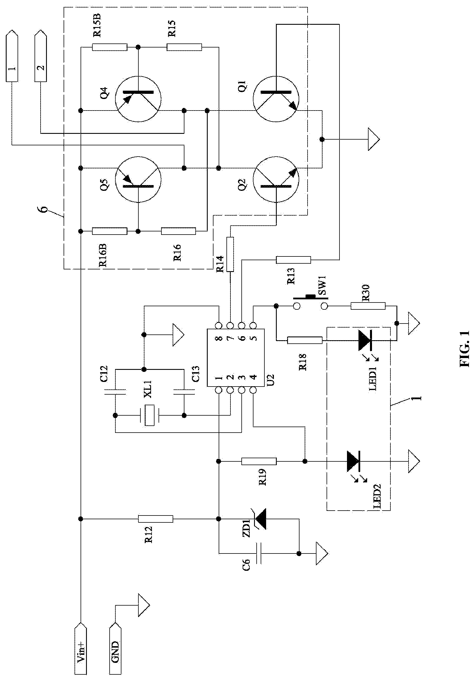
is a circuit diagram of an indicator of a first work mode.
is a circuit diagram of an indicator of a second work mode.
is an exploded view of a power converter formed by assembling a work mode indicator for a lamp according to the present disclosure and a circuit board and a shell.
is a rear view of the power converter shown in .
is a circuit diagram of an indicator of a third work mode which is arranged inside a power converter.
is a diagram of a first American standard power converter acquired after the application of the present disclosure.
is a diagram of a first European standard power converter acquired after the application of the present disclosure.
is a diagram of a first British standard power converter acquired after the application of the present disclosure.
is a diagram of a first Australian standard power converter acquired after the application of the present disclosure.
is a diagram of a first separate power converter acquired after the application of the present disclosure.
is a diagram of a second American standard power converter acquired after the application of the present disclosure.
is a diagram of a second European standard power converter acquired after the application of the present disclosure.
is a diagram of a second British standard power converter acquired after the application of the present disclosure.
is a diagram of a second Australian standard power converter acquired after the application of the present disclosure.
is a diagram of a second separate power converter acquired after the application of the present disclosure.
DETAILED DESCRIPTION OF THE EMBODIMENTS
Embodiment 1
As shown in , a work mode indicator for a lamp provided by the present disclosure includes a user command switch unit, a controller U 2 and a work mode indication unit. Herein below are described in detail each part and the relationship between each part.
The user command switch unit is configured to issue a switch command to switch a work mode. The controller U 2 is configured to output a work mode indication control signal, and the controller U 2 is electrically connected to the user command switch unit. By means of a work mode switch command sent to the controller U 2 by the user command switch unit, the work mode of the lamp may be selected.
As shown in , in the present embodiment, the user command switch unit preferably employs a changeover switch SW 1 , the controller U 2 preferably employs a programmable single-chip. Different work mode switch commands may be provided to the controller U 2 by detecting a conduction time of the changeover switch SW 1 or a number of times of pressing within a specified time. For example:
As shown in , leave the changeover switch SW 1 conducted for 3 consecutive seconds, then the controller U 2 outputs a command signal to allow the lamp into a timing work mode. After entering the timing work mode, a default first timing mode is enabled at first, that is, a timing mode of 18 hours ON and 6 hours Off. In the timing work mode, press the changeover switch SW 1 for two consecutive times within 1 second to switch into another timing work mode. For example, in the default first timing mode, press the changeover switch SW 1 for two consecutive times within 1 second to switch into a second timing work mode, that is, 16 hours ON and 8 hours Off. Through such operations, switch may be carried out between multiple timing modes. If to exit the timing mode, just leave the changeover switch SW 1 conducted for 3 consecutive seconds again.
As shown in , the work mode indication unit is a multicolor light-emitting indicator lamp 1 configured to emit multiple colors of light to indicate different work modes, and the controller U 2 has an output end electrically connected to the multicolor light-emitting indicator lamp 1 . In the present embodiment, for different work modes, the controller U 2 outputs different work mode indication control signals to the multicolor light-emitting indicator lamp 1 , so that the multicolor light-emitting indicator lamp 1 emits different colors of light.
As shown in , the work mode of the lamp generally includes a standby mode, a lighting work mode (in which mode, the LED lamp string is enabled to have multiple modes of lighting), and a timing work mode. For example, in the standby mode, the multicolor light-emitting indicator lamp 1 emits a light of color D 1 . In the lighting work mode, the multicolor light-emitting indicator lamp 1 emits a light of color D 2 . In the lighting work mode, there are multiple modes to light. Since the LED lamp string has already lighted, it is possible to identify which lighting mode is in use through the lighting status of the LED lamp string. Therefore, it is no longer necessary to indicate the lighting mode of the LED lamp string through the multicolor light-emitting indicator lamp 1 . After entering the timing work mode, since there are multiple timing modes, the multicolor light-emitting indicator lamp 1 emits a light of color D 3 to indicate a first timing mode when entering the timing work mode at first. When switching a timing mode in the timing work mode, the multicolor light-emitting indicator lamp 1 emits a light of color D 4 to indicate a second timing mode, and the multicolor light-emitting indicator lamp 1 emits a light of color D 5 to indicate a third timing mode. When the multicolor light-emitting indicator lamp 1 emits a light of color D 1 or D 2 , it means the lamp has exited the timing work mode. Through the above description, the multicolor light-emitting indicator lamp 1 not only can indicate the multiple work modes, but also can indicate the specific timing modes.
As shown in , the work mode indication control signal output by the controller 2 is a PWM signal, the multicolor light-emitting indicator lamp 1 is a light-emitting hybrid encapsulated component, and the output end of the controller 2 is electrically connected to the light-emitting hybrid encapsulated component.
As shown in , the light-emitting hybrid encapsulated component includes a first Light-emitting diode LED 1 and a second Light-emitting diode LED 2 . The first Light-emitting diode LED 1 has an anode terminal electrically connected to a first output end of the controller U 2 ; the second Light-emitting diode LED 2 has an anode terminal electrically connected to a second output end of the controller U 2 ; the second Light-emitting diode LED 2 is encapsulated into one piece with the first Light-emitting diode LED 1 ; and cathode terminals of the first Light-emitting diode LED 1 and the second Light-emitting diode LED 2 are connected.
As shown in , the PWM signal output by the controller U 2 is employed to control a duty ratio of the first Light-emitting diode LED 1 to the second Light-emitting diode LED 2 , so that the first Light-emitting diode LED 1 or the second Light-emitting diode LED 2 emits light separately, or the first Light-emitting diode LED 1 and the second Light-emitting diode LED 2 emit light at the same time. A mixed light is generated when they emit light at the same time. Since the duty ratio is different, the generated mixed light is of different colors, thereby obtaining the above D 1 to D 5 colors.
As shown in , the work mode indicator further includes a current limit resistor R 18 , the anode terminal of the first Light-emitting diode LED 1 is electrically connected to the first output end of the controller U 2 through the current limit resistor R 18 ; the cathode terminal of the first Light-emitting diode LED 1 and the cathode terminal of the second Light-emitting diode LED 2 are grounded.
Embodiment 2
As shown in , the present embodiment is different from the Embodiment 1 in that: the work mode indication control signal output by the controller U 2 is a coded signal, the multicolor light-emitting indicator lamp 1 is a coded light-emitting module, and the controller U 2 is electrically connected to the coded light-emitting module. When the controller U 2 receives a work mode switch command input from the user command switch unit, the controller U 2 outputs a coded signal and provides it to the coded light-emitting module, then the coded light-emitting module parses the coded signal.
As shown in , the coded light-emitting module includes a control chip and a light-emitting hybrid encapsulated component. The control chip is configured to output a PWM signal according to a coded signal, the control chip is electrically connected to the controller U 2 , the light-emitting hybrid encapsulated component is electrically connected to an output end of the control chip, the light-emitting hybrid encapsulated component is composed of multiple light-emitting diodes that emit different colors of light, and these light-emitting diodes are encapsulated into one piece with the control chip.
As shown in , the control chip parses the coded signal and then outputs a PWM signal. Each code corresponds to one PWM signal. The control chip is inbuilt with multiple light-emitting control programs. After parsing the coded signal, the control chip calls a light-emitting control program matched with the coded signal to control the duty ratio of the multiple light-emitting diodes inside the light-emitting hybrid encapsulated component, so that the light-emitting hybrid encapsulated component emits different colors of light.
As shown in , there are three light-emitting diodes that emit different colors of light. A first one can emit red light separately, a second one can emit green light separately, and a third one can emit blue light separately. By controlling different duty ratios of each light-emitting diode, the light-emitting hybrid encapsulated component can emit different colors of light.
Embodiment 3
The present embodiment is different from the Embodiment 1 in that: the user command switch unit employs a radio signal receiving module. The radio signal receiving module may be an infrared signal receiving module, a Bluetooth receiving module, a WIFI receiving module, etc. A work mode switch command is sent to the radio signal receiving module through a radio signal transmitting module. For example, a work mode switch command is sent to the infrared signal receiving module through an infrared signal remote controller, or a work mode switch command is sent to the Bluetooth receiving module through a Bluetooth device, or a work mode switch command is sent to the WIFI receiving module through a WIFI device. The infrared signal remote controller and/or the Bluetooth device and/or the WIFI device may be integrated into a mobile device, for example, a smart phone.
A power converter A for a lamp may be obtained by application of any one of the work mode indicators for the lamp in the above Embodiment 1 to Embodiment 3. Below are described specific embodiments of several power converters A for lamps.
Embodiment 1 of a Power Converter A for a Lamp
As shown in to , a power converter A for a lamp includes a shell 2 , a PCB board 3 , a waterproof component 4 and a work mode indicator for the lamp. The PCB board 3 is positioned inside the shell 2 , the shell 2 is formed with a hole, and the waterproof component 4 is mated with the hole. The user command switch unit, the controller U 2 and the multicolor light-emitting indicator lamp in the work mode indicator are all arranged on the PCB board 3 , for example, they are fixed onto the PCB board 3 through welding. The waterproof component 4 is made of a transparent material. The waterproof component 4 preferably employs silicone. Since the user command switch unit is a changeover switch SW 1 and/or a radio signal receiving module, in the present embodiment the multicolor light-emitting indicator lamp 1 and the changeover switch SW 1 are mated with the waterproof component 4 respectively.
As shown in to , in the present embodiment, by means of the transparency of the waterproof component 4 , the light emitted by the multicolor light-emitting indicator lamp 1 can pass through the waterproof component 4 , so that a user can observe the lighting color of the multicolor light-emitting indicator lamp 1 and then determine the current work mode of the power converter A. In addition, the changeover switch SW 1 is mated with the waterproof component 4 ; if a pressure is applied to the waterproof component 4 , the waterproof component 4 will transfer the pressure to the changeover switch SW 1 , so that the changeover switch SW 1 sends a work mode switch command to the controller U 2 . The waterproof component 4 achieves multiple functions.
As shown in to , the user command switch unit further includes a microphone MI configured to acquire a user voice switch command. The power converter A further includes an offline voice recognition unit 5 . The offline voice recognition unit 5 has an input end electrically connected to the microphone MI. After directly parsing a voice switch command provided by the microphone MI, the offline voice recognition unit 5 outputs a work mode control command matched with the input voice switch command. The controller U 2 is electrically connected to an output end of the offline voice recognition unit 5 to acquire the work mode control command. The switch SW 1 is further configured to switch between a manual control mode and a voice control mode.
The microphone MI may be installed on the shell 2 (as shown in ). A small hole is formed on the shell 2 , and voice is transmitted to the microphone MI through the small hole. Sealing adhesive is provided between the microphone MI and the shell 2 , to prevent water entering the shell. In addition, the microphone MI may also be installed on the circuit board, and the small hole formed on the shell 2 is not sealed by sealing adhesive. Such structure is applicable to indoor use.
As shown in to , the microphone MI is configured to acquire a user voice switch command. The user voice switch command is to switch the work modes of the lamp, including On/Off, brightness, color (red light, white light, green light, etc.), flickering frequency, lamp on timing and lamp off timing.
As shown in to , the input end of the offline voice recognition unit 5 is electrically connected to the microphone MI. The offline voice recognition unit 5 may be electrically connected to the microphone MI through a wired or wireless mode. The wired mode employs welding, and the wireless mode employs Bluetooth or WIFI, etc.
As shown in to , after directly parsing the voice switch command provided by the microphone MI, the offline voice recognition unit 5 outputs a work mode control command matched with the input voice switch command. The offline voice recognition unit 5 is capable of recognizing voice without accessing a network.
As shown in to , in the present embodiment, the offline voice recognition unit 5 includes: an offline voice recognition chip U 1 electrically connected to the microphone MI. The offline voice recognition chip U 1 is configured to parse a voice switch command and output a command signal. The controller U 2 is electrically connected to the offline voice recognition chip U 1 , and the controller U 2 generates a work mode control command after parsing the command signal provided by the offline voice recognition chip U 1 .
As shown in to , the work mode control command is configured to control a standby switch mode, a lighting work mode and a timing work mode of the lamp. The standby switch mode is to control the lamp to enter or exit the standby mode. The lighting work mode includes the brightness, color, flickering mode, flickering frequency and the like of the lamp. The timing work mode includes lamp on timing, lamp off timing and settings of different timing lengths.
As shown in to , the offline voice recognition chip U 1 is inbuilt with a voice parsing program. The command signal output by the offline voice recognition chip U 1 after parsing a voice is a string of codes. Different codes are indicative of different work modes. The controller U 2 has stored therein multiple control programs. After receiving a corresponding code, the controller U 2 calls a control program matched with the code, so that the control program generates a work mode control command.
For example, a voice switch command issued by a user is to allow the LED lamp string to light with the highest brightness, the microphone MI acquires a command to emit red light and then transmits the command to the offline voice recognition chip U 1 . The offline voice recognition chip U 1 parses the voice switch command to light with the highest brightness and then generates a code 001. The controller U 2 calls a first subprogram matched with 001 after receiving the code 001, thus outputting a control command to light with the highest brightness to a drive circuit 6 .
As shown in to , the drive circuit 6 is electrically connected to the output end of the offline voice recognition unit 5 to acquire the work mode control command. In the present embodiment, the first output end of the controller U 2 is connected to the drive circuit 6 through a thirteenth resistor R 13 , and the second output end of the controller U 2 is connected to the drive circuit 6 through a fourteenth resistor R 14 .
The structure of the drive circuit 6 is of existing technologies, and no further description is repeated here. The work mode control command output by the offline voice recognition unit 5 is mainly to control the duty ratio of each transistor in the drive circuit 6 , thereby changing the brightness, color, flickering frequency and the like of the lamp.
As shown in to , after the offline voice recognition unit 5 is added into the power converter A, the power converter A may be switched between the manual control mode and the voice control mode through the changeover switch SW 1 and the radio signal receiving module. For example, press the changeover switch SW 1 for three times within one second to enter the voice control mode from the manual control mode; or, press the changeover switch SW 1 for three times within one second to enter the manual control mode from the voice control mode; or a command to enter the voice control mode is transmitted to the radio signal receiving module through the radio signal transmitting module.
As shown in to , when the power converter A enters the voice control mode, the multicolor light-emitting indicator lamp 1 emits a light of color D 6 . When a user issues a command to enter the voice control mode, if the multicolor light-emitting indicator lamp 1 emits a light of color D 6 , it is indicated that the power converter A enters the voice control mode successfully; otherwise, it fails.
As shown in to , the power converter A further includes a third capacitor C 3 configured to filter a power signal. The third capacitor C 3 is electrically connected to the offline voice recognition unit 5 . In the present embodiment, third capacitor C 3 is electrically connected to the offline voice recognition chip U 1 . The offline voice recognition chip U 1 totally includes sixteen pins, among which a second pin is a power input pin. The offline voice recognition chip U 1 is internally provided with a regulator circuit, which is grounded through a third pin and the third capacitor C 3 . The third capacitor C 3 is configured to filter a power signal of the regulator circuit.
As shown in to , an eleventh pin of the offline voice recognition chip U 1 is a command signal output pin. The eleventh pin of the offline voice recognition chip U 1 is connected to a signal input end of the controller U 2 , that is, connected to a fourth pin of the controller U 2 .
As shown in to , the present embodiment further includes a fourth capacitor C 4 . The fourth capacitor C 4 is electrically connected to the offline voice recognition chip U 1 . The offline voice recognition chip U 1 is internally provided with a power source configured to supply power to the microphone MI. The fourth capacitor C 4 is configured to filter the power supplied to the microphone MI.
As shown in to , the present embodiment further includes a power source. The power source is electrically connected to the offline voice recognition unit 5 . The power source includes: a three terminal regulator U 3 , a first capacitor C 1 and a second capacitor C 2 . The first capacitor C 1 is connected to a power input end of the three terminal regulator U 3 . The second capacitor C 2 is connected to a power output end of the three terminal regulator U 3 . In the present embodiment, the power supplied to the three terminal regulator U 3 is a direct current. For example, a 12V direct current is transmitted to the three terminal regulator U 3 , the input direct current is filtered by the first capacitor C 1 , and the output 5V direct current is filtered by the second capacitor C 2 .
As shown in to , the present embodiment further includes an anti-reverse diode D 1 . The anti-reverse diode D 1 has a cathode terminal connected to an input end of the power source and has an anode terminal grounded.
Embodiment 2 of a Power Converter A for a Lamp
The present embodiment is different from the Embodiment 1 in that: the shell 2 is provided with a transparent area, the user command switch unit is mated with the waterproof component 4 , and the multicolor light-emitting indicator lamp 1 is mated with the transparent area.
Embodiment 3 of a Power Converter A for a Lamp
The present embodiment is different from the Embodiment 1 in that: the shell 2 is provided with a transparent area, the user command switch unit is a radio signal receiving module, the multicolor light-emitting indicator lamp 1 and the radio signal receiving module are mated with the transparent area respectively.
Figures (9)
Citations
This patent cites (5)
- US20170280533
- US20220322506
- US20230345599
- US216414636
- US216959842