Abstract
A solar power generation system includes a string, an inverter, and a first shut-off device. The string includes a plurality of solar cell modules connected in series. The inverter converts DC power output from the plurality of solar cell modules to AC power. The first shut-off device is connected to electrical paths connecting the plurality of solar cell modules to each other. The string includes a plurality of solar cell module groups each including the plurality of the solar cell modules. The plurality of solar cell module groups include at least a first group and a second group connected to the first group. The first shut-off device shuts off a first electrical path connecting the first group and the second group and a second electrical path connecting the plurality of solar cell modules belonging to the first group to each other in response to a control signal from the inverter.
Claims (14)
1. A solar power generation system, comprising: a string including a plurality of solar cell modules connected in series; an inverter connected to the string, the inverter being configured to convert DC power output from the plurality of solar cell modules to AC power; and a first shut-off device connected to electrical paths connecting the plurality of solar cell modules to each other, wherein the string includes a plurality of solar cell module groups each including the plurality of the solar cell modules, the plurality of solar cell module groups include at least a first group and a second group connected to the first group, the electrical paths include a first electrical path connecting the first group and the second group, and a second electrical path connecting the plurality of solar cell modules belonging to the first group to each other, the first shut-off device is configured to shut off the first electrical path and the second electrical path in response to a control signal from the inverter, the first group includes at least a first solar cell module and a second solar cell module among the plurality of the solar cell modules, the first solar cell module being connected the second group, the second solar cell module being connected the first solar cell module, the second group includes a third solar cell module connected to the first solar cell module among the plurality of solar cell modules, the first shut-off device includes a first opening/closing unit configured to open/close a connection between the first solar cell module and the third solar cell module, and a second opening/closing unit configured to open/close a connection between the first solar cell module and the second solar cell module, and the first shut-off device is driven by an electrical power generated by the first solar cell module.
8. A solar power generation system, comprising: a string including a plurality of solar cell modules connected in series; an inverter connected to the string, the inverter being configured to convert DC power output from the plurality of solar cell modules to AC power; a first shut-off device connected to electrical paths connecting the plurality of solar cell modules to each other; and a second shut-off device connected to the electrical paths connecting the plurality of solar cell modules to each other, wherein the string includes a plurality of solar cell module groups each including the plurality of the solar cell modules, the plurality of solar cell module groups include at least a first group and a second group connected to the first group, the electrical paths include a first electrical path connecting the first group and the second group, and a second electrical path connecting the plurality of solar cell modules belonging to the first group to each other, the first shut-off device is configured to shut off the first electrical path and the second electrical path in response to a control signal from the inverter, the plurality of solar cell module groups further include a third group connected to the second group, the electrical paths further include a third electrical path connecting the second group and the third group, and a fourth electrical path connecting the plurality of solar cell modules belonging to the second group to each other, the second shut-off device is configured to shut off the third electrical path and the fourth electrical path in response to the control signal from the inverter, and the first shut-off device and second shut-off device each include a signal receiving unit configured to receive the control signal from the inverter, and a bypass circuit configured to cause the signal receiving unit to receive the control signal from the inverter in a state where the electrical paths connected to the first shut-off device and the electrical paths connected to the second shut-off device are shut off.
Show 12 dependent claims
2. The solar power generation system according to claim 1 , wherein the first opening/closing unit of the first shut-off device is connected to one of a terminal on an anode side or a terminal on a cathode side of the first solar cell module, and the second opening/closing unit of the first shut-off device is connected to another of the terminal on the anode side or the terminal on the cathode side of the first solar cell module.
3. The solar power generation system according to claim 1 , wherein the first shut-off device is externally attached to the first solar cell module.
4. The solar power generation system according to claim 1 , further comprising a second shut-off device connected to the electrical paths connecting the plurality of solar cell modules to each other, wherein the plurality of solar cell module groups further include a third group connected to the second group, the electrical paths further include a third electrical path connecting the second group and the third group, and a fourth electrical path connecting the plurality of solar cell modules belonging to the second group to each other, and the second shut-off device is configured to shut off the third electrical path and the fourth electrical path in response to the control signal from the inverter.
5. The solar power generation system according to claim 4 , wherein the second group includes a fourth solar cell module connected to the third group among the plurality of solar cell modules, and the second shut-off device includes a third opening/closing unit connected to one of a terminal on an anode side or a terminal on a cathode side of the fourth solar cell module, and a fourth opening/closing unit connected to another of the terminal on the anode side or the terminal on the cathode side of the fourth solar cell module.
6. The solar power generation system according to claim 4 , wherein the inverter is further configured to output the control signal to the first shut-off device and the second shut-off device by power line communication.
7. The solar power generation system according to claim 4 , wherein the first shut-off device and second shut-off device each include a signal receiving unit configured to receive the control signal from the inverter, and a bypass circuit configured to cause the signal receiving unit to receive the control signal from the inverter in a state where the electrical paths connected to the first shut-off device and the electrical paths connected to the second shut-off device are shut off.
9. The solar power generation system according to claim 8 , wherein the first group includes at least a first solar cell module and a second solar cell module among the plurality of the solar cell modules, the first solar cell module being connected the second group, the second solar cell module being connected the first solar cell module, the second group includes a third solar cell module connected to the first solar cell module among the plurality of solar cell modules, and the first shut-off device includes a first opening/closing unit configured to open/close a connection between the first solar cell module and the third solar cell module, and a second opening/closing unit configured to open/close a connection between the first solar cell module and the second solar cell module.
10. The solar power generation system according to claim 9 , wherein the first opening/closing unit of the first shut-off device is connected to one of a terminal on an anode side or a terminal on a cathode side of the first solar cell module, and the second opening/closing unit of the first shut-off device is connected to another of the terminal on the anode side or the terminal on the cathode side of the first solar cell module.
11. The solar power generation system according to claim 9 , wherein the first shut-off device is driven by an electrical power generated by the first solar cell module.
12. The solar power generation system according to claim 9 , wherein the first shut-off device is externally attached to the first solar cell module.
13. The solar power generation system according to claim 8 , wherein the second group includes a fourth solar cell module connected to the third group among the plurality of solar cell modules, and the second shut-off device includes a third opening/closing unit connected to one of a terminal on an anode side or a terminal on a cathode side of the fourth solar cell module, and a fourth opening/closing unit connected to another of the terminal on the anode side or the terminal on the cathode side of the fourth solar cell module.
14. The solar power generation system according to claim 8 , wherein the inverter is further configured to output the control signal to the first shut-off device and the second shut-off device by power line communication.
Full Description
Show full text →
CROSS-REFERENCE TO RELATED APPLICATION
This application claims priority to Japanese Patent Application No. 2021-13543, filed Jan. 29, 2021. The contents of that application are incorporated by reference herein in their entirety.
FIELD
The present invention relates to a solar power generation system.
BACKGROUND
In the United States, for the purpose of protecting firefighters from electrical shock in an emergency such as a fire, the introduction of a so-called rapid shutdown function that immediately stops power generation by a solar power generation system during an emergency has been mandated by the National Electrical Code (NEC) for solar power generation systems. For example, Published Japanese Translation No. 2012-511299 of the PCT International Publication discloses a solar power generation system that stops the output of electrical power from a solar cell module to an inverter according to the operating state of the inverter.
SUMMARY
In a solar power generation system, in order to further improve the safety of firefighters in the event of a fire or the like, it is preferable to for example install in each solar cell module a shut-off device provided with the rapid shutdown function. However, if a shut-off device is installed for each solar cell module, the installation cost of shut-off devices becomes high.
An object of the present invention is to provide a solar power generation system capable of achieving both a reduction in the installation cost of shut-off devices and an improvement in safety in a solar power generation system.
A solar power generation system according to one aspect of the present invention includes a string, an inverter, and a first shut-off device. The string includes a plurality of solar cell modules connected in series. The inverter is configured to convert the DC power output from the plurality of solar cell modules to AC power. The first shut-off device is connected to electrical paths connecting the plurality of solar cell modules to each other. The string includes a plurality of solar cell module groups each including the plurality of the solar cell modules.
The plurality of solar cell module groups includes at least a first group and a second group connected to the first group. The first shut-off device is configured to shut off an electrical path connecting the first group and the second group and one of electrical paths connecting the plurality of solar cell modules belonging to the first group to each other in response to a control signal from the inverter.
In this solar power generation system, the first shut-off device shuts off an electrical path connecting the first group and the second group of a plurality of solar cell module groups and one of electrical paths connecting the plurality of solar cell modules belonging to the first group to each other in response to a control signal from the inverter. In other words, the connection between the first group and the second group and the connection between the solar cell modules belonging to the first group can be shut off by one shut-off device. Thereby, the installation cost of the shut-off devices can be reduced as compared with the case where the shut-off devices are installed for each solar cell module. In addition, it is possible to provide a safer solar power generation system as compared with the case of severing the plurality of solar cell modules and the inverter in a string unit.
The first group may include at least a first solar cell module connected to the second group and a second solar cell module connected to the second group among the plurality of the solar cell modules. The second group may include a third solar cell module connected to the first solar cell module among the plurality of solar cell modules. The first shut-off device may include a first opening/closing unit configured to open/close a connection between the first solar cell module and the third solar cell module, and a second opening/closing unit configured to open/close a connection between the first solar cell module and the second solar cell module. In this case, the wiring connecting the first shut-off device and the plurality of solar cell modules becomes short and simple. In addition, the connection between the plurality of solar cell modules can be shut off with a simple configuration.
The first opening/closing unit of the first shut-off device may be connected to one of a terminal on an anode side or a terminal on a cathode side of the first solar cell module. The second opening/closing unit of the first shut-off device may be connected to another of the terminal on the anode side or the terminal on the cathode side of the first solar cell module. In this case, the wiring connecting the first shut-off device and the solar cell module becomes short and simple, and the connection between the plurality of solar cell modules can be shut off with a simple configuration.
The first shut-off device may be driven by an electrical power generated by the first solar cell module. In this case, for example, when the first shut-off device is installed in an existing solar power generation system, the additional wiring connecting the inverter and the first shut-off device can be omitted. In addition, the drive voltage range of the first shut-off device can be kept small, the manufacturing cost of the shut-off device can be reduced.
The first shut-off device may be externally attached to the first solar cell module. In this case, the first shut-off device can be easily installed in an existing solar power generation system.
The solar power generation system may further include a second shut-off device connected to electrical paths connecting the plurality of solar cell modules to each other. The plurality of solar cell module groups may further include a third group connected to the second group. The second shut-off device may be configured to shut off an electrical path connecting the second group and the third group and one of electrical paths connecting the plurality of solar cell modules belonging to the second group to each other in response to the control signal from the inverter. In this case, the installation cost of the shut-off device can be reduced in the case where the plurality of solar cell module groups is divided into three or more groups.
The second group may include a fourth solar cell module connected to the third group among the plurality of solar cell modules. The second shut-off device may include a third opening/closing unit connected to one of a terminal on an anode side or a terminal on a cathode side of the fourth solar cell module, and a fourth opening/closing unit connected to another of the terminal on the anode side or the terminal on the cathode side of the fourth solar cell module. In this case, the wiring connecting the second shut-off device and the plurality of solar cell modules becomes short and simple.
The inverter may be further configured to output the control signal to the first shut-off device and the second shut-off device by power line communication. In this case, when the first and second cutoff devices are installed in the existing photovoltaic power generation system, additional wiring for ensuring communication between the inverter and the first and second shut-off devices can be omitted. Thereby, the installation cost of the first and second shutoff devices can be reduced.
The first shut-off device and second shut-off device each may include a signal receiving unit configured to receive the control signal from the inverter, and a bypass circuit configured to cause the signal receiving unit to receive the control signal from the inverter in a state where electrical paths connected to the first shut-off device and electrical paths connected to the second shut-off device are shut off. In this case, electrical paths in the shut-off state by the first shut-off device and electrical paths in the shut-off state by the second shut-off device can be released from in the shut-off state in response to the control signal from the inverter.
BRIEF DESCRIPTION OF THE DRAWINGS
is a block diagram schematically showing a configuration of a solar power generation system according to an aspect of the present invention.
is a block diagram schematically showing a configuration of a shut-off device.
is a circuit diagram schematically showing a configuration of the regulator.
is a diagram illustrating an example of an operation mode of the shut-off device.
is a block diagram schematically showing a configuration of a shut-off device.
is a block diagram schematically showing a configuration of a solar power generation system according to another embodiment.
DETAILED DESCRIPTION
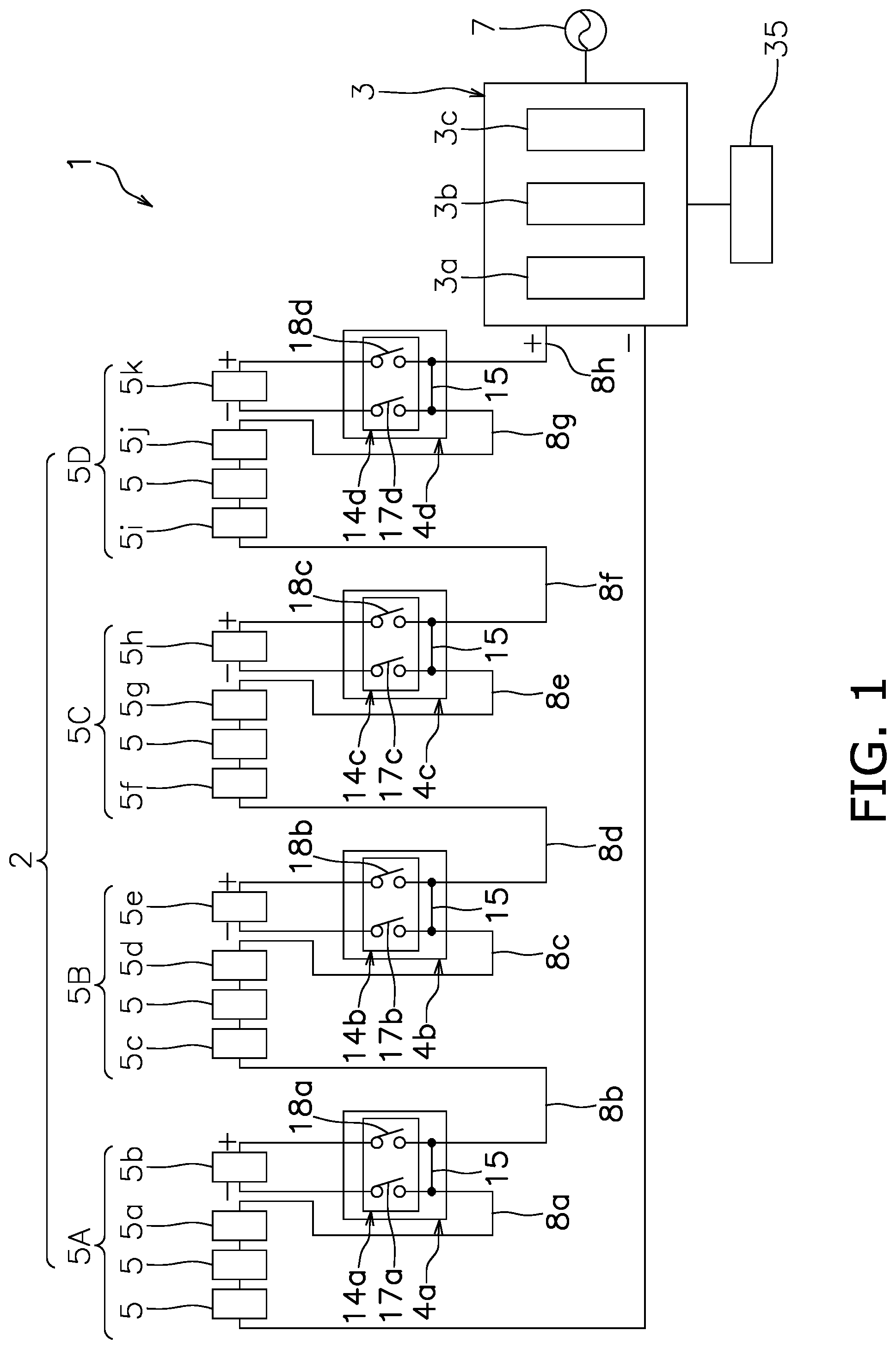
is a block diagram schematically showing a configuration of a solar power generation system 1 according to an aspect of the present invention. The solar power generation system 1 includes a string 2 , an inverter 3 , and a plurality of shut-off devices 4 a to 4 d.
The string 2 includes a plurality of solar cell modules 5 connected in series with each other. The string 2 in the present embodiment is composed of 16 solar cell modules 5 including the solar cell modules 5 a to 5 k . The string 2 includes a plurality of solar cell module groups each including the plurality of solar cell modules 5 .
Specifically, the string 2 includes a plurality of solar cell module groups in which the plurality of solar cell modules 5 are divided into three or more groups. The string 2 in the present embodiment includes solar cell module groups 5 A to 5 D in which the plurality of solar cell modules 5 are divided into four groups.
In order to make the following explanation easier to understand, the solar cell module groups 5 A to 5 D will be described as groups 5 A to 5 D. The group 5 A is an example of a first group, the group 5 B is an example of a second group, and the group 5 C is an example of a third group. The solar cell module 5 b is an example of a first solar cell module. The solar cell module 5 a is an example of a second solar cell module. The solar cell module 5 c is an example of a third solar cell module. The solar cell module 5 e is an example of the fourth solar cell module.
The group 5 A is connected to the inverter 3 and the group 5 B. The group 5 A includes at least the solar cell module 5 a and the solar cell module 5 b among the plurality of solar cell modules 5 . The solar cell module 5 a is connected to the solar cell module 5 b . The solar cell module 5 b is connected to the solar cell module 5 a and the group 5 B. As shown in , the group 5 A in the present embodiment is composed of four solar cell modules 5 including the solar cell modules 5 a and 5 b.
The group 5 B is positioned between the group 5 A and the group 5 C and is connected to the group 5 A and the group 5 C. The group 5 B includes at least the solar cell module 5 c , the solar cell module 5 d , and the solar cell module 5 e among the plurality of solar cell modules 5 . The solar cell module 5 c is connected to the solar cell module 5 b of the group 5 A. The solar cell module 5 d is connected to the solar cell module 5 e . The solar cell module 5 e is connected to the solar cell module 5 d and the group 5 C. The group 5 B in the present embodiment is composed of four solar cell modules 5 including the solar cell modules 5 c , 5 d , 5 e , and one solar cell module 5 disposed between the solar cell module 5 c and the solar cell module 5 d.
The group 5 C is positioned between the group 5 B and the group 5 D and is connected to the group 5 B and the group 5 D. The group 5 C includes at least the solar cell module 5 f , the solar cell module 5 g , and the solar cell module 5 h among the plurality of solar cell modules 5 . The solar cell module 5 f is connected to the solar cell module 5 e of the group 5 B. The solar cell module 5 g is connected to the solar cell module 5 h . The solar cell module 5 h is connected to the solar cell module 5 g and the group 5 C. The group 5 C in the present embodiment is composed of four solar cell module 5 including the solar cell module 5 f , 5 g , 5 h , and one solar cell module 5 disposed between the solar cell module 5 f and the solar cell module 5 g.
The group 5 D is connected to the group 5 C. The group 5 D includes at least the solar cell module 5 i , the solar cell module 5 j , and the solar cell module 5 k among the plurality of solar cell modules 5 . The solar cell module 5 i is connected to the solar cell module 5 h of the group 5 C. The solar cell module 5 j is connected to the solar cell module 5 k . The solar cell module 5 k is connected to the solar cell module 5 j and the inverter 3 . The group 5 D in the present embodiment is composed of four solar cell module 5 including the solar cell modules 5 i , 5 j , 5 k , and one solar cell module 5 disposed between the solar cell module 5 i and the solar cell module 5 j.
Each of the solar cell module groups 5 A to 5 D in the present embodiment includes four solar cell modules 5 connected in series. The solar power generation system 1 may include a solar cell array in which a plurality of the strings 2 are connected in parallel.
Each of the solar cell module 5 receives sunlight to generate electrical power, and outputs the generated electrical power to the inverter 3 . The open circuit voltage of the solar cell module 5 is, for example, 50V. The inverter 3 is connected to the string 2 via a power line 6 . The inverter 3 converts the DC power output from the solar cell modules 5 a into AC power. The inverter 3 is connected to a power system 7 and thereby supplies AC power to a commercial power system and a load device.
Specifically, the inverter 3 includes a DC/DC converter 3 a , a DC/AC inverter 3 b , and a control unit 3 c . The DC/DC converter 3 a converts the voltage of the electrical power output from the solar cell modules 5 into a predetermined voltage that is input to the DC/AC inverter 3 b . The DC/AC inverter 3 b converts the DC power output from the solar cell modules 5 into AC power via the DC/DC converter 3 a . The control unit 3 c includes a CPU, a memory, and the like, and controls the DC/DC converter 3 a and the DC/AC inverter 3 b . Further, the control unit 3 c outputs a control signal to the shut-off devices 4 a to 4 d by power line communication.
The shut-off devices 4 a to 4 d are connected to an electrical path connecting the solar cell modules 5 to each other. The shut-off devices 4 a to 4 d shut off the voltage output from the solar cell module 5 in response to the control signal from the inverter 3 .
The shut-off devices 4 a to 4 d are not provided with a bypass diode. Therefore, when the voltage output from the solar cell modules 5 is shut off by the shut-off devices 4 a to 4 d , the voltage input to the inverter 3 is shut off.
The shut-off device 4 a is connected to an electrical path 8 a and an electrical path 8 b . The electrical path 8 a connects the solar cell modules 5 belonging to the group 5 A to each other. The electrical path 8 a connects the solar cell module 5 a and the solar cell module 5 b . The electrical path 8 b connects the group 5 A and the group 5 B. The electrical path 8 b connects the solar cell module 5 b and the solar cell module 5 c . The shut-off device 4 a shuts off the electrical paths 8 a and 8 b by shutting off the voltage output from the solar cell module 5 b in response to the control signal from the inverter 3 . As a result, the connection between the solar cell module 5 a and the solar cell module 5 b and the connection between the solar cell module 5 b and the solar cell module 5 c (connection between the group 5 A and the group 5 B) are shut off. The shut-off device 4 a is driven by the electrical power generated by the solar cell module 5 b . The shut-off device 4 a is externally attached to the solar cell module 5 b.
The shut-off device 4 b is connected to an electrical path 8 c and an electrical path 8 d . The electrical path 8 c connects the solar cell modules 5 belonging to the group 5 B to each other. The electrical path 8 c connects the solar cell module 5 d and the solar cell module 5 e . The electrical path 8 d connects the group 5 B and the group 5 C. The electrical path 8 d connects the solar cell module 5 e and the solar cell module 5 f . The shut-off device 4 b shuts off the electrical paths 8 c and 8 d by shutting off the voltage output from the solar cell module 5 e in response to the control signal from the inverter 3 . As a result, the connection between the solar cell module 5 d and the solar cell module 5 e and the connection between the solar cell module 5 e and the solar cell module 5 f (connection between the group 5 B and the group 5 C) are shut off. The shut-off device 4 b is driven by the electrical power generated by the solar cell module 5 e . The shut-off device 4 b is externally attached to the solar cell module 5 e.
The shut-off device 4 c is connected to an electrical path 8 e and an electrical path 8 f . The electrical path 8 e connects the solar cell modules 5 belonging to the group 5 C to each other. The electrical path 8 e connects the solar cell module 5 g and the solar cell module 5 h . The electrical path 8 f connects the group 5 C and the group 5 D. The electrical path 8 f connects the solar cell module 5 h and the solar cell module 5 i . The shut-off device 4 c shuts off the electrical paths 8 e and 8 f by shutting off the voltage output from the solar cell module 5 h in response to the control signal from the inverter 3 . As a result, the connection between the solar cell module 5 g and the solar cell module 5 h and the connection between the solar cell module 5 h and the solar cell module 5 i (connection between the group 5 C and the group 5 D) are shut off. The shut-off device 4 c is driven by the electrical power generated by the solar cell module 5 h . The shut-off device 4 c is externally attached to the solar cell module 5 h.
The shut-off device 4 d is connected to an electrical path 8 g and electrical path 8 h . The electrical path 8 g connects the solar cell modules 5 belonging to the group 5 D to each other. The electrical path 8 g connects the solar cell module 5 j and the solar cell module 5 k . The electrical path 8 h connects the group 5 D and the inverter 3 . The electrical path 8 h connects the solar cell module 5 k and the inverter 3 . The shut-off device 4 d shuts off the electrical paths 8 g and 8 h by shutting off the voltage output from the solar cell module 5 k in response to the control signal from the inverter 3 . As a result, the connection between the solar cell module 5 j and the solar cell module 5 k and the connection between the solar cell module 5 k and the inverter 3 are shut off. The shut-off device 4 d is driven by the electrical power generated by the solar cell module 5 k . The shut-off device 4 d is externally attached to the solar cell module 5 k.
is a block diagram schematically showing a configuration of the shut-off device 4 a . The shut-off device 4 a includes a regulator 11 , a signal receiving unit 12 , a relay control unit 13 , a relay 14 a , and a bypass circuit 15 .
The regulator 11 uses the electrical power generated by the solar cell module 5 b as a power source to generate a drive power source for driving the shut-off device 4 a and supplies the drive power source in a stable state to the shut-off device 4 a . Here, the regulator 11 uses only the electrical power generated by a single solar cell module 5 (solar cell module 5 b ) to generate the drive power source for the shut-off device 4 a . Since the drive voltage range of the regulator 11 can be kept small, the manufacturing cost of the shut-off device 4 a can be reduced.
is a circuit diagram schematically showing a configuration of the regulator 11 . The configuration of the regulator 11 is a well-known configuration, and includes input terminals 21 a , 21 b , output terminals 22 a , 22 b , a line filter 23 , capacitors 24 , 25 , a booster circuit 26 , a switching element 27 , a control circuit 28 , a transformer 29 , a diode 30 , a DC/DC converter 31 , a feedback circuit 32 and the like.
The signal receiving unit 12 receives a control signal from the control unit 3 c of the inverter 3 and outputs the received control signal to the relay control unit 13 . Specifically, the signal receiving unit 12 receives the control signal from the control unit 3 c of the inverter 3 via a signal detecting unit 16 that detects the control signal from the control unit 3 c of the inverter 3 .
On the basis of the signal output from the signal receiving unit 12 , the relay control unit 13 controls the current value flowing through the coil of the relay 14 a to control the opening and closing of the contacts of the relay 14 a . The relay 14 a is, for example, a mechanical relay, and can open and close a high-voltage direct current.
The relay 14 a includes a first opening/closing unit 17 a and a second opening/closing unit 18 a . The first opening/closing unit 17 a is disposed in the electrical path 8 a . The first opening/closing unit 17 a opens/closes the connection between the solar cell module 5 a and the solar cell module 5 b . The first opening/closing unit 17 a is connected to a terminal on a cathode side of the solar cell module 5 b . The second opening/closing unit 18 a is disposed in the electrical path 8 b . The second opening/closing unit 18 a opens/closes the connection between the solar cell module 5 b and the solar cell module 5 c . The second opening/closing unit 18 a is connected to a terminal on an anode side of the solar cell module 5 b.
When the drive power source is not supplied to the shut-off device 4 a , the first opening/closing unit 17 a and the second opening/closing unit 18 a are always in an open state. Therefore, when the shut-off device 4 a is not driven, the connection between the solar cell module 5 a and the solar cell module 5 b and the connection between the solar cell module 5 b and the solar cell module 5 c are shut off.
The bypass circuit 15 is a circuit for allowing the signal receiving unit 12 to receive the control signal from the control unit 3 c when the shut-off device 4 a is in a shut-off state. When the electrical paths 8 a and 8 b are shut off by the shut-off device 4 a , the signal receiving unit 12 can receive the control signal from the control unit 3 c via the bypass circuit 15 .
The shut-off devices 4 b to 4 d have the same configuration as the shut-off device 4 a except that the connected electrical path is different from the shut-off device 4 a . The shut-off device 4 b includes a relay 14 b including a first opening/closing unit 17 b and a second opening/closing unit 18 b . The first opening/closing unit 17 b is disposed in the electrical path 8 c . The first opening/closing unit 17 b is connected to a terminal on a cathode side of the solar cell module 5 e , and opens/closes the connection between the solar cell module 5 d and the solar cell module 5 e . The second opening/closing unit 18 b is disposed in the electrical path 8 d . The second opening/closing unit 18 b is connected to a terminal on an anode side of the solar cell module 5 b , and opens/closes the connection between the solar cell module 5 e and the solar cell module 5 f.
The shut-off device 4 c includes a relay 14 c including a first opening/closing unit 17 c and a second opening/closing unit 18 c . The first opening/closing unit 17 c is disposed in the electrical path 8 e . The first opening/closing unit 17 c is connected to a terminal on a cathode side of the solar cell module 5 h , and opens/closes the connection between the solar cell module 5 g and the solar cell module 5 h . The second opening/closing unit 18 c is disposed in the electrical path 8 f . The second opening/closing unit 18 c is connected to a terminal on an anode side of the solar cell module 5 h , and opens/closes the connection between the solar cell module 5 h and the solar cell module 5 i.
The shut-off device 4 d includes a relay 14 d including a first opening/closing unit 17 d and a second opening/closing unit 18 d . The first opening/closing unit 17 d is disposed in the electrical path 8 g . The first opening/closing unit 17 d is connected to a terminal on a cathode side of the solar cell module 5 k , and opens/closes the connection between the solar cell module 5 j and the solar cell module 5 k . The second opening/closing unit 18 d is disposed in the electrical path 8 h . The second opening/closing unit 18 d is connected to a terminal on an anode side of the solar cell module 5 k , and opens/closes the connection between the solar cell module 5 k and the inverter 3 . In this embodiment, the second opening/closing unit 18 d of the shut-off device 4 d may be omitted.
Next, an example of the operation modes of the shut-off devices 4 a to 4 d will be described with reference to . The operation modes of the shut-off devices 4 a to 4 d include three operation modes of a start mode, an active mode, and a safety mode. The safety mode includes a normal shut-off mode and an emergency safety shut-off mode. Therefore, the shut-off devices 4 a to 4 d operate in four operation modes: a start mode, an active mode, a normal shut-off mode, and an emergency safety shut-off mode.
The start mode is a mode when sunlight starts to hit the solar cell module 5 . At this time, each of the solar cell modules 5 receives sunlight to generate electrical power. Then, the shut-off device 4 a is driven by the drive power source generated by the regulator 11 from the electrical power generated by the solar cell module 5 b . When the shut-off device 4 a is driven and the relay control unit 13 receives the control signal from the control unit 3 c of the inverter 3 via the signal receiving unit 12 , the relay control unit 13 performs control so as to close the first opening/closing unit 17 a and the second opening/closing unit 18 a of the first relay 14 a as shown in .
Similarly, the shut-off device 4 b is driven by the electrical power generated by the solar cell module 5 e , and closes the first opening/closing unit 17 b and the second opening/closing unit 18 b of the relay 14 b in response to the control signal from the control unit 3 c of the inverter 3 . Similarly, the shut-off device 4 c is driven by the electrical power generated by the solar cell module 5 h , and closes the first opening/closing unit 17 c and the second opening/closing unit 18 c of the relay 14 c in response to the control signal from the control unit 3 c of the inverter 3 . Similarly, the shut-off device 4 d is driven by the electrical power generated by the solar cell module 5 k , and closes the first opening/closing unit 17 d and the second opening/closing unit 18 d of the relay 14 d in response to the control signal from the control unit 3 c of the inverter 3 . As a result, the groups 5 A to 5 D are connected via the shut-off devices 4 a to 4 d , and the electrical power generated by each solar cell module 5 including the solar cell modules 5 a to 5 k is output to the inverter 3 .
The active mode is a state in which each of the solar cell modules 5 receives sunlight during the day to generate electricity, which is substantially the same as the start mode. Therefore, in the active mode, the groups 5 A to 5 D are in a connected state via the shut-off devices 4 a to 4 d , and the electrical power generated by each of the solar cell modules 5 is output to the inverter 3 .
The normal shut-off mode is a mode when the solar cell modules 5 are not receiving sunlight during nighttime or due to the influence of the weather such as rain. Therefore, in the normal shut-off mode, electrical power is not generated by the solar cell modules 5 , and drive power source is not supplied from the solar cell module 5 b to the shut-off device 4 a . Similarly, drive power source is not supplied to the shut-off device 4 b , the shut-off device 4 c , and the shut-off device 4 d . Therefore, in the normal shut-off mode, the contacts of the first opening/closing units 17 a to 17 d and the second opening/closing units 18 a to 18 d of the shut-off devices 4 a to 4 d are in the open state. In the present embodiment, electrical power is supplied to the inverter 3 from the AC power supply, and the control signal is always output from the control unit 3 c of the inverter 3 except in the emergency safety shut-off mode.
In the normal shut-off mode, for example, when the power generation of the solar cell modules 5 b , 5 e , 5 h , 5 k is unstable due to unstable weather or the like, the relays 14 a to 14 d operate on/off according to the electrical power supplied by the solar cell modules 5 b , 5 e , 5 h , 5 k.
The emergency safety shut-off mode is a mode in which the electrical paths 8 a to 8 h are shut off during the start mode or the active mode to stop the output of electrical power from the solar cell module 5 to the inverter 3 . In the present embodiment, as shown in , an operation switch 35 is connected to the inverter 3 , and when the operation switch 35 is operated while the shut-off devices 4 a to 4 d are in the start mode or the active mode, the shut-off devices 4 a to 4 d switch the operation mode to the emergency safety shut-off mode.
Specifically, when the operation switch 35 is operated, the control unit 3 c stops the output of the control signal. When the signal detecting unit 16 detects that the control signal has been stopped for a certain period, all the contacts of the first opening/closing units 17 a to 17 d and the second opening/closing of the relays 14 a to 14 d are opened via the signal receiving unit 12 and the relay control unit 13 . As a result, the voltage output from all the solar cell modules 5 is shut off.
In the solar power generation system 1 having the above configuration, when the operation mode of the shut-off devices 4 a to 4 d is the emergency safety shut-off mode, the shut-off devices 4 a to 4 d can shut off the plurality of solar cell modules 5 . For example, the shut-off device 4 a can shut off the connection between the group 5 A and the group 5 B, and further, the connection between the solar cell module 5 a belonging to the group 5 A and the solar cell module 5 b . As a result, the installation cost of the shut-off device can be reduced as compared with the case where the shut-off device is installed for each of the solar cell modules 5 . Further, it is possible to provide a solar power generation system having higher safety than the case where the solar cell modules 5 and the inverter 3 are shut off in the string 2 unit.
Here, in the emergency safety shut-off mode, the open circuit voltage of the string 2 is preferably divided into 165 V or less. When the open circuit voltage of the solar cell module 5 is 50 V, the open circuit voltage of the string 2 is 800 V because the string 2 is composed of 16 solar cell modules 5 . The open circuit voltage for each group 5 A to 5 D is 200V. By configuring the shut-off devices 4 a to 4 d as described above, in the emergency safety shut-off mode, the open circuit voltage for each group 5 A to 5 D is divided into 150V and 50V, and the connections between the groups 5 A to 5 D are also shut off. That is, in a state where the contacts of the first opening/closing units 17 a to 17 d and the second opening/closing units 18 a to 18 d of the shut-off devices 4 a to 4 d are all open, the plurality of solar cell modules 5 composing the string 2 are divided into three solar cells modules 5 and one solar cell module 5 . Accordingly, if the solar cell modules 5 continue to generate power in the emergency safety shut-off mode, the open circuit voltage becomes 150 V at the maximum, and the safer is higher than when the connection with the inverter 3 is shut off in the string 2 unit.
Further, in the solar power generation system 1 , it is possible to secure communication between the drive power supply of the shut-off devices 4 a to 4 d and the inverter 3 by using the power line 6 . As a result, for example, when the shut-off devices 4 a to 4 d are installed in an existing solar power generation system, additional wiring for connecting the inverter 3 and the shut-off devices 4 a to 4 d is not required. Therefore, it is possible to reduce the installation cost when installing the shut-off devices 4 a to 4 d in an existing solar power generation system.
Further, since the shut-off devices 4 a to 4 d may be connected to one solar cell module 5 , the wiring is shorter and simpler than the case where the shut-off devices 4 a to 4 d are connected across a plurality of solar cell modules 5 . As a result, for example, it is possible to reduce the installation cost when installing the shut-off devices 4 a to 4 d in an existing solar power generation system, and to perform the construction with high flexibility.
Further, since the bypass diode is omitted in the shut-off devices 4 a to 4 d , the manufacturing cost of the shut-off devices 4 a to 4 d can be reduced.
Further, the bypass circuit 15 in the shut-off devices 4 a to 4 d enables the operation mode of the shut-off devices 4 a to 4 d to be switched from the emergency safety shut-off mode to the start mode according to the control signal of the control unit 3 c.
Although one embodiment of the present invention has been described above, the present invention is not limited to the above embodiment, with various modifications being possible without departing from the gist of the invention.
In the above embodiment, each of the groups 5 A to 5 D includes four solar cell modules 5 , but the number of the solar cell modules 5 is not limited to the above embodiment. Further, each of the groups 5 A to 5 D does not necessarily include the same number of solar cell modules 5 . For example, group 5 A may include three solar cell modules 5 and group 5 B may include five solar cell modules 5 .
In the embodiment, the string 2 includes four groups 5 A- 5 D, but the number of groups is not limited to the embodiment. For example, string 2 may include three groups or four or more groups. Further, the arrangement and the number of the shut-off devices 4 a to 4 d are not limited to the above-described embodiment. For example, in the above embodiment, the shut-off device 4 d and the solar cell module 5 f may be omitted.
In the above embodiment, the first opening/closing unit 17 a opens/closes the connection between the solar cell module 5 a and the solar cell module 5 b , but as shown , for example, the first opening/closing unit 17 a may open/close the connection the solar cell module 5 a and the solar cell module 5 connected to a terminal on a cathode side of the solar cell module 5 a . In this case, in group A, the open circuit voltage is divided into 100V. The shut-off devices 4 b to 4 c may also be disposed so that the open circuit voltage is divided into 100V in the groups 5 B to 5 D.
In the above-described embodiment, switching to the emergency safety shut-off mode is performed by operating the operation switch 35 , but switching from the start mode or the active mode to the emergency safety shut-off mode is not limited to the above-described embodiment. For example, the solar power generation system 1 may be provided with a sensor that detects the output state of the solar cell modules 5 a . The control unit 3 c of the inverter 3 may stop the output of the control signal when an abnormality is detected from the output state of the solar cell modules 5 detected by the sensor, and shut-off devices 4 a to 4 d may switch the operation mode to the emergency safety shut-off mode. Alternatively, when a fire alarm communicator or a fire alarm is connected to the inverter 3 , the inverter 3 may stop the output of the control signal when the inverter receives a signal from the fire alarm communicator or fire alarm, and the shut-off devices 4 a to 4 d may switch the operation mode to the emergency safety shut-off mode.
In the above embodiment, the relay 14 a of the shut-off device 4 a includes two contacts of the first opening/closing unit 17 a and the second opening/closing unit 18 a , but the relay 14 a may comprise of two relays each including a single contact.
REFERENCE NUMERALS
•
• 1 Solar power generation system • 2 String • 3 Inverter • 4 a - 4 d Shut-off device • 5 A- 5 D Solar cell module group • 5 Solar cell module • 8 a - 8 h Electrical path • 12 Signal receiving unit • 15 Bypass circuit • 17 a - 17 d first opening/closing unit • 18 a - 18 d second opening/closing unit
Figures (6)
Citations
This patent cites (8)
- US20160372929
- US20180248359
- US20180316308
- US20220109399
- US2012-511299
- US3189106
- US2016135016
- US2020/174657