Motor Including a Busbar Having a Plurality of Terminals
Abstract
The present invention may provide a motor including a stator including coils, a rotor disposed inside the stator, and a busbar disposed above the stator, wherein the stator includes a first unit stator core and a second unit stator core, the coils include a first unit coil and a second unit coil, the busbar includes a body and a plurality of terminals connected to the coils of the stator, the plurality of terminals include first terminals and second terminals, the first unit coil is wound around the first unit stator core, the second unit coil is wound around the second unit stator core, one end of the first unit coil and one end of the second unit coil are connected to the first terminals, and the other end of the first unit coil and the other end of the second unit coil are connected to the second terminals.
Claims (17)
1. A motor comprising: a stator including coils; a rotor disposed inside the stator; and a busbar disposed above the stator, wherein the stator includes a first unit stator core and a second unit stator core, the coils include a first unit coil and a second unit coil, and the busbar includes a body and a plurality of terminals connected to the coils of the stator, wherein the plurality of terminals include first terminals and second terminals, the first unit coil is wound around the first unit stator core, the second unit coil is wound around the second unit stator core, one end of the first unit coil and one end of the second unit coil are connected to the first terminals, and an other end of the first unit coil and an other end of the second unit coil are connected to the second terminals, wherein the second terminals include a neutral terminal and a plurality of phase terminals, wherein the first terminals and the second terminals share overlapping regions in a shaft direction, wherein the first terminals are spaced apart from the second terminals in the shaft direction, wherein each first terminal includes a first body unit and a first support, wherein the first support extends from any portion of the first body unit, wherein the neutral terminal and the phase terminals each includes a second body unit and a second support, wherein the second body unit of the neutral terminal overlaps the first supports in the shaft direction, and wherein the second body units of the phase terminals overlap the first body units in the shaft direction.
7. A motor comprising: a stator including coils; a rotor disposed inside the stator; and a busbar disposed above the stator, wherein the stator includes a first unit stator core and a second unit stator core, the coils include a first unit coil and a second unit coil, and the busbar includes a body and a plurality of terminals connected to the coils of the stator, wherein the plurality of terminals include first terminals and second terminals, the first unit coil is wound around the first unit stator core, the second unit coil is wound around the second unit stator core, one end of the first unit coil and one end of the second unit coil are connected to the first terminals, an other end of the first unit coil and an other end of the second unit coil are connected to the second terminals, the other end of the first unit coil is connected to a neutral terminal; and the other end of the second unit coil is connected to one of a plurality of phase terminals, and wherein the first terminals and the second terminals share overlapping regions in a shaft direction, wherein the first terminals are spaced apart from the second terminals in the shaft direction, wherein each first terminal includes a first body unit and a first support, wherein the first support extends from any portion of the first body unit, wherein the neutral terminal and the phase terminals each includes a second body unit and a second support, wherein the second body unit of the neutral terminal overlaps the first supports in the shaft direction, and wherein the second body units of the phase terminals overlap the first body units in the shaft direction.
8. A motor comprising: a stator including coils; a rotor disposed inside the stator; and a busbar disposed above the stator, wherein the stator includes a first unit stator core and a second unit stator core, the coils include a first unit coil and a second unit coil, and the busbar includes a body and a plurality of terminals connected to the coils of the stator, wherein the plurality of terminals include first terminals and second terminals, the first unit coil is wound around the first unit stator core, the second unit coil is wound around the second unit stator core, one end of the first unit coil and one end of the second unit coil are connected to the first terminals, an other end of the first unit coil and an other end of the second unit coil are connected to the second terminals, wherein the second terminals include two groups each including a neutral terminal and a plurality of phase terminals, and wherein the two groups are electrically divided, and wherein the first terminals and the second terminals share overlapping regions in a shaft direction, wherein the first terminals are spaced apart from the second terminals in the shaft direction, wherein each first terminal includes a first body unit and a first support, wherein the first support extends from any portion of the first body unit, wherein the neutral terminal and the phase terminals each includes a second body unit and a second support, wherein the second body unit of the neutral terminal overlaps the first supports in the shaft direction, and wherein the second body units of the phase terminals overlap the first body units in the shaft direction.
9. A motor comprising; a stator including coils; a rotor disposed inside the stator; and a busbar disposed above the stator, wherein the busbar includes a body and a plurality of terminals connected to the coils, and the coils include a first unit coil and a second unit coil, wherein the plurality of terminals include first terminals and second terminals, wherein the first terminals and the second terminals share overlapping regions in a shaft direction, and wherein the first terminals are spaced apart from the second terminals in the shaft direction, a thickness of the first terminal is smaller than a thickness of the second terminal in the overlapping regions, one end of the first unit coil and one end of the second unit coil are connected to the first terminals, and an other end of the first unit coil and an other end of the second unit coil are connected to the second terminals, the first terminals include first connecting terminals and second connecting terminals, wherein each of the first connecting terminals and the second connecting terminals includes bent portions having curvatures, first body units extending from both ends of each of the bent portions, and first supports extending from one portion of the first body units, respectively, in a radial direction; and wherein the bent portions of the first connecting terminals each has a shape extending inward from the first body units of the first connecting terminals, wherein the bent portions of the second connecting terminals each has a shape extending outward from the first body units of the second connecting terminals, wherein the second terminals include a neutral terminal and a plurality of phase terminals, wherein the bent portions of the first connecting terminals overlap the neutral terminal in the shaft direction, and wherein the bent portions of the second connecting terminals overlap the first supports of the first connecting terminals, the neutral terminal, and the phase terminals in the shaft direction.
Show 13 dependent claims
2. The motor of claim 1 , wherein the coils comprise two units of coils disposed between the first unit coil and the second unit coil.
3. The motor of claim 2 , wherein: the first body units have curvatures, and the first supports extend from one portion of the first bodies, respectively, in a radial direction.
4. The motor of claim 1 , wherein the other end of the first unit coil is connected to the neutral terminal, and the other end of the second unit coil is connected to one of the plurality of phase terminals.
5. The motor of claim 4 , wherein: the first body units have curvatures, and the first supports extend from one portion of the first body units, respectively, in a radial direction.
6. The motor of claim 1 , wherein: the first body units have curvatures, and the first supports extend from one portion of the first body units, respectively, in a radial direction.
10. The motor of claim 9 , wherein: a width of the bent portions in the radial direction is greater than a thickness of the bent portions; and a width in the radial direction is smaller than a thickness in a vertical direction in each of the first body units and the first supports.
11. The motor of claim 10 , wherein the bent portions are disposed to be lower than the first body units and the first supports.
12. The motor of claim 9 , wherein: adjacent body units of the first body units of the plurality of connecting terminals do not overlap in the shaft direction.
13. The motor of claim 12 , wherein the bent portions of one of the plurality of connecting terminals overlap the first body units or the first supports of another connecting terminal of the plurality of connecting terminals in the shaft direction.
14. The motor of claim 9 , wherein: the second terminals include second body units having curvatures and second supports extending from one portion of the second body units, respectively, in the radial direction; and the second supports overlap the bent portions of the first terminal in the shaft direction.
15. The motor of claim 14 , wherein: the second supports of at least one of the plurality of phase terminals overlap the first body units of the first terminal in the shaft direction.
16. The motor of claim 9 , wherein: a width of the bent portions in the radial direction is greater than a thickness of the bent portions; and a width in the radial direction is smaller than a thickness in a vertical direction in each of the first body units and the first supports.
17. The motor of claim 16 , wherein the bent portions are disposed to be lower than the first body units and the first supports.
Full Description
Show full text →
CROSS-REFERENCE TO RELATED APPLICATIONS
This application is the U.S. national stage application of International Patent Application No. PCT/KR2019/011807, filed Sep. 11, 2019, which claims the benefit under 35 U.S.C. § 119 of Korean Application No. 10-2018-0108451, filed Sep. 11, 2018, the disclosures of each of which are incorporated herein by reference in their entirety.
TECHNICAL FIELD
The present invention relates to a motor.
BACKGROUND ART
Electronic power steering (EPS) systems secure turning stability and provide rapid restoring forces so that drivers can travel safely. Such an EPS system controls driving of a steering shaft of a vehicle by driving a motor using an electronic control unit (ECU) according to operation conditions detected by a vehicle speed sensor, a torque angle sensor, a torque sensor, and the like.
A motor includes a rotor and a stator. The stator may include stator cores and a coil. The coil is wound around the stator cores. In the case of series winding, winding work may be performed by winding one coil around the plurality of stator cores disposed to be spaced apart from each other at once. In this case, a connecting portion of the coil should pass over another stator core. In this case, an insulation problem of the coil may occur. In order to insulate the coil, the connecting portion may be inserted into an insulation tube, but there are problems in that assembly is difficult, and thus manufacturing automation is difficult.
Technical Problem
Electronic power steering (EPS) systems secure turning stability and provide rapid restoring forces so that drivers can travel safely. Such an EPS system controls driving of a steering shaft of a vehicle by driving a motor using an electronic control unit (ECU) according to operation conditions detected by a vehicle speed sensor, a torque angle sensor, a torque sensor, and the like.
A motor includes a rotor and a stator. The stator may include stator cores and a coil. The coil is wound around the stator cores. In the case of series winding, winding work may be performed by winding one coil around the plurality of stator cores disposed to be spaced apart from each other at once. In this case, a connecting portion of the coil should pass over another stator core. In this case, an insulation problem of the coil may occur. In order to insulate the coil, the connecting portion may be inserted into an insulation tube, but there are problems in that assembly is difficult, and thus manufacturing automation is difficult.
Technical Solution
One aspect of the present invention provides a motor including a stator including coils, a rotor disposed inside the stator, and a busbar disposed above the stator, wherein the stator includes a first unit stator core and a second unit stator core, the coils include a first unit coil and a second unit coil, the busbar includes a body and a plurality of terminals connected to the coils of the stator, the plurality of terminals include first terminals and second terminals, the first unit coil is wound around the first unit stator core, the second unit coil is wound around the second unit stator core, one end of the first unit coil and one end of the second unit coil are connected to the first terminals, and the other end of the first unit coil and the other end of the second unit coil are connected to the second terminals.
Two unit coils may be disposed between the first unit coil and the second unit coil.
The second terminals may include a neutral terminal and a plurality of phase terminals.
The other end of the first unit coil may be connected to the neutral terminal, and the other end of the second unit coil may be connected to one of the plurality of phase terminals.
The second terminals may include two groups each including the neutral terminal and the plurality of phase terminals, and the two groups may be electrically divided.
Another aspect of the present invention provides a motor including a stator including coils, a rotor disposed inside the stator, and a busbar disposed above the stator, wherein the busbar includes a body and a plurality of terminals connected to the coils, the coils include a first unit coil and a second unit coil, the plurality of terminals include first terminals and second terminals, the first terminals and the second terminals include overlap regions in a shaft direction, a thickness of the first terminal is smaller than a thickness of the second terminal in the overlap region, one end of the first unit coil and one end of the second unit coil are connected to the first terminals, and the other end of the first unit coil and the other end of the second unit coil are connected to the second terminals.
Still another aspect of the present invention provides a motor including a stator including coils, a rotor disposed inside the stator, and a busbar disposed above the stator, wherein the busbar includes a body and a plurality of terminals connected to the coils, the coils include a first unit coil and a second unit coil, the plurality of terminals include first connecting terminals and second connecting terminals, the first connecting terminals include bent regions which overlap the second connecting terminals in a shaft direction, and one end of the first unit coil and one end of the second unit coil are connected to the first connecting terminals.
The first terminals may include first bodies having curvatures and first supports extending from one portions of the first bodies in a radial direction, and at least any one of the first body and the first supports may overlap the second terminal in a shaft direction.
In each of the first body and the first support, a width may be greater than a thickness. The second terminals may include second bodies having curvatures and second supports extending from one portions of the second bodies in the radial direction, and the second bodies may overlap the first terminals in the shaft direction.
The first terminals may include a plurality of connecting terminals, the second terminals may include a neutral terminal and a plurality of phase terminals, and the second body of the neutral terminal may overlap the first support of the first terminal in the shaft direction.
The second support of each of the plurality of phase terminals may be disposed between the first supports of one connecting terminal of the plurality of connecting terminal in the circumferential direction.
The second body of the plurality of phase terminals may overlap the first body of the first terminal in the shaft direction.
The first terminals may include bent portions having curvatures, third bodies extending from both ends of each of the bent portions, and third supports extending from one portions of the third bodies in a radial direction, and at least any one of the third body, the bent portion, and the third support may overlap the second terminal in a shaft direction.
A width of the bent portion may be greater than a thickness thereof.
In each of the third body and the third support, a width in the radial direction may be smaller than a thickness in a vertical direction.
The bent portion may be disposed to be lower than the third body and the third support.
The first terminals may include a plurality of connecting terminals, and third bodies of the plurality of connecting terminals may not overlap in the shaft direction.
The bent portion of one of the plurality of connecting terminals overlaps the third body or the third support of another of the plurality of connecting terminals in the shaft direction.
The second terminals may include fourth bodies having curvatures and fourth supports extending from one portions of the fourth bodies in the radial direction, and the fourth support may overlap the first terminal in the shaft direction.
The second terminals may include a neutral terminal and a plurality of phase terminals, and the fourth support of at least one of the plurality of phase terminals may overlap the first body of the first terminal in the shaft direction.
Advantageous Effects
According to embodiments, an advantageous effect is provided in that assembly is facilitated and thus manufacturing automation is possible in series winding.
According to embodiments, an advantageous effect is provided in that insulation of a coil is easily implemented even in the series winding.
DESCRIPTION OF DRAWINGS
is a side cross-sectional view illustrating a motor according to an embodiment.
is a view illustrating a busbar of a motor according to a first embodiment.
is a view illustrating a terminal.
is a view illustrating a first terminal illustrated in .
is a cross-sectional view illustrating the first terminal illustrated in .
is a view illustrating a plurality of first terminals.
is a view illustrating the plurality of first terminals which overlap in a shaft direction.
is a view illustrating a second terminal.
is a view illustrating an overlap region of the first terminal and the second terminal.
is a view illustrating a modified example of the second terminal.
is a view illustrating a busbar of a motor according to a second embodiment.
is a view illustrating a terminal illustrated in .
is a view illustrating a first connecting terminal of a first terminal illustrated in .
is a view illustrating a second connecting terminal of the first terminal illustrated in .
is a view illustrating a second terminal.
is a view illustrating an overlap region of the first terminal and the second terminal (neutral terminal).
is a view illustrating an overlap region of the first terminal and the second terminal (phase terminal).
is a view illustrating an overlap region of the first connecting terminal and the second connecting terminal which are the first terminals.
MODES OF THE INVENTION
Hereinafter, exemplary embodiments of the present invention will be described in detail with reference to the accompanying drawings.
However, the technical spirit of the present invention is not limited to some embodiments which will be described and may be realized using various other embodiments, and at least one component of the embodiments may be selectively coupled, substituted, and used to realize the technical spirit within the range of the technical spirit.
In addition, unless clearly and specifically defined otherwise by context, all terms (including technical and scientific terms) used herein can be interpreted as having customary meanings to those skilled in the art, and meanings of generally used terms, such as those defined in commonly used dictionaries, will be interpreted by considering contextual meanings of the related technology.
In addition, the terms used in the embodiments of the present invention are considered in a descriptive sense and not for limiting the present invention.
In the present specification, unless clearly indicated otherwise by the context, singular forms include the plural forms thereof, and in a case in which “at least one (or one or more) among A, B, and C” is described, this may include at least one combination among all possible combinations of A, B, and C.
In addition, in descriptions of components of the present invention, terms such as “first,” “second,” “A,” “B,” “(a),” and “(b)” can be used.
The terms are only to distinguish one element from another element, and an essence, order, and the like of the element are not limited by the terms.
In addition, it should be understood that, when an element is referred to as being “connected or coupled” to another element, such a description may include both of a case in which the element is directly connected or coupled to another element and a case in which the element is connected or coupled to another element with still another element disposed therebetween.
In addition, in a case in which any one element is described as being formed or disposed “on or under” another element, such a description includes both a case in which the two elements are formed or disposed in direct contact with each other and a case in which one or more other elements are interposed between the two elements. In addition, when one element is described as being disposed “on or under” another element, such a description may include a case in which the one element is disposed at an upper side or a lower side with respect to another element.
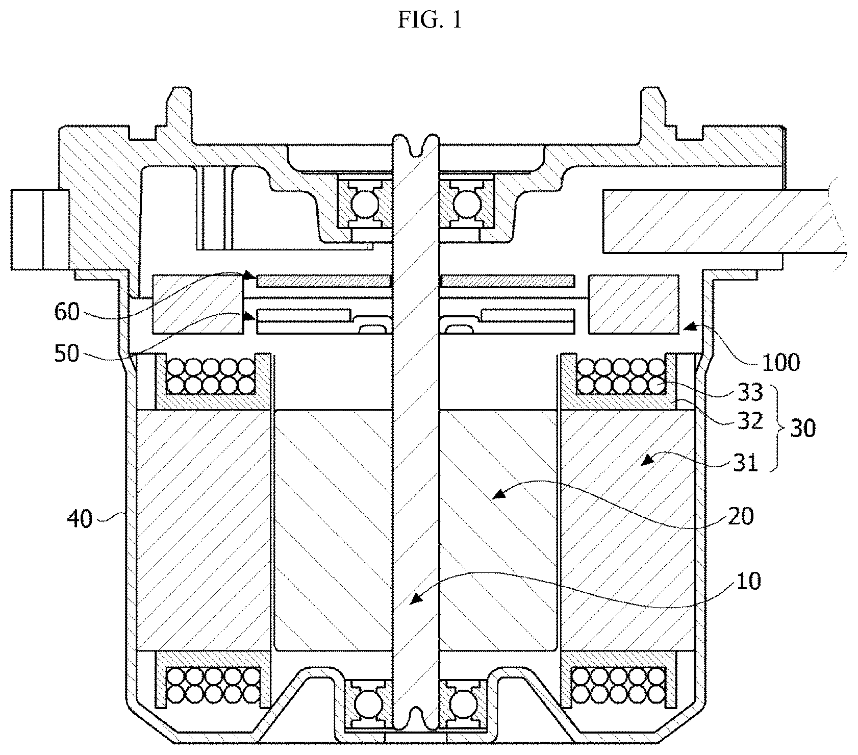
is a side cross-sectional view illustrating a motor according to an embodiment.
Referring to , the motor according to the embodiment may include a rotating shaft 10 , a rotor 20 , a stator 30 , and a busbar 100 .
The rotating shaft 10 may be coupled to the rotor 20 . When a current is supplied so that an electrical interaction occurs between the rotor 20 and the stator 30 , the rotor 20 is rotated and the rotating shaft 10 is rotated in conjunction with the rotation of the rotor 20 . The rotating shaft 10 may be connected to a steering shaft of a vehicle to transmit power to the steering shaft.
The rotor 20 is rotated due to the electrical interaction with the stator 30 .
The rotor 20 may include a rotor core and magnets. The rotor core may be formed in a form in which a plurality of thin circular steel plates are stacked or a single cylindrical form. A hole coupled to the rotating shaft 10 may be disposed at a central portion of the rotor core. The magnets may be disposed on an outer circumferential surface or an inner portion of the rotor core.
The stator 30 may include a stator core 31 , an insulator 32 , and coils 33 . The insulator 32 is installed on the stator core 31 . The coil 33 is wound around the insulator 32 . An electrical interaction occurs between the coil 33 and the rotor 20 .
The rotor 20 and the stator 30 may be accommodated in a housing 40 .
A sensing magnet 50 is coupled to the rotating shaft 10 to operate in conjunction with the rotor 20 . The sensing magnet 50 is a device for detecting a position of the rotor 20 .
A sensor configured to detect a magnetic force of the sensing magnet 50 may be disposed on a circuit board 60 . In this case, the sensor may be a Hall integrated circuit (IC). The sensor detects changes in an N-pole and an S-pole of the sensing magnet 50 to generate a sensing signal.
The busbar 100 is disposed above the stator 30 .
•
• is a view illustrating a busbar of a motor according to a first embodiment.
Referring to , a busbar 100 may include terminals 120 disposed in a body 110 having an annular shape.
The busbar 100 includes the body 110 and the terminals 120 . The body 110 may be a mold product formed through an injection molding process.
The body 110 includes a hole 111 at a central portion thereof. The terminals 120 may be disposed in the body 110 , and some end portions of the terminals 120 may be disposed to be exposed from the body 110 . An entirety of the body 110 may have a annular shape. The terminals 120 may include a phase terminal and a neutral terminal.
is a view illustrating the terminal.
Referring to , the terminals 120 may be divided into a first group 120 - 1 and a second group 120 - 2 . The first group 120 - 1 may be electrically divided from the second group 120 - 2 . Each of the first group 120 - 1 and the second group 120 - 2 may include first terminals 121 and second terminals 122 and 123 . The first terminal 121 is the terminal 120 connecting the coils 33 , and the second terminals 122 and 123 are a neutral terminal 122 and a phase terminal 123 , respectively. The first group 120 - 1 and the second group 120 - 2 may be disposed to be spatially divided by a reference line L passing through a center C of the busbar 100 .
is a view illustrating the first terminal illustrated in .
Referring to , a stator core 31 may include a first unit stator core 31 A and a second unit stator core 31 B. The coils 33 may include a first unit coil 33 A and a second unit coil 33 B. The first unit coil 33 A is wound around the first unit stator core 31 A. The second unit coil 33 B is wound around the second unit stator core 31 B.
The first unit coil 33 A is an independent coil which is not connected to the second unit coil 33 B. The first unit coil 33 A includes a first end A 1 and a second end A 2 . When the first unit coil 33 A is wound, any one of the first end A 1 and the second end A 2 may be a starting end of the first unit coil 33 A, and the remaining one thereof may be a finishing end thereof. The second unit coil 33 B includes a third end B 1 and a fourth end B 2 . Any one of the third end B 1 and the fourth end B 2 may be a starting end of the second unit coil 33 B, and the remaining one thereof may be a finishing end thereof.
The first terminal 121 is a connecting terminal and connects one end of the first unit coil 33 A and one end of the second unit coil 33 B. In this case, the term “one end” denotes an end among the first end A 1 , the second end A 2 , the third end B 1 , and the fourth end B 2 connected to the first terminal 121 . For example, in , one ends may be the first end A 1 and the third end B 1 .
The second terminals 122 and 123 connect the other end of first unit coil 33 A and the other end of the second unit coil 33 B. In this case, the term “the other end” denotes an end among the first end A 1 , the second end A 2 , the third end B 1 , and the fourth end connected to the second terminals 122 and 123 . For example, in , the other ends may be the second end A 2 and the fourth end B 2 . In addition, when the second end A 2 is connected to the phase terminal 123 , the fourth end B 2 may be connected to the neutral terminal 122 . Alternatively, when the second end A 2 is connected to the neutral terminal 122 , the fourth end B 2 may be connected to the phase terminal 123 .
The first unit stator core 31 A and the second unit stator core 31 B are disposed to be spaced apart from each other in a circumferential direction. Two unit coils 33 C and 33 D may be disposed between the first unit coil 33 A and the second unit coil 33 B in the circumferential direction.
is a cross-sectional view illustrating the first terminal illustrated in . Hereinafter, in the drawings, z denotes a shaft direction of the motor and y denotes a radial direction of the motor.
Referring to , the first terminal 121 includes a first body 121 a and a first support 121 b . The first body 121 a has a curvature. The first support 121 b extends from any one portion of the first body 121 a in the radial direction. In a cross section of the first body 121 a , a width W 1 is greater than a thickness H 1 . The width W 1 is based on the radial direction, and the thickness H 1 is based on the shaft direction.
is a view illustrating the plurality of first terminals, and is a view illustrating the plurality of first terminals which overlap in a shaft direction.
Referring to , the first terminal 121 may be provided as the plurality of first terminals 121 . For example, three first terminals 121 may be disposed. One regions of the first bodies 121 a of three first terminals 121 may overlap in the shaft direction. Three first terminals 121 may be disposed to be shifted by angles R 1 , R 2 , and R 3 in the circumferential direction so that at least one portions of the first bodies 121 a overlap in the shaft direction.
is a view illustrating the second terminal.
Referring to , the second terminals 122 and 123 include second bodies 122 a and 123 a and second supports 122 b and 123 b . The second bodies 122 a and 123 a have curvatures. The second supports 122 b and 123 b extend from one portions of the second bodies 122 a and 123 a in the radial direction. In cross sections of the second bodies 122 a and 123 a , widths W 2 and W 3 are smaller than thicknesses H 2 and H 3 , respectively. The widths W 2 and W 3 are based on the radial direction, and the thicknesses H 2 and H 3 are based on the shaft direction.
is a view illustrating an overlap region of the first terminal and the second terminal.
Referring to , the second bodies 122 a and 123 a of the second terminals 122 and 123 overlap the first terminal 121 in the shaft direction.
As an example, in an overlap region O 1 , the second body 122 a of the neutral terminal 122 overlaps the first support 121 b of the first terminal 121 in the shaft direction. The thickness H 1 of the first body 121 b is smaller than the thickness H 2 of the second body 122 a of the neutral terminal 122 . Since the thickness H 1 of the first body 121 b is relatively small, a total thickness T 1 of the neutral terminal 122 and the first terminal 121 may be reduced.
As an example, in an overlap region O 2 , the second body 123 a of the phase terminal 123 overlaps the first body 121 a of the first terminal 121 in the shaft direction. The thickness H 1 of the first body 121 a is smaller than the thickness H 3 of the second body 123 a of the phase terminal 123 . Since the thickness H 1 of the first body 121 a is relatively small, a total thickness T 2 of the phase terminal 123 and the first terminal 121 may be reduced.
The first support 121 b is provided as a plurality of the first supports 121 b , the second support 122 b is provided as a plurality of second supports 122 b , and the second support 123 b is provided as a plurality of second supports 123 b . The second supports 122 b and 123 b may be disposed between the first supports 121 b.
is a view illustrating a modified example of the second terminal.
Referring to , although the second terminals 122 and 123 may include the plurality of phase terminals 123 and the neutral terminal 122 , the second terminals 122 and 123 may be electrically connected as one group.
is a view illustrating a busbar of a motor according to a second embodiment.
Referring to , a busbar 200 may include terminals 220 disposed in a body 210 having an annular shape.
is a view illustrating the terminal illustrated in .
Referring to , the terminals 220 may include a first terminal 221 and second terminals 222 and 223 . The first terminal 221 is a connecting terminal for connecting a coil 33 and another coil 33 , and the second terminals 222 and 223 may be a neutral terminal 222 and a phase terminal 223 , respectively. The first terminal 221 may be provided as a plurality of first terminals 221 , the second terminal 222 may be provided as a plurality of second terminals 222 , the second terminal 223 may be provided as a plurality of second terminals 223 , and the first terminals 221 and second terminals 222 and 223 may be electrically connected to each other.
is a view illustrating a first connecting terminal of the first terminal illustrated in .
is a view illustrating a second connecting terminal of the first terminal illustrated in .
Referring to , the first terminals 221 may include a first connecting terminal 221 A and a second connecting terminal 221 B.
The first connecting terminal 221 A and the second connecting terminal 221 B may respectively include bent portions 221 Aa and 221 Ba, third bodies 221 Ab and 221 Bb, and third supports 221 Ac and 221 Bc.
The bent portions 221 Aa and 221 Ba are bent from the third bodies 221 Ab and 221 Bb, respectively. The bent portions 221 Aa and 221 Ba may have curvatures. The third bodies 221 Ab and 221 Bb extend from both ends of the bent portions 221 Aa and 221 Ba, respectively. The third supports 221 Ac and 221 Bc may be disposed to extend from one portions of the third bodies 221 Ab and 221 Bb in a radial direction, respectively.
In cross sections of the bent portions 221 Aa and 221 Ba, widths W 4 a and W 4 b are greater than thicknesses H 4 a and H 4 b , respectively. The widths W 4 a and W 4 b are based on the radial direction, and the thicknesses H 4 a and H 4 b are based on a shaft direction.
The bent portion 221 Aa of the first connecting terminal 221 A has a shape extending inward from the third body 221 Ab. The bent portion 221 Ba of the second connecting terminal 221 B has a shape extending outward from the third body 221 Bb.
is a view illustrating the second terminal.
Referring to , the second terminals 222 and 223 respectively include fourth bodies 222 a and 223 a and fourth supports 222 b and 223 b . The fourth bodies 222 a and 223 a have curvatures. The fourth supports 222 b and 223 b respectively extend from one portions of the fourth bodies 222 a and 223 a in the radial direction. In cross sections of the fourth bodies 222 a and 223 a , widths W 5 and W 6 are smaller than thicknesses H 5 and H 6 , respectively. The widths W 5 and W 6 are based on the radial direction, and the thicknesses H 5 and H 6 are based on the shaft direction.
is a view illustrating an overlap region of the first terminal and the second terminal (neutral terminal).
The second terminals 222 and 223 overlap a bent portion 221 a of the first terminal 221 in the shaft direction.
Referring to , as an example, in an overlap region O 3 , the neutral terminal 222 overlaps the bent portion 221 a in the shaft direction. A thickness H 4 of the bent portion 221 a is smaller than a thickness H 5 of the neutral terminal 222 . Since the thickness H 4 of the bent portion 221 a is relatively small, a total thickness T 3 of the neutral terminal 222 and the first terminal 221 may be reduced.
is a view illustrating an overlap region of the first terminal and the second terminal (phase terminal).
As an example, in an overlap region O 4 , the fourth support 223 b of the phase terminal 223 overlaps the bent portion 221 a of the first terminal 221 in the shaft direction. The thickness H 4 of the bent portion 221 a is smaller than a thickness H 6 of the fourth support 223 b of the phase terminal 223 . Since the thickness H 4 of the bent portion 221 a is relatively small, a total thickness T 4 of the phase terminal 223 and the first terminal 221 may be reduced.
is a view illustrating an overlap region of the first connecting terminal and the second connecting terminal which are the first terminals.
Referring to , the first terminals 221 may include a plurality of connecting terminals. The first terminals 221 may include a first connecting terminal 221 A and a second connecting terminal 221 B. The first connecting terminal 221 A and the second connecting terminal 221 B overlap in the shaft direction.
As an example, in an overlap region O 5 , the third support 221 Ac of the first connecting terminal 221 A overlaps the bent portion 221 Ba of the second connecting terminal 221 B in the shaft direction. A thickness H 4 of the bent portion 221 Ba is smaller than a thickness H 7 of the third support 221 Ac. Since the thickness H 4 of the bent portion 221 Ba is relatively small, a total thickness T 5 of the bent portion 221 Ba and the first terminal 221 A may be reduced. Meanwhile, the third bodies 221 Ab and 221 Bb of the plurality of connecting terminals may not overlap in the shaft direction.
Figures (18)
Citations
This patent cites (13)
- US9000629
- US20030201688
- US20070076354
- US20100148615
- US20140091655
- US2013-102596
- US2013-211945
- US2014-236524
- US2016-101035
- US2017-70124
- US10-2011-0069088
- US2011/108735
- US2018/151133