Power Supply Circuit and Rotary Electric Machine System
Abstract
A power supply circuit includes a first and second circuits connected to a first and second phase windings of a rotary electric machine, respectively. The first circuit includes first to fourth arms and a first switch. The midpoints of the first and second arms are connected to respective ends of a first winding unit, the midpoints of the third and fourth arms are connected to respective ends of a second winding unit, and the first switch is connected between the midpoints of the second and third arms. The second circuit includes fifth to eighth arms and a second switch. The midpoints of fifth and sixth arms are connected to respective ends of a third winding unit, the midpoints of seventh and eighth arms are connected to respective ends of a fourth winding unit, and the second switch is connected between the midpoints of the sixth and seventh arm.
Claims (15)
1. A power supply circuit configured to supply electric power to a rotary electric machine including a first phase winding and a second phase winding, the first phase winding including a first winding unit and a second winding unit and the second phase winding including a third winding unit and a fourth winding unit, the power supply circuit comprising: a first circuit that is connectable to a power supply and is connected to the first phase winding; and a second circuit that is connectable to the power supply in parallel with the first circuit and is connected to the second phase winding, wherein the first circuit includes: first to fourth arms in each of which an upper arm provided with a switching element and a lower arm provided with a switching element are connected at a midpoint of each arm; and a first switch, the midpoint of the first arm is connected to one end of the first winding unit, the midpoint of the second arm is connected to another end of the first winding unit, the midpoint of the third arm is connected to one end of the second winding unit, the midpoint of the fourth arm is connected to another end of the second winding unit, the first switch is connected between the midpoint of the second arm and the midpoint of the third arm, the second circuit includes: fifth to eighth arms in each of which an upper arm provided with a switching element and a lower arm provided with a switching element are connected at a midpoint of each arm; and a second switch, the midpoint of the fifth arm is connected to one end of the third winding unit, the midpoint of the sixth arm is connected to another end of the third winding unit, the midpoint of the seventh arm is connected to one end of the fourth winding unit, the midpoint of the eighth arm is connected to another end of the fourth winding unit, and the second switch is connected between the midpoint of the sixth arm and the midpoint of the seventh arm.
15. A rotary electric machine system comprising: a rotary electric machine including a first phase winding and a second phase winding; and a power supply circuit configured to supply electric power to the rotary electric machine, wherein the first phase winding includes a first winding unit and a second winding unit, the second phase winding includes a third winding unit and a fourth winding unit, the power supply circuit includes a first circuit that is connected to a power supply and is connected to the first phase winding, and a second circuit that is connected to the power supply in parallel with the first circuit and is connected to the second phase winding, the first circuit includes: first to fourth arms in each of which an upper arm provided with a switching element and a lower arm provided with a switching element are connected at a midpoint of each arm; and a first switch, the midpoint of the first arm is connected to one end of the first winding unit, the midpoint of the second arm is connected to another end of the first winding unit, the midpoint of the third arm is connected to one end of the second winding unit, the midpoint of the fourth arm is connected to another end of the second winding unit, the first switch is connected between the midpoint of the second arm and the midpoint of the third arm, the second circuit includes: fifth to eighth arms in each of which an upper arm provided with a switching element and a lower arm provided with a switching element are connected at a midpoint of each arm; and a second switch, the midpoint of the fifth arm is connected to one end of the third winding unit, the midpoint of the sixth arm is connected to another end of the third winding unit, the midpoint of the seventh arm is connected to one end of the fourth winding unit, the midpoint of the eighth arm is connected to another end of the fourth winding unit, and the second switch is connected between the midpoint of the sixth arm and the midpoint of the seventh arm.
Show 13 dependent claims
2. The power supply circuit according to claim 1 , wherein the power supply circuit is switchable between a first mode and a second mode, wherein the first mode is a mode in which the first switch and the second switch are turned on and electric power is supplied to the first winding unit and the second winding unit of the first phase winding connected in series and supplied to the third winding unit and the fourth winding unit of the second phase winding connected in series, and the second mode is a mode in which the first switch and the second switch are turned off and electric power is supplied to the first winding unit and the second winding unit of the first phase winding connected in parallel and supplied to the third winding unit and the fourth winding unit of the second phase winding connected in parallel.
3. The power supply circuit according to claim 2 , wherein the first to fourth arms include free wheeling diodes each of which is provided in parallel with the corresponding switching element, and when the power supply circuit is switched from the first mode to the second mode, a current flowing through the first winding unit and the second winding unit of the first phase winding flows through the free wheeling diodes.
4. The power supply circuit according to claim 2 , wherein the fifth to eighth arms include free wheeling diodes each of which is provided in parallel with the corresponding switching element, and when the power supply circuit is switched from the first mode to the second mode, a current flowing through the third winding unit and the fourth winding unit of the second phase winding flows through the free wheeling diode.
5. The power supply circuit according to claim 1 , wherein a fifth winding unit of the first phase winding is provided between the midpoint of the second arm and the first switch or between the first switch and the midpoint of the third arm, and a sixth winding unit of the second phase winding is provided between the midpoint of the sixth arm and the second switch or between the second switch and the midpoint of the seventh arm.
6. The power supply circuit according to claim 5 , wherein the number of turns of the first winding unit is equal to the number of turns of the second winding unit, the number of turns of the fifth winding unit is equal to or larger than the number of turns of the first winding unit and the number of turns of the second winding unit, the number of turns of the third winding unit is equal to the number of turns of the fourth winding unit, and the number of turns of the sixth winding unit is equal to or larger than the number of turns of the third winding unit and the number of turns of the fourth winding unit.
7. The power supply circuit according to claim 5 , wherein the first to fourth arms include free wheeling diodes each of which is provided in parallel with the corresponding switching element of the first to fourth arms, the fifth to eighth arms include free wheeling diodes each of which is provided in parallel with the corresponding switching element of the fifth to eighth arms, the power supply circuit is switchable between a first mode and a second mode, wherein the first mode is a mode in which the first switch and the second switch are turned on and electric power is supplied to the first winding unit, the second winding unit, and the fifth winding unit of the first phase winding connected in series and supplied to the third winding unit, the fourth winding unit, and the sixth winding unit of the second phase winding connected in series, and the second mode is a mode in which the first switch and the second switch are turned off and electric power is supplied to the first winding unit and the second winding unit of the first phase winding connected in parallel and supplied to the third winding unit and the fourth winding unit of the second phase winding connected in parallel, and wherein when the power supply circuit is switched from the first mode to the second mode, a current flowing through the fifth winding unit flows through the free wheeling diodes of the first to fourth arms and a current flowing through the sixth winding unit flows through the free wheeling diodes of the fifth to eighth arms.
8. The power supply circuit according to claim 7 , wherein when the power supply circuit is switched from the first mode to the second mode, a period, in which the switching element of the first to fourth arms and the switching element of the fifth to eighth arms are controlled to be in an OFF state, is provided.
9. The power supply circuit according to claim 1 , wherein the rotary electric machine includes a stator and a rotor, the stator includes a plurality of slots disposed side by side in a circumferential direction, the plurality of slots include a first slot and a second slot that are disposed apart from each other in the circumferential direction, the first winding unit and the second winding unit are disposed in the first slot, and the third winding unit and the fourth winding unit are disposed in the second slot.
10. The power supply circuit according to claim 9 , wherein the plurality of slots include a third slot disposed between the first slot and the second slot, and the first winding unit, the second winding unit, the third winding unit, and the fourth winding unit are disposed in the third slot.
11. The power supply circuit according to claim 9 , wherein the plurality of slots include a fourth slot disposed between the first slot and the second slot, and only one of the first winding unit, the second winding unit, the third winding unit, and the fourth winding unit is disposed in the fourth slot.
12. The power supply circuit according to claim 11 , wherein the first winding unit and the second winding unit are disposed with an electrical angle shifted by 45°, and the third winding unit and the fourth winding unit are disposed with an electrical angle shifted by 45°.
13. The power supply circuit according to claim 9 , wherein the first winding unit and the second winding unit, and the third winding unit and the fourth winding unit are disposed with an electrical angle shifted by 90°.
14. The power supply circuit according to claim 1 , the rotary electric machine further including a third phase winding which includes a seventh winding unit and an eighth winding unit, the power supply circuit further comprising: a third circuit that is connectable to the power supply in parallel with the first circuit and the second circuit and is connected to the third phase winding, wherein the third circuit includes: ninth to twelfth arms in each of which an upper arm provided with a switching element and a lower arm provided with a switching element are connected at a midpoint of each arm; and a third switch, the midpoint of the ninth arm is connected to one end of the seventh winding unit, the midpoint of the tenth arm is connected to another end of the seventh winding unit, the midpoint of the eleventh arm is connected to one end of the eighth winding unit, the midpoint of the twelfth arm is connected to another end of the eighth winding unit, and the third switch is connected between the midpoint of the tenth arm and the midpoint of the eleventh arm.
Full Description
Show full text →
CROSS REFERENCE TO RELATED APPLICATIONS
This application claims priority to Japanese Patent Applications No. 2021-153634 filed on Sep. 21, 2021 and No. 2022-030056 filed on Feb. 28, 2022, the contents of which are incorporated herein by reference.
TECHNICAL FIELD
The present invention relates to a power supply circuit and a rotary electric machine system.
BACKGROUND ART
In recent years, as a specific measure against global climate change, efforts toward implementation of a low-carbon society or a decarbonized society have become active. Also in vehicles, a reduction in a CO 2 emission is strongly required, and a drive source is rapidly electrified.
A rotary electric machine used as a drive source of a vehicle is required to be able to be driven with high efficiency over a wide range from a low speed region to a high speed region. Therefore, it is conceivable to mount two or more rotary electric machines having different characteristics as the drive source, but this causes an increase in manufacturing cost.
On the other hand, JP 2011-244576 A discloses a drive device for an induction motor configured to be switchable between a state in which a main winding and an auxiliary winding are connected in series and a state in which the main winding and the auxiliary winding are connected in parallel.
A power supply device capable of driving a rotary electric machine with higher efficiency is expected by imparting two or more characteristics to one rotary electric machine or imparting a developability to the rotary electric machine such that the difference in characteristics becomes large.
An object of the present invention is to provide a power supply circuit and a rotary electric machine system capable of imparting different characteristics to a rotary electric machine.
SUMMARY OF INVENTION
According to an aspect of the present invention, there is provided a power supply circuit configured to supply electric power to a rotary electric machine including a first phase winding and a second phase winding, the first phase winding including a first winding unit and a second winding unit and the second phase winding including a third winding unit and a fourth winding unit, the power supply circuit including: a first circuit that is connectable to a power supply and is connected to the first phase winding; and a second circuit that is connectable to the power supply in parallel with the first circuit and is connected to the second phase winding. The first circuit includes: first to fourth arms in each of which an upper arm provided with a switching element and a lower arm provided with a switching element are connected at a midpoint of each arm; and a first switch. The midpoint of the first arm is connected to one end of the first winding unit, the midpoint of the second arm is connected to another end of the first winding unit, the midpoint of the third arm is connected to one end of the second winding unit, the midpoint of the fourth arm is connected to another end of the second winding unit, and the first switch is connected between the midpoint of the second arm and the midpoint of the third arm. The second circuit includes: fifth to eighth arms in each of which an upper arm provided with a switching element and a lower arm provided with a switching element are connected at a midpoint of each arm; and a second switch. The midpoint of the fifth arm is connected to one end of the third winding unit, the midpoint of the sixth arm is connected to another end of the third winding unit, the midpoint of the seventh arm is connected to one end of the fourth winding unit, the midpoint of the eighth arm is connected to another end of the fourth winding unit, and the second switch is connected between the midpoint of the sixth arm and the midpoint of the seventh arm.
According to another aspect of the present invention, there is provided a rotary electric machine system including: a rotary electric machine including a first phase winding and a second phase winding; and a power supply circuit configured to supply electric power to the rotary electric machine. The first phase winding includes a first winding unit and a second winding unit, and the second phase winding includes a third winding unit and a fourth winding unit. The power supply circuit includes: a first circuit that is connected to a power supply and is connected to the first phase winding; and a second circuit that is connected to the power supply in parallel with the first circuit and is connected to the second phase winding. The first circuit includes: first to fourth arms in each of which an upper arm provided with a switching element and a lower arm provided with a switching element are connected at a midpoint of each arm; and a first switch. The midpoint of the first arm is connected to one end of the first winding unit, the midpoint of the second arm is connected to another end of the first winding unit, the midpoint of the third arm is connected to one end of the second winding unit, the midpoint of the fourth arm is connected to another end of the second winding unit, and the first switch is connected between the midpoint of the second arm and the midpoint of the third arm. The second circuit includes: fifth to eighth arms in each of which an upper arm provided with a switching element and a lower arm provided with a switching element are connected at a midpoint of each arm; and a second switch. The midpoint of the fifth arm is connected to one end of the third winding unit, the midpoint of the sixth arm is connected to another end of the third winding unit, the midpoint of the seventh arm is connected to one end of the fourth winding unit, the midpoint of the eighth arm is connected to another end of the fourth winding unit, and the second switch is connected between the midpoint of the sixth arm and the midpoint of the seventh arm.
BRIEF DESCRIPTION OF DRAWINGS
is a circuit diagram showing a configuration of a rotary electric machine system according to a first embodiment.
is an operation explanatory diagram showing two modes of the rotary electric machine system of .
is a circuit diagram showing a current flow when a bidirectional switch of the rotary electric machine system of is switched to an OFF state.
is a schematic diagram of a rotary electric machine.
is an explanatory diagram comparing configurations and performances of the rotary electric machine systems according to the first to third embodiments.
is a circuit diagram showing a configuration of a rotary electric machine system according to a fourth embodiment.
is an operation explanatory diagram showing four modes of the rotary electric machine system of .
is a graph showing a torque performance and an output performance of the rotary electric machine system of .
is a circuit diagram showing a modification of the rotary electric machine system of .
is a circuit diagram showing a configuration of a rotary electric machine system according to a fifth embodiment.
is a diagram showing an example of a winding arrangement of a rotary electric machine M.
is a diagram showing another example of the winding arrangement of the rotary electric machine M.
DESCRIPTION OF EMBODIMENTS
First, a first embodiment of the present invention will be described with reference to to 5 .
(Rotary Electric Machine System)
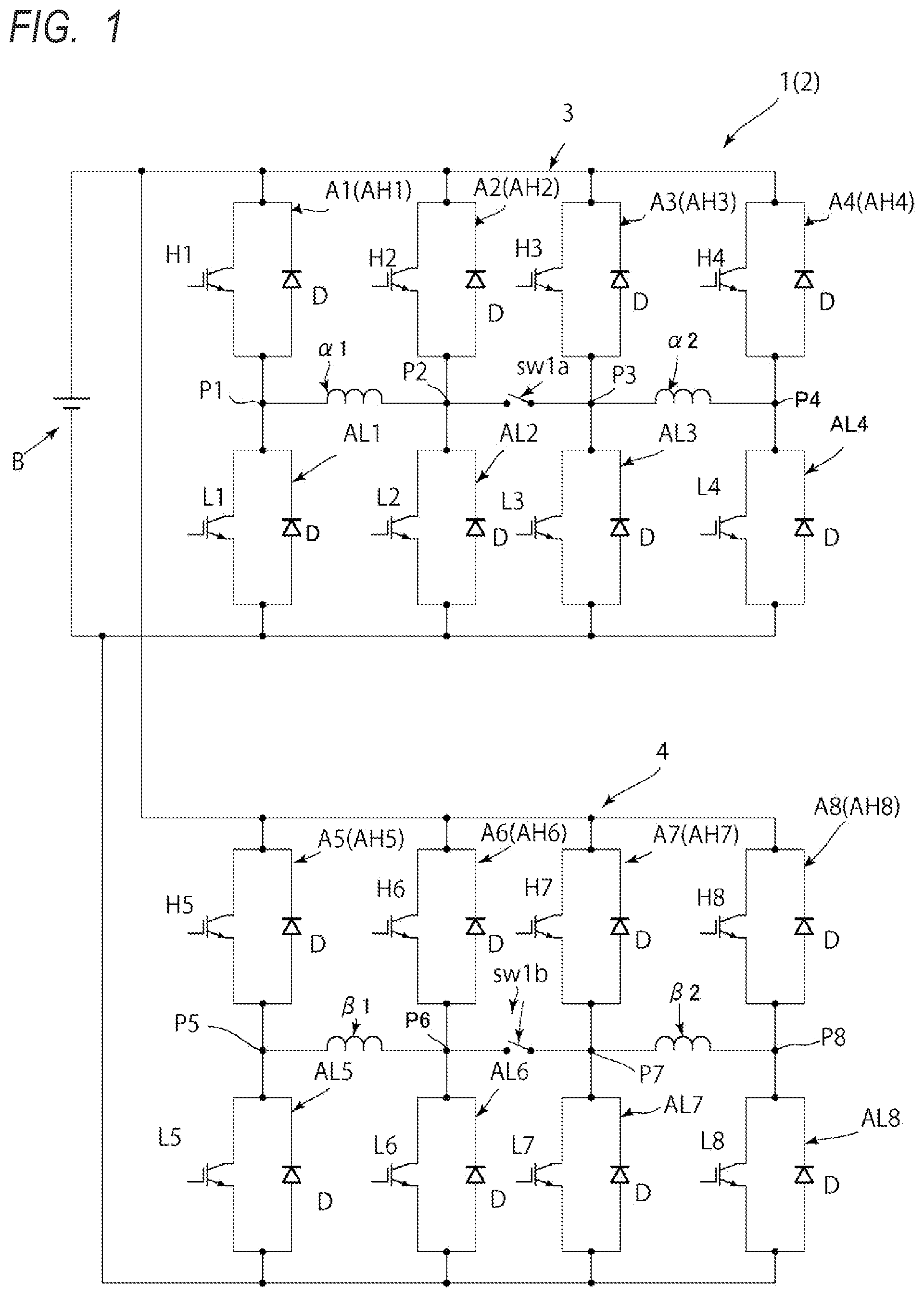
As shown in , a rotary electric machine system 1 includes a rotary electric machine M (see ) and a power supply circuit 2 that supplies electric power to the rotary electric machine.
(Rotary Electric Machine)
As shown in , the rotary electric machine M is a two-phase rotary electric machine including a rotor 10 , a stator 11 , and a first phase winding and a second phase winding β wound around the stator 11 , and is implemented by, for example, a two-phase brushless motor. The first phase winding and the second phase winding β are disposed, for example, on the stator 11 with an electrical angle shifted by 90°. The winding arrangement will be described later. The first phase winding α includes a first winding unit α 1 and a second winding unit α 2 , and the second phase winding β includes a third winding unit β 1 and a fourth winding unit β 2 . The number of turns (also referred to as the turn number in the drawing) of the first winding unit α 1 is equal to the number of turns of the second winding unit α 2 , and the number of turns of the third winding unit β 1 is equal to the number of turns of the fourth winding unit β 2 . The number of turns of the first winding unit α 1 is equal to the number of turns of the third winding unit β 1 , and the number of turns of the second winding unit α 2 is equal to the number of turns of the fourth winding unit β 2 .
(Power Supply Circuit)
The power supply circuit 2 includes a first circuit 3 that is connected to a power supply B and is connected to the first phase winding α, and a second circuit 4 that is connected to the power supply B in parallel with the first circuit 3 and is connected to the second phase winding D.
The first circuit 3 includes first to fourth arms A 1 to A 4 and a first bidirectional switch sw 1 a . The first to fourth arms A 1 to A 4 are connected in parallel to the power supply B.
The first arm A 1 includes an upper arm AH 1 , in which a switching element H 1 and a free wheeling diode D are provided in parallel, and a lower arm AL 1 , in which a switching element L 1 and a free wheeling diode D are provided in parallel, the lower arm AL 1 being connected in series with the upper arm AH 1 via a midpoint P 1 . The second arm A 2 includes an upper arm AH 2 , in which a switching element H 2 and a free wheeling diode D are provided in parallel, and a lower arm AL 2 , in which a switching element L 2 and a free wheeling diode D are provided in parallel, the lower arm AL 2 being connected in series with the upper arm AH 2 via a midpoint P 2 . The third arm A 3 includes an upper arm AH 3 , in which a switching element H 3 and a free wheeling diode D are provided in parallel, and a lower arm AL 3 , in which a switching element L 3 and a free wheeling diode D are provided in parallel, the lower arm AL 3 being connected in series with the upper arm AH 3 via a midpoint P 3 . The fourth arm A 4 includes an upper arm AH 4 , in which a switching element H 4 and a free wheeling diode D are provided in parallel, and a lower arm AL 4 , in which a switching element L 4 and a free wheeling diode D are provided in parallel, the lower arm AL 4 being connected in series with the upper arm AH 4 via a midpoint P 4 .
One end of the first winding unit α 1 is connected to the midpoint P 1 of the first arm A 1 , the other end of the first winding unit α 1 is connected to the midpoint P 2 of the second arm A 2 . One end of the second winding unit α 2 is connected to the midpoint P 3 of the third arm A 3 , and the other end of the second winding unit α 2 is connected to the midpoint P 4 of the fourth arm A 4 .
For example, the first bidirectional switch sw 1 a is configured such that two sets of circuits each including a switching element and a diode in parallel are connected in series in opposite directions (forward directions of the diodes are connected to each other), and a bidirectional current flow can be switched between an ON state and an OFF state based on switching control of the two sets of switching elements. The first bidirectional switch sw 1 a is connected between the midpoint P 2 of the second arm A 2 and the midpoint P 3 of the third arm A 3 .
The second circuit 4 includes fifth to eighth arms A 5 to A 8 and a second bidirectional switch sw 1 b . The fifth to eighth arms A 5 to A 8 of the second circuit 4 are connected in parallel to the power supply B.
The fifth arm A 5 includes an upper arm AH 5 , in which a switching element H 5 and a free wheeling diode D are provided in parallel, and a lower arm AL 5 , in which a switching element L 5 and a free wheeling diode D are provided in parallel, the lower arm AL 5 being connected in series with the upper arm AH 5 via a midpoint P 5 . The sixth arm A 6 includes an upper arm AH 6 , in which a switching element H 6 and a free wheeling diode D are provided in parallel, and a lower arm AL 6 , in which a switching element L 6 and a free wheeling diode D are provided in parallel, the lower arm AL 6 being connected in series with the upper arm AH 6 via a midpoint P 6 . The seventh arm A 7 includes an upper arm AH 7 , in which a switching element H 7 and a free wheeling diode D are provided in parallel, and a lower arm AL 7 , in which a switching element L 7 and a free wheeling diode D are provided in parallel, the lower arm AL 7 being connected in series with the upper arm AH 7 via a midpoint P 7 . The eighth arm A 8 includes an upper arm AH 8 , in which a switching element H 8 and a free wheeling diode D are provided in parallel, and a lower arm AL 8 , in which a switching element L 8 and a free wheeling diode D are provided in parallel, the lower arm AL 8 being connected in series with the upper arm AH 8 via a midpoint P 8 .
One end of the third winding unit β 1 is connected to the midpoint P 5 of the fifth arm A 5 , the other end of the third winding unit β 1 is connected to the midpoint P 6 of the sixth arm A 6 . One end of the fourth winding unit β 2 is connected to the midpoint P 7 of the seventh arm A 7 , and the other end of the fourth winding unit β 2 is connected to the midpoint P 8 of the eighth arm A 8 .
The second bidirectional switch sw 1 b has the same configuration as the first bidirectional switch sw 1 a , and is connected between the midpoint P 6 of the sixth arm A 6 and the midpoint P 7 of the seventh arm A 7 .
Next, an example of the winding arrangement of the rotary electric machine M will be described.
is a diagram showing the example of the winding arrangement of the rotary electric machine M, and is a diagram showing another example of the winding arrangement of the rotary electric machine M. The rotary electric machine M is, for example, a two-phase rotary electric machine having 8 poles and 48 slots.
The rotor 10 is provided with eight magnetic pole units 20 at equal intervals in a circumferential direction. Each of the magnetic pole units 20 is implemented by a permanent magnet 22 provided on a radially outer side of a rotor core 21 . The stator 11 is provided with 48 slots at equal intervals in the circumferential direction on a radially inner side of a stator core 30 . That is, the interval between adjacent slots is 30° in electrical angle. In , only one magnetic pole unit 20 and six slots corresponding to the one magnetic pole unit 20 are shown. In the following description, in , the six slots are referred to as a No. 1 slot S 1 , a No. 2 slot S 2 , a No. 3 slot S 3 , a No. 4 slot S 4 , a No. 5 slot S 5 , and a No. 6 slot S 6 from the right side to the left side in the circumferential direction.
In the example of , six windings (coils) are disposed in each slot. In the No. 1 slot S 1 and the No. 2 slot S 2 , the first winding units α 1 and the second winding units α 2 of the first phase winding α are alternately disposed in a radial direction, respectively. In the No. 4 slot S 4 and the No. 5 slot S 5 , the third winding units β 1 and the fourth winding units β 2 of the second phase winding β are alternately disposed in the radial direction, respectively. In addition, in the No. 3 slot S 3 and the No. 6 slot S 6 , the first winding units α 1 and the second winding units α 2 of the first phase winding α are alternately disposed in the radial direction, and the third winding units α 1 and the fourth winding units α 2 of the second phase winding β are alternately disposed in the radial direction.
As described above, on the stator 11 , the first phase winding α (the first winding unit α 1 and the second winding unit α 2 ) and the second phase winding β (the third winding unit β 1 and the fourth winding unit β 2 ) are disposed with an electrical angle shifted by 90°.
Here, when a slot in which the first winding units α 1 and the second winding units α 2 of the first phase winding α are disposed is referred to as a first slot SL 1 , the No. 1 slot S 1 and the No. 2 slot S 2 constitute the first slot SL 1 . When a slot in which the third winding units β 1 and the fourth winding units β 2 of the second phase winding β are disposed is referred to as a second slot SL 2 , the No. 4 slot S 4 and the No. 5 slot S 5 constitute the second slot SL 2 . When a slot in which all of the first winding units α 1 and the second winding units α 2 of the first phase winding α and the third winding units β 1 and the fourth winding units 12 of the second phase winding β are disposed is referred to as a third slot SL 3 , the No. 3 slot S 3 and the No. 6 slot S 6 constitute the third slot SL 3 .
In the example of , the third slot SL 3 is disposed between the first slot SL 1 and the second slot SL 2 .
In the example of , twelve windings (coils) are disposed in each slot. Only the first winding unit α 1 of the first phase winding α is disposed in the No. 1 slot S 1 , only the second winding unit α 2 of the first phase winding α is disposed in the No. 3 slot S 3 , and the first winding unit α 1 and the second winding unit α 2 of the first phase winding α are disposed in the No. 2 slot S 2 , which is disposed between the No. 1 slot S 1 and the No. 3 slot S 3 , so as to be divided into two in the radial direction. That is, the first winding unit α 1 and the second winding unit α 2 are disposed with an electrical angle shifted by 45°. In addition, only the third winding unit β 1 of the second phase winding β is disposed in the No. 4 slot S 4 , only the fourth winding unit β 2 of the second phase winding β is disposed in the No. 6 slot S 6 , and the third winding unit β 1 and the fourth winding unit β 2 of the second phase winding β are disposed in the No. 5 slot S 5 , which is disposed between the No. 4 slot S 4 and the No. 6 slot S 6 , so as to be divided into two in the radial direction. That is, the third winding unit β 1 and the fourth winding unit β 2 are disposed with an electrical angle shifted by 45°.
As described above, on the stator 11 , the first phase winding α (the first winding unit α 1 and the second winding unit α 2 ) and the second phase winding β (the third winding unit β 1 and the fourth winding unit β 2 ) are disposed with an electrical angle shifted by 90°.
Similarly to the example of , when a slot in which the first winding unit α 1 and the second winding unit α 2 of the first phase winding α are disposed is referred to as the first slot SL 1 , the No. 2 slot S 2 constitutes the first slot SL 1 . When a slot in which the third winding unit β 1 and the fourth winding unit β 2 of the second phase winding β are disposed is referred to as the second slot SL 2 , the No. 5 slot S 5 constitutes the second slot SL 2 . In addition, when a slot, in which only one winding unit is disposed and which is not in the example of , is referred to as a fourth slot SL 4 , the No. 1 slot S 1 , the No. 3 slot S 3 , the No. 4 slot S 4 , and the No. 6 slot S 6 constitute the fourth slot SL 4 .
In the example of , two fourth slots SL 4 are disposed between the first slot SL 1 and the second slot SL 2 . In the example shown in , since the winding units are disposed with an electrical angle shifted by 45°, although in a two-phase motor, the effect of improving a maximum torque and the effect of reducing a torque ripple can be obtained by improving a winding coefficient.
According to the rotary electric machine system 1 configured as described above, the rotary electric machine M can be operated in two modes having different characteristics. Hereinafter, two switchable modes will be described with reference to .
(First Mode)
As shown on the left side of , in a first mode, the first bidirectional switch sw 1 a and the second bidirectional switch sw 1 b are turned on, and based on switching control of the first arm A 1 , the fourth arm A 4 , the fifth arm A 5 , and the eighth arm A 8 , electric power is supplied to the first winding unit α 1 and the second winding unit α 2 of the first phase winding α connected in series and supplied to the third winding unit β 1 and the fourth winding unit β 2 of the second phase winding β connected in series (in , the turn number is described as 2). In the first mode, as shown in the left side of , a torque performance in a low rotation speed region can be improved.
In the example shown in the left side of , in the first embodiment, when the number of turns (the turn number) of the winding of each phase is 18 (18T in the drawing), the number of turns of the first winding unit α 1 and the number of turns of the second winding unit α 2 are 9 (9T in the drawing), and the number of turns of the third winding unit β 1 and the number of turns of the fourth winding unit β 2 are 9 (9T in the drawing).
(Second Mode)
As shown on the right side of , in a second mode, the first bidirectional switch sw 1 a and the second bidirectional switch sw 1 b are turned off, and based on switching control of the first to eighth arms A 1 to A 8 , electric power is supplied to the first winding unit α 1 and the second winding unit α 2 of the first phase winding α connected in parallel and supplied to the third winding unit β 1 and the fourth winding unit β 2 of the second phase winding β connected in parallel (in , the turn number is described as 1). In the second mode, as shown in the left side of , an output performance in a high rotation speed region can be improved. Accordingly, by selecting the first mode in the low rotation speed region and selecting the second mode in the high rotation speed region, both the torque performance and the output performance can be achieved.
(Switching from First Mode to Second Mode)
As shown in , when the mode is shifted from the first mode to the second mode, based on the switching from the ON state of the first bidirectional switch sw 1 a and the second bidirectional switch sw 1 b to the OFF state of the first bidirectional switch sw 1 a and the second bidirectional switch sw 1 b , charges (energy) stored in the winding units α 1 , α 2 , β 1 , and β 2 are discharged. Specifically, in the power supply circuit 2 of the present embodiment, as shown in the right side of , a current flowing through each of the winding units α 1 , α 2 , β 1 , and β 2 flows through the free wheeling diode D of each of the arms A 1 to A 8 . As described above, since paths for releasing the currents of the winding units α 1 , α 2 , β 1 , and β 2 are secured, it is possible to prevent the switching elements H 1 to H 8 , L 1 to L 8 , and the like from being damaged by the currents discharged from the winding units α 1 , α 2 , β 1 , and β 2 .
OTHER EMBODIMENTS
Next, rotary electric machine systems 1 B to 1 E according to second to fifth embodiments will be described with reference to to 10 . However, the same reference numerals as those of the first embodiment are used for configurations common to those of the first embodiment, and the description of the first embodiment may be incorporated.
Second and Third Embodiments
As shown in the center in the left-right direction and the right side of , the rotary electric machine systems 1 B and 1 C of the second and third embodiments are different from those of the first embodiment in that a fifth winding unit α 3 of the first phase winding α is provided between the first bidirectional switch sw 1 a and the midpoint P 3 of the third arm A 3 (or between the midpoint P 2 of the second arm A 2 and the first bidirectional switch sw 1 a ), and a sixth winding unit β 3 of the second phase winding β is provided between the second bidirectional switch sw 1 b and the midpoint P 7 of the seventh arm A 7 (or between the midpoint P 6 of the sixth arm A 6 and the second bidirectional switch sw 1 b ). The number of turns of the fifth winding unit α 3 is equal to the number of turns of the sixth winding unit β 3 . According to the second and third embodiments, as shown in the lower part of , the characteristics of the rotary electric machine M can be greatly changed in the case where electric power is supplied to the three winding units α 1 to α 3 and β 1 to β 3 connected in series (first mode) and the case where electric power is supplied to the two winding units α 1 , α 2 , β 1 , and β 2 connected in parallel (second mode), so that the output efficiency can be further improved.
In the second embodiment, the number of turns of the fifth winding unit α 3 is less than the number of turns of the first winding unit α 1 and the number of turns of the second winding unit α 2 , and the number of turns of the sixth winding unit β 3 is less than the number of turns of the third winding unit β 1 and the number of turns of the fourth winding unit β 2 . In the example shown in the center in the left-right direction of , when the number of turns (the turn number) of the winding of each phase is 18 (18T in the drawing), the number of turns of the fifth winding unit α 3 is 2 (2T in the drawing), the number of turns of the first winding unit α 1 and the number of turns of the second winding unit α 2 are 8 (8T in the drawing), the number of turns of the sixth winding unit β 3 is 2 (2T in the drawing), and the number of turns of the third winding unit β 1 and the number of turns of the fourth winding unit β 2 are 8 (8T in the drawing).
In the third embodiment, the number of turns of the fifth winding unit α 3 is the same as the number of turns of the first winding unit α 1 and the number of turns of the second winding unit α 2 , and the number of turns of the sixth winding unit β 3 is the same as the number of turns of the third winding unit β 1 and the number of turns of the fourth winding unit β 2 . In the example shown in the right side of , when the number of turns (the turn number) of the winding of each phase is 18 (18T in the drawing), the number of turns of the fifth winding unit α 3 , the number of turns of the first winding unit α 1 , and the number of turns of the second winding unit α 2 are 6 (6T in the drawing), and the number of turns of the sixth winding unit β 3 , the number of turns of the third winding unit β 1 , and the number of turns of the fourth winding unit β 2 are 6 (6T in the drawing).
In the second and third embodiments, the power supply circuit 2 is switchable between the first mode and the second mode. In the first mode, the first bidirectional switch sw 1 a and the second bidirectional switch sw 1 b are turned on and electric power is supplied to the first winding unit α 1 , the second winding unit α 2 , and the fifth winding unit α 3 of the first phase winding α connected in series and supplied to the third winding unit β 1 , the fourth winding unit β 2 , and the sixth winding unit β 3 of the second phase winding pi connected in series. In the second mode, the first bidirectional switch sw 1 a and the second bidirectional switch sw 1 b are turned off and electric power is supplied to the first winding unit α 1 and the second winding unit α 2 of the first phase winding α connected in parallel and supplied to the third winding unit β 1 and the fourth winding unit β 2 of the second phase winding β connected in parallel.
In the second and third embodiments, it is preferable that the first circuit 3 and the second circuit 4 are provided with charge release units that release charges (energy) of the fifth winding unit α 3 and the sixth winding unit β 3 when the power supply circuit 2 is switched from the first mode to the second mode. The charge release unit is, for example, a charge release circuit that is connected to both end sides of the fifth winding unit α 3 and the sixth winding unit β 3 and releases the charges (energy) of the fifth winding unit α 3 and the sixth winding unit β 3 in conjunction with switching of the first bidirectional switch sw 1 a and the second bidirectional switch sw 1 b from the ON state to the OFF state. According to such the charge release unit, when the power supply circuit 2 is switched from the first mode to the second mode, generation of a surge current can be prevented by releasing the charges (energy) of the fifth winding unit α 3 and the sixth winding unit β 3 .
In addition, instead of providing the charge release unit, when the power supply circuit 2 is switched from the first mode to the second mode, a period, in which the switching elements H 1 to H 4 and L 1 to L 4 of the first to fourth arms A 1 to A 4 and the switching elements H 5 to H 8 and L 5 to L 8 of the fifth to eighth arms A 5 to A 8 are controlled to be in the OFF state, may be provided. Accordingly, when the power supply circuit 2 is switched from the first mode to the second mode, during the OFF period of each of the switching elements H 1 to H 8 and L 1 to L 8 , the current from the fifth winding unit 3 and the sixth winding unit β 3 flows through the free wheeling diode D of each of the arms A 1 to A 8 , and thus it is possible to release the charges (energy) of the fifth winding unit α 3 and the sixth winding unit β 3 without separately providing a charge release circuit.
Fourth Embodiment
As shown in , the rotary electric machine system 1 D of the fourth embodiment is different from those of the second and third embodiments in that the rotary electric machine system 1 D further includes a third bidirectional switch sw 2 a provided between the first winding unit α 1 of the first phase winding α and the midpoint P 2 of the second arm A 2 (or between the first winding unit α 1 of the first phase winding α and the midpoint P 1 of the first arm A 1 ), a fourth bidirectional switch sw 2 b provided between the third winding unit β 1 of the second phase winding β and the midpoint P 6 of the sixth arm A 6 (or between the third winding unit β 1 of the second phase winding β and the midpoint P 5 of the fifth arm A 5 ), a fifth bidirectional switch sw 3 a provided between the second winding unit α 2 of the first phase winding α and the midpoint P 4 of the fourth arm A 4 (or between the second winding unit α 2 of the first phase winding α and the midpoint P 3 of the third arm A 3 ), and a sixth bidirectional switch sw 3 b provided between the fourth winding unit β 2 of the second phase winding β and the midpoint P 8 of the eighth arm A 8 (or between the fourth winding unit β 2 of the second phase winding β and the midpoint P 7 of the seventh arm A 7 ).
According to the fourth embodiment, four modes (eleventh mode to fourteenth mode) as shown in can be implemented. In the example shown in , when the number of turns (the turn number) of the winding of each phase is 18 (18T in the drawing), the number of turns of the fifth winding unit α 3 is 10 (10T in the drawing), the number of turns of the first winding unit α 1 and the number of turns of the second winding unit α 2 are 4 (4T in the drawing), the number of turns of the sixth winding unit β 3 is 10 (10T in the drawing), and the number of turns of the third winding unit β 1 and the number of turns of the fourth winding unit β 2 are 4 (4T in the drawing).
Eleventh Mode
As shown in the left end of , in the eleventh mode, the first bidirectional switch sw 1 a , the second bidirectional switch sw 1 b , the third bidirectional switch sw 2 a , the fourth bidirectional switch sw 2 b , the fifth bidirectional switch sw 3 a , and the sixth bidirectional switch sw 3 b are turned on, and based on switching control of the first arm A 1 , the seventh arm A 7 , the fourth arm A 4 , and the eighth arm A 8 , electric power is supplied to the first winding unit α 1 , the fifth winding unit 3 , and the second winding unit α 2 of the first phase winding α and the third winding unit β 1 , the sixth winding unit β 3 , and the fourth winding unit β 2 of the second phase winding β, which are connected in series. That is, the number of turns (the turn number) of the winding of each phase to which electric power is supplied is 18 (18T in the drawing).
Twelfth Mode
As shown in the second column from the left end in , in the twelfth mode, the first bidirectional switch sw 1 a , the second bidirectional switch sw 1 b , the third bidirectional switch sw 2 a , and the fourth bidirectional switch sw 2 b are turned on, the fifth bidirectional switch sw 3 a and the sixth bidirectional switch sw 3 b are turned off, and based on switching control of the first arm A 1 , the third arm A 3 , the fifth arm A 5 , and the seventh arm A 7 , electric power is supplied to the first winding unit α 1 and the fifth winding unit α 3 of the first phase winding α connected in series and to the third winding unit β 1 and the sixth winding unit β 3 of the second phase winding β connected in series. That is, the number of turns (the turn number) of the winding of each phase to which electric power is supplied is 14 (14T in the drawing).
Thirteenth Mode
As shown in the third column from the left end of , in the thirteenth mode, the first bidirectional switch sw 1 a and the second bidirectional switch sw 1 b are turned on, the third bidirectional switch sw 2 a , the fourth bidirectional switch sw 2 b , the fifth bidirectional switch sw 3 a , and the sixth bidirectional switch sw 3 b are turned off, and based on switching control of the second arm A 2 , the third arm A 3 , the sixth arm A 6 , and the seventh arm A 7 , electric power is supplied to the fifth winding unit α 3 of the first phase winding α and the sixth winding unit β 3 of the second phase winding β. That is, the number of turns (the turn number) of the winding of each phase to which electric power is supplied is 10 (10T in the drawing).
Fourteenth Mode
As shown in the right side of , in the fourteenth mode, the third bidirectional switch sw 2 a , the fourth bidirectional switch sw 2 b , the fifth bidirectional switch sw 3 a , and the sixth bidirectional switch sw 3 b are turned on, the first bidirectional switch sw 1 a and the second bidirectional switch sw 1 b are turned off, and based on switching control of the first to eighth arms A 1 to A 8 , electric power is supplied to the first winding unit α 1 and the second winding unit α 2 of the first phase winding α connected in parallel and to the third winding unit β 1 and the fourth winding unit β 2 of the second phase winding β connected in parallel. In this case, two circuits having the number of turns (the turn number) of four to which electric power is supplied are present in parallel in the winding of each phase (4T 2para in the drawing).
According to the fourth embodiment as described above, as shown in , since more characteristics can be imparted to the rotary electric machine M as compared with the first to third embodiments, the output efficiency can be further improved.
(Modification of Fourth Embodiment)
shows a modification of the fourth embodiment, in which the third bidirectional switch sw 2 a is provided between the switching element H 1 of the upper arm AH 1 and the switching element L 1 of the lower arm AL 1 of the first arm A 1 , and the fourth bidirectional switch sw 2 b is provided between the switching element H 5 of the upper arm AH 5 and the switching element L 5 of the lower arm AL 5 of the fifth arm A 5 . In addition, the fifth bidirectional switch sw 3 a is provided between the switching element H 4 of the upper arm AH 4 and the switching element L 4 of the lower arm AL 4 of the fourth arm A 4 , and the sixth bidirectional switch sw 3 b is provided between the switching element H 8 of the upper arm AH 8 and the switching element L 8 of the lower arm AL 8 of the eighth arm A 8 . With such a configuration of the modification, four modes can be implemented similarly to the fourth embodiment described above.
Fifth Embodiment
The rotary electric machine system 1 E of the fifth embodiment shown in is different from the first to fourth embodiments in that the rotary electric machine system 1 E is applied to a three-phase rotary electric machine.
As shown in , the power supply circuit 2 of the fifth embodiment supplies electric power to the rotary electric machine M, which includes the first phase (U phase) winding α including the first winding unit α 1 and the second winding unit α 2 , the second phase (V phase) winding β including the third winding unit β 1 and the fourth winding unit β 2 , and a third phase (W phase) winding γ including a seventh winding unit γ 1 and an eighth winding unit γ 2 .
The power supply circuit 2 includes a third circuit 5 in addition to the first circuit 3 and the second circuit 4 described above. The third circuit 5 is connected to the power supply B in parallel with the first circuit 3 and the second circuit 4 , and is connected to the third phase winding γ.
The third circuit 5 includes ninth to twelfth arms A 9 to A 12 and a seventh bidirectional switch sw 1 c . The ninth to twelfth arms A 9 to A 12 of the third circuit 5 are connected in parallel to the power supply B.
The ninth arm A 9 includes an upper arm AH 9 , in which a switching element H 9 and a free wheeling diode D are provided in parallel, and a lower arm AL 9 , in which a switching element L 9 and a free wheeling diode D are provided in parallel, the lower arm AL 9 being connected in series with the upper arm AH 9 via a midpoint P 9 . The tenth arm A 10 includes an upper arm AH 10 , in which a switching element H 10 and a free wheeling diode D are provided in parallel, and a lower arm AL 10 , in which a switching element L 10 and a free wheeling diode D are provided in parallel, the lower arm AL 10 being connected in series with the upper arm AH 10 via a midpoint P 10 . The eleventh arm A 11 includes an upper arm AH 11 , in which a switching element H 11 and a free wheeling diode D are provided in parallel, and a lower arm AL 11 , in which a switching element L 11 and a free wheeling diode D are provided in parallel, the lower arm AL 11 being connected in series with the upper arm AH 11 via a midpoint P 11 . The twelfth arm A 12 includes an upper arm AH 12 , in which a switching element H 12 and a free wheeling diode D are provided in parallel, and a lower arm AL 12 , in which a switching element L 12 and a free wheeling diode D are provided in parallel, the lower arm AL 12 being connected in series with the upper arm AH 12 via a midpoint P 12 .
One end of the seventh winding unit γ 1 is connected to the midpoint P 9 of the ninth arm A 9 , the other end of the seventh winding unit γ 1 is connected to the midpoint P 10 of the tenth arm A 10 . One end of the eighth winding unit γ 2 is connected to the midpoint P 11 of the eleventh arm A 11 , and the other end of the eighth winding unit γ 2 is connected to the midpoint P 12 of the twelfth arm A 12 .
The seventh bidirectional switch sw 1 c has the same configuration as the first bidirectional switch sw 1 a and the like, and is connected between the midpoint P 10 of the tenth arm A 10 and the midpoint P 11 of the eleventh arm A 11 .
According to the fifth embodiment, even in the three-phase rotary electric machine, when electric power is supplied to the windings α, β, and γ of the respective phases, the rotary electric machine M can have different characteristics by switching between a case where electric power is supplied to two winding units connected in series and a case where electric power is supplied to two winding units connected in parallel. Accordingly, an efficient operating point can be selected, and thus output efficiency can be improved.
In addition, in the fifth embodiment, as in the second and third embodiments, a winding unit may be provided in series with the bidirectional switches sw 1 a , sw 1 b , and sw 1 c . Further, also in the fifth embodiment, as in the fourth embodiment, a bidirectional switch may be provided between each winding unit and the midpoint.
Although various embodiments have been described above with reference to the drawings, it is needless to say that the present invention is not limited to these examples. It is apparent to those skilled in the art that various changes and modifications can be conceived within the scope of the claims, and it is also understood that such variations and modifications belong to the technical scope of the present invention. In addition, constituent elements in the embodiments described above may be combined freely within a range not departing from the spirit of the present invention.
For example, the bidirectional switch may be a contactor mechanical switch, a reverse blocking IGBT, and the like as long as the bidirectional switch is capable of blocking the flow of the bidirectional current.
The present specification describes at least the following matters. Although the corresponding constituent elements and the like in the above embodiment are shown in parentheses, the present invention is not limited thereto.
(1) A power supply circuit (power supply circuit 2 ) configured to supply electric power to a rotary electric machine (rotary electric machine M) including a first phase winding (first phase winding α) and a second phase winding, the first phase winding including a first winding unit (first winding unit α 1 ) and a second winding unit (second winding unit α 2 ), and the second phase winding (second phase winding β) including a third winding unit (third winding unit β 1 ) and a fourth winding unit (fourth winding unit β 2 ),
•
• the power supply circuit including: • a first circuit (first circuit 3 ) that is connectable to a power supply (power supply B) and is connected to the first phase winding; and • a second circuit (second circuit 4 ) that is connectable to the power supply in parallel with the first circuit and is connected to the second phase winding, in which • the first circuit includes: first to fourth arms (first to fourth arms A 1 to A 4 ) in each of which an upper arm (upper arms AH 1 to AH 4 ) provided with a switching element (switching elements H 1 to H 4 ) and a lower arm (AL 1 to AL 4 ) provided with a switching element (switching elements L 1 to L 4 ) are connected at a midpoint (midpoints P 1 to P 4 ) of each arm; and a first switch (first bidirectional switch sw 1 a ). • the midpoint of the first arm is connected to one end of the first winding unit, • the midpoint of the second arm is connected to another end of the first winding unit, • the midpoint of the third arm is connected to one end of the second winding unit, • the midpoint of the fourth arm is connected to another end of the second winding unit, • the first switch is connected between the midpoint of the second arm and the midpoint of the third arm, • the second circuit includes: fifth to eighth arms (fifth to eighth arms A 5 to A 8 ) in each of which an upper arm (upper arms AH 5 to AH 8 ) provided with a switching element (switching elements H 5 to H 8 ) and a lower arm (lower arms AL 5 to AL 8 ) provided with a switching element (switching elements L 5 to L 8 ) are connected at a midpoint (midpoints P 5 to P 8 ) of each arm; and a second switch (second bidirectional switch sw 1 b ), • the midpoint of the fifth arm is connected to one end of the third winding unit, • the midpoint of the sixth arm is connected to another end of the third winding unit, • the midpoint of the seventh arm is connected to one end of the fourth winding unit, • the midpoint of the eighth arm is connected to another end of the fourth winding unit, and • the second switch is connected between the midpoint of the sixth arm and the midpoint of the seventh arm.
According to (1), in a multi-phase rotary electric machine, when electric power is supplied to the windings of the respective phases, the rotary electric machine can have different characteristics by switching between a case where electric power is supplied to two winding units connected in series and a case where electric power is supplied to two winding units connected in parallel. Accordingly, an efficient operating point can be selected, and thus output efficiency can be improved.
(2) The power supply circuit according to (1), in which
•
• the power supply circuit is switchable between a first mode and a second mode, in which the first mode is a mode in which the first switch and the second switch are turned on and electric power is supplied to the first winding unit and the second winding unit of the first phase winding connected in series and supplied to the third winding unit and the fourth winding unit of the second phase winding connected in series, and the second mode is a mode in which the first switch and the second switch are turned off and electric power is supplied to the first winding unit and the second winding unit of the first phase winding connected in parallel and supplied to the third winding unit and the fourth winding unit of the second phase winding connected in parallel.
According to (2), by selecting the first mode in a low rotation speed region and selecting the second mode in a high rotation speed region, it is possible to achieve both a torque density and an output density.
(3) The power supply circuit according to (2), in which
•
• the first to fourth arms include free wheeling diodes (free wheeling diode D) each of which is provided in parallel with the corresponding switching element, and • when the power supply circuit is switched from the first mode to the second mode, a current flowing through the first winding unit and the second winding unit of the first phase winding flows through the free wheeling diodes.
According to (3), it is possible to prevent the switching elements and the like from being damaged by the currents discharged from the first winding unit and the second winding unit.
(4) The power supply circuit according to (2) or (3), in which
•
• the fifth to eighth arms include free wheeling diodes (free wheeling diode D) each of which is provided in parallel with the corresponding switching element, and • when the power supply circuit is switched from the first mode to the second mode, a current flowing through the third winding unit and the fourth winding unit of the second phase winding flows through the free wheeling diodes.
According to (4), it is possible to prevent the switching elements and the like from being damaged by the currents discharged from the third winding unit and the fourth winding unit.
(5) The power supply circuit according to any one of (1) to (4), in which
•
• a fifth winding unit (fifth winding unit α 3 ) of the first phase winding is provided between the midpoint of the second arm and the first switch or between the first switch and the midpoint of the third arm, and • a sixth winding unit (sixth winding unit β 3 ) of the second phase winding is provided between the midpoint of the sixth arm and the second switch or between the second switch and the midpoint of the seventh arm.
According to (5), the characteristics of the rotary electric machine can be greatly changed in a case where electric power is supplied to three winding units connected in series and a case where electric power is supplied to two winding units connected in parallel, and the output efficiency can be further improved.
(6) The power supply circuit according to (5), in which
•
• the number of turns of the first winding unit is equal to the number of turns of the second winding unit, • the number of turns of the fifth winding unit is equal to or larger than the number of turns of the first winding unit and the number of turns of the second winding unit, • the number of turns of the third winding unit is equal to the number of turns of the fourth winding unit, and • the number of turns of the sixth winding unit is equal to or larger than the number of turns of the third winding unit and the number of turns of the fourth winding unit.
According to (6), a difference in the number of turns of the winding to which the electric power is supplied increases in a case where electric power is supplied to three winding units connected in series and a case where electric power is supplied to two winding units connected in parallel.
(7) The power supply circuit according to (5) or (6), in which
•
• the first to fourth arms include free wheeling diodes each of which is provided in parallel with the corresponding switching element, • the fifth to eighth arms included free wheeling diodes each of which is provided in parallel with the corresponding switching element, • the power supply circuit is switchable between a first mode and a second mode, in which the first mode is a mode in which the first switch and the second switch are turned on and electric power is supplied to the first winding unit, the second winding unit, and the fifth winding unit of the first phase winding connected in series and supplied to the third winding unit, the fourth winding unit, and the sixth winding unit of the second phase winding connected in series, and the second mode is a mode in which the first switch and the second switch are turned off and electric power is supplied to the first winding unit and the second winding unit of the first phase winding connected in parallel and supplied to the third winding unit and the fourth winding unit of the second phase winding connected in parallel, and • when the power supply circuit is switched from the first mode to the second mode, a current flowing through the fifth winding unit flows through the free wheeling diodes of the first to fourth arms and a current flowing through the sixth winding unit flows through the free wheeling diodes of the fifth to eighth arms.
According to (7), in the first mode, since the number of turns of the winding to which the electric power is supplied is large, a torque is improved, an inductance is increased, a harmonic component of the current is reduced, and an iron loss is reduced. On the other hand, in the second mode, since the number of turns of the winding to which the electric power is supplied is small, magnetic flux is reduced so as to reduce a counter-electromotive force, and an output on a high rotation speed side can be improved. In addition, when the power supply circuit is switched from the first mode to the second mode, the current flowing through the fifth winding unit and the sixth winding unit flows through the free wheeling diodes, and thus it is possible to prevent generation of a surge current.
(8) The power supply circuit according to (7), in which
•
• when the power supply circuit is switched from the first mode to the second mode, • a period, in which the switching element of the first to fourth arms and the switching element of the fifth to eighth arms are controlled to be in an OFF state, is provided.
According to (8), when the power supply circuit is switched from the first mode to the second mode, during the OFF period of each switching element, the current from the fifth winding unit and the sixth winding unit flows through the free wheeling diodes, and thus it is possible to release charges (energy) of the fifth winding unit and the sixth winding unit.
(9) The power supply circuit according to any one of (1) to (4), in which
•
• the rotary electric machine includes a stator (stator 11 ) and a rotor (rotor 10 ), • the stator includes a plurality of slots (slots S 1 to S 6 ) disposed side by side in a circumferential direction, • the plurality of slots include a first slot (first slot SL 1 ) and a second slot (second slot SL 2 ) that are disposed apart from each other in the circumferential direction, • the first winding unit and the second winding unit are disposed in the first slot, and • the third winding unit and the fourth winding unit are disposed in the second slot.
(10) The power supply circuit according to (9), in which
•
• the plurality of slots include a third slot (third slot SL 3 ) disposed between the first slot and the second slot, and • the first winding unit, the second winding unit, the third winding unit, and the fourth winding unit are disposed in the third slot.
(11) The power supply circuit according to (9), in which
•
• the plurality of slots include a fourth slot (fourth slot SL 4 ) disposed between the first slot and the second slot, and • only one of the first winding unit, the second winding unit, the third winding unit, and the fourth winding unit is disposed in the fourth slot.
(12) The power supply circuit according to (11), in which
•
• the first winding unit and the second winding unit are disposed with an electrical angle shifted by 45°, and • the third winding unit and the fourth winding unit are disposed with an electrical angle shifted by 45°.
According to (12), when electric power is supplied to two winding units connected in parallel, since the winding units are disposed with an electrical angle shifted by 45°, although in a two-phase motor, the effect of improving a maximum torque and the effect of reducing a torque ripple can be obtained by improving a winding coefficient.
(13) The power supply circuit according to any one of (9) to (12), in which
•
• the first winding unit and the second winding unit, and the third winding unit and the fourth winding unit are disposed with an electrical angle shifted by 90°.
(14) The power supply circuit according to (1),
•
• the rotary electric machine (rotary electric machine M) further including a third phase winding (third phase winding γ) which includes a seventh winding unit (seventh winding unit γ 1 ) and an eighth winding unit (eighth winding unit γ 2 ), the power supply circuit further including: • a third circuit (third circuit 5 ) that is connectable to the power supply in parallel with the first circuit and the second circuit and is connected to the third phase winding, in which • the third circuit includes: ninth to twelfth arms (ninth to twelfth arms A 9 to A 12 ) in each of which an upper arm (upper arms AH 9 to AH 12 ) provided with a switching element (switching elements H 9 to H 12 ) and a lower arm (lower arms AL 9 to AL 12 ) provided with a switching element (switching elements L 9 to L 12 ) are connected at a midpoint (midpoints P 9 to P 12 ) of each arm; and a third switch (seventh bidirectional switch sw 1 c ), • the midpoint of the ninth arm is connected to one end of the seventh winding unit, • the midpoint of the tenth arm is connected to another end of the seventh winding unit, • the midpoint of the eleventh arm is connected to one end of the eighth winding unit, • the midpoint of the twelfth arm is connected to another end of the eighth winding unit, and • the third switch is connected between the midpoint of the tenth arm and the midpoint of the eleventh arm.
According to (14), in a three-phase rotary electric machine, when electric power is supplied to the windings of the respective phases, the rotary electric machine can have different characteristics by switching between a case where electric power is supplied to two winding units connected in series and a case where electric power is supplied to two winding units connected in parallel. Accordingly, an efficient operating point can be selected, and thus output efficiency can be improved.
(15) A rotary electric machine system (rotary electric machine system 1 ) including:
•
• a rotary electric machine (rotary electric machine M) including a first phase winding (first phase winding α) and a second phase winding (second phase winding β); and • a power supply circuit (power supply circuit 2 ) configured to supply electric power to the rotary electric machine, in which • the first phase winding includes a first winding unit (first winding unit α 1 ) and a second winding unit (second winding unit α 2 ), • the second phase winding includes a third winding unit (third winding unit β 1 ) and a fourth winding unit (fourth winding unit β 2 ), • the power supply circuit includes
• a first circuit (first circuit 3 ) that is connected to a power supply (power supply B) and is connected to the first phase winding, and • a second circuit (second circuit 4 ) that is connected to the power supply in parallel with the first circuit and is connected to the second phase winding, • the first circuit includes: first to fourth arms (first to fourth arms A 1 to A 4 ) in each of which an upper arm (upper arms AH 1 to AH 4 ) provided with a switching element (switching elements H 1 to H 4 ) and a lower arm (lower arms AL 1 to AL 4 ) provided with a switching element (switching elements L 1 to L 4 ) are connected at a midpoint (midpoints P 1 to P 4 ) of each arm; and a first switch (first bidirectional switch sw 1 a ), • the midpoint of the first arm is connected to one end of the first winding unit, • the midpoint of the second arm is connected to another end of the first winding unit, • the midpoint of the third arm is connected to one end of the second winding unit, • the midpoint of the fourth arm is connected to another end of the second winding unit, • the first switch is connected between the midpoint of the second arm and the midpoint of the third arm, • the second circuit includes: fifth to eighth arms (fifth to eighth arms A 5 to A 8 ) in each of which an upper arm (upper arms AH 5 to AH 8 ) provided with a switching element (switching elements H 5 to H 8 ) and a lower arm (lower arms AL 5 to AL 8 ) provided with a switching element (switching elements L 5 to L 8 ) are connected at a midpoint (midpoints P 5 to P 8 ) of each arm; and a second switch (second bidirectional switch sw 1 b ), • the midpoint of the fifth arm is connected to one end of the third winding unit, • the midpoint of the sixth arm is connected to another end of the third winding unit, • the midpoint of the seventh arm is connected to one end of the fourth winding unit, • the midpoint of the eighth arm is connected to another end of the fourth winding unit, and • the second switch is connected between the midpoint of the sixth arm and the midpoint of the seventh arm.
According to (15), in a multi-phase rotary electric machine, when electric power is supplied to the windings of the respective phases, the rotary electric machine can have different characteristics by switching between a case where electric power is supplied to two winding units connected in series and a case where electric power is supplied to two winding units connected in parallel. Accordingly, an efficient operating point can be selected, and thus output efficiency can be improved.
Figures (12)
Citations
This patent cites (8)
- US5969919
- US20200395875
- USH11-098888
- US2011045181
- US2011-244576
- US2019146383
- USWO 2019/155756
- USWO 2019/163025