Abstract
To provide a coaxial flat cable that can achieve stable high-frequency transmission characteristics as a structure by which stress is not applied to a specific coaxial cable, even due to handling of the coaxial flat cable or the like. The above-described problem is solved by a coaxial flat cable ( 20 ) comprising a plurality of coaxial cables ( 10 ) disposed side by side in a width direction (X), and a resin tape ( 11 ) integrating at least terminal parts ( 21 ) of these coaxial cables ( 10 ) from one surface or both surfaces, each of the plurality of coaxial cables ( 10 ) being connected by soldering to a substrate ( 30 ) or a connector. The resin tape ( 11 ) positioned at the terminal parts ( 21 ) is configured to be provided with a fixed part ( 21 a ), to be fixed to the substrate or the connector, at both end portions in the width direction (X).
Claims (8)
1. A coaxial flat cable comprising: a plurality of coaxial cables disposed side by side in a width direction; and a resin tape bonded to at least terminal parts of the plurality of coaxial cables from one surface or both surfaces to integrate the terminal parts, each of the plurality of coaxial cables being connected by soldering to a substrate or a connector, and of the resin tape, the resin tape positioned at the terminal parts being provided with a fixed part, to be fixed to the substrate or the connector, at both end portions in the width direction, wherein the resin tape is a reinforcing tape provided to the terminal parts of the plurality of the coaxial cables, and the fixed part is provided to the reinforcing tape.
5. A coaxial flat cable comprising: a plurality of coaxial cables disposed side by side in a width direction; and a resin tape bonded to at least terminal parts of the plurality of coaxial cables from one surface or both surfaces to integrate the terminal parts, each of the plurality of coaxial cables being connected by soldering to a substrate or a connector, and of the resin tape, the resin tape positioned at the terminal parts being provided with a fixed part, to be fixed to the substrate or the connector, at both end portions in the width direction, wherein the resin tape is a cover tape that sandwiches and integrates the plurality of coaxial cables fully from both surfaces, and a reinforcing tape is bonded to one surface of the cover tape at the terminal parts of the plurality of coaxial cables, and wherein the fixed part is provided to the cover tape and to a bonding part of the reinforcing tape.
Show 6 dependent claims
2. The coaxial flat cable according to claim 1 , wherein the fixed part comprises a hole or a projection fitted to a fitting part provided on the substrate or the connector.
3. The coaxial flat cable according to claim 1 , wherein the fixed part comprises a notch fitted to a fitting part provided on the substrate or the connector.
4. The coaxial flat cable according to claim 1 , wherein the plurality of coaxial cables each include at least a center conductor, an insulator provided on an outer periphery of the center conductor, an external conductor provided on an outer periphery of the insulator, and an outer coated body provided on an outer periphery of the external conductor, and areas connected by soldering to the substrate or the connector are the center conductor and the external conductor.
6. The coaxial flat cable according to claim 5 , wherein the fixed part comprises a hole or a projection fitted to a fitting part provided on the substrate or the connector.
7. The coaxial flat cable according to claim 5 , wherein the fixed part comprises a notch fitted to a fitting part provided on the substrate or the connector.
8. The coaxial flat cable according to claim 5 , wherein the plurality of coaxial cables each include at least a center conductor, an insulator provided on an outer periphery of the center conductor, an external conductor provided on an outer periphery of the insulator, and an outer coated body provided on an outer periphery of the external conductor, and areas connected by soldering to the substrate or the connector are the center conductor and the external conductor.
Full Description
Show full text →
CROSS REFERENCE TO RELATED APPLICATIONS
This application is a National Stage of International Application No. PCT/JP2020/046606 filed Dec. 14, 2020, claiming priority based on Japanese Patent Application No. 2020-075520 filed Apr. 21, 2020.
FIELD OF THE INVENTION
The present invention relates to a coaxial flat cable, and more particularly to a coaxial flat cable used in or between electronic devices such as a liquid crystal television or a server, and configured so that stress is not applied to a specific coaxial cable, even due to handling or the like.
BACKGROUND ART
A flat cable has excellent processability and flexibility, and is widely used as an internal wiring material or an external wiring material in an electronic device. As a flat cable particularly suitable for propagating high-frequency signals, coaxial flat cables that utilize a plurality of coaxial cables have been proposed. For example, Patent Document 1 proposes a coaxial flat cable that has a large center conductor diameter and a small finished outer diameter, and exhibits stable high-frequency characteristics. This coaxial flat cable is a coaxial flat cable including a plurality of coaxial cables disposed in parallel at regular intervals and a fixing tape that integrates at least terminal parts of the plurality of coaxial cables from one surface or both surfaces, the coaxial cables each including at least a center conductor, a dielectric layer provided on an outer periphery of the center conductor and including a void part continuous in a longitudinal direction, an external conductor provided on an outer periphery of the dielectric layer, and an insulating layer provided on an outer periphery of the external conductor.
PRIOR ART DOCUMENTS
Patent Documents
•
• Patent Document 1: Japanese Laid-Open Patent Application Publication No. 2019-67518
SUMMARY OF THE INVENTION
Problems to be Solved by the Invention
The coaxial cables constituting the conventional coaxial flat cable described above are respectively soldered to a substrate at the external conductor and the center conductor. Nevertheless, in a case in which stress is applied to a specific coaxial cable due to handling after soldering or the like, the stress may concentrate on soldered parts of the external conductor and the center conductor, resulting in damage at the soldered parts. Damage at the soldered parts can cause deterioration in the high-frequency transmission characteristics of the coaxial flat cable.
The present invention was made to solve the problems described above, and an object thereof is to provide a coaxial flat cable configured so that stress is not applied to a specific coaxial cable, even due to handling of the coaxial flat cable or the like.
Means for Solving the Problems
A coaxial flat cable according to the present invention is a coaxial flat cable comprising a plurality of coaxial cables disposed side by side in a width direction, and a resin tape bonded to at least terminal parts of the plurality of coaxial cables from one surface or both surfaces to integrate the terminal parts, each of the plurality of coaxial cables being connected by soldering to a substrate or a connector. Of the resin tape, the resin tape positioned at the terminal parts is provided with a fixed part, to be fixed to the substrate or the connector, at both end portions in the width direction.
According to this invention, of the resin tape bonded to at least the terminal parts from one surface or both surfaces, the resin tape positioned at the terminal parts is provided with the fixed part, fixed (engaged, fitted, crimped, caulked, or the like) to the substrate or the connector, at both end portions in the width direction, making it possible to receive the applied stress across the entire resin tape and thus prevent stress from being applied to a specific coaxial cable. As a result, stress concentration on the soldered connection parts of a specific external conductor or center conductor is eliminated, making it possible to prevent damage at the soldered connection parts. It should be noted that the term “at least” means that the resin tape is always provided at the terminal parts, but the resin tape may be provided in a middle part other than the terminal parts as well.
In the coaxial flat cable according to the present invention, the fixed part is a hole or a projection fitted to a fitting part provided on the substrate or the connector.
According to this invention, the fixed part is a hole or a projection, and thus the hole or the projection is fitted into the fitting part provided on the substrate or the connector, fixing the coaxial flat cable to the substrate or the connector.
In the coaxial flat cable according to the present invention, the fixed part is a notch fitted to a fitting part provided on the substrate or the connector.
According to this invention, the fixed part is a notch, and thus the notch is fitted into the fitting part provided on the substrate or the connector, fixing the coaxial flat cable to the substrate or the connector.
In the coaxial flat cable according to the present invention, (1) in a case in which the resin tape is a cover tape that sandwiches and integrates the plurality of coaxial cables fully from both surfaces, a convex portion or a concave portion is provided to the cover tape. (2) In a case in which the resin tape is a reinforcing tape provided to the terminal parts of the plurality of coaxial cables, a convex portion or a concave portion is provided to the reinforcing tape. (3) In a case in which the resin tape is a cover tape that sandwiches and integrates the plurality of coaxial cables fully from both surfaces, and a reinforcing tape bonded to one surface of the cover tape at the terminal parts of the plurality of coaxial cables, a convex portion or a concave portion is provided to the cover tape and to a bonding part of the reinforcing tape.
According to these aspects of the present invention, in a case in which the resin tape is a cover tape, a reinforcing tape, or a combination of a cover tape and a reinforcing tape, the fixed part is provided to these, thereby fixing the coaxial flat cable to the substrate or the connector.
In the coaxial flat cable according to the present invention, the plurality of coaxial cables each include at least a center conductor, an insulator provided on an outer periphery of the center conductor, an external conductor provided on an outer periphery of the insulator, and an outer coated body provided on an outer periphery of the external conductor. Areas connected by soldering to the substrate or the connector are the center conductor and the external conductor. In this case, the insulator is any one of a solid structure, a hollow structure, or a foam structure, and is preferably a hollow structure.
According to this invention, stress concentration on a specific center conductor or external conductor connected by soldering to the substrate or the connector is eliminated, making it possible to prevent damage at the soldered connection parts.
Effect of the Invention
According to the present invention, it is possible to provide a coaxial flat cable used in or between electronic devices such as a liquid crystal television or a server, and configured so that stress is not applied to a specific coaxial cable, even due to handling of the coaxial flat cable or the like. In particular, it is possible to receive applied stress across the entire resin tape and prevent stress from being applied to a specific coaxial cable, and thus stress concentration on the soldered connection parts of a specific external conductor or center conductor is eliminated, making it possible to prevent damage at the soldered connection parts.
BRIEF DESCRIPTION OF THE DRAWINGS
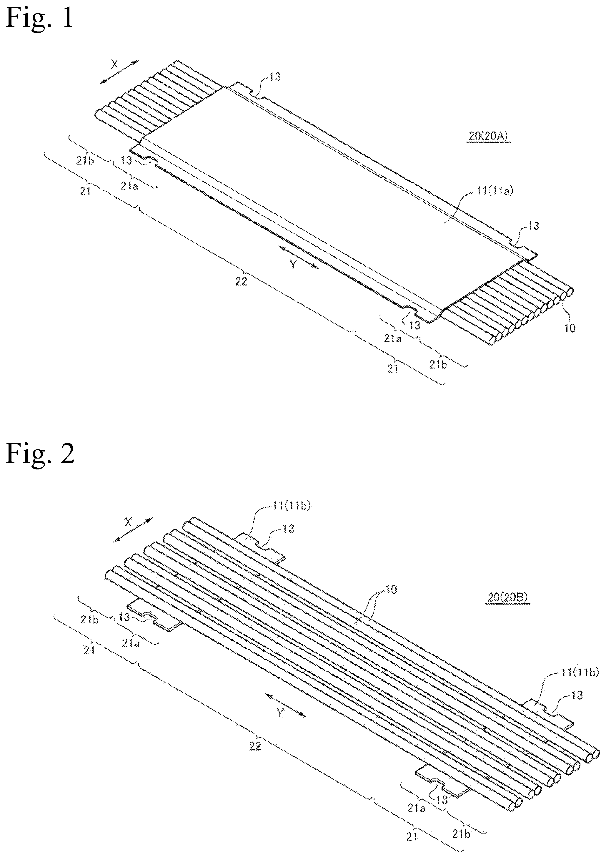
is a perspective view illustrating an example of a coaxial flat cable according to the present invention.
is a perspective view illustrating another example of the coaxial flat cable according to the present invention.
is a perspective view illustrating another example of the coaxial flat cable according to the present invention.
is a perspective view illustrating another example of the coaxial flat cable according to the present invention.
is a perspective view illustrating another example of the coaxial flat cable according to the present invention.
is a perspective view illustrating another example of the coaxial flat cable according to the present invention.
A to 7 C are cross-sectional views of coaxial flat cables, A being the coaxial flat cable in , B being the coaxial flat cable in , and C being the coaxial flat cable in .
A and 8 B are cross-sectional views of coaxial cables constituting a coaxial flat cable, A being an example of a solid insulator and B being an example of a hollow insulator.
is a plan view illustrating a form of a coaxial flat cable after terminal processing.
A and 10 B are a plan view and a side view, respectively, illustrating a form of a coaxial flat cable provided with a notch as a fixed part, after being soldered to a substrate.
A and 11 B are a plan view and a side view, respectively, illustrating a form of a coaxial flat cable provided with a hole as a fixed part, after being soldered to a substrate.
A and 12 B are a plan view and a side view, respectively, illustrating a form of a coaxial flat cable provided with a projection as a fixed part, after being soldered to a substrate.
A and 13 B are a plan view and a side view, respectively, illustrating a form of a coaxial flat cable provided with a projection as a fixed part, after being soldered to a substrate.
EMBODIMENTS OF THE INVENTION
Embodiments of a coaxial flat cable according to the present invention will now be described with reference to the drawings. It should be noted that the present invention includes aspects of the same technical concept as the forms set forth in the embodiments and the drawings described below, and the technical scope of the present invention is not limited only to the description of the embodiments and the description of the drawings.
A coaxial flat cable 20 according to the present invention, as illustrated in to , is the coaxial flat cable 20 including a plurality of coaxial cables 10 disposed side by side in a width direction X, and a resin tape 11 bonded to at least terminal parts 21 of the plurality of coaxial cables 10 from one surface or both surfaces to integrate the terminal parts 21 , each of the plurality of coaxial cables 10 being connected by soldering to a substrate 30 or a connector (not illustrated). Of the resin tape 11 , the resin tape 11 positioned at the terminal parts 21 is provided with a fixed part 21 a to be fixed (engaged, fitted, crimped, caulked, or the like) to the substrate 30 or the connector, at both end portions in the width direction X.
In this coaxial flat cable 20 , of the resin tape 11 bonded to at least the terminal parts 21 from one surface or both surfaces, the resin tape 11 positioned at the terminal parts 21 is provided with the fixed part 21 a , fixed (engaged, fitted, crimped, caulked, or the like) to the substrate 30 or the connector, at both end portions in the width direction X, making it possible to receive the applied stress across the entire resin tape and thus prevent stress from being applied to a specific coaxial cable 10 . As a result, stress concentration on soldered connection parts 42 , 41 of a specific external conductor 3 or center conductor 1 is eliminated, making it possible to prevent damage at the soldered connection parts 42 , 41 . It should be noted that the term “at least” means that the resin tape 11 is always provided at the terminal parts 21 , but the resin tape 11 may be provided in a middle part 22 other than the terminal parts as well.
In the following, each component of the coaxial flat cable will be described.
<Coaxial Cable>
The coaxial cable 10 constitutes the coaxial flat cable 20 and a plurality thereof are disposed side by side in the width direction X, as illustrated in to . The coaxial cable 10 , as illustrated in A and 8 B , includes at least the center conductor 1 , an insulator 2 provided on an outer periphery of the center conductor 1 , the external conductor 3 provided on an outer periphery of the insulator 2 , and an outer coated body 4 provided on an outer periphery of the external conductor 3 . Then, as illustrated in to , in this coaxial cable 10 , areas connected by soldering to electrodes 31 , 32 of the substrate 30 or the connector are the center conductor 1 and the external conductor 3 .
(Center Conductor)
The center conductor 1 , as illustrated in A and 8 B , is constituted by a single strand extending in a longitudinal direction Y of the coaxial cable 10 , or is constituted by a plurality of strands twisted together. The type of strand is not particularly limited as long as composed of a metal having favorable conductivity, but preferable examples include a metal conductor having favorable conductivity, such as copper wire, copper alloy wire, aluminum wire, aluminum alloy wire, copper-aluminum composite wire, or any of these with a plating layer on a surface thereof. Copper wire and copper alloy wire are particularly preferred from the standpoint of high frequency use. As the plating layer, a solder plating layer, a tin plating layer, a gold plating layer, a silver plating layer, a nickel plating layer, or the like is preferred. A cross-sectional shape of the strand is also not particularly limited, and may be a circular or substantially circular or may be rectangular.
A cross-sectional shape of the center conductor 1 is also not particularly limited. The shape may be circular (including oval) or may be rectangular or the like, but is preferably circular. An outer diameter of the center conductor 1 is desirably as large as possible so that an electric resistance (alternating-current resistance, conductor resistance) is reduced and, to reduce a final outer diameter of the coaxial cable 10 , examples thereof include a range of about 0.09 to 1 mm. A surface of the center conductor 1 may be provided with an insulating film (not illustrated), as necessary. A type and a thickness of the insulating film are not particularly limited, but a film that breaks down well during soldering, for example, is preferred, and preferable examples thereof include a thermosetting polyurethane film or the like.
(Insulator)
The insulator 2 , as illustrated in A and 8 B , is an insulating layer having a low dielectric constant and continuously provided in the longitudinal direction on the outer periphery of the center conductor 1 . A material of the insulator 2 is not particularly limited, and is selected as desired in correspondence with the required impedance characteristics, and a fluorine-based resin having a low dielectric constant of 2.0 to 2.5, such as, for example, perfluoroalkoxy alkane (PFA; ε2.1), ethylene tetrafluoro ethylene (ETFE; ε2.5), or fluorinated ethylene propylene (FEP; ε2.1) is preferred and, among these, PFA resin is preferred. It should be noted that the material of the insulator 2 may contain a coloring agent. A thickness of the insulator 2 is also not particularly limited, and is selected as desired in correspondence with the required impedance characteristics, and a range of about 0.15 to 1.5 mm, for example, is preferred. A method of forming the insulator 2 is not particularly limited, but a solid structure, a hollow structure, or a foam structure can be easily formed by extrusion.
The insulator 2 may be a solid structure illustrated in A , may be a hollow structure illustrated in B , or may be a foam structure (not illustrated). It should be noted that the hollow structure includes a void part 2 A in the structure interior, and the void part 2 A may have, for example, a cross-sectional form surrounded by an inner annular part 2 B, an outer annular part 2 C, and a coupling part 2 D, or the like. In the case of a hollow structure or a foam structure, there is an additional effect of reducing a material density of the insulator 2 , making it possible to soften the insulator 2 . The void part 2 A is continuously provided in the insulator 2 , but the form thereof is not particularly limited, and may be round or rectangular. The insulator 2 with such a hollow structure has excellent side-pressure strength, and thus is not susceptible to being crushed during the manufacture of the coaxial cable 10 and the coaxial flat cable 20 , during the wiring work of the coaxial flat cable 20 , and the like, making it possible to stabilize high-frequency characteristics. It should be noted that the insulator 2 having a hollow structure can be molded by resin extrusion on the outer periphery of the center conductor 1 running through an extrusion die. A thickness of each of the inner annular part 2 B, the outer annular part 2 C, and the coupling part 2 D is not particularly limited, but is, for example, within a range of about 0.01 to 0.05 mm, and an outer diameter of the insulator 2 having the hollow structure thus formed may be, for example, within a range of about 0.4 to 1.0 mm.
(External Conductor)
The external conductor 3 is provided on the outer periphery of the insulator 2 and may be a fine wire that is braided or laterally wound, may be an insulating tape with a metal layer (for example, polyethylene terephthalate film with a copper layer or the like), or may be a combination of both of these. In the example in A and 8 B , a fine wire lateral winding 3 A is provided on the outer periphery of the insulator 2 , and an insulating tape 3 B with a metal layer is further provided so as to cover the fine wire lateral winding 3 A, but the configuration is not limited thereto. A thickness of the external conductor 3 is not particularly limited, and, for example, is within a range of about 0.01 to 0.15 mm.
(Outer Coated Body)
The outer coated body 4 is provided on the outer periphery of the external conductor 3 , and a material thereof is not particularly limited as long as the material has insulating properties. Preferably, as exemplified in A and 8 B , the outer coated body can be configured by spirally winding an insulating tape 4 A provided with an adhesive layer 4 B on one surface, but is not limited to this form. As the adhesive layer 4 B, various materials applied to the coaxial cable 10 can be used, and preferable examples include a polyester-based thermoplastic adhesive resin or the like. Further, as the insulating tape 4 A, preferable examples include a polyester film such as a polyethylene terephthalate film or polyethylene naphthalate film. In particular, a material having a favorable adhesive property to the resin tape 11 described below is preferably selected and, in a case in which the adhesive layer constituting the resin tape 11 is a polyester-based thermoplastic adhesive layer, for example, preferably the outer coated body 4 is also a polyester film.
(Other)
The coaxial flat cable 20 may be provided with a shielding layer (not illustrated), as necessary. The shielding layer is provided, for example, above the resin tape 11 in and the like. As the shielding layer, a tape consisting of at least a metal foil and a conductive adhesive layer provided on one surface of the metal foil can be exemplified, but the layer configuration is not particularly limited as long as a shielding function can be exhibited. Further, the shielding layer can also act to maintain uniform electrostatic capacity and external inductance between the center conductor and the shielding layer, and can function to not generate impedance mismatch in this portion.
<Resin Tape>
The resin tape 11 constitutes the coaxial flat cable 20 and, as illustrated in to , is bonded to at least the terminal parts 21 of the plurality of coaxial cables 10 disposed side by side in the width direction X from one surface or both surfaces to integrate the terminal parts 21 . As the resin tape 11 , a cover tape 11 a , a reinforcing tape 11 b , and a bonding part 11 c of the cover tape 11 a and the reinforcing tape 11 b can be exemplified, but the tape is not limited thereto. The term “at least” means that the resin tape 11 ( 11 a , 11 b , 11 c ) is always provided at the terminal parts 21 , but the resin tape 11 ( 11 a ) may be provided in the middle part 22 other than the terminal parts as well. It should be noted that “both surfaces” refers to upper and lower surfaces of the plurality of coaxial cables 10 disposed side by side in the width direction X, as illustrated in A and 7 C , and “one surface” refers to one surface (lower surface, for example) of the plurality of coaxial cables 10 disposed side by side in the width direction X, as illustrated in B .
(a) The resin tape 11 illustrated in , , , and is provided as the cover tape 11 a over the entire surface of the plurality of coaxial cables 10 , including the terminal parts 21 and the middle part 22 and, as illustrated in A and 7 C , two cover tapes 11 a , 11 a are provided so as to sandwich and cover the entirety from both surfaces. In such a mode, the configuration of a surface of the cover tape 11 a covering the coaxial cables 10 may be flat or may be formed with unevenness, and preferably the configuration of the surface (degree of flatness, degree of unevenness, degree of hardness, and the like, for example) is uniform from the terminal parts 21 across the longitudinal direction Y and the width direction X of the middle part 22 , and does not include any special processed portions. In this way, it is possible to obtain the easy-to-handle, low-cost coaxial flat cable 20 that does not undergo special processing. (b) The resin tape 11 illustrated in , , and B is the reinforcing tape 11 b provided at the terminal parts 21 of the plurality of coaxial cables 10 . In this example, the fixed parts 21 a are provided with at both end portions in the width direction X of the reinforcing tape 11 b . As illustrated in and the like, the reinforcing tape 11 b is provided only at the terminal parts 21 of the plurality of coaxial cables 10 in the longitudinal direction Y, and the middle part 22 is a non-integrated portion. The non-integrated portion allows the middle part 22 to readily deform, making it possible to improve the degree of freedom during wiring in the electronic device. It should be noted that a length of the reinforcing tape 11 b in the longitudinal direction Y need only be at least a length to which a projection 12 , a notch 13 , a hole 14 , or the like can be provided, and is preferably, for example, about 5 to 20 mm. (c) The resin tape 11 illustrated in , , and C is constituted by the cover tape 11 a that sandwiches and integrates the plurality of coaxial cables fully from both surfaces, and the reinforcing tape 11 b bonded to one surface of the cover tape 11 a at the terminal parts 21 of the plurality of coaxial cables 10 . In this example, in the bonding part 11 c where the cover tape 11 a described above and the reinforcing tape 11 b described above are bonded together, the fixed part 21 a is provided at both end portions in the width direction X. In this example, the cover tape 11 a and the reinforcing tape 11 b have the same configurations as those described in (a) and (b).
In (a) to (c), the cover tape 11 a and reinforcing tape 11 b described above are usually constituted by a base material and an adhesive layer. For the cover tape 11 a , the base material is not particularly limited, but a polyester film such as polyethylene terephthalate and polyethylene naphthalate can be preferably used. A thickness of the base material is selected as desired within a range of about 0.025 to 0.1 mm. The adhesive layer is also not particularly limited, but is desirably a material that can be bonded to the outer coated body 4 to be bonded with favorable adhesive property, and preferable examples include a polyester-based thermoplastic adhesive resin layer or the like. A thickness of the adhesive layer is selected as desired within a range of about 0.02 to 0.035 mm.
For the reinforcing tape 11 b as well, the base material is not particularly limited, but a polyester film such as polyethylene terephthalate and polyethylene naphthalate, or a polycarbonate film can be preferably used. These base materials also have excellent dimensional stability and have the advantage of being resistant to dimensional changes caused by fitting forces applied during connection to connectors as well as temperature changes and the passage of time. A thickness of the base material is selected as desired within a range of about 0.025 to 0.3 mm. The adhesive layer is also not particularly limited, but is desirably a material that can be bonded to the outer coated body 4 to be bonded with favorable adhesive property, and preferable examples include a polyester-based thermoplastic adhesive resin layer or the like. A thickness of the adhesive layer is selected as desired within a range of about 0.02 to 0.05 mm.
The bonding part 11 c composed of the cover tape 11 a and the reinforcing tape 11 b is a combination of the cover tape 11 a and the reinforcing tape 11 b described above, as illustrated in , and C , and thus a description thereof will be omitted here.
<Fixed Part>
As illustrated in to , the coaxial flat cable 20 is constituted by the terminal parts 21 positioned on both sides in the longitudinal direction Y and the middle part 22 other than the terminal parts 21 . The terminal parts 21 are each constituted by the fixed part 21 a and a terminal processed part 21 b . The fixed part 21 a is provided at both end portions in the width direction X of the resin tape 11 positioned at the terminal parts 21 , and is fixed to the substrate 30 or the connector, as illustrated in to . The fixing is performed by engaging, fitting, crimping, caulking, or the like the fixed part 21 a and a fitting part 33 .
The terminal processed part 21 b is illustrated as a case of not yet processed in the examples in to , but is terminal-processed into a form such as illustrated in . The terminal processed part 21 b is processed so that the center conductor 1 , the insulator 2 , and the external conductor 3 are each exposed and, as illustrated in to , the center conductor 1 is soldered to the electrode 31 of the substrate 30 to obtain the soldered connection part 41 , and the external conductor 3 is soldered to the electrode 32 of the substrate 30 to obtain the soldered connection part 42 . In the present invention, the coaxial flat cable 20 is not fixed at the soldered connection parts 41 , 42 as in the prior art, but is fixed between the fixed part 21 a and the fitting part 33 . As a result, it is possible to receive stresses applied to the soldered connection parts 41 , 42 in the prior art across the entire resin tape, and thus prevent stress from being applied to the soldered connection parts 41 , 42 of a specific coaxial cable 10 . As a result, stress concentration on the soldered connection parts 41 , 42 of a specific center conductor 1 or external conductor 3 is eliminated, making it possible to prevent damage at the soldered connection parts 41 , 42 .
A form of the fixed part 21 a is not particularly limited as long as engaged, fitted, crimped, caulked, or the like to the fitting part 33 of the substrate or the like, and preferably is the notch 13 such as illustrated in to , , and A and 10 B , for example. This notch 13 may be a semi-circular notch such as illustrated in to , or may be a rectangular notch such as illustrated in and A and 10 B .
Further, the fixed part 21 a is preferably the projection 12 such as illustrated in to , A and 12 B , and A and 13 B , for example. This projection 12 may be a projection obtained by projecting, in the width direction X, an end portion side in the longitudinal direction Y of the cover tape 11 a such as illustrated in , or may be a projection projecting to both ends in the width direction X of the reinforcing tape 11 b such as illustrated in , , and A and 12 B .
Further, the fixed part 21 a is preferably the hole 14 such as illustrated in A and 11 B , for example. This hole 14 is provided in the reinforcing tape 11 b in the example in A and 11 B , but may be provided in the cover tape 11 a (not illustrated) as in the notch 13 .
Further, although not illustrated, the fixed part 21 a may be crimped or caulked.
(Coaxial Flat Cable)
The coaxial flat cable 20 thus obtained can be used in or between electronic devices such as a liquid crystal television or a server, and configured so that stress is not applied to a specific coaxial cable 10 , even due to handling of the coaxial flat cable 20 or the like. As a result, stress concentration on the soldered connection parts of a specific external conductor or center conductor is eliminated, making it possible to prevent damage at the soldered connection parts.
In the coaxial flat cable 20 , the plurality of coaxial cables 10 disposed side by side in the width direction X may be arranged at a fixed pitch or may be arranged so that the coaxial cables 10 adjacent to each other are in contact. Further, as illustrated in , to , and the like, pairs of two in contact with each other may be arranged side by side at regular intervals.
Further, this coaxial flat cable 20 also allows an outer diameter of the center conductor 1 to be increased without increasing an outer diameter of the coaxial cable 10 . As a result, an effective cross-sectional area of the center conductor 1 can be increased to suppress an increase in high-frequency resistance (alternating-current resistance). Furthermore, the center conductor 1 is not susceptible to being crushed during manufacture (for example, during pressurization such as heat sealing, or the like), wiring work, or the like, and thus a distance between the center conductor 1 and the external conductor 3 does not change, making it possible to stabilize the characteristic impedance and high-frequency characteristics.
EXAMPLES
The present invention will now be more specifically described below through examples. It should be noted that the present invention is not limited to the examples below.
[Fabrication of Coaxial Cable]
For the coaxial cable 10 , AWG32 (outer diameter: approximately 0.24 mm) obtained by twisting 7 silver-plated soft copper wires having a diameter of 0.08 mm was used as the center conductor 1 . The insulator 2 was obtained by extruding PFA resin (manufactured by DuPont) at 350° C. in a die and a nipple for a hollow structure, and forming a hollow structure having a cross-sectional form in which the void part 2 A is surrounded by the inner annular part 2 B, the outer annular part 2 C, and the coupling part 2 D, as illustrated in B . In this hollow structure, a thickness of the inner annular part 2 B was 0.05 mm, a thickness of the outer annular part 2 C was 0.05 mm, a thickness of the coupling part 2 D was 0.05 mm, an outer diameter of the hollow structure (insulator 2 ) was 0.60 mm, and a porosity of the void part 2 A was 30% of the area of the entire insulator (entire hollow structure). The dielectric constant 8 was approximately 1.6.
For the external conductor 3 , 38 tin-plated soft copper wires having a diameter of 0.05 mm were used to obtain the fine wire lateral winding 3 A having a lateral winding by wrapping the wires on the outer periphery of the insulator 2 at a 12-mm pitch by using a lateral winding shielding machine. Furthermore, a polyethylene terephthalate film having a thickness of 0.004 mm, formed with a copper layer having a thickness of 0.008 mm thereon (insulating tape 3 B with metal layer), was cut to a width of 2.5 mm and wrapped by 1/3.5 wrap with the copper layer being on the fine wire lateral winding 3 A side by using a tape winding machine. Next, a polyester tape (insulating tape 4 A) having a thickness of 0.004 mm and provided with a polyester thermoplastic resin (adhesive layer 4 B) having a thickness of 0.001 mm on one surface was cut to a width of 3.0 mm and wrapped by 1/3 wrap with the adhesive layer 4 B being on the external conductor side by using a tape winding machine.
[Coaxial Flat Cable]
Example 1
Sixteen coaxial cables 10 thus obtained were prepared, pairs of two in contact with each other were arranged side by side at regular intervals as illustrated in and , and subsequently the entire surface was bonded from both surfaces by the cover tape 11 a to integrate the coaxial cables 10 as illustrated in , thereby obtaining the coaxial flat cable 20 illustrated in A . The cover tape 11 a was bonded using a polyethylene terephthalate film base material having a thickness of 0.025 mm and provided with a polyester thermoplastic resin (adhesive layer) having a thickness of 0.035 mm on one surface, cut to a width of 25 mm. A coaxial flat cable 20 B was cut to a predetermined length, and the notch 13 was provided in a semicircular shape with a radius of 1.5 mm, at both end portions in the width direction X at a position of 5 mm from the end surface in the longitudinal direction Y of the cover tape 11 a (refer to ). A coaxial flat cable 20 A thus fabricated was attached to the substrate. For attachment, the notches 13 were fitted into the fitting parts, and the center conductor 1 was soldered to the soldered connection part 41 and the external conductor 3 was soldered to the soldered connection part 42 .
Example 2
Sixteen coaxial cables 10 thus obtained were prepared, pairs of two in contact with each other were arranged side by side at regular intervals as illustrated in and , and subsequently the reinforcing tape 11 b was bonded to one surface to integrate the coaxial cables 10 as illustrated in , thereby obtaining the coaxial flat cable 20 illustrated in B . The reinforcing tape 11 b was bonded using a polyethylene terephthalate film base material having a thickness of 0.125 mm and provided with a polyester thermoplastic resin (adhesive layer) having a thickness of 0.042 mm on one surface, cut to 25 mm in the width direction X and to 10 mm in the longitudinal direction Y. The coaxial flat cable 20 was cut to a predetermined length, and the notch 13 was provided in a semicircular shape with a radius of 1.5 mm, at both end portions in the width direction X at a position of 5 mm from the end surface of the reinforcing tape 11 b (refer to ). The coaxial flat cable 20 B thus fabricated was attached to the substrate 30 , as illustrated in A and 10 B . For attachment, as illustrated in A and 10 B , the notches 13 were fitted into the fitting parts 33 , and the center conductor 1 was soldered to the soldered connection part 41 and the external conductor 3 was soldered to the soldered connection part 42 .
Example 3
Sixteen coaxial cables 10 thus obtained were prepared, pairs of two in contact with each other were arranged side by side at regular intervals as illustrated in and , and subsequently the entire surface was bonded from both surfaces by the cover tape 11 a to integrate the coaxial cables 10 as illustrated in , and the reinforcing tape 11 b was further bonded to the terminal parts 21 of one surface of the cover tape 11 a , thereby obtaining the coaxial flat cable 20 illustrated in C . The cover tape 11 a and reinforcing tape 11 b were bonded using the same tape as those used in Example 1 and Example 2, respectively. The coaxial flat cable 20 was cut to a predetermined length, and the projection 12 was provided at a projecting length of 1.5 mm, at both end portions in the width direction X at a position of 5 mm from the end surface of the bonding part 11 c (refer to ).
Example 4
Sixteen coaxial cables 10 thus obtained were prepared, pairs of two in contact with each other were arranged side by side at regular intervals as illustrated in and , and subsequently the reinforcing tape 11 b was bonded to one surface to integrate the coaxial cables 10 as illustrated in , thereby obtaining the coaxial flat cable 20 illustrated in B . The reinforcing tape 11 b was bonded using a polyethylene terephthalate film base material having a thickness of 0.125 mm and provided with a polyester thermoplastic resin (adhesive layer) having a thickness of 0.042 mm on one surface, cut to 25 mm in the width direction X and to 10 mm in the longitudinal direction Y. The coaxial flat cable 20 was cut to a predetermined length, and the projection 12 having a length of 7 mm was provided by notching both end portions from 7 mm to 10 mm from the end surface of the reinforcing tape 11 b (refer to A and 13 B ). The coaxial flat cable 20 thus fabricated was attached to the substrate 30 , as illustrated in A and 13 B . For attachment, as illustrated in A and 13 B , the projections 12 were fitted into the fitting parts 33 , and the center conductor 1 was soldered to the soldered connection part 41 and the external conductor 3 was soldered to the soldered connection part 42 .
DESCRIPTIONS OF REFERENCE NUMERALS
•
• 1 Center conductor • 2 Insulator • 2 A Void part • 2 B Inner annular part • 2 C Outer annular part • 2 D Coupling part • 2 E Void part • 3 External conductor • 3 A Fine wire lateral winding • 3 B Insulating tape with metal layer • 4 Outer coated body • 4 A Insulating tape • 4 B Adhesive layer • 10 Coaxial cable • 11 Resin tape • 11 a Cover tape • 11 b Reinforcing tape • 11 c Bonding part • 12 Projection • 13 Notch • 14 Hole • 20 , 20 A to 20 F Coaxial flat cable • 21 Terminal part • 21 a Fixed part • 21 b Terminal processed part • 22 Middle part (Portion other than terminal part) • 30 Substrate • 31 Electrode • 32 Electrode • 33 Fitting part • 41 Soldered connection part of center conductor • 42 Soldered connection part of external conductor • X Width direction • Y Longitudinal direction
Figures (10)
Citations
This patent cites (40)
- US2992407
- US4700159
- US4800351
- US4894488
- US5147510
- US5262593
- US5422614
- US5742002
- US6346671
- US6751081
- US7525041
- US7642451
- US9748022
- US9773585
- US9799429
- US9922751
- US20020117325
- US20030122636
- US20040118591
- US20050183878
- US20080185168
- US20130093638
- US20130098674
- US20130106615
- US20140008098
- US20160236019
- US20160248176
- US20180083334
- US20180174710
- US20180286536
- US20200075196
- US20200211739
- US3-236112
- US2001-291979
- US2002-374615
- US2006-085989
- US2015-002136
- US2017-513203
- US2019-067518
- US2019-067519