Abstract
A display device includes: a substrate temperature obtainer that obtains a substrate temperature of a substrate of a display panel; a power obtainer that obtains an amount of power used by a plurality of segmented regions of the display panel, based on image data displayed on the display panel; a first increased temperature deriver that derives an increased temperature of a panel surface of the display panel based on the amount of power used by the plurality of segmented regions; and a surface temperature estimator that estimates a temperature of the panel surface based on the substrate temperature and the increased temperature.
Claims (12)
1. A display device, comprising: a substrate temperature obtainer that obtains a substrate temperature of a substrate of a display panel; a power obtainer that obtains an amount of power used by a plurality of segmented regions of the display panel, based on image data displayed on the display panel; an increased temperature deriver that derives an increased temperature of a panel surface of the display panel based on the amount of power used by the plurality of segmented regions; a surface temperature estimator that estimates a temperature of the panel surface based on the substrate temperature and the increased temperature; and an average power deriver that derives an average power used by the plurality of segmented regions based on the amount of power used by each of the plurality of segmented regions, wherein, when a change in the average power during a predetermined period is greater than a predetermined threshold, the average power deriver derives the average power so as to change over a period longer than the predetermined period.
12. A display device, comprising: a storage including a program, wherein, when executed, the program causes the display device to perform operations, the operations including: obtaining a substrate temperature of a substrate of a display panel; obtaining an amount of power used by a plurality of segmented regions of the display panel, based on image data displayed on the display panel; deriving an increased temperature of a panel surface of the display panel based on the amount of power used by the plurality of segmented regions; estimating a temperature of the panel surface based on the substrate temperature and the increased temperature; and deriving an average power used by the plurality of segmented regions based on the amount of power used by each of the plurality of segmented regions, wherein, when a change in the average power during a predetermined period is greater than a predetermined threshold, the display device derives the average power so as to change over a period longer than the predetermined period.
Show 10 dependent claims
2. The display device according to claim 1 , further comprising: a first influence degree deriver that derives, based on the average power, a first influence degree indicating a degree of influence that the average power has on a temperature increase of the panel surface, wherein the increased temperature deriver is a first increased temperature deriver that derives an average increased temperature of the panel surface based on the first influence degree, and the surface temperature estimator estimates the temperature of the panel surface by summing the substrate temperature and the average increased temperature of the panel surface.
3. The display device according to claim 2 , further comprising: storage that stores a first power-influence function indicating a relationship between the average power and the first influence degree, wherein the first influence degree deriver derives the first influence degree by substituting the average power derived by the average power deriver into the first power-influence function.
4. The display device according to claim 3 , wherein the first increased temperature deriver derives the average increased temperature of the panel surface by multiplying the first influence degree by a predetermined first coefficient.
5. The display device according to claim 2 , further comprising: a second influence degree deriver that derives a second influence degree indicating a degree of influence that power used by a selected region and power used by peripheral regions have on a temperature increase of the selected region, based on the power used by the selected region and the power used by the peripheral regions, the selected region being a predetermined segmented region selected from the plurality of segmented regions, the peripheral regions being segmented regions, among the plurality of segmented regions, in a surrounding area of the selected region; and a second increased temperature deriver that derives an increased temperature of the selected region based on the second influence degree, wherein the surface temperature estimator estimates the temperature of the panel surface by summing the substrate temperature, the average increased temperature of the panel surface, and the increased temperature of the selected region.
6. The display device according to claim 5 , further comprising: storage that stores a second power-influence function indicating a relationship between (i) the power used by the selected region and the power used by the peripheral regions and (ii) the second influence degree, wherein the second influence degree deriver derives the second influence degree by substituting the power used by the selected region and the power used by the peripheral regions into the second power-influence function.
7. The display device according to claim 5 , wherein the second increased temperature deriver derives the increased temperature of the selected region by multiplying the second influence degree by a predetermined second coefficient.
8. The display device according to claim 5 , wherein the selected region comprises a plurality of selected regions, and the second increased temperature deriver derives an increased temperature of the plurality of selected regions by interpolation between pixels included in the plurality of selected regions based on increased temperatures derived per selected region.
9. The display device according to claim 5 , wherein the surface temperature estimator estimates a local temperature of the panel surface.
10. The display device according to claim 1 , wherein the surface temperature estimator estimates the temperature of an entirety of the panel surface.
11. The display device according to claim 1 , further comprising: an influence degree deriver that derives a degree of influence that power used by a selected region and power used by peripheral regions have on a temperature increase of the selected region, based on the power used by the selected region and the power used by the peripheral regions, the selected region being a predetermined segmented region selected from the plurality of segmented regions, the peripheral regions being segmented regions, among the plurality of segmented regions, in a surrounding area of the selected region, wherein the increased temperature deriver derives an increased temperature of the selected region based on the degree of influence, and the surface temperature estimator estimates the temperature of the panel surface by adding the increased temperature of the selected region to the substrate temperature.
Full Description
Show full text →
CROSS REFERENCE TO RELATED APPLICATIONS
The present application is based on and claims priority of Japanese Patent Application No. 2022-112685 filed on Jul. 13, 2022. The entire disclosure of the above-identified application, including the specification, drawings, and claims is incorporated herein by reference in its entirety.
FIELD
The present disclosure relates to a display device that displays images.
BACKGROUND
A display device including a display panel of a plurality of pixels is known. Each pixel includes one or more light-emitting elements, which tend to deteriorate with prolonged use. Patent Literature (PTL) 1 discloses a technique of controlling the driving of the pixels based on deterioration amounts calculated for each pixel based on information from a temperature sensor provided on a circuit substrate on the rear of the display panel.
CITATION LIST
Patent Literature
• PTL 1: Japanese Unexamined Patent Application Publication No. 2021-110772
SUMMARY
Technical Problem
However, the light-emitting elements are located on the front of the display panel, so the information from the temperature sensor provided on the circuit substrate on the rear of the display panel does not provide accurate temperatures for the front of the display panel. It is therefore not possible to accurately know the pixel deterioration amount, and thus proper control of the driving of the pixels may not be possible.
In view of this, the present disclosure provides a display device that can estimate the temperature of the surface of the display panel.
Solution to Problem
In order to achieve the above object, in one aspect, a display device according to the present disclosure includes: a substrate temperature obtainer that obtains a substrate temperature of a substrate of a display panel; a power obtainer that obtains an amount of power used by a plurality of segmented regions of the display panel, based on image data displayed on the display panel; an increased temperature deriver that derives an increased temperature of a panel surface of the display panel based on the amount of power used by the plurality of segmented regions; and a surface temperature estimator that estimates a temperature of the panel surface based on the substrate temperature and the increased temperature.
Advantageous Effects
The display device according to the present disclosure can estimate the temperature of the surface of the display panel.
BRIEF DESCRIPTION OF DRAWINGS
These and other advantages and features will become apparent from the following description thereof taken in conjunction with the accompanying Drawings, by way of non-limiting examples of embodiments disclosed herein.
illustrates the basic configuration of a display device according to an embodiment of the present disclosure.
is a circuit diagram of a pixel circuit included in the display device according to the embodiment.
is a block diagram of a temperature estimating device included in the display device according to the embodiment.
illustrates one example of a display panel included in the display device according to the embodiment and segmented regions of the display panel.
schematically illustrates a first power-influence function.
schematically illustrates the relationship between a first influence degree and the increased temperature of the panel surface.
illustrates the substrate temperature, the increased temperature of the panel surface, and the estimated temperature of the panel surface.
is a block diagram of a temperature estimating device included in the display device according to Variation 1 of the embodiment.
illustrates the average power output from an average power deriver of the temperature estimating device according to Variation 1.
is a block diagram of a temperature estimating device included in the display device according to Variation 2 of the embodiment.
illustrates one example of a selected region and peripheral regions in the display panel.
schematically illustrates a second power-influence function.
schematically illustrates the relationship between the second influence degree and the increased temperature of the selected region.
illustrates one example of the increased temperature for selected regions and the increased temperature for pixels.
illustrates the substrate temperature, the increased temperature of the panel surface, the temperature increase for the selected regions, and the estimated temperature of the panel surface.
is a block diagram of a temperature estimating device included in the display device according to Variation 3 of the embodiment.
DESCRIPTION OF EMBODIMENT(S)
Outline of Present Disclosure
With the display device according to the above-described conventional techniques, the driving of the pixels is controlled based on deterioration amounts calculated for each pixel based on information from a temperature sensor provided on a substrate on the rear of the display panel. However, the light-emitting elements, which generate heat when emitting light, are provided on the front of the display panel, so the temperature sensor provided on the substrate on the rear of the display panel does not provide accurate temperatures for the front of the display panel. Accordingly, pixel deterioration amount cannot be accurately known, and proper control of the driving of the pixels may not be possible.
In contrast, the display device according to the present disclosure is configured to estimate the temperature of the surface of the display panel by adding the increased temperature of the surface of the display panel to the substrate temperature obtained by the temperature sensor. Specifically, with the display device according to the present disclosure, the amount of power used by a plurality of segmented regions of the display panel is obtained based on image data displayed by the display panel, the increased temperature of the surface of the display panel is derived based on the obtained amount of power, and the temperature of the surface of display panel is estimated by adding the increased temperature to the substrate temperature. This configuration makes it possible to appropriately estimate the temperature of the surface of the display panel.
The following describes an exemplary embodiment of the present disclosure. The embodiment described below is merely one specific example of the present disclosure. The numerical values, shapes, materials, elements, and arrangement and connection of the elements, steps, order of the steps, etc., indicated in the following embodiment are given merely by way of illustration and are not intended to limit the present disclosure. Therefore, among elements in the following embodiments, those not recited in any of the independent claims defining the broadest concept of the present disclosure are described as optional elements.
Note that the figures are schematic illustrations and are not necessarily precise depictions. In the figures, elements that are essentially the same share like reference signs. Accordingly, duplicate description is omitted or simplified.
Embodiment
Basic Configuration of Display Device
The basic configuration of display device 1 according to an embodiment of the present disclosure will be described with reference to and .
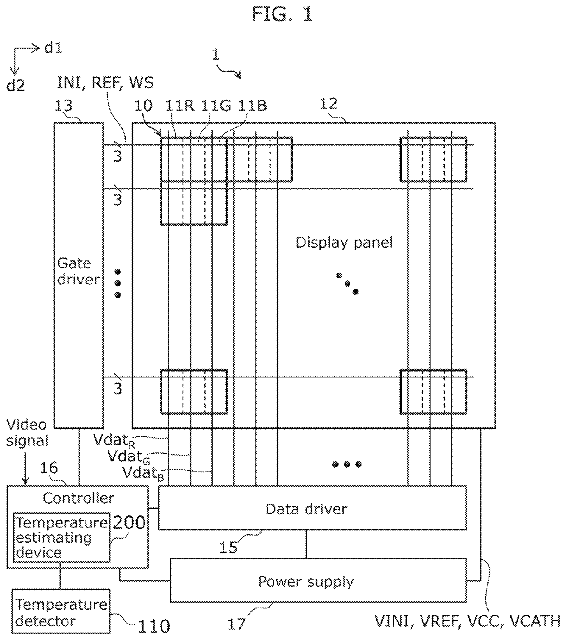
illustrates the basic configuration of display device 1 according to the embodiment. In the following description, for succinctness, the same reference sign will be used to identify a signal and the wiring for transmitting the signal, and the same reference sign will be used to identify a voltage and the wiring for supplying the voltage. Similarly, the same reference sign will be used to identify a circuit and the region where the circuit is formed.
As illustrated in , display device 1 includes display panel 12 , gate driver 13 , data driver 15 , and power supply 17 . Controller 16 includes therein temperature estimating device 200 that estimates the temperature of the surface of display panel 12 . Display device 1 also includes temperature detector 110 that detects the temperature of the substrate. Temperature detector 110 and temperature estimating device 200 will be described later.
Display panel 12 includes a plurality of pixel circuits 10 arranged in a matrix. The plurality of pixel circuits 10 are arranged in first direction d 1 and second direction d 2 intersecting first direction d 1 . First direction d 1 and second direction d 2 are orthogonal to each other.
Each pixel circuit 10 includes three sub-pixel circuits 11 R, 11 G, and 11 B respectively corresponding to the R, G, and B emission colors.
Display panel 12 includes initializing signal line INI, reference signal line REF, and write signal line WS connected to pixel circuits 10 . Initializing signal line INI, reference signal line REF, and write signal line WS respectively transmit to pixel circuits 10 initializing signals INI, reference signals REF, and write signals WS supplied from gate driver 13 .
Display panel 12 also includes data signal lines Vdat R , Vdat G , and Vdat B connected to pixel circuits 10 . Data signal lines Vdat R , Vdat G , and Vdat B respectively transmit to pixel circuits 10 data signals Vdat R , Vdat G , and Vdat B supplied from data driver 15 , which are related to the R, G, and B luminances.
Controller 16 receives an external video signal, and supplies gate driver 13 and data driver 15 with control signals for displaying images corresponding to the frames of the video signal on display panel 12 .
Power supply 17 supplies voltage to display panel 12 , gate driver 13 , data driver 15 , and controller 16 . Display panel 12 is supplied with initializing voltage VINI, reference voltage VREF, positive power supply voltage VCC, and negative power supply voltage VCATH from power supply 17 .
is a circuit diagram of pixel circuit 10 included in display device 1 .
As illustrated in , each sub-pixel circuit 11 R, 11 G, and 11 B includes organic electroluminescent (EL) light-emitting elements EL R , EL G , and EL B , and a plurality of transistors for driving light-emitting elements EL R , EL G , and EL B to emit light. Pixel circuit is supplied with positive power supply voltage VCC, which is voltage for causing light-emitting elements EL R , EL G , and EL B to emit light. Pixel circuit 10 is also supplied, via a cathode layer or the like, with negative power supply voltage VCATH, which is voltage for causing light-emitting elements EL R , EL G , and EL B to emit light.
Each of sub-pixel circuits 11 R, 11 G, and 11 B of pixel circuit 10 has the same configuration. Hereinafter, the configuration of pixel circuit 10 will be described focusing on sub-pixel circuit 11 R.
Sub-pixel circuit 11 R includes initializing transistor T 1 R , voltage compensating transistor T 2 R , write transistor T 3 R , drive transistor TD R , storage capacitor CS R , and light-emitting element EL R .
Initializing transistor T 1 R is placed in an on-state by initializing signal INI, and sets the source node of drive transistor TD R to initializing voltage VINI. Voltage compensating transistor T 2 R is placed in an on-state by reference signal REF, and sets the gate node of drive transistor TD R to reference voltage VREF. Write transistor T 3 R is placed in an on-state by write signal WS, and stores the voltage of data signal Vdat R in storage capacitor CS R . Drive transistor TD R supplies current to light-emitting element EL R in accordance with the voltage stored in storage capacitor CS R . With this, light-emitting element EL R emits light at a luminance in accordance with the voltage of data signal Vdat R .
Sub-pixel circuits 11 G and 11 B have the same configuration as sub-pixel circuit 11 R. Accordingly, in sub-pixel circuits 11 G and 11 B as well, data signals Vdat G and Vdat B are stored at the same time by initializing signal INI, reference signal REF, and write signal WS, and light-emitting elements EL G and EL B emit light at luminances in accordance with the voltages of the stored data signals.
Display device 1 according to the present embodiment includes temperature estimating device 200 that estimates the temperature of the surface of display panel 12 in order to accurately know the deterioration amount of each pixel including light-emitting elements and control the driving of each pixel based on the deterioration amount thereof accordingly.
Temperature Estimating Device Configuration
The configuration of temperature estimating device 200 will be described with reference to through .
is a block diagram of temperature estimating device 200 included in display device 1 . Note that also illustrates temperature detector 110 for detecting the temperature of the substrate.
As illustrated in , temperature estimating device 200 includes substrate temperature obtainer 210 , power obtainer 220 , average power deriver 230 , first influence degree deriver 240 , first increased temperature deriver 250 , and surface temperature estimator 260 . Temperature estimating device 200 also includes storage 270 that stores various information. The functions of each element included in temperature estimating device 200 are realized by hardware included in temperature estimating device 200 . However, the functions of each element included in temperature estimating device 200 may be realized by executing a software program stored in storage 270 .
illustrates one example of display panel 12 included in display device 1 and segmented regions D of display panel 12 .
Display panel 12 includes substrate 12 b . The base material of substrate 12 b is, for example, glass or resin. Pixel circuits 10 described above are provided in display panel 12 . Display panel 12 shows images on panel surface 12 a , which is the surface of display panel 12 .
Temperature detector 110 illustrated in is a sensor that detects the temperature of substrate 12 b , and is provided inside substrate 12 b . However, temperature detector 110 may be provided on the rear surface of substrate 12 b . For example, temperature detector 110 includes a single temperature sensor, but temperature detector 110 is not limited to this example and may include a plurality of temperature sensors. The detection of the temperature of substrate 12 b by temperature detector 110 is performed as required. Temperature information detected by temperature detector 110 is output to substrate temperature obtainer 210 of temperature estimating device 200 .
Substrate temperature obtainer 210 illustrated in obtains the temperature information output from temperature detector 110 . When temperature detector 110 includes a plurality of temperature sensors, substrate temperature obtainer 210 may take the average of the temperatures obtained by the plurality of temperature sensors as the temperature of substrate 12 b . Information related to the temperature of substrate 12 b obtained by substrate temperature obtainer 210 , i.e., information related to substrate temperature Tm, is output to surface temperature estimator 260 that estimates the temperature of the surface of display panel 12 .
In the present embodiment, the temperature of the surface of display panel 12 is estimated based on increased temperature Tr of panel surface 12 a and substrate temperature Tm. Increased temperature Tr of panel surface 12 a is derived based on the brightness of an image displayed on display panel 12 . The brightness of the image is affected by the power supplied to pixel circuit 10 . For example, when the power is high and the image is bright, the temperature of the surface of display panel 12 is high, and when the power is low and the image is dark, the temperature of the surface of display panel 12 is low. Therefore, in the present embodiment, information related to power required to display an image is obtained, and the temperature of display panel 12 is estimated based on this information related to power.
Power obtainer 220 obtains information related to power required to display an image. For example, power obtainer 220 obtains the amount of power used by segmented regions D of display panel 12 based on the image data displayed on display panel 12 .
illustrates one example of segmented regions D of display panel 12 . Segmented regions D are regions in to which display panel 12 has been virtually segmented. The number of segmented regions D is, for example, between 60 and 100, inclusive, and is selected according to, for example, the computing power of temperature estimating device 200 .
When display panel 12 is viewed perpendicular to panel surface 12 a , segmented regions D have a square shape. However, segmented regions D may have a rectangular shape. The aspect ratio of segmented region D may be the same as the aspect ratio of the display region of display panel 12 . Each segmented region D preferably has the same surface area and pixel count. When the surface area of segmented regions D varies, the power of each segmented region D is obtained by converting it into power per unit area, for example.
Power obtainer 220 illustrated in obtains the amount of power used by each of segmented regions D based on the image data displayed on display panel 12 . The power used by a given segmented region D is determined by the current and voltage supplied to the corresponding pixel circuits 10 based on the video signal, which is image data. If the amount of power is obtained per pixel circuit 10 , a huge amount of computing is required in subsequent stages, which is why power obtainer 220 segments display panel 12 into a plurality of blocks and obtains the amount of power per segmented region D. Information related to power obtained by power obtainer 220 is output to average power deriver 230 .
Average power deriver 230 derives average power Pa, which is the average power of all segmented regions D, based on the information related to power output from power obtainer 220 . For example, if heat can diffuse easily and thus the temperature of the entire panel surface 12 a tends to be uniform, increased temperature Tr of panel surface 12 a is dependent on average power Pa of all of segmented regions D. Therefore, average power deriver 230 according to the present embodiment derives average power Pa of all segmented regions D based on the power used in each segmented region D. Note that heat being able to diffuse easily means being able to easily transfer between adjacent segmented regions D owing to a lack of walls partitioning display panel 12 or a hood covering display panel 12 , for example. Information related to average power Pa derived by average power deriver 230 is output to first influence degree deriver 240 .
Based on average power Pa output from average power deriver 230 , first influence degree deriver 240 derives a degree of influence that average power Pa has on a temperature increase of panel surface 12 a . Hereinafter, the degree of influence that average power Pa has on a temperature increase of panel surface 12 a will be referred to as first influence degree i 1 . The function indicating the relationship between average power Pa and first influence degree i 1 will hereinafter be referred to as first power-influence function f 1 .
schematically illustrates first power-influence function f 1 .
For example, first power-influence function f 1 illustrated in can be calculated as follows. First, predetermined image data is shown on a predetermined segmented region D while a thermocouple is contacting the predetermined segmented region D, and the temperature of the predetermined segmented region D is measured. The predetermined image data is data corresponding to a plurality of different shades, and includes, for example three shades—a minimum shade, an intermediate shade, and a maximum shade. For the minimum shade, power is supplied to provide a minimum pixel emission rate, and for the maximum shade, power is supplied to provide a maximum pixel emission rate. For the intermediate shade, power is supplied to provide a pixel emission rate between the maximum and minimum pixel emission rates. The number of different shades is not limited to three; four or more different shades may be used.
Since the environment in which the temperature of display panel 12 is measured with a thermocouple differs from the environment in which display device 1 is actually used, this example normalizes the relationship between the power corresponding to the plurality of different shades and the degree of influence that average power Pa has on a temperature increase of panel surface 12 a . For example, assume the degree of influence of power for producing the minimum shade is a and the degree of influence of power for producing the maximum shade is 1. The degree of influence of power for producing the intermediate shade is set to β which is greater than a and less than 1 (α<β<1) so as to correspond to the temperature measured by the thermocouple. This yields first power-influence function f 1 in which the relationship between average power Pa and first influence degree i 1 is normalized. First power-influence function f 1 may be a function obtained by multivariate analysis. First power-influence function f 1 obtained in this way is stored in storage 270 .
First influence degree deriver 240 illustrated in derives first influence degree i 1 by substituting average power Pa derived by average power deriver 230 into first power-influence function f 1 . First influence degree deriver 240 may derive first influence degree i 1 by data interpolation when there is no influence degree value that directly corresponds to average power Pa. The information related to first influence degree i 1 obtained by first influence degree deriver 240 is output to first increased temperature deriver 250 .
First increased temperature deriver 250 derives the average increased temperature Tr of panel surface 12 a based on the information related to first influence degree i 1 output from first influence degree deriver 240 .
schematically illustrates the relationship between first influence degree i 1 and increased temperature Tr.
First increased temperature deriver 250 multiplies first influence degree i 1 by a predetermined first coefficient g 1 to derive the average increased temperature Tr of panel surface 12 a . For example, the average increased temperature Tr is calculated using the equation “average increased temperature Tr=first coefficient g 1 ×first influence degree i 1 . . . (Expression 1)”.
Coefficient g 1 is a value for applying normalized data to actual data. Coefficient g 1 may be a value that changes depending on the season or region in which display device 1 is used. Coefficient g 1 is set such that the increased temperature is the maximum temperature when first influence degree i 1 is 1. For example, when the maximum increased temperature corresponding to power for producing the maximum shade is 20° C., coefficient g 1 is set to 20 so that first influence degree i 1 equals 1. Coefficient g 1 determined in this manner is stored in storage 270 .
First increased temperature deriver 250 derives the average increased temperature Tr of panel surface 12 a using the predetermined coefficient g 1 . Information related to the average increased temperature Tr of panel surface 12 a is output to surface temperature estimator 260 .
Surface temperature estimator 260 illustrated in estimates the temperature of panel surface 12 a based on substrate temperature Tm obtained by substrate temperature obtainer 210 and the average increased temperature Tr of panel surface 12 a.
illustrates substrate temperature Tm, increased temperature Tr of panel surface 12 a , and estimated temperature Tp of panel surface 12 a.
As illustrated in , surface temperature estimator 260 derives estimated temperature Tp, which is the temperature of panel surface 12 a , by adding the average increased temperature Tr of panel surface 12 a to substrate temperature Tm. Estimated temperature Tp derived by temperature estimating device 200 is processed in controller 16 (see ). Controller 16 knows the deterioration amount of display panel 12 based on estimated temperature Tp, and controls the driving of display panel 12 based on the deterioration amount.
Display device 1 according to the embodiment includes: substrate temperature obtainer 210 that obtains substrate temperature Tm of substrate 12 b of display panel 12 ; power obtainer 220 that obtains an amount of power used by a plurality of segmented regions D of display panel 12 , based on image data displayed on display panel 12 ; first increased temperature deriver 250 that derives increased temperature Tr of panel surface 12 a of display panel 12 based on the amount of power used by the plurality of segmented regions D; and surface temperature estimator 260 that estimates a temperature of panel surface 12 a based on substrate temperature Tm and increased temperature Tr.
According to this display device 1 , increased temperature Tr of panel surface 12 a is derived based on power used by the plurality of segmented regions D of display panel 12 . This makes it possible to appropriately estimate the temperature of panel surface 12 a based on substrate temperature Tm and increased temperature Tr.
Variation 1 of Embodiment
Next, display device 1 according to Variation 1 of the embodiment will be described with reference to and . In the present variation, an example will be given in which average power Pa is gradually changed and output rather than switching average power Pa immediately in accordance with changes in the image data.
Display device 1 according to Variation 1 includes display panel 12 , gate driver 13 , data driver 15 , controller 16 , and power supply 17 . Controller 16 includes therein temperature estimating device 200 A that estimates the temperature of the surface of display panel 12 . Display device 1 according to Variation 1 also includes temperature detector 110 .
is a block diagram of temperature estimating device 200 A included in display device 1 .
As illustrated in , temperature estimating device 200 A includes substrate temperature obtainer 210 , power obtainer 220 , average power deriver 230 A, first influence degree deriver 240 , first increased temperature deriver 250 , and surface temperature estimator 260 . Temperature estimating device 200 A also includes storage 270 that stores various information.
Average power deriver 230 A derives average power Pa of all segmented regions D based on the information related to power output from power obtainer 220 .
For example, when the images shown on display panel 12 correspond to a transition from a dark scene to a bright scene, the amount of power required to show the images is immediately switched, but more often than not the temperature of display panel 12 does not immediately change. In view of this, with average power deriver 230 A according to the present variation, average power Pa is gradually changed and output rather than switching average power Pa immediately in accordance with changes in the image data.
illustrates the average power output from average power deriver 230 A of the temperature estimating device.
In , (a) illustrates average power Pa output from average power deriver 230 according to the embodiment, and (b) illustrates average power Pa output from average power deriver 230 A according to Variation 1.
For example, when the images shown on display panel 12 correspond to a transition from a dark scene to a bright scene, average power Pa abruptly increases as illustrated in (a) in . Since the temperature of display panel 12 does not rise abruptly, when the temperature of panel surface 12 a is estimated based on average power Pa output from average power deriver 230 , the estimated temperature differs from the actual temperature of panel surface 12 a . In view of this, in Variation 1, the temperature of panel surface 12 a is estimated taking into account the delay in the temperature increase of display panel 12 .
As illustrated in (b) in , when a change in average power Pa during predetermined period t 1 is greater than a predetermined threshold, average power Pa is derived so as to change over period t 2 longer than the predetermined period. Specifically, average power deriver 230 A derives a time-varying average power Pa, such that average power Pa changes proportionally over period t 2 . For example, predetermined period t 1 can be selected as appropriate from a range of 0.03 seconds to 0.3 seconds, inclusive. Period t 2 can be selected as appropriate from a range of 10 to 100 times that of predetermined period t 1 , inclusive. For example, when the images correspond to a transition from a dark scene to a bright scene, average power deriver 230 A gradually increases average power Pa, and when the images correspond to a transition from a bright scene to a dark scene, average power deriver 230 A gradually reduces average power Pa.
Average power deriver 230 A outputs average power Pa, which changes over time, to first influence degree deriver 240 . Note that when the frame rate, which is the rate at which the image data updates, influences average power Pa, average power deriver 230 A may derive average power Pa based on the frame rate signal included in the video signal.
First influence degree deriver 240 derives first influence degree i 1 , which changes over time, based on average power Pa, which changes over time, and outputs it to first increased temperature deriver 250 . First increased temperature deriver 250 derives increased temperature Tr of panel surface 12 a , which changes over time, based on first influence degree i 1 , which changes over time, and outputs it to surface temperature estimator 260 . Surface temperature estimator 260 estimates the temperature of panel surface 12 a based on the time-varying increased temperature Tr.
According to display device 1 of Variation 1, it is possible to estimate the temperature of panel surface 12 a in accordance with changes in images shown on display panel 12 .
Variation 2 of Embodiment
Display device 1 according to Variation 2 of the embodiment will be described with reference to and . In the present variation, an example will be given in which the temperature of panel surface 12 a is estimated when the temperature on display panel 12 varies locally.
Display device 1 according to Variation 2 includes display panel 12 , gate driver 13 , data driver 15 , controller 16 , and power supply 17 . Controller 16 includes therein temperature estimating device 200 B that estimates the temperature of the surface of display panel 12 . Display device 1 according to Variation 2 also includes temperature detector 110 .
is a block diagram of temperature estimating device 200 B included in display device 1 .
As illustrated in , temperature estimating device 200 B includes substrate temperature obtainer 210 , power obtainer 220 , average power deriver 230 , first influence degree deriver 240 , first increased temperature deriver 250 , and surface temperature estimator 260 . Temperature estimating device 200 B also includes storage 270 that stores various information. Temperature estimating device 200 B according to Variation 2 further includes second influence degree deriver 280 and second increased temperature deriver 290 .
Substrate temperature obtainer 210 , power obtainer 220 , average power deriver 230 , first influence degree deriver 240 , and first increased temperature deriver 250 are the same as in the embodiment.
In cases in which the temperature on display panel 12 varies locally, temperature estimating device 200 B according to Variation 2 obtains information related to power for selected region D 1 among segmented regions D and information related to power for peripheral regions D 2 among segmented regions D, and estimates the temperature of display panel 12 based on this information related to power. Note that temperature varying locally means heat is not able to easily transfer between adjacent segmented regions D due to the presence of, for example, walls partitioning display panel 12 or a hood covering display panel 12 .
illustrates one example of selected region D 1 and peripheral regions D 2 in display panel 12 .
Selected region D 1 is a predetermined segmented region selected from the plurality of segmented regions D. Selected region D 1 is applied to areas where temperature varies locally. Peripheral regions D 2 are segmented regions D in the surrounding area of selected region D 1 . In the example illustrated in , there is one selected region D 1 and eight peripheral regions D 2 . Selected region D 1 is surrounded by a plurality of peripheral regions D 2 ; selected region D 1 is located at the center of the plurality of peripheral regions D 2 . Selected region D 1 and peripheral regions D 2 have the same quadrangular shape, and each peripheral region D 2 contacts one side or vertex of selected region D 1 . Two adjacent peripheral regions D 2 contact one another at two sides thereof.
Power obtainer 220 illustrated in obtains the amount of power used by each of selected region D 1 and peripheral regions D 2 based on the image data displayed on display panel 12 . The power used by selected region D 1 and peripheral regions D 2 is determined by the current and voltage supplied to the corresponding pixel circuits 10 based on the video signal, which is image data. Information related to power used by selected region D 1 and peripheral regions D 2 obtained by power obtainer 220 is output to second influence degree deriver 280 .
Second influence degree deriver 280 derives the degree of influence that power used by selected region D 1 and power used by peripheral regions D 2 have on a temperature increase of selected region D 1 , based on the power used by selected region D 1 and the power used by peripheral regions D 2 . Hereinafter, the degree of influence that power used by selected region D 1 and power used by peripheral regions D 2 has on a temperature increase of selected region D 1 will be referred to as second influence degree i 2 . The function indicating the relationship between (i) power used by selected region D 1 and power used by peripheral regions D 2 and (ii) second influence degree i 2 will hereinafter be referred to as second power-influence function f 2 .
schematically illustrates second power-influence function f 2 .
For example, second power-influence function f 2 illustrated in can be calculated as follows. First, predetermined image data is shown on selected region D 1 and all peripheral regions D 2 while a thermocouple is contacting selected region D 1 , and the temperature of selected region D 1 is measured. In order to prevent other segmented regions D from influencing selected region D 1 and peripheral regions D 2 , no image is shown on segmented regions D outward of peripheral regions D 2 .
The predetermined image data displayed in selected region D 1 and peripheral regions D 2 is a plurality of types of emission data with different emission regions. In this example, the number and locations of peripheral regions D 2 caused to display the image data are varied. For example, the number of peripheral regions D 2 caused to display the image data is selected from a range of 1 to 8, inclusive. The locations of peripheral regions D 2 caused to display the image data are symmetrical or asymmetrical, every other region, every two regions, every three regions, etc. This yields second power-influence function f 2 in which the relationship between (i) power used by selected region D 1 and power used by peripheral regions D 2 and (ii) second influence degree i 2 is normalized. In this example, since the number of peripheral regions D 2 caused to display the image data is varied, second power-influence function f 2 includes a plurality of functions. Second power-influence function f 2 may be a function obtained by multivariate analysis. Second power-influence function f 2 obtained in this way is stored in storage 270 .
Second influence degree deriver 280 illustrated in derives second influence degree i 2 by substituting the power used by selected region D 1 and the power used by peripheral regions D 2 into second power-influence function f 2 . When a plurality of second power-influence functions f 2 are stored in storage 270 , the second power-influence function f 2 corresponding to the number of peripheral regions D 2 caused to display the image data is selected. Second influence degree deriver 280 may derive second influence degree i 2 by data interpolation when there is no influence degree value that directly corresponds to the power used by selected region D 1 and the power used by peripheral regions D 2 . The information related to second influence degree i 2 obtained by second influence degree deriver 280 is output to second increased temperature deriver 290 .
Second increased temperature deriver 290 derives increased temperature Tr of selected region D 1 based on the information related to second influence degree i 2 output from second influence degree deriver 280 .
schematically illustrates the relationship between second influence degree i 2 and increased temperature Tr of selected region D 1 .
Second increased temperature deriver 290 multiplies second influence degree i 2 by a predetermined second coefficient g 2 to derive increased temperature Tr of selected region D 1 . For example, increased temperature Tr of selected region D 1 is calculated using the equation “increased temperature Tr of selected region D 1 =second coefficient g 2 ×second influence degree i 2 . . . (Expression 2)”.
Coefficient g 2 is a value for applying normalized data to actual data. Coefficient g 2 may be a value that changes depending on the season or region in which display device 1 is used. Coefficient g 2 is set such that the increased temperature is the maximum temperature when second influence degree i 2 is 1. For example, when the maximum increased temperature is 20° C. at 100% emission rate of the pixels corresponding to selected region D 1 and all peripheral regions D 2 , coefficient g 2 is set to 20 so that second influence degree i 2 equals 1. Coefficient g 2 determined in this manner is stored in storage 270 . Second increased temperature deriver 290 derives increased temperature Tr of selected region D 1 using the predetermined coefficient g 2 .
Although the above describes an example in which there is one selected region D 1 , two or more selected regions D 1 may be used according to the size of the region characterized by a locally different temperature. Here, an example will be given in which a plurality of selected regions D 1 are contiguous along the surface of display panel 12 .
Second increased temperature deriver 290 derives an increased temperature for selected regions D 1 by interpolation between pixels included in selected regions D 1 based on increased temperatures Tr derived per selected region D 1 .
illustrates one example of increased temperature Tr for selected regions D 1 and increased temperature Tr for pixels.
In , (a) illustrates a plan view of nine selected regions D 1 , and (b) illustrates increased temperature Tr for three selected regions D 1 that are contiguous in first direction d 1 in (a). In , increased temperature Tr for the three selected regions D 1 abruptly increases and decreases from one selected region D 1 to another. In , (c) illustrates an example in which increased temperature Tr for the three selected regions D 1 is expressed as increased temperature Tr for the pixels. In , increased temperature Tr for the three selected regions D 1 gradually increases and decreases from one selected region D 1 to another.
Second increased temperature deriver 290 converts increased temperature Tr for the three selected regions D 1 illustrated in (b) in into increased temperature Tr for the pixels by interpolation between the pixels included in the three selected regions D 1 . This conversion smoothens the changes in increased temperature Tr for selected regions D 1 , as illustrated (c) in . Information related to the converted increased temperature Tr for selected regions D 1 is output to surface temperature estimator 260 .
Surface temperature estimator 260 illustrated in estimates the temperature of panel surface 12 a based on substrate temperature Tm obtained by substrate temperature obtainer 210 , the average increased temperature Tr of panel surface 12 a , and increased temperature Tr for selected regions D 1 .
illustrates substrate temperature Tm, increased temperature Tr of panel surface 12 a , increased temperature Tr for selected regions D 1 , and estimated temperature Tp of panel surface 12 a.
As illustrated in , surface temperature estimator 260 derives estimated temperature Tp, which is the temperature of panel surface 12 a , by adding the average increased temperature Tr of panel surface 12 a and increased temperature Tr for selected regions D 1 to substrate temperature Tm. Since increased temperature Tr of selected regions D 1 is a gradual temperature distribution obtained by interpolation between pixels, estimated temperature Tp is also a gradual temperature distribution similar to the actual temperature of panel surface 12 a . Estimated temperature Tp derived by temperature estimating device 200 B is processed in controller 16 (see ). Controller 16 knows the deterioration amount of display panel 12 based on estimated temperature Tp, and controls the driving of display panel 12 based on the deterioration amount.
With display device 1 according to Variation 2, the temperature of panel surface 12 a is estimated by adding increased temperature Tr for selected regions D 1 to substrate temperature Tm and the average increased temperature Tr of panel surface 12 a . This makes it possible to appropriately estimate the temperature of the surface of display panel 12 in cases in which the temperature on display panel 12 varies locally.
Variation 3 of Embodiment
Display device 1 according to Variation 3 of the embodiment will be described with reference to . In the present variation, an example will be given in which the temperature of panel surface 12 a is estimated when heat is very unlikely to diffuse on display panel 12 . In this variation, the temperature of panel surface 12 a is estimated using increased temperature Tr of selected region D 1 , without using the average increased temperature Tr of panel surface 12 a described in the embodiment.
Display device 1 according to Variation 3 includes display panel 12 , gate driver 13 , data driver 15 , controller 16 , and power supply 17 . Controller 16 includes therein temperature estimating device 200 C that estimates the temperature of the surface of display panel 12 . Display device 1 according to Variation 3 also includes temperature detector 110 .
is a block diagram of temperature estimating device 200 C included in display device 1 .
As illustrated in , temperature estimating device 200 C includes substrate temperature obtainer 210 , power obtainer 220 , second influence degree deriver 280 , second increased temperature deriver 290 , and surface temperature estimator 260 . Temperature estimating device 200 B also includes storage 270 that stores various information.
Substrate temperature obtainer 210 , power obtainer 220 , second influence degree deriver 280 , and second increased temperature deriver 290 are the same as in Variation 2.
In cases in which the temperature on display panel 12 varies locally, temperature estimating device 200 C according to Variation 3 also obtains information related to power for selected region D 1 among segmented regions D and information related to power for peripheral regions D 2 among segmented regions D, and estimates the temperature of display panel 12 based on this information related to power.
Power obtainer 220 obtains the amount of power used by each of selected region D 1 and peripheral regions D 2 based on the image data displayed on display panel 12 .
Second influence degree deriver 280 derives the degree of influence (second influence degree i 2 ) that power used by selected region D 1 and power used by peripheral regions D 2 have on a temperature increase of selected region D 1 , based on the power used by selected region D 1 and the power used by peripheral regions D 2 .
Second increased temperature deriver 290 multiplies second influence degree i 2 by a predetermined second coefficient g 2 to derive increased temperature Tr of selected region D 1 . Second increased temperature deriver 290 derives the increased temperature for selected regions D 1 by interpolation between pixels included in selected regions D 1 based on increased temperatures Tr derived per selected region D 1 .
Surface temperature estimator 260 estimates the temperature of panel surface 12 a based on substrate temperature Tm obtained by substrate temperature obtainer 210 and increased temperature Tr of selected region D 1 .
With display device 1 according to Variation 3, the temperature of panel surface 12 a is estimated by adding increased temperature Tr of selected region D 1 to substrate temperature Tm. This makes it possible to appropriately estimate the temperature of the surface of display panel 12 in cases in which the temperature on display panel 12 varies locally.
CONCLUSION
Display device 1 according to the present embodiment includes: substrate temperature obtainer 210 that obtains substrate temperature Tm of substrate 12 b of display panel 12 ; power obtainer 220 that obtains an amount of power used by a plurality of segmented regions D of display panel 12 , based on image data displayed on display panel 12 ; increased temperature deriver 250 (or 290 ) that derives increased temperature Tr of panel surface 12 a of display panel 12 based on the amount of power used by the plurality of segmented regions D; and surface temperature estimator 260 that estimates a temperature of panel surface 12 a based on substrate temperature Tm and increased temperature Tr.
According to this display device 1 , increased temperature Tr of panel surface 12 a is derived based on power used by the plurality of segmented regions D of display panel 12 . This makes it possible to appropriately estimate the temperature of the surface of display panel 12 based on substrate temperature Tm and increased temperature Tr.
Display device 1 may further include: average power deriver 230 that derives average power Pa used by all of the plurality of segmented regions D based on an amount of power used by each of the plurality of segmented regions D; and first influence degree deriver 240 that derives, based on average power Pa, first influence degree i 1 indicating a degree of influence that average power Pa has on a temperature increase of panel surface 12 a . The increased temperature deriver is first increased temperature deriver 250 that derives an average increased temperature Tr of panel surface 12 a based on first influence degree i 1 . Surface temperature estimator 260 may estimate the temperature of panel surface 12 a by summing substrate temperature Tm and the average increased temperature Tr of panel surface 12 a.
In this way, it is possible to appropriately derive the average increased temperature Tr of panel surface 12 a by deriving first influence degree i 1 based on average power Pa and deriving the average increased temperature Tr based on first influence degree i 1 . This makes it possible to appropriately estimate the temperature of the surface of display panel 12 based on substrate temperature Tm and the average increased temperature Tr.
Display device 1 may further include: storage 270 that stores first power-influence function f 1 indicating a relationship between average power Pa and first influence degree i 1 . First influence degree deriver 240 may derive first influence degree i 1 by substituting average power Pa derived by average power deriver 230 into first power-influence function f 1 .
In this way, it is possible to appropriately derive first influence degree i 1 by substituting average power Pa derived by average power deriver 230 into first power-influence function f 1 . This makes it possible to appropriately derive the average increased temperature Tr of panel surface 12 a based on first influence degree i 1 , and appropriately estimate the temperature of the surface of display panel 12 .
First increased temperature deriver 250 may derive the average increased temperature Tr of panel surface 12 a by multiplying first influence degree i 1 by a predetermined first coefficient g 1 .
In this way, it is possible to appropriately derive the average increased temperature Tr of panel surface 12 a by multiplying first influence degree i 1 by first coefficient g 1 . This makes it possible to appropriately estimate the temperature of the surface of display panel 12 .
When a change in average power Pa during predetermined period t 1 is greater than a predetermined threshold, average power deriver 230 may derive average power Pa so as to change over period t 2 longer than predetermined period t 1 .
With this, it is possible to derive first influence degree i 1 , which changes over time, based on average power Pa, which changes over time. Accordingly, even in cases in which, for example, the image shown on display panel 12 abruptly changes, the average increased temperature Tr of panel surface 12 a can be appropriately derived based on first influence degree i 1 , which changes over time. This makes it possible to appropriately estimate the temperature of the surface of display panel 12 based on substrate temperature Tm and the average increased temperature Tr.
Surface temperature estimator 260 may estimate the temperature of the entirety of panel surface 12 a.
This makes it possible to appropriately estimate the temperature of the entire surface of display panel 12 .
Display device 1 may further include: second influence degree deriver 280 that derives second influence degree i 2 indicating a degree of influence that power used by selected region D 1 and power used by peripheral regions D 2 have on a temperature increase of selected region D 1 , based on the power used by selected region D 1 and the power used by peripheral regions D 2 , selected region D 1 being a predetermined segmented region selected from the plurality of segmented regions D, peripheral regions D 2 being segmented regions, among the plurality of segmented regions D, in a surrounding area of selected region D 1 ; and second increased temperature deriver 290 that derives increased temperature Tr of selected region D 1 based on second influence degree i 2 . Surface temperature estimator 260 may estimate the temperature of panel surface 12 a by summing substrate temperature Tm, the average increased temperature Tr of panel surface 12 a , and increased temperature Tr of selected region D 1 .
In this way, it is possible to appropriate derive increased temperature Tr of selected region D 1 by deriving second influence degree i 2 based on the power used by selected region D 1 and the power used by peripheral regions D 2 , and deriving increased temperature Tr of selected region D 1 based on second influence degree i 2 . This makes it possible to appropriately estimate the temperature of the surface of display panel 12 based on substrate temperature Tm, the average increased temperature Tr of panel surface 12 a , and increased temperature Tr of selected region D 1 .
Display device 1 may further include storage 270 that stores second power-influence function f 2 indicating a relationship between (i) the power used by selected region D 1 and the power used by peripheral regions D 2 and (ii) second influence degree i 2 . Second influence degree deriver 280 may derive second influence degree i 2 by substituting the power used by selected region D 1 and the power used by peripheral regions D 2 into second power-influence function f 2 .
This makes it possible to appropriately derive second influence degree i 2 by substituting the power used by selected region D 1 and the power used by peripheral regions D 2 into second power-influence function f 2 . This makes it possible to appropriately derive increased temperature Tr of selected region D 1 based on second influence degree i 2 , and appropriately estimate the temperature of the surface of display panel 12 .
Second increased temperature deriver 290 may derive increased temperature Tr of selected region D 1 by multiplying second influence degree i 2 by a predetermined second coefficient g 2 .
In this way, it is possible to appropriately derive increased temperature Tr of selected region D 1 by multiplying second influence degree i 2 by second coefficient g 2 . This makes it possible to appropriately estimate the temperature of the surface of display panel 12 .
Second increased temperature deriver 290 may derive increased temperature Tr for selected regions D 1 by interpolation between pixels included in selected regions D 1 based on increased temperatures Tr derived per selected region D 1 .
In this way, it is possible to inhibit abrupt changes in increased temperature Tr from one selected region D 1 to another by interpolation between pixels included in selected regions D 1 based on increased temperature Tr for selected regions D 1 . This makes it possible to appropriately derive increased temperature Tr of selected regions D 1 , and appropriately estimate the temperature of the surface of display panel 12 .
Surface temperature estimator 260 may estimate a local temperature of panel surface 12 a.
This makes it possible to appropriately estimate the temperature of the surface of display panel 12 .
Display device 1 may further include: influence degree deriver 280 that derives influence degree i 2 that power used by selected region D 1 and power used by peripheral regions D 2 have on a temperature increase of selected region D 1 , based on the power used by selected region D 1 and the power used by peripheral regions D 2 , selected region D 1 being a predetermined segmented region selected from the plurality of segmented regions D, peripheral regions D 2 being segmented regions, among the plurality of segmented regions D, in a surrounding area of selected region D 1 . Increased temperature deriver 290 may derive increased temperature Tr of selected region D 1 based on degree of influence i 2 . Surface temperature estimator 260 may estimate the temperature of panel surface 12 a by adding increased temperature Tr of selected region D 1 to substrate temperature Tm.
In this way, it is possible to appropriate derive increased temperature Tr of selected region D 1 by deriving the above-described influence degree i 2 based on the power used by selected region D 1 and the power used by peripheral regions D 2 , and deriving increased temperature Tr of selected region D 1 based on influence degree i 2 . This makes it possible to appropriately estimate the temperature of the surface of display panel 12 based on substrate temperature Tm and increased temperature Tr of selected region D 1 .
Other Embodiments
Note that the present disclosure is not limited to the configurations described in the above embodiment and variations thereof; modifications may be made as appropriate.
Although substrate temperature Tm described in the embodiment is exemplified as a temperature detected by a temperature sensor, substrate temperature Tm is not limited to this example. For example, the temperature detected by the temperature sensor may be corrected according to a heat characteristic of display device 1 , and the corrected temperature may be used as substrate temperature Tm. Examples of correction according to a heat characteristic of display device 1 include correction according to heat generated by the power supply IC in substrate 12 b and correction according to the temperature inside the housing of display device 1 .
In Variation 2, an example is given in which increased temperature Tr of selected region D 1 is further added to the average increased temperature Tr, but either first coefficient g 1 or second coefficient g 2 may be modified to avoid adding two increased temperatures to the same segmented region D on display panel 12 . For example, in Variation 2, first coefficient g 1 used by first increased temperature deriver 250 may be changed to a smaller value than first coefficient g 1 used in the embodiment.
In Variation 2, an example is given in which interpolation between pixels included in three selected regions D 1 is performed based on increased temperature Tr for the three selected regions D 1 , but this interpolation process does not necessarily need to be performed. For example, when the surface area of selected region D 1 is sufficiently small, increased temperature Tr of selected region D 1 can be used as-is without performing the pixel interpolation process to estimate the temperature of the surface of display panel 12 .
For example, the light-emitting element is not limited to an organic EL element, and may be some other light-emitting element such as an LED.
For example, gate driver 13 may be arranged at one short side of display panel 12 as illustrated in , but is not limited to this example, and may be arranged at the two opposing short sides of display panel 12 . Moreover, data driver 15 may be arranged at one long side of display panel 12 as illustrated in , but is not limited to this example, and may be arranged at the two opposing long sides of display panel 12 .
Various modifications to the embodiments as well as embodiments resulting from arbitrary combinations of elements and functions of different embodiments that may be conceived by those skilled in the art are included in the scope of in the present disclosure as long as they do not depart from the novel teachings of the present disclosure. For example, examples of the display device including the temperature estimating device according to the present disclosure that are included in the scope of the present disclosure include flat screen television systems, gaming devices that include a display panel, and PC monitor systems.
INDUSTRIAL APPLICABILITY
The present disclosure is widely applicable as a display device in a variety of video display devices such as mobile information terminals, personal computers, television receivers, etc.
Figures (11)
Citations
This patent cites (14)
- US10629118
- US11837161
- US20120033151
- US20140104259
- US20170140719
- US20170236490
- US20200335874
- US20200372861
- US20210201758
- US20210398485
- US20220108650
- US20220130332
- US20230186826
- US20230410714