Abstract
A wide-angle lens assembly includes a first lens, a second lens, a third lens, a fourth lens, and a fifth lens. The first lens is a meniscus lens with refractive power and includes a convex surface facing an object side and a concave surface facing an image side. The second lens is with refractive power. The third lens is with positive refractive power. The fourth lens is with refractive power. The fifth lens is with positive refractive power and includes a convex surface facing the image side. The first lens, the second lens, the third lens, the fourth lens, and the fifth lens are arranged in order from the object side to the image side along an optical axis.
Claims (20)
1. A wide-angle lens assembly comprising: a seventh lens which is with refractive power and comprises a convex surface facing an object side; a first lens which is a meniscus lens with refractive power and comprises a convex surface facing the object side and a concave surface facing an image side; a sixth lens which is with refractive power; a second lens which is with positive refractive power; a stop; a third lens which is with positive refractive power and comprises a convex surface facing the object side; an eighth lens which is with positive refractive power; a fourth lens which is with refractive power and comprises a concave surface facing the object side; and a fifth lens which is a biconvex lens with positive refractive power and comprises a convex surface facing the object side and another convex surface facing the image side; wherein the sixth lens and the seventh lens have opposite refractive power; wherein the seventh lens, the first lens, the sixth lens, the second lens, the third lens, the eighth lens, the fourth lens, and the fifth lens are arranged from the object side to the image side along an optical axis; wherein the stop is disposed between the second lens and the eighth lens; wherein the relative positions of the lenses are fixed; wherein the wide-angle lens assembly satisfies the following condition: 5.5< TTL/f< 10; wherein TTL is an interval from an object side surface of the lens closest to the object side to an image plane along the optical axis and f is an effective focal length of the wide-angle lens assembly.
10. A wide-angle lens assembly comprising: a seventh lens which is with refractive power and comprises a convex surface facing an object side; a first lens which is a meniscus lens with refractive power and comprises a convex surface facing the object side and a concave surface facing an image side; a sixth lens which is with refractive power; a second lens which is with positive refractive power; a third lens which is with positive refractive power and comprises a convex surface facing the object side; an eighth lens which is with positive refractive power; a fourth lens which is with refractive power and comprises a concave surface facing the object side; a fifth lens which is a biconvex lens with positive refractive power and comprises a convex surface facing the object side and another convex surface facing the image side; and a ninth lens which is with negative refractive power and comprises a concave surface facing the object side; wherein the sixth lens and the seventh lens have opposite refractive power; wherein the wide-angle lens assembly satisfies the following condition: 5.5< TTL/f< 10; wherein TTL is an interval from an object side surface of the lens closest to the object side to an image plane along the optical axis and f is an effective focal length of the wide-angle lens assembly; wherein the seventh lens, the first lens, the sixth lens, the second lens, the third lens, the eighth lens, the fourth lens, the fifth lens, and the ninth lens are arranged from the object side to the image side along the optical axis; wherein the relative positions of the lenses are fixed.
Show 18 dependent claims
2. The wide-angle lens assembly as claimed in claim 1 , wherein the eighth lens is cemented with the fourth lens.
3. The wide-angle lens assembly as claimed in claim 1 , further comprising a ninth lens disposed between the fifth lens and the image side, the ninth lens is with negative refractive power and comprises a concave surface facing the object side.
4. The wide-angle lens assembly as claimed in claim 3 , wherein the fifth lens is cemented with the ninth lens.
5. The wide-angle lens assembly as claimed in claim 1 , further comprising a tenth lens disposed between the fourth lens and the image side, the tenth lens is with positive refractive power and comprises a convex surface facing the object side and another convex surface facing the image side.
6. The wide-angle lens assembly as claimed in claim 1 , wherein the second lens comprises a convex surface facing the image side, the sixth lens is with negative refractive power and comprises a concave surface facing the image side, and the seventh lens is with positive refractive power.
7. The wide-angle lens assembly as claimed in claim 1 , wherein: the seventh lens is with negative refractive power; the sixth lens is with positive refractive power; the sixth lens comprises a concave surface facing the object side; the sixth lens comprises a convex surface facing the image side, or the third lens comprises a convex surface facing the image side, or both the sixth lens and the third lens comprise a convex surface facing the image side; and the second lens comprises a convex surface facing the object side and a concave surface facing the image side.
8. The wide-angle lens assembly as claimed in claim 1 , wherein the seventh lens further comprises a concave surface facing the image side, the first lens is with negative refractive power, or the fourth lens is with negative refractive power, or both the first lens and the fourth lens are with negative refractive power, and the eighth lens comprises a convex surface facing the object side and another convex surface facing the image side.
9. The wide-angle lens assembly as claimed in claim 1 , wherein the wide-angle lens assembly satisfies at least one of the following conditions: 1.3< TTL/R 71 <2.6; 0.03<| f 71 /f 62 |<1.7; 30< Vd 7 <64.3; 35< Vd 1 <54.5; wherein TTL is the interval from the object side surface of the lens closest to the object side to the image plane along the optical axis, R 71 is a radius of curvature of the object side surface of the seventh lens, f 71 is an effective focal length of a combination of the seventh lens and the first lens, f 62 is an effective focal length of a combination of the sixth lens and the second lens, Vd 7 is an Abbe number of the seventh lens, and Vd 1 is an Abbe number of the first lens.
11. The wide-angle lens assembly as claimed in claim 1 , wherein the first lens is with negative refractive power, the second lens comprises a convex surface facing the object side, and the third lens comprises a convex surface facing the image side.
12. The wide-angle lens assembly as claimed in claim 11 , wherein the wide-angle lens assembly satisfies at least one of the following condition: 0.4≤ BFL/TTL≤ 0.5; 1.1≤ BFL/TTL≤ 2.8; 4≤ TTL /IH≤6.5; 0.8≤| f 1 |/f≤ 1.5; −0.93< f 1 /f 5 ≤−0.68; wherein BFL is an interval from an image side surface of the fifth lens to an image plane along the optical axis, TTL is an interval from an object side surface of the first lens to the image plane along the optical axis, IH is a half image height of the image plane of the wide-angle lens assembly, f is an effective focal length of the wide-angle lens assembly, f 1 is the effective focal length of the first lens, and f 5 is an effective focal length of the fifth lens.
13. The wide-angle lens assembly as claimed in claim 11 , wherein the sixth lens is with negative refractive power and comprises a concave surface facing the object side and another concave surface facing the image side.
14. The wide-angle lens assembly as claimed in claim 11 , wherein the second lens further comprises another convex surface facing the image side, and the fourth lens is with negative refractive power and comprises a concave surface facing the object side and another concave surface facing the image side.
15. The wide-angle lens assembly as claimed in claim 11 , further comprising a stop disposed between the second lens and the third lens.
16. The wide-angle lens assembly as claimed in claim 10 , further comprising a stop disposed between the second lens and the eighth lens.
17. The wide-angle lens assembly as claimed in claim 10 , wherein the eighth lens is cemented with the fourth lens.
18. The wide-angle lens assembly as claimed in claim 10 , wherein the fifth lens is cemented with the ninth lens.
19. The wide-angle lens assembly as claimed in claim 10 , wherein the seventh lens further comprises a concave surface facing the image side, the first lens is with negative refractive power, or the fourth lens is with negative refractive power, or both the first lens and the fourth lens are with negative refractive power, and the eighth lens comprises a convex surface facing the object side and another convex surface facing the image side.
20. The wide-angle lens assembly as claimed in claim 10 , wherein the wide-angle lens assembly satisfies at least one of the following conditions: 1.3< TTL/R 71 <2.6; 0.03<| f 71 /f 62 |<1.7; 30< Vd 7 <64.3; 35< Vd 1 <54.5; wherein TTL is the interval from the object side surface of the lens closest to the object side to the image plane along the optical axis, R 71 is a radius of curvature of the object side surface of the seventh lens, f 71 is an effective focal length of a combination of the seventh lens and the first lens, f 62 is an effective focal length of a combination of the sixth lens and the second lens, Vd 7 is an Abbe number of the seventh lens, and Vd 1 is an Abbe number of the first lens.
Full Description
Show full text →
BACKGROUND OF THE INVENTION
Field of the Invention
The invention relates to a wide-angle lens assembly.
Description of the Related Art
The current development trend of a wide-angle lens assembly is toward miniaturization and small F-number. Additionally, the wide-angle lens assembly is developed to have high resolution and resistance to environmental temperature change in accordance with different application requirements. However, the known wide-angle lens assembly can't satisfy such requirements. Therefore, the wide-angle lens assembly needs a new structure in order to meet the requirements of miniaturization, small F-number, high resolution, and resistance to environmental temperature change at the same time.
BRIEF SUMMARY OF THE INVENTION
The invention provides a wide-angle lens assembly to solve the above problems. The wide-angle lens assembly of the invention is provided with characteristics of a decreased total lens length, a decreased F-number, an increased resolution, a resisted environmental temperature change, and still has a good optical performance.
The wide-angle lens assembly in accordance with an exemplary embodiment of the invention includes a first lens, a second lens, a third lens, a fourth lens, and a fifth lens. The first lens is a meniscus lens with refractive power and includes a convex surface facing an object side and a concave surface facing an image side. The second lens is with refractive power. The third lens is with positive refractive power. The fourth lens is with refractive power. The fifth lens is a biconvex lens with positive refractive power and includes a convex surface facing the object side and another convex surface facing the image side. The first lens, the second lens, the third lens, the fourth lens, and the fifth lens are arranged in order from the object side to the image side along an optical axis.
In another exemplary embodiment, the wide-angle lens assembly further includes a sixth lens disposed between the first lens and the second lens, a seventh lens disposed between the object side and the first lens; an eighth lens disposed between the third lens and the fourth lens; and a stop disposed between the second lens and the eighth lens; wherein the second lens is with positive refractive power; wherein the third lens includes a convex surface facing the object side; wherein the fourth lens includes a concave surface facing the object side; wherein the sixth lens is with refractive power; wherein the seventh lens is with refractive power and includes a convex surface facing the object side; wherein the eighth lens is with positive refractive power; wherein the seventh lens, the first lens, the sixth lens, the second lens, the third lens, the eighth lens, the fourth lens, and the fifth lens are arranged in order from the object side to the image side along an optical axis; wherein the relative positions of the lenses are fixed; wherein the wide-angle lens assembly satisfies the following condition: 5.5<TTL/f<10; wherein TTL is an interval from an object side surface of the seventh lens to an image plane along the optical axis and f is an effective focal length of the wide-angle lens assembly.
In yet another exemplary embodiment, the eighth lens is cemented with the fourth lens.
In another exemplary embodiment, the wide-angle lens assembly further includes a ninth lens disposed between the fourth lens and the image side.
In yet another exemplary embodiment, the fifth lens is cemented with the ninth lens.
In another exemplary embodiment, the ninth lens is with negative refractive power and includes a concave surface facing the object side.
In yet another exemplary embodiment, the wide-angle lens assembly further includes a tenth lens disposed between the fourth lens and the image side.
In another exemplary embodiment, the tenth lens is with positive refractive power and includes a convex surface facing the object side and another convex surface facing the image side.
In yet another exemplary embodiment, the second lens includes a convex surface facing the image side; the sixth lens is with negative refractive power and includes a concave surface facing the image side; the seventh lens is with positive refractive power.
In another exemplary embodiment, the seventh lens is with negative refractive power; the sixth lens is with positive refractive power; the sixth lens includes a concave surface facing the object side, or the fifth lens includes a concave surface facing the object side, or both the sixth lens and the fifth lens includes a concave surface facing the object side; the sixth lens includes a convex surface facing the image side, or the third lens includes a convex surface facing the image side, or both the sixth lens and the third lens includes a convex surface facing the image side; the second lens comprises a convex surface facing the object side and a concave surface facing the image side.
In yet another exemplary embodiment, the seventh lens further includes a concave surface facing the image side; the first lens is with negative refractive power, or the fourth lens is with negative refractive power, or both the first lens and the fourth lens are with negative refractive power; the third lens is with positive refractive power, or the fifth lens is with positive refractive power, or both the third lens and the fifth lens are with positive refractive power; the eighth lens includes a convex surface facing the object side and another convex surface facing the image side.
In another exemplary embodiment, the wide-angle lens assembly satisfies at least one of the following conditions: 1.3<TTL/R 71 <2.6; 0.03<| f 71 /f 62 |<1.7; 30<Vd 7 <64.3; 35<Vd 1 <54.5; wherein TTL is the interval from the object side surface of the seventh lens to the image plane along the optical axis, R 71 is a radius of curvature of the object side surface of the seventh lens, f 71 is an effective focal length of a combination of the seventh lens and the first lens, f 62 is an effective focal length of a combination of the sixth lens and the second lens, Vd 7 is an Abbe number of the seventh lens, and Vd 1 is an Abbe number of the first lens.
In yet another exemplary embodiment, the wide-angle lens assembly further includes a sixth lens disposed between the first lens and the second lens; a seventh lens disposed between the object side and the first lens; an eighth lens disposed between the third lens and the fourth lens; a ninth lens disposed between the fourth lens and the image side; wherein the second lens is with positive refractive power; wherein the third lens includes a convex surface facing the object side; wherein the fourth lens includes a concave surface facing the object side; wherein the sixth lens is with refractive power; wherein the seventh lens is with refractive power and includes a convex surface facing the object side; wherein the eighth lens is with positive refractive power; wherein the ninth lens is with negative refractive power and includes a concave surface facing the object side; wherein the seventh lens, the first lens, the sixth lens, the second lens, the third lens, the eighth lens, the fourth lens, the fifth lens, and the ninth lens are arranged in order from the object side to the image side along an optical axis; wherein the relative positions of the lenses are fixed.
In another exemplary embodiment, the first lens is with negative refractive power: the second lens includes a convex surface facing the object side; the third lens includes a convex surface facing the image side; the wide-angle lens assembly satisfies the following condition: 0.8≤|f 1 |/f≤1.5; wherein f 1 is an effective focal length of the first lens and f is an effective focal length of the wide-angle lens assembly.
In yet another exemplary embodiment, the wide-angle lens assembly satisfies the following condition: 0.4≤BFL/TTL≤0.5; wherein BFL is an interval from an image side surface of the fifth lens to an image plane along the optical axis and TTL is an interval from an object side surface of the first lens to the image plane along the optical axis.
In another exemplary embodiment, the wide-angle lens assembly further includes a sixth lens disposed between the first lens and the second lens, wherein the sixth lens is with negative refractive power and includes a concave surface facing the object side and another concave surface facing the image side.
In yet another exemplary embodiment, the first lens further includes a convex surface facing the object side; the second lens is with positive refractive power and further includes another convex surface facing the image side; the third lens is with positive refractive power and further includes another convex surface facing the object side; the fourth lens is with negative refractive power and includes a concave surface facing the object side and another concave surface facing the image side; the fifth lens further includes another convex surface facing the object side.
In another exemplary embodiment, the wide-angle lens assembly satisfies at least one of the following conditions: 1.1≤BFL/IH<2.8; 4≤TTL/IH≤6.5; −0.93≤f 1 /f 5 ≤−0.68; wherein BFL is an interval from an image side surface of the fifth lens to an image plane along the optical axis, IH is a half image height of the image plane of the wide-angle lens assembly, TTL is an interval from an object side surface of the first lens to the image plane along the optical axis, f 1 is the effective focal length of the first lens, and f 5 is an effective focal length of the fifth lens.
In yet another exemplary embodiment, the wide-angle lens assembly further includes a stop disposed between the second lens and the third lens.
In another exemplary embodiment, the first lens, the second lens, the third lens, the fourth lens, the fifth lens, and the sixth lens are aspheric plastic lenses.
In yet another exemplary embodiment, the wide-angle lens assembly further includes a reflective element disposed between the fifth lens and the image side.
In another exemplary embodiment, the wide-angle lens assembly further includes a sixth lens disposed between the first lens and the second lens, wherein the sixth lens is with negative refractive power and includes a convex surface facing the object side; the second lens includes a convex surface facing the image side; the wide-angle lens assembly satisfies the following condition: −8.3<f 162 /f≤14; wherein f 162 is an effective focal length of a combination of the first lens, the sixth lens, and the second lens, and f is an effective focal length of the wide-angle lens assembly.
In yet another exemplary embodiment, the wide-angle lens assembly further includes a sixth lens disposed between the first lens and the second lens, wherein the sixth lens is with negative refractive power and includes a convex surface facing the object side; the second lens includes a convex surface facing the image side; the wide-angle lens assembly satisfies the following condition: 4 mm≤f+f 3 ≤5 mm; wherein f is an effective focal length of the wide-angle lens assembly and f 3 is an effective focal length of the third lens.
In another exemplary embodiment, the wide-angle lens assembly satisfies the following condition: −5.65 mm≤(R 21 ×R 22 )/(R 21 +R 22 )≤−3.8 mm: wherein R 21 is a radius of curvature of an object side surface of the second lens and R 22 is a radius of curvature of an image side surface of the second lens.
In yet another exemplary embodiment, the wide-angle lens assembly satisfies the following condition: 0.5<|(CRA−MRA)/CRA|<1.02; wherein CRA is a chief ray angle of a maximum image height of the wide-angle lens assembly and MRA is a marginal ray angle of the maximum image height of the wide-angle lens assembly.
In another exemplary embodiment, the first lens is with negative refractive power; the sixth lens further includes a concave surface facing the image side; the second lens is with negative refractive power and further includes a convex surface or a concave surface facing the object side; the third lens includes a convex surface facing the object side and another convex surface facing the image side; the fourth lens is with negative refractive power and includes a concave surface facing the object side and another concave surface facing the image side.
In yet another exemplary embodiment, the wide-angle lens assembly satisfies at least one of the following conditions: −45 degrees/mm≤FOV/f 1 ≤−22 degrees/mm; 105≤Vd 1 +Vd 3 <140; wherein FOV is a field of view of the wide-angle lens assembly, f 1 is an effective focal length of the first lens, Vd 1 is an Abbe number of the first lens, and Vd 3 is an Abbe number of the third lens.
In another exemplary embodiment, the wide-angle lens assembly satisfies the following condition: −5.1≤(f 6 +f 4 )/f<−3.6, wherein f is the effective focal length of the wide-angle lens assembly, f 6 is an effective focal length of the sixth lens, and f 4 is an effective focal length of the fourth lens.
In yet another exemplary embodiment, the wide-angle lens assembly satisfies at least one of the following conditions: 0.12≤BFL/TTL≤0.23; 9≤TTL/T 3 ≤19; wherein BFL is an interval from an image side surface of a lens which is closest to the image side to an image plane along the optical axis, TTL is an interval from an object side surface of the first lens to the image plane along the optical axis, and T 3 is a thickness of the third lens along the optical axis.
In another exemplary embodiment, the wide-angle lens assembly further includes a seventh lens disposed between the fifth lens and the image side, wherein the seventh lens is with positive refractive power and includes a concave surface facing the object side and a convex surface facing the image side.
In yet another exemplary embodiment, the wide-angle lens assembly further includes a seventh lens disposed between the fifth lens and the image side, wherein the seventh lens is with negative refractive power and includes a concave surface facing the object side and another concave surface facing the image side.
A detailed description is given in the following embodiments with reference to the accompanying drawings.
BRIEF DESCRIPTION OF THE DRAWINGS
The invention can be more fully understood by reading the subsequent detailed description and examples with references made to the accompanying drawings, wherein:
is a lens layout diagram of a wide-angle lens assembly in accordance with a first embodiment of the invention;
A depicts a field curvature diagram of the wide-angle lens assembly in accordance with the first embodiment of the invention;
B is a distortion diagram of the wide-angle lens assembly in accordance with the first embodiment of the invention;
C is a lateral color diagram of the wide-angle lens assembly in accordance with the first embodiment of the invention;
D is a relative illumination diagram of the wide-angle lens assembly in accordance with the first embodiment of the invention;
E is a spot diagram of the wide-angle lens assembly in accordance with the first embodiment of the invention;
F is a modulation transfer function diagram of the wide-angle lens assembly in accordance with the first embodiment of the invention;
G is a through focus modulation transfer function diagram of the wide-angle lens assembly in accordance with the first embodiment of the invention;
is a lens layout diagram of a wide-angle lens assembly in accordance with a second embodiment of the invention;
A depicts a field curvature diagram of the wide-angle lens assembly in accordance with the second embodiment of the invention;
B is a distortion diagram of the wide-angle lens assembly in accordance with the second embodiment of the invention;
C is a lateral color diagram of the wide-angle lens assembly in accordance with the second embodiment of the invention;
D is a relative illumination diagram of the wide-angle lens assembly in accordance with the second embodiment of the invention;
E is a spot diagram of the wide-angle lens assembly in accordance with the second embodiment of the invention;
F is a modulation transfer function diagram of the wide-angle lens assembly in accordance with the second embodiment of the invention;
G is a through focus modulation transfer function diagram of the wide-angle lens assembly in accordance with the second embodiment of the invention;
is a lens layout diagram of a wide-angle lens assembly in accordance with a third embodiment of the invention;
A depicts a field curvature diagram of the wide-angle lens assembly in accordance with the third embodiment of the invention;
B is a distortion diagram of the wide-angle lens assembly in accordance with the third embodiment of the invention;
C is a lateral color diagram of the wide-angle lens assembly in accordance with the third embodiment of the invention;
D is a relative illumination diagram of the wide-angle lens assembly in accordance with the third embodiment of the invention;
E is a spot diagram of the wide-angle lens assembly in accordance with the third embodiment of the invention;
F is a modulation transfer function diagram of the wide-angle lens assembly in accordance with the third embodiment of the invention;
G is a through focus modulation transfer function diagram of the wide-angle lens assembly in accordance with the third embodiment of the invention;
is a lens layout diagram of a wide-angle lens assembly in accordance with a fourth embodiment of the invention;
A depicts a field curvature diagram of the wide-angle lens assembly in accordance with the fourth embodiment of the invention;
B is a distortion diagram of the wide-angle lens assembly in accordance with the fourth embodiment of the invention;
C is a lateral color diagram of the wide-angle lens assembly in accordance with the fourth embodiment of the invention;
D is a relative illumination diagram of the wide-angle lens assembly in accordance with the fourth embodiment of the invention;
E is a spot diagram of the wide-angle lens assembly in accordance with the fourth embodiment of the invention;
F is a modulation transfer function diagram of the wide-angle lens assembly in accordance with the fourth embodiment of the invention;
G is a through focus modulation transfer function diagram of the wide-angle lens assembly in accordance with the fourth embodiment of the invention;
is a lens layout diagram of a wide-angle lens assembly in accordance with a fifth embodiment of the invention;
A depicts a field curvature diagram of the wide-angle lens assembly in accordance with the fifth embodiment of the invention;
B is a distortion diagram of the wide-angle lens assembly in accordance with the fifth embodiment of the invention;
C is a lateral color diagram of the wide-angle lens assembly in accordance with the fifth embodiment of the invention;
D is a relative illumination diagram of the wide-angle lens assembly in accordance with the fifth embodiment of the invention;
E is a spot diagram of the wide-angle lens assembly in accordance with the fifth embodiment of the invention;
F is a modulation transfer function diagram of the wide-angle lens assembly in accordance with the fifth embodiment of the invention;
G is a through focus modulation transfer function diagram of the wide-angle lens assembly in accordance with the fifth embodiment of the invention;
is a lens layout diagram of a wide-angle lens assembly in accordance with a sixth embodiment of the invention;
A depicts a field curvature diagram of the wide-angle lens assembly in accordance with the sixth embodiment of the invention;
B is a distortion diagram of the wide-angle lens assembly in accordance with the sixth embodiment of the invention;
C is a lateral color diagram of the wide-angle lens assembly in accordance with the sixth embodiment of the invention;
D is a relative illumination diagram of the wide-angle lens assembly in accordance with the sixth embodiment of the invention;
E is a spot diagram of the wide-angle lens assembly in accordance with the sixth embodiment of the invention;
F is a modulation transfer function diagram of the wide-angle lens assembly in accordance with the sixth embodiment of the invention;
G is a through focus modulation transfer function diagram of the wide-angle lens assembly in accordance with the sixth embodiment of the invention;
is a lens layout diagram of a wide-angle lens assembly in accordance with a seventh embodiment of the invention;
A depicts a longitudinal aberration diagram of the wide-angle lens assembly in accordance with the seventh embodiment of the invention;
B is a field curvature diagram of the wide-angle lens assembly in accordance with the seventh embodiment of the invention;
C is a distortion diagram of the wide-angle lens assembly in accordance with the seventh embodiment of the invention;
D is a lateral color diagram of the wide-angle lens assembly in accordance with the seventh embodiment of the invention;
E is a modulation transfer function diagram of the wide-angle lens assembly in accordance with the seventh embodiment of the invention;
is a lens layout diagram of a wide-angle lens assembly in accordance with an eighth embodiment of the invention;
A depicts a longitudinal aberration diagram of the wide-angle lens assembly in accordance with the eighth embodiment of the invention;
B is a field curvature diagram of the wide-angle lens assembly in accordance with the eighth embodiment of the invention;
C is a distortion diagram of the wide-angle lens assembly in accordance with the eighth embodiment of the invention;
D is a lateral color diagram of the wide-angle lens assembly in accordance with the eighth embodiment of the invention;
E is a modulation transfer function diagram of the wide-angle lens assembly in accordance with the eighth embodiment of the invention;
is a lens layout diagram of a wide-angle lens assembly in accordance with a ninth embodiment of the invention;
A depicts a longitudinal aberration diagram of the wide-angle lens assembly in accordance with the ninth embodiment of the invention;
B is a field curvature diagram of the wide-angle lens assembly in accordance with the ninth embodiment of the invention;
C is a distortion diagram of the wide-angle lens assembly in accordance with the ninth embodiment of the invention;
D is a lateral color diagram of the wide-angle lens assembly in accordance with the ninth embodiment of the invention;
E is a modulation transfer function diagram of the wide-angle lens assembly in accordance with the ninth embodiment of the invention;
is a lens layout and optical path diagram of a wide-angle lens assembly in accordance with a tenth embodiment of the invention;
A depicts a field curvature diagram of the wide-angle lens assembly in accordance with the tenth embodiment of the invention;
B is a distortion diagram of the wide-angle lens assembly in accordance with the tenth embodiment of the invention;
C is a spot diagram of the wide-angle lens assembly in accordance with the tenth embodiment of the invention;
D is a through focus modulation transfer function diagram of the wide-angle lens assembly in accordance with the tenth embodiment of the invention;
is a lens layout and optical path diagram of a wide-angle lens assembly in accordance with a eleventh embodiment of the invention;
A depicts a field curvature diagram of the wide-angle lens assembly in accordance with the eleventh embodiment of the invention;
B is a distortion diagram of the wide-angle lens assembly in accordance with the eleventh embodiment of the invention;
C is a spot diagram of the wide-angle lens assembly in accordance with the eleventh embodiment of the invention;
D is a through focus modulation transfer function diagram of the wide-angle lens assembly in accordance with the eleventh embodiment of the invention;
is a lens layout and optical path diagram of a wide-angle lens assembly in accordance with a twelfth embodiment of the invention;
A depicts a field curvature diagram of the wide-angle lens assembly in accordance with the twelfth embodiment of the invention;
B is a distortion diagram of the wide-angle lens assembly in accordance with the twelfth embodiment of the invention;
C is a spot diagram of the wide-angle lens assembly in accordance with the twelfth embodiment of the invention;
D is a through focus modulation transfer function diagram of the wide-angle lens assembly in accordance with the twelfth embodiment of the invention:
is a lens layout and optical path diagram of a wide-angle lens assembly in accordance with a thirteenth embodiment of the invention;
A depicts a field curvature diagram of the wide-angle lens assembly in accordance with the thirteenth embodiment of the invention;
B is a distortion diagram of the wide-angle lens assembly in accordance with the thirteenth embodiment of the invention;
C is a spot diagram of the wide-angle lens assembly in accordance with the thirteenth embodiment of the invention;
D is a through focus modulation transfer function diagram of the wide-angle lens assembly in accordance with the thirteenth embodiment of the invention:
is a lens layout and optical path diagram of a wide-angle lens assembly in accordance with a eighteenth embodiment of the invention;
A depicts a longitudinal aberration diagram of the wide-angle lens assembly in accordance with the eighteenth embodiment of the invention;
B is a field curvature diagram of the wide-angle lens assembly in accordance with the eighteenth embodiment of the invention;
C is a distortion diagram of the wide-angle lens assembly in accordance with the eighteenth embodiment of the invention;
is a lens layout and optical path diagram of a wide-angle lens assembly in accordance with a nineteenth embodiment of the invention;
A depicts a longitudinal aberration diagram of the wide-angle lens assembly in accordance with the nineteenth embodiment of the invention;
B is a field curvature diagram of the wide-angle lens assembly in accordance with the nineteenth embodiment of the invention;
C is a distortion diagram of the wide-angle lens assembly in accordance with the nineteenth embodiment of the invention;
is a lens layout and optical path diagram of a wide-angle lens assembly in accordance with a twentieth embodiment of the invention;
A depicts a longitudinal aberration diagram of the wide-angle lens assembly in accordance with the twentieth embodiment of the invention;
B is a field curvature diagram of the wide-angle lens assembly in accordance with the twentieth embodiment of the invention;
C is a distortion diagram of the wide-angle lens assembly in accordance with the twentieth embodiment of the invention;
is a lens layout and optical path diagram of a wide-angle lens assembly in accordance with a twenty-first embodiment of the invention;
A depicts a longitudinal aberration diagram of the wide-angle lens assembly in accordance with the twenty-first embodiment of the invention;
B is a field curvature diagram of the wide-angle lens assembly in accordance with the twenty-first embodiment of the invention;
C is a distortion diagram of the wide-angle lens assembly in accordance with the twenty-first embodiment of the invention;
is a lens layout and optical path diagram of a wide-angle lens assembly in accordance with a twenty-second embodiment of the invention;
A depicts a longitudinal aberration diagram of the wide-angle lens assembly in accordance with the twenty-second embodiment of the invention;
B is a field curvature diagram of the wide-angle lens assembly in accordance with the twenty-second embodiment of the invention; and
C is a distortion diagram of the wide-angle lens assembly in accordance with the twenty-second embodiment of the invention.
DETAILED DESCRIPTION OF THE INVENTION
The following description is made for the purpose of illustrating the general principles of the invention and should not be taken in a limiting sense. The scope of the invention is best determined by reference to the appended claims.
The present invention provides a wide-angle lens assembly including a first lens, a second lens, a third lens, a fourth lens, and a fifth lens. The first lens is a meniscus lens with refractive power and includes a convex surface facing an object side and a concave surface facing an image side. The second lens is with refractive power. The third lens is with positive refractive power. The fourth lens is with refractive power. The fifth lens is a biconvex lens with positive refractive power and includes a convex surface facing the object side and another convex surface facing the image side. The first lens, the second lens, the third lens, the fourth lens, and the fifth lens are arranged in order from the object side to the image side along an optical axis.
Referring to Table 1, Table 3, Table 5, Table 7, Table 9, Table 11, Table 12, Table 14, Table 15, Table 17, Table 18, Table 20, and Table 21, wherein Table 1, Table 3, Table 5, Table 7, Table 9, Table 11, Table 14, Table 17, and Table 20 show optical specification in accordance with a first, second, third, fourth, fifth, sixth, seventh, eighth, and ninth embodiments of the invention respectively and Table 12, Table 15, Table 18, and Table 21 show aspheric coefficients of each aspheric lens in Table 11, Table 14, Table 17, and Table 20 respectively.
, , , , , , , , and are lens layout diagrams of the wide-angle lens assemblies in accordance with the first, second, third, fourth, fifth, sixth, seventh, eighth, and ninth embodiments of the invention respectively.
The seventh lenses L 17 , L 27 , L 37 , L 47 , L 57 , L 67 , L 77 , L 87 , L 97 are meniscus lenses and made of glass material, wherein the object side surfaces S 11 , S 21 , S 31 , S 41 , S 51 , S 61 , S 71 , S 81 , S 91 are convex surfaces, the image side surfaces S 12 , S 22 , S 32 , S 42 , S 52 , S 62 , S 72 , S 82 , S 92 are concave surfaces, and the object side surfaces S 11 , S 21 , S 31 , S 41 , S 51 , S 61 , S 71 , S 81 , S 91 and the image side surfaces S 12 , S 22 , S 32 , S 42 , S 52 , S 62 , S 72 , S 82 , S 92 are spherical surfaces.
The first lenses L 11 , L 21 , L 31 , L 41 , L 51 , L 61 , L 71 , L 81 , L 91 are meniscus lenses with negative refractive power and made of glass material, wherein the object side surfaces S 13 , S 23 , S 33 , S 43 , S 53 , S 63 , S 73 , S 83 , S 93 are convex surfaces, the image side surfaces S 14 , S 24 , S 34 , S 44 , S 54 , S 64 , S 74 , S 84 , S 94 are concave surfaces, and the object side surfaces S 13 , S 23 , S 33 , S 43 , S 53 , S 63 , S 73 , S 83 , S 93 and the image side surfaces S 14 , S 24 , S 34 , S 44 , S 54 , S 64 , S 74 , S 84 , S 94 are spherical surfaces.
The sixth lenses L 16 , L 26 , L 36 , L 46 , L 56 , L 66 , L 76 , L 86 , L 96 are with refractive power and made of glass material.
The second lenses L 12 , L 22 , L 32 , L 42 , L 52 , L 62 , L 72 , L 82 , L 92 are with positive refractive power and made of glass material.
The third lenses L 13 , L 23 , L 33 , L 43 , L 53 , L 63 , L 73 , L 83 , L 93 are with positive refractive power and made of glass material, wherein the object side surfaces S 19 , S 29 , S 39 , S 49 , S 59 , S 69 , S 710 , S 810 , S 910 are convex surfaces and the object side surfaces S 19 , S 29 , S 39 , S 49 , S 59 , S 69 , S 710 , S 810 , S 910 and the image side surfaces S 110 , S 210 , S 310 , S 410 , S 510 , S 610 , S 711 , S 811 , S 911 are spherical surfaces.
The eighth lenses L 18 , L 28 , L 38 , L 48 , L 58 , L 68 , L 78 , L 88 , L 98 are biconvex lenses with positive refractive power and made of glass material, wherein the object side surfaces S 112 , S 212 , S 312 , S 412 , S 512 , S 612 , S 712 , S 812 , S 912 are convex surfaces, the image side surfaces S 113 , S 213 , S 313 , S 413 , S 513 , S 613 , S 713 , S 813 , S 913 are convex surfaces, and the object side surfaces S 112 , S 212 , S 312 , S 412 , S 512 , S 612 , S 712 , S 812 , S 912 and the image side surfaces S 113 , S 213 , S 313 , S 413 , S 513 , S 613 , S 713 , S 813 , S 913 are spherical surfaces.
The fourth lenses L 14 , L 24 , L 34 , L 44 , L 54 , L 64 , L 74 , L 84 , L 94 are with negative refractive power and made of glass material, wherein the object side surfaces S 113 , S 213 , S 313 , S 413 , S 513 , S 613 , S 713 , S 813 , S 913 are concave surfaces and the object side surfaces S 13 , S 213 , S 313 , S 413 , S 513 , S 613 , S 713 , S 813 , S 913 and the image side surfaces S 114 , S 214 , S 314 , S 414 , S 514 , S 614 , S 714 , S 814 , S 914 are spherical surfaces.
The fifth lenses L 15 , L 25 , L 35 , L 45 , L 55 , L 65 , L 75 , L 85 , L 95 are with positive refractive power and made of glass material, wherein the image side surfaces S 116 , S 216 , S 316 , S 416 , S 516 , S 616 , S 716 , S 816 , S 916 are convex surfaces.
The eighth lenses L 18 , L 28 , L 38 , L 48 , L 58 , L 68 , L 78 , L 88 , L 98 and the fourth lenses L 14 , L 24 , L 34 , L 44 , L 54 , L 64 , L 74 , L 84 , L 94 are cemented respectively.
In addition, the wide-angle lens assemblies 1 , 2 , 3 , 4 , 5 , 6 , 7 , 8 , 9 satisfy at least one of the following conditions: 5.5< TTL/f< 10; (1) 1.3< TTL/R 71 <2.6; (2) 0.03<| f 71 /f 62 |<1.7; (3) 30< Vd 7 <64.3; (4) 35< Vd 1 <54.5; (5)
•
• wherein f is an effective focal length of the wide-angle lens assemblies 1 , 2 , 3 , 4 , 5 , 6 , 7 , 8 , 9 for the first to ninth embodiments, f 71 is an effective focal length of a combination of the seventh lenses L 17 , L 27 , L 37 , L 47 , L 57 , L 67 , L 77 , L 87 , L 97 and the first lenses L 11 , L 21 , L 31 , L 41 , L 51 , L 61 , L 71 , L 81 , L 91 respectively for the first to ninth embodiments, f 62 is an effective focal length of a combination of the sixth lenses L 16 , L 26 , L 36 , L 46 , L 56 , L 66 , L 76 , L 86 , L 96 and the second lenses L 12 , L 22 , L 32 , L 42 , L 52 , L 62 , L 72 , L 82 , L 92 respectively for the first to ninth embodiments, R 71 is a radius of curvature of the object side surfaces S 11 , S 21 , S 31 , S 41 , S 51 , S 61 , S 71 , S 81 , S 91 of the seventh lenses L 17 , L 27 , L 37 , L 47 , L 57 , L 67 , L 77 , L 87 , L 97 respectively for the first to ninth embodiments, TTL is an interval from the object side surfaces S 11 , S 21 , S 31 , S 41 , S 51 , S 61 , S 71 , S 81 , S 91 of the seventh lenses L 17 , L 27 , L 37 , L 47 , L 57 , L 67 , L 77 , L 87 , L 97 to image planes IMA 1 , IMA 2 , IMA 3 , IMA 4 , IMA 5 , IMA 6 , IMA 7 , IMA 8 , IMA 9 along the optical axes OA 1 , OA 2 , OA 3 , OA 4 , OA 5 , OA 6 , OA 7 , OA 8 , OA 9 respectively for the first to ninth embodiments, Vd 1 is an Abbe number of the first lenses L 11 , L 21 , L 31 , L 41 , L 51 , L 61 , L 71 , L 81 , L 91 for the first to ninth embodiments, and Vd 7 is an Abbe number of the seventh lenses L 17 , L 27 , L 37 , L 47 , L 57 , L 67 , L 77 , L 87 , L 97 for the first to ninth embodiments. With the wide-angle lens assemblies 1 , 2 , 3 , 4 , 5 , 6 , 7 , 8 , 9 satisfying at least one of the above conditions (1)-(5), the total lens length can be effectively decreased, the F-number can be effectively decreased, the resolution can be effectively increased, the environmental temperature change can be effectively resisted, the aberration can be effectively corrected, and the chromatic aberration can be effectively corrected.
The object side surface of the seventh lens can be convex surface, thereby helping to receive light, reduce the surface reflection of wide-field light, and improve the wide-field illumination. The image side surface of the seventh lens can be concave surface, thereby helping to reduce astigmatism. The first lens can have negative refractive power, thereby helping to correct aberration and distortion produced by the seventh lens. The object side surface of the first lens can be convex surface, thereby adjusting the surface shape of the first lens and helping to receive the light of large incident angle, so that make it propagating smoothly in the wide-angle lens assembly. The image side surface of the first lens may be concave surface, thereby helping to reduce astigmatism. The third lens can have positive refractive power, thereby helping to distribute the positive refractive power of the wide-angle lens assembly evenly to reduce the aberration caused by a single lens. The object side surface of the third lens can be convex surface, thereby, adjusting the surface shape of the third lens and helping to correct off-axis aberration such as field curvature. The eighth lens can have positive refractive power, wherein the object side surface can be convex surface, the image side surface can be convex surface, thereby providing the light-gathering ability and shortening the total lens length to meet the requirement of miniaturization for the wide-angle lens assembly. The fourth lens can have negative refractive power, thereby helping to balance the positive refractive power of the eighth lens and effectively correct chromatic aberration. The object side surface of the fourth lens can be concave surface, thereby helping to correct chromatic aberration. The fifth lens can have positive refractive power, thereby helping to match the fourth lens with strong negative refractive power to correct peripheral aberration. The image side surface of the fifth lens can be convex surface, thereby helping further to shorten the total lens length of the wide-angle lens assembly. The configuration of the stop is to be disposed between the seventh lens and the image plane which helps to expand the field of view of the wide-angle lens assembly.
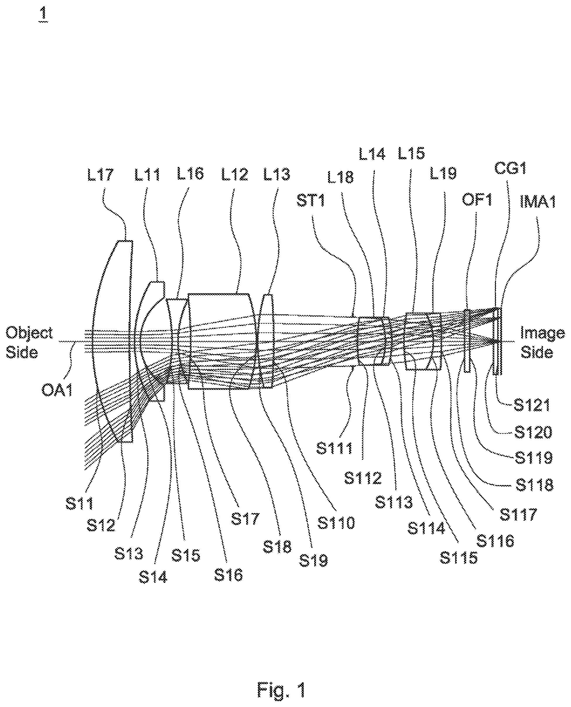
A detailed description of a wide-angle lens assembly in accordance with a first embodiment of the invention is as follows. Referring to , the wide-angle lens assembly 1 includes a seventh lens L 17 , a first lens L 11 , a sixth lens L 16 , a second lens L 12 , a third lens L 13 , a stop ST 1 , an eighth lens L 18 , a fourth lens L 14 , a fifth lens L 15 , a ninth lens L 19 , an optical filter OF 1 , and a cover glass CG 1 , all of which are arranged in order from an object side to an image side along an optical axis OA 1 . In operation, an image of light rays from the object side is formed at an image plane IMA 1 .
According to the foregoing, wherein: the seventh lens L 17 is with positive refractive power; the sixth lens L 16 is a biconcave lens with negative refractive power, wherein the object side surface S 15 is a concave surface, the image side surface S 16 is a concave surface, and the object side surface S 15 and the image side surface S 16 are spherical surfaces; the second lens L 12 is a meniscus lens, wherein the object side surface S 17 is a concave surface, the image side surface S 18 is a convex surface, and the object side surface S 17 and the image side surface S 18 are spherical surfaces; the third lens L 13 is a biconvex lens, wherein the image side surface S 110 is a convex surface; the fourth lens L 14 is a meniscus lens, wherein the image side surface S 114 is a convex surface; the fifth lens L 15 is a biconvex lens, wherein the object side surface S 115 is a convex surface and the object side surface S 115 and the image side surface S 116 are spherical surfaces; the ninth lens L 19 is a meniscus lens with negative refractive power and made of glass material, wherein the object side surface S 116 is a concave surface, the image side surface S 117 is a convex surface, and the object side surface S 116 and the image side surface S 117 are spherical surfaces; the fifth lens L 15 cemented with the ninth lens L 19 ; both of the object side surface S 118 and image side surface S 119 of the optical filter OF 1 are plane surfaces; and both of the object side surface S 120 and image side surface S 121 of the cover glass CG 1 are plane surfaces.
With the above design of the lenses and stop ST 1 and at least any one of the conditions (1)-(5) satisfied, the wide-angle lens assembly 1 can have an effective decreased total lens length, an effective decreased F-number, an effective increased resolution, an effective resisted environmental temperature change, an effective corrected aberration, and an effective corrected chromatic aberration.
If the value TTL/f of condition (1) is greater than 10 then the purpose of miniaturization of the wide-angle lens assembly is difficult to achieve. Therefore, the value TT/f must beat least less than 10. An optimal range for TTL/f is between 5.5 and 10. The wide-angle lens assembly 1 has the optimal condition for miniaturization when satisfies the condition: 5.5<TTL/f<10.
Table 1 shows the optical specification of the wide-angle lens assembly 1 in .
TABLE 1
Effective Focal Length = 4.93 mm F-number = 2.0
Total Lens Length = 47.93 mm Field of View = 81.738 degrees
Radius Effective
of Focal
Surface Curvature Thickness Length
Number (mm) (mm) Nd Vd (mm) Remark
S11 25.00 4.32 1.56 62.9 50.99 The Seventh
Lens L17
S12 166.50 0.55
S13 14.51 0.63 1.8 46.5 −13.25 The First
Lens L11
S14 6.04 3.77
S15 −19.35 0.68 1.92 20.8 −7.14 The Sixth
Lens L16
S16 10.30 1.53
S17 −42.45 7.71 1.65 50.8 31.92 The Second
Lens L12
S18 −15.11 0.09
S19 20.20 1.90 1.92 23.9 17.68 The Third
Lens L13
S110 −83.41 9.40
S111 ∞ 0.46 Stop ST1
S112 25.25 3.32 1.61 63.3 8.80 The Eighth
Lens L18
S113 −6.61 0.69 1.8 25.4 −15.38 The Fourth
Lens L14
S114 −14.70 1.41
S115 17.53 3.55 1.67 55.1 7.07 The Fifth
Lens L15
S116 −6.09 0.88 1.78 25.6 −8.82 The Ninth
Lens L19
S117 −50.92 2.80
S118 ∞ 0.55 1.51 64.1 Optical
Filter OF1
S119 ∞ 2.78
S120 ∞ 0.50 1.51 64.1 Cover Glass
CG1
S121 ∞ 0.40
Table 2 shows the parameters and condition values for conditions (1)-(5) in accordance with the first embodiment of the invention. It can be seen from Table 2 that the wide-angle lens assembly 1 of the first embodiment satisfies the conditions (1)-(5).
TABLE 2
f 7 1 −20.245 mm f 6 2 −13.7 mm
TTL/f 9.722 TTL/R 71 1.917 | f 71 /f 62 | 1.478
Vd 7 62.9 Vd 1 46.5
By the above arrangements of the lenses and stop ST 1 , the wide-angle lens assembly 1 of the first embodiment can meet the requirements of optical performance as seen in A- 2 G .
It can be seen from A that the field curvature of tangential direction and sagittal direction in the wide-angle lens assembly 1 of the first embodiment ranges from −0.01 mm to 0.04 mm. It can be seen from B that the distortion in the wide-angle lens assembly 1 of the first embodiment ranges from −8% to 0%. It can be seen from C that the lateral color in the wide-angle lens assembly 1 of the first embodiment ranges from −0.5 μm to 1.7 μm. It can be seen from D that the relative illumination in the wide-angle lens assembly 1 of the first embodiment ranges from 0.58 to 1.0. It can be seen from E that the root mean square spot radius is equal to 0.912 μm and geometrical spot radius is equal to 3.298 μm as image height is equal to 0.000 mm, the root mean square spot radius is equal to 1.479 μm and geometrical spot radius is equal to 6.950 μm as image height is equal to 2.778 mm, and the root mean square spot radius is equal to 1.893 μm and geometrical spot radius is equal to 11.756 μm as image height is equal to 3.928 mm for the wide-angle lens assembly 1 of the first embodiment. It can be seen from F that the modulation transfer function of tangential direction and sagittal direction in the wide-angle lens assembly 1 of the first embodiment ranges from 0.60 to 1.0. It can be seen from G that the through focus modulation transfer function of tangential direction and sagittal direction in the wide-angle lens assembly 1 of the first embodiment ranges from 0.0 to 0.76 as focus shift ranges from −0.05 mm to 0.05 mm.
It is obvious that the field curvature, the distortion, and the lateral color of the wide-angle lens assembly 1 of the first embodiment can be corrected effectively, and the relative illumination, the resolution and the depth of focus of the wide-angle lens assembly 1 of the first embodiment can meet the requirement. Therefore, the wide-angle lens assembly 1 of the first embodiment is capable of good optical performance.
Referring to , the wide-angle lens assembly 2 includes a seventh lens L 27 , a first lens L 21 , a sixth lens L 26 , a second lens L 22 , a third lens L 23 , a stop ST 2 , an eighth lens L 28 , a fourth lens L 24 , a fifth lens L 25 , a ninth lens L 29 , an optical filter OF 2 , and a cover glass CG 2 , all of which are arranged in order from an object side to an image side along an optical axis OA 2 . In operation, an image of light rays from the object side is formed at an image plane IMA 2 .
According to the foregoing, wherein: the seventh lens L 27 is with positive refractive power; the sixth lens L 26 is a meniscus lens with negative refractive power, wherein the object side surface S 25 is a convex surface, the image side surface S 26 is a concave surface, and the object side surface S 25 and the image side surface S 26 are spherical surfaces; the second lens L 22 is a meniscus lens, wherein the object side surface S 27 is a concave surface, the image side surface S 28 is a convex surface, and the object side surface S 27 and the image side surface S 28 are spherical surfaces; the third lens L 23 is a biconvex lens, wherein the image side surface S 210 is a convex surface; the fourth lens L 24 is a meniscus lens, wherein the image side surface S 214 is a convex surface; the fifth lens L 25 is a biconvex lens, wherein the object side surface S 215 is a convex surface and the object side surface S 215 and the image side surface S 216 are spherical surfaces; the ninth lens L 29 is a meniscus lens with negative refractive power and made of glass material, wherein the object side surface S 216 is a concave surface, the image side surface S 217 is a convex surface, and the object side surface S 216 and the image side surface S 217 are spherical surfaces; the fifth lens L 25 cemented with the ninth lens L 29 ; both of the object side surface S 218 and image side surface S 219 of the optical filter OF 2 are plane surfaces; and both of the object side surface S 220 and image side surface S 221 of the cover glass CG 2 are plane surfaces.
With the above design of the lenses and stop ST 2 and at least any one of the conditions (1)-(5) satisfied, the wide-angle lens assembly 2 can have an effective decreased total lens length, an effective decreased F-number, an effective increased resolution, an effective resisted environmental temperature change, an effective corrected aberration, and an effective corrected chromatic aberration.
If the value TTL/R 1 of condition (2) is greater than 2.6 then the total lens length is difficult to be shortened. Therefore, the value TTL/R 71 must be at least less than 2.6. An optimal range for TTL/R 71 is between 1.3 and 2.6. The wide-angle lens assembly has the optimal condition for miniaturization when satisfies the condition: 1.3<TTL/R 71 <2.6.
Table 3 shows the optical specification of the wide-angle lens assembly 2 in .
TABLE 3
Effective Focal Length = 4.93 mm F-number = 2.0
Total Lens Length = 48.81 mm Field of View = 81.720 degrees
Radius Effective
of Focal
Surface Curvature Thickness Length
Number (mm) (mm) Nd Vd (mm) Remark
S21 19.49 4.10 1.51 58.9 48.94 The
Seventh
Lens L27
S22 77.39 0.66
S23 16.35 0.70 1.8 46.5 −12.15 The First
Lens L21
S24 6.01 3.20
S25 290.60 0.68 2 19.3 −8.55 The Sixth
Lens L26
S26 8.40 1.91
S27 −29.35 7.89 1.62 39 58.248 The Second
Lens L22
S28 −17.99 0.66
S29 18.15 2.16 1.96 24.1 17.543 The Third
Lens L23
S210 −256.99 7.82
S211 ∞ 0.45 Stop ST2
S212 24.18 3.20 1.61 63.4 8.831 The Eighth
Lens L28
S213 −6.72 1.19 1.8 25.4 −15.75 The Fourth
Lens L24
S214 −15.29 1.42
S215 16.51 4.17 1.67 55.5 6.561 The Fifth
Lens L25
S216 −5.49 0.86 1.78 25.6 −7.643 The Ninth
Lens L29
S217 −64.58 2.80
S218 ∞ 0.55 1.51 64.1 Optical
Filter OF2
S219 ∞ 2.86
S220 ∞ 0.50 1.51 64.1 Cover Glass
CG2
S221 ∞ 0.40
Table 4 shows the parameters and condition values for conditions (1)-(5) in accordance with the second embodiment of the invention. It can be seen from Table 4 that the wide-angle lens assembly 2 of the second embodiment satisfies the conditions (1)-(5).
TABLE 4
f 72 −18.599 mm f 62 −13.133 mm
TTL/f 9.773 TTL/R 71 2.472 | f 71 /f 62 | 1.416
Vd 7 58.9 Vd 1 46.5
By the above arrangements of the lenses and stop ST 2 , the wide-angle lens assembly 2 of the second embodiment can meet the requirements of optical performance as seen in A- 4 G .
It can be seen from A that the field curvature of tangential direction and sagittal direction in the wide-angle lens assembly 2 of the second embodiment ranges from −0.03 mm to 0.04 mm. It can be seen from B that the distortion in the wide-angle lens assembly 2 of the second embodiment ranges from −8% to 0%. It can be seen from C that the lateral color in the wide-angle lens assembly 2 of the second embodiment ranges from −0.5 μm to 1.7 μm. It can be seen from D that the relative illumination in the wide-angle lens assembly 2 of the second embodiment ranges from 0.68 to 1.0. It can be seen from E that the root mean square spot radius is equal to 1.192 μm and geometrical spot radius is equal to 6.500 μm as image height is equal to 0.000 mm, the root mean square spot radius is equal to 2.110 μm and geometrical spot radius is equal to 11.556 μm as image height is equal to 2.778 mm, and the root mean square spot radius is equal to 3.310 μm and geometrical spot radius is equal to 15.712 μm as image height is equal to 3.928 mm for the wide-angle lens assembly 2 of the second embodiment. It can be seen from F that the modulation transfer function of tangential direction and sagittal direction in the wide-angle lens assembly 2 of the second embodiment ranges from 0.55 to 1.0. It can be seen from G that the through focus modulation transfer function of tangential direction and sagittal direction in the wide-angle lens assembly 2 of the second embodiment ranges from 0.0 to 0.75 as focus shift ranges from −0.05 mm to 0.05 mm.
It is obvious that the field curvature, the distortion, and the lateral color of the wide-angle lens assembly 2 of the second embodiment can be corrected effectively, and the relative illumination, the resolution and the depth of focus of the wide-angle lens assembly 2 of the second embodiment can meet the requirement. Therefore, the wide-angle lens assembly 2 of the second embodiment is capable of good optical performance.
Referring to , the wide-angle lens assembly 3 includes a seventh lens L 37 , a first lens L 31 , a sixth lens L 36 , a second lens L 32 , a third lens L 33 , a stop ST 3 , an eighth lens L 38 , a fourth lens L 34 , a fifth lens L 35 , a ninth lens L 39 , an optical filter OF 3 , and a cover glass CG 3 , all of which are arranged in order from an object side to an image side along an optical axis OA 3 . In operation, an image of light rays from the object side is formed at an image plane IMA 3 .
According to the foregoing, wherein: the seventh lens L 37 is with positive refractive power; the sixth lens L 36 is a biconcave lens with negative refractive power, wherein the object side surface S 35 is a concave surface, the image side surface S 36 is a concave surface, and the object side surface S 35 and the image side surface S 36 are spherical surfaces; the second lens L 32 is a meniscus lens, wherein the object side surface S 37 is a concave surface, the image side surface S 38 is a convex surface, and the object side surface S 37 and the image side surface S 38 are spherical surfaces; the third lens L 33 is a meniscus lens, wherein the image side surface S 310 is a concave surface; the fourth lens L 34 is a meniscus lens, wherein the image side surface S 314 is a convex surface; the fifth lens L 35 is a biconvex lens, wherein the object side surface S 315 is a convex surface and the object side surface S 315 and the image side surface S 316 are spherical surfaces; the ninth lens L 39 is a meniscus lens with negative refractive power and made of glass material, wherein the object side surface S 316 is a concave surface, the image side surface S 317 is a convex surface, and the object side surface S 316 and the image side surface S 317 are spherical surfaces; the fifth lens L 35 cemented with the ninth lens L 39 ; both of the object side surface S 318 and image side surface S 319 of the optical filter OF 3 are plane surfaces; and both of the object side surface S 320 and image side surface S 321 of the cover glass CG 3 are plane surfaces.
With the above design of the lenses and stop ST 3 and at least any one of the conditions (1)-(5) satisfied, the wide-angle lens assembly 3 can have an effective decreased total lens length, an effective decreased F-number, an effective increased resolution, an effective resisted environmental temperature change, an effective corrected aberration, and an effective corrected chromatic aberration.
If the value |f 71 /f 62 | of condition (3) is greater than 1.7 then the ability to balance the refractive power distribution of the object side and the middle section of the wide-angle lens is decreased. Therefore, the value |f 71 /f 62 | must be at least less than 1.7. An optimal range for |f 71 /f 62 | is between 0.03 and 1.7. The wide-angle lens assembly has the optimal condition for effective controlled field of view when satisfies the condition: 0.03<|f 71 /f 62 |<1.7.
Table 5 shows the optical specification of the wide-angle lens assembly 3 in .
TABLE 5
Effective Focal Length = 4.93 mm F-number = 2.0
Total Lens Length = 43 mm Field of View = 81.686 degrees
Radius Effective
of Focal
Surface Curvature Thickness Length
Number (mm) (mm) Nd Vd (mm) Remark
S31 26.48 4.00 1.56 62.9 54.51 The
Seventh
Lens L37
S32 168.42 0.11
S33 14.10 1.12 1.77 49.5 −15.02 The First
Lens L31
S34 6.16 3.89
S35 −29.35 0.85 1.92 20.8 −6.70 The Sixth
Lens L36
S36 8.03 1.86
S37 −125.57 7.57 1.61 49.8 25.194 The Second
Lens L32
S38 −14.21 0.10
S39 11.38 2.33 1.92 23.9 15.138 The Third
Lens L33
S310 53.89 6.32
S311 ∞ 0.27 Stop ST3
S312 40.80 2.29 1.61 63.3 7.383 The Eighth
Lens L38
S313 −5.04 1.20 1.78 26.2 −10.752 The Fourth
Lens L34
S314 −13.71 0.28
S315 13.66 2.79 1.67 55.3 6.334 The Fifth
Lens L35
S316 −5.77 1.21 1.8 25.4 −7.771 The Ninth
Lens L39
S317 −75.24 2.80
S318 ∞ 0.55 1.51 64.1 Optical
Filter OF3
S319 ∞ 2.55
S320 ∞ 0.50 1.51 64.1 Cover Glass
CG3
S321 ∞ 0.40
Table 6 shows the parameters and condition values for conditions (1)-(5) in accordance with the third embodiment of the invention. It can be seen from Table 6 that the wide-angle lens assembly 3 of the third embodiment satisfies the conditions (1)-(5).
TABLE 6
f 71 −23.259 mm f 62 −14.807 mm
TTL/f 8.722 TTL/R 71 1.624 | f 71 /f 62 | 1.571
Vd 7 62.9 Vd 1 49.5
By the above arrangements of the lenses and stop ST 3 , the wide-angle lens assembly 3 of the third embodiment can meet the requirements of optical performance as seen in A- 6 G .
It can be seen from A that the field curvature of tangential direction and sagittal direction in the wide-angle lens assembly 3 of the third embodiment ranges from −0.02 mm to 0.05 mm. It can be seen from B that the distortion in the wide-angle lens assembly 3 of the third embodiment ranges from −8% to 0%. It can be seen from C that the lateral color in the wide-angle lens assembly 3 of the third embodiment ranges from −0.5 μm to 1.3 μm. It can be seen from D that the relative illumination in the wide-angle lens assembly 3 of the third embodiment ranges from 0.73 to 1.0. It can be seen from E that the root mean square spot radius is equal to 1.141 μm and geometrical spot radius is equal to 2.847 μm as image height is equal to 0.000 mm, the root mean square spot radius is equal to 1.816 μm and geometrical spot radius is equal to 8.275 μm as image height is equal to 2.778 mm, and the root mean square spot radius is equal to 3.448 μm and geometrical spot radius is equal to 16.413 μm as image height is equal to 3.928 mm for the wide-angle lens assembly 3 of the third embodiment. It can be seen from F that the modulation transfer function of tangential direction and sagittal direction in the wide-angle lens assembly 3 of the third embodiment ranges from 0.58 to 1.0. It can be seen from G that the through focus modulation transfer function of tangential direction and sagittal direction in the wide-angle lens assembly 3 of the third embodiment ranges from 0.0 to 0.72 as focus shift ranges from −0.05 mm to 0.05 mm.
It is obvious that the field curvature, the distortion, and the lateral color of the wide-angle lens assembly 3 of the third embodiment can be corrected effectively, and the relative illumination, the resolution and the depth of focus of the wide-angle lens assembly 3 of the third embodiment can meet the requirement. Therefore, the wide-angle lens assembly 3 of the third embodiment is capable of good optical performance.
Referring to , the wide-angle lens assembly 4 includes a seventh lens L 47 , a first lens L 41 , a sixth lens L 46 , a second lens L 42 , a third lens L 43 , a stop ST 4 , an eighth lens L 48 , a fourth lens L 44 , a fifth lens L 45 , a ninth lens L 49 , and a cover glass CG 4 , all of which are arranged in order from an object side to an image side along an optical axis OA 4 . In operation, an image of light rays from the object side is formed at an image plane IMA 4 .
According to the foregoing, wherein: the seventh lens L 47 is with positive refractive power; the sixth lens L 46 is a biconcave lens with negative refractive power, wherein the object side surface S 45 is a concave surface, the image side surface S 46 is a concave surface, and the object side surface S 45 and the image side surface S 46 are spherical surfaces; the second lens L 42 is a meniscus lens, wherein the object side surface S 47 is a concave surface, the image side surface S 48 is a convex surface, and the object side surface S 47 and the image side surface S 48 are spherical surfaces; the third lens L 43 is a biconvex lens, wherein the image side surface S 410 is a convex surface; the fourth lens L 44 is a meniscus lens, wherein the image side surface S 414 is a convex surface; the fifth lens L 45 is a biconvex lens, wherein the object side surface S 415 is a convex surface and the object side surface S 415 and the image side surface S 416 are spherical surfaces; the ninth lens L 49 is a meniscus lens with negative refractive power and made of glass material, wherein the object side surface S 416 is a concave surface, the image side surface S 417 is a convex surface, and the object side surface S 416 and the image side surface S 417 are spherical surfaces; the fifth lens L 45 cemented with the ninth lens L 49 ; and both of the object side surface S 418 and image side surface S 419 of the cover glass CG 4 are plane surfaces.
With the above design of the lenses and stop ST 4 and at least any one of the conditions (1)-(5) satisfied, the wide-angle lens assembly 4 can have an effective decreased total lens length, an effective decreased F-number, an effective increased resolution, an effective resisted environmental temperature change, an effective corrected aberration, and an effective corrected chromatic aberration.
If the value Vd 7 of condition (4) is less than 30 then the ability of achromatic function is poor. Therefore, the value Vd 7 must be at least greater than 30. An optimal range for Vd 7 is between 30 and 64.3. The wide-angle lens assembly has the optimal condition for effective reduced chromatic aberration when satisfies the condition: 30<Vd 7 <64.3.
Table 7 shows the optical specification of the wide-angle lens assembly 4 in .
TABLE 7
Effective Focal Length = 4.93 mm F-number = 2.0
Total Lens Length = 47.86 mm Field of View = 81.704 degrees
Effective
Radius of Focal
Surface Curvature Thickness Length
Number (mm) (mm) Nd Vd (mm) Remark
S41 23.37 4.05 1.58 61.2 48.90 The Seventh Lens L47
S42 114.31 0.57
S43 15.78 1.06 1.77 49.5 −13.34 The First Lens L41
S44 6.06 3.59
S45 −27.28 0.67 1.92 20.8 −7.37 The Sixth Lens L46
S46 9.28 1.65
S47 −39.56 7.93 1.65 56.1 36.006 The Second Lens L42
S48 −15.92 0.09
S49 18.02 1.83 1.92 23.9 17.744 The Third Lens L43
S410 −181.85 8.45
S411 ∞ 0.48 Stop ST4
S412 25.34 4.30 1.61 63.3 8.805 The Eighth Lens L48
S413 −6.50 0.71 1.8 25.4 −14.562 The Fourth Lens L44
S414 −15.19 1.43
S415 14.73 3.27 1.67 55.1 6.879 The Fifth Lens L45
S416 −6.24 0.82 1.78 25.6 −8.852 The Ninth Lens L49
S417 −61.29 5.51
S418 ∞ 1.05 1.51 64.1 Cover Glass CG4
S419 ∞ 0.40
Table 8 shows the parameters and condition values for conditions (1)-(5) in accordance with the fourth embodiment of the invention. It can be seen from Table 8 that the wide-angle lens assembly 4 of the fourth embodiment satisfies the conditions (1)-(5).
TABLE 8
f 71 −21.151 mm f 62 −13.404 mm
TTL/f 9.708 TTL/R 71 2.048 | f 71 /f 62 | 1.578
Vd 7 61.2 Vd 1 49.5
By the above arrangements of the lenses and stop ST 4 , the wide-angle lens assembly 4 of the fourth embodiment can meet the requirements of optical performance as seen in A- 8 G .
It can be seen from A that the field curvature of tangential direction and sagittal direction in the wide-angle lens assembly 4 of the fourth embodiment ranges from −0.015 mm to 0.035 mm. It can be seen from B that the distortion in the wide-angle lens assembly 4 of the fourth embodiment ranges from −8% to 0%. It can be seen from C that the lateral color in the wide-angle lens assembly 4 of the fourth embodiment ranges from −0.6 μm to 1.6 μm. It can be seen from D that the relative illumination in the wide-angle lens assembly 4 of the fourth embodiment ranges from 0.58 to 1.0. It can be seen from E that the root mean square spot radius is equal to 0.824 μm and geometrical spot radius is equal to 3.083 μm as image height is equal to 0.000 mm, the root mean square spot radius is equal to 1.389 μm and geometrical spot radius is equal to 6.870 μm as image height is equal to 2.750 mm, and the root mean square spot radius is equal to 1.973 μm and geometrical spot radius is equal to 11.821 μm as image height is equal to 3.928 mm for the wide-angle lens assembly 4 of the fourth embodiment. It can be seen from F that the modulation transfer function of tangential direction and sagittal direction in the wide-angle lens assembly 4 of the fourth embodiment ranges from 0.58 to 1.0. It can be seen from G that the through focus modulation transfer function of tangential direction and sagittal direction in the wide-angle lens assembly 4 of the fourth embodiment ranges from 0.0 to 0.72 as focus shift ranges from −0.05 mm to 0.05 mm.
It is obvious that the field curvature, the distortion, and the lateral color of the wide-angle lens assembly 4 of the fourth embodiment can be corrected effectively, and the relative illumination, the resolution and the depth of focus of the wide-angle lens assembly 4 of the fourth embodiment can meet the requirement. Therefore, the wide-angle lens assembly 4 of the fourth embodiment is capable of good optical performance.
Referring to , the wide-angle lens assembly 5 includes a seventh lens L 57 , a first lens L 51 , a sixth lens L 56 , a second lens L 52 , a third lens L 53 , a stop ST 5 , an eighth lens L 58 , a fourth lens L 54 , a fifth lens L 55 , a ninth lens L 59 , a tenth lens L 510 , and a cover glass CG 5 , all of which are arranged in order from an object side to an image side along an optical axis OA 5 . In operation, an image of light rays from the object side is formed at an image plane IMA 5 .
According to the foregoing, wherein: the seventh lens L 57 is with positive refractive power; the sixth lens L 56 is a biconcave lens with negative refractive power, wherein the object side surface S 55 is a concave surface, the image side surface S 56 is a concave surface, and the object side surface S 55 and the image side surface S 56 are spherical surfaces; the second lens L 52 is a biconvex lens, wherein the object side surface S 57 is a convex surface, the image side surface S 58 is a convex surface, and the object side surface S 57 and the image side surface S 58 are spherical surfaces; the third lens L 53 is a meniscus lens, wherein the image side surface S 510 is a concave surface; the fourth lens L 54 is a biconcave lens, wherein the image side surface S 514 is a concave surface; the fifth lens L 55 is a biconvex lens, wherein the object side surface S 515 is a convex surface and the object side surface S 515 and the image side surface S 516 are spherical surfaces; the ninth lens L 59 is a biconcave lens with negative refractive power and made of glass material, wherein the object side surface S 517 is a concave surface, the image side surface S 518 is a concave surface, and the object side surface S 517 and the image side surface S 518 are spherical surfaces; the tenth lens L 510 is a biconvex lens with positive refractive power and made of glass material, wherein the object side surface S 519 is a convex surface, the image side surface S 520 is a convex surface, and the object side surface S 519 and the image side surface S 520 are spherical surfaces; and both of the object side surface S 521 and image side surface S 522 of the cover glass CG 5 are plane surfaces.
With the above design of the lenses and stop ST 5 and at least any one of the conditions (1)-(5) satisfied, the wide-angle lens assembly 5 can have an effective decreased total lens length, an effective decreased F-number, an effective increased resolution, an effective resisted environmental temperature change, an effective corrected aberration, and an effective corrected chromatic aberration.
If the condition (1): 5.5<TTL/f<10 is satisfied, thereby enhancing the features of the positive refractive power and the shape configuration of the object side surface S 59 of the third lens L 53 , the positive refractive power and shape configuration on the object side S 512 and image side S 513 of the eighth lens L 58 , the fourth lens L 54 and shape configuration on the object side S 513 of the fourth lens L 54 , and the fifth lens L 55 and shape configuration on the image side surface S 516 of the fifth lens L 55 to effective balanced the field of view and the total lens length of the wide-angle lens assembly. If conditions (2) and (3): 1.3<TTL/R 71 <2.6; 0.03<|f 71 /f 62 <1.7 are satisfied, thereby with combining the stop is to be disposed between the seventh lens and the image plane enhancing the features of the shape configuration of the seventh lens L 57 , the object side surface S 51 , the image side surface S 52 , the first lens L 51 with negative refractive power, the object side surface S 53 , and the image side surface S 54 to strengthen the miniaturization, effectively control the field of view, help achieving a balance between F-number, field of view and total lens length for the wide-angle lens assembly. If the conditions (4) and (5): 30<Vd 7 <64.3; 35<Vd 1 <54.5 are satisfied, thereby strengthening the ability of achromatic function for the seventh lens L 57 and the first lens L 51 .
Table 9 shows the optical specification of the wide-angle lens assembly 5 in .
TABLE 9
Effective Focal Length = 4.93 mm F-number = 2.0
Total Lens Length = 42.06 mm Field of View = 81.704 degrees
Effective
Radius of Thick- Focal
Surface Curvature ness Length
Number (mm) (mm) Nd Vd (mm) Remark
S51 25.76 3.71 1.67 55.2 47.93 The Seventh Lens L57
S52 115.59 0.07
S53 17.95 0.92 1.8 40.9 −12.36 The First Lens L51
S54 6.28 4.75
S55 −14.96 1.02 1.7 41.1 −9.41 The Sixth Lens L56
S56 12.23 5.42
S57 40.79 3.55 1.61 63.3 17.068 The Second Lens L52
S58 −13.81 0.06
S59 11.01 1.95 1.9 31.3 22.16 The Third Lens L53
S510 22.25 7.19
S511 ∞ 0.00 Stop STS
S512 6.84 2.08 1.69 55.5 4.952 The Eighth Lens L58
S513 −6.14 1.20 1.78 25.6 −3.585 The Fourth Lens L54
S514 5.72 0.38
S515 11.25 1.77 1.9 37 6.919 The Fifth Lens L55
S516 −13.07 0.43
S517 -7.31 0.64 1.76 26.5 −7.231 The Ninth Lens L59
S518 23.83 1.05
S519 9.20 2.56 1.9 31.3 8.32 The Tenth Lens L510
S520 −36.76 1.93
S521 ∞ 1.00 1.51 64.1 Cover Glass CG5
S522 ∞ 0.40
Table 10 shows the parameters and condition values for conditions (1)-(5) in accordance with the fifth embodiment of the invention. It can be seen from Table 10 that the wide-angle lens assembly 5 of the fifth embodiment satisfies the conditions (1)-(5).
TABLE 10
f 71 −18.568 mm f 62 −527.76 mm
TTL/f 8.531 TTL/R 71 1.633 | f 71 /f 62 | 0.035
Vd 7 55.2 Vd 1 40.9
By the above arrangements of the lenses and stop ST 5 , the wide-angle lens assembly 5 of the fifth embodiment can meet the requirements of optical performance as seen in A- 10 G .
It can be seen from A that the field curvature of tangential direction and sagittal direction in the wide-angle lens assembly 5 of the fifth embodiment ranges from −0.02 mm to 0.03 mm. It can be seen from B that the distortion in the wide-angle lens assembly 5 of the fifth embodiment ranges from −8% to 0%. It can be seen from C that the lateral color in the wide-angle lens assembly 5 of the fifth embodiment ranges from −0.3 μm to 1.6 μm. It can be seen from D that the relative illumination in the wide-angle lens assembly 5 of the fifth embodiment ranges from 0.69 to 1.0. It can be seen from E that the root mean square spot radius is equal to 0.787 μm and geometrical spot radius is equal to 3.168 μm as image height is equal to 0.000 mm, the root mean square spot radius is equal to 1.114 μm and geometrical spot radius is equal to 6.010 μm as image height is equal to 2.750 mm, and the root mean square spot radius is equal to 2.082 μm and geometrical spot radius is equal to 9.702 μm as image height is equal to 3.928 mm for the wide-angle lens assembly 5 of the fifth embodiment. It can be seen from F that the modulation transfer function of tangential direction and sagittal direction in the wide-angle lens assembly 5 of the fifth embodiment ranges from 0.59 to 1.0. It can be seen from G that the through focus modulation transfer function of tangential direction and sagittal direction in the wide-angle lens assembly 5 of the fifth embodiment ranges from 0.0 to 0.72 as focus shift ranges from −0.05 mm to 0.05 mm.
It is obvious that the field curvature, the distortion, and the lateral color of the wide-angle lens assembly 5 of the fifth embodiment can be corrected effectively, and the relative illumination, the resolution and the depth of focus of the wide-angle lens assembly 5 of the fifth embodiment can meet the requirement. Therefore, the wide-angle lens assembly 5 of the fifth embodiment is capable of good optical performance.
Referring to , the wide-angle lens assembly 6 includes a seventh lens L 67 , a first lens L 61 , a sixth lens L 66 , a second lens L 62 , a third lens L 63 , a stop ST 6 , an eighth lens L 68 , a fourth lens L 64 , a fifth lens L 65 , and a cover glass CG 6 , all of which are arranged in order from an object side to an image side along an optical axis OA 6 . In operation, an image of light rays from the object side is formed at an image plane IMA 6 .
According to the foregoing, wherein: the seventh lens L 67 is with positive refractive power; the sixth lens L 66 is a biconcave lens with negative refractive power, wherein the object side surface S 65 is a concave surface, the image side surface S 66 is a concave surface, and the object side surface S 65 and the image side surface S 66 are spherical surfaces; the second lens L 62 is a biconvex lens, wherein the object side surface S 67 is a convex surface, the image side surface S 68 is a convex surface, and the object side surface S 67 and the image side surface S 68 are spherical surfaces; the third lens L 63 is a meniscus lens, wherein the image side surface S 610 is a concave surface; the fourth lens L 64 is a biconcave lens, wherein the image side surface S 614 is a concave surface; the fifth lens L 65 is a biconvex lens, wherein the object side surface S 615 is a convex surface and the object side surface S 615 and the image side surface S 616 are aspheric surfaces; and both of the object side surface S 617 and image side surface S 618 of the cover glass CG 6 are plane surfaces.
With the above design of the lenses and stop ST 6 and at least any one of the conditions (1)-(5) satisfied, the wide-angle lens assembly 6 can have an effective decreased total lens length, an effective decreased F-number, an effective increased resolution, an effective resisted environmental temperature change, an effective corrected aberration, and an effective corrected chromatic aberration.
If the value Vd 1 of condition (5) is less than 35 then the ability of achromatic function is poor. Therefore, the value Vd 1 must be at least greater than 35. An optimal range for Vd 1 is between 35 and 54.5. The wide-angle lens assembly has the optimal condition for effective reduced chromatic aberration when satisfies the condition: 35<Vd 1 <54.5.
Table 11 shows the optical specification of the wide-angle lens assembly 6 in .
TABLE 11
Effective Focal Length = 4.93 mm F-number = 2.0
Total Lens Length = 46.6 mm Field of View = 81.688 degrees
Effective
Radius of Thick- Focal
Surface Curvature ness Length
Number (mm) (mm) Nd Vd (mm) Remark
S61 26.40 4.21 1.56 62.9 54.00 The Seventh Lens L67
S62 173.97 0.24
S63 19.26 0.78 1.71 53.8 −15.47 The First Lens L61
S64 6.91 4.03
S65 −28.46 0.92 1.92 23.9 −7.97 The Sixth Lens L66
S66 10.14 7.14
S67 66.19 4.04 1.61 63.3 23.153 The Second Lens L62
S68 −17.89 0.10
S69 15.10 2.33 1.92 23.9 22.714 The Third Lens L63
S610 49.24 7.64
S611 ∞ 0.80 Stop ST6
S612 9.76 2.91 1.72 54 5.134 The Eighth Lens L68
S613 −5.34 0.78 1.76 26.6 −3.874 The Fourth Lens L64
S614 7.13 0.37
S615 11.22 2.93 1.64 58.1 9.444 The Fifth Lens L65
S616 −12.17 5.97
S617 ∞ 1.00 1.51 64.1 Cover Glass CG6
S618 ∞ 0.40
The aspheric surface sag z of each aspheric lens in table 11 can be calculated by the following formula: z=ch 2 /{1+[1−( k+ 1) c 2 h 2 ] 1/2 }+Ah 4 +Bh 6 +Ch 8
•
• where c is curvature, h is the vertical distance from the lens surface to the optical axis, k is conic constant and A, B and C are aspheric coefficients.
In the sixth embodiment, the conic constant k and the aspheric coefficients A, B, C of each aspheric lens are shown in Table 12.
TABLE 12
Surface
Number k A B C
S615 −4.602692 −0.000547 −2.26E−05 −3.00E−06
S616 8.75262 −5.50E−07 −6.58E−06 5.57E−07
Table 13 shows the parameters and condition values for conditions (1)-(5) in accordance with the sixth embodiment of the invention. It can be seen from Table 13 that the wide-angle lens assembly 6 of the sixth embodiment satisfies the conditions (1)-(5).
TABLE 13
f 71 −24.246 mm f 62 −31.159 mm
TTL/f 9.452 TTL/R 71 1.765 | f 71 /f 62 | 0.778
Vd 7 62.9 Vd 1 53.8
By the above arrangements of the lenses and stop ST 6 , the wide-angle lens assembly 6 of the sixth embodiment can meet the requirements of optical performance as seen in A- 12 G .
It can be seen from A that the field curvature of tangential direction and sagittal direction in the wide-angle lens assembly 6 of the sixth embodiment ranges from −0.02 mm to 0.035 mm. It can be seen from B that the distortion in the wide-angle lens assembly 6 of the sixth embodiment ranges from −8% to 0%. It can be seen from C that the lateral color in the wide-angle lens assembly 6 of the sixth embodiment ranges from −0.5 μm to 1.4 μm. It can be seen from D that the relative illumination in the wide-angle lens assembly 6 of the sixth embodiment ranges from 0.60 to 1.0. It can be seen from E that the root mean square spot radius is equal to 1.052 μm and geometrical spot radius is equal to 3.992 μm as image height is equal to 0.000 mm, the root mean square spot radius is equal to 1.153 μm and geometrical spot radius is equal to 6.678 μm as image height is equal to 2.750 mm, and the root mean square spot radius is equal to 1.821 μm and geometrical spot radius is equal to 10.259 μm as image height is equal to 3.928 mm for the wide-angle lens assembly 6 of the sixth embodiment. It can be seen from F that the modulation transfer function of tangential direction and sagittal direction in the wide-angle lens assembly 6 of the sixth embodiment ranges from 0.56 to 1.0. It can be seen from G that the through focus modulation transfer function of tangential direction and sagittal direction in the wide-angle lens assembly 6 of the sixth embodiment ranges from 0.0 to 0.72 as focus shift ranges from −0.05 mm to 0.05 mm.
It is obvious that the field curvature, the distortion, and the lateral color of the wide-angle lens assembly 6 of the sixth embodiment can be corrected effectively, and the relative illumination, the resolution and the depth of focus of the wide-angle lens assembly 6 of the sixth embodiment can meet the requirement. Therefore, the wide-angle lens assembly 6 of the sixth embodiment is capable of good optical performance.
Referring to , the wide-angle lens assembly 7 includes a seventh lens L 77 , a first lens L 71 , a sixth lens L 76 , a second lens L 72 , a stop ST 7 , a third lens L 73 , an eighth lens L 78 , a fourth lens L 74 , a fifth lens L 75 , a ninth lens L 79 , an optical filter OF 7 , and a cover glass CG 7 , all of which are arranged in order from an object side to an image side along an optical axis OA 7 . In operation, an image of light rays from the object side is formed at an image plane IMA 7 .
According to the foregoing, wherein: the seventh lens L 77 is with negative refractive power; the sixth lens L 76 is a meniscus lens with positive refractive power, wherein the object side surface S 75 is a concave surface, the image side surface S 76 is a convex surface, and the object side surface S 75 and the image side surface S 76 are aspheric surfaces; the second lens L 72 is a meniscus lens, wherein the object side surface S 77 is a convex surface, the image side surface S 78 is a concave surface, and the object side surface S 77 and the image side surface S 78 are aspheric surfaces; the third lens L 73 is a biconvex lens, wherein the image side surface S 711 is a convex surface; the fourth lens L 74 is a biconcave lens, wherein the image side surface S 714 is a concave surface; the fifth lens L 75 is a meniscus lens, wherein the object side surface S 715 is a concave surface and the object side surface S 715 and the image side surface S 716 are aspheric surfaces; the ninth lens L 79 is a meniscus lens with negative refractive power and made of glass material, wherein the object side surface S 717 is a concave surface, the image side surface S 718 is a convex surface, and the object side surface S 717 and the image side surface S 718 are spherical surfaces; both of the object side surface S 719 and image side surface S 720 of the optical filter OF 7 are plane surfaces; and both of the object side surface S 721 and image side surface S 722 of the cover glass CG 7 are plane surfaces.
With the above design of the lenses and stop ST 7 and at least any one of the conditions (1)-(5) satisfied, the wide-angle lens assembly 7 can have an effective decreased total lens length, an effective decreased F-number, an effective increased resolution, an effective resisted environmental temperature change, an effective corrected aberration, and an effective corrected chromatic aberration.
Table 14 shows the optical specification of the wide-angle lens assembly 7 in .
TABLE 14
Effective Focal Length = 5.3 mm F-number = 3.0
Total Lens Length = 40.0 mm Field of View = 159.452 degrees
Effective
Radius of Focal
Surface Curvature Thickness Length
Number (mm) (mm) Nd Vd (mm) Remark
S71 26.59 0.80 1.91 35.25 −15.40 The Seventh Lens L77
S72 9.08 2.74
S73 14.20 0.70 1.88 40.77 −15.50 The First Lens L71
S74 6.82 5.02
S75 −24.04 8.63 1.52 64.05 23.20 The Sixth Lens L76
S76 -9.00 0.10
S77 9.30 2.81 1.71 29.67 39.9 The Second Lens L72
S78 12.04 4.06
S79 ∞ 0.10 Stop ST7
S710 41.27 1.67 1.5 81.61 16.3 The Third Lens L73
S711 −10.01 0.50
S712 10.19 2.29 1.5 81.61 9.3 The Eighth Lens L78
S713 −7.92 0.60 1.85 23.78 −7.4 The Fourth Lens L74
S714 32.85 1.37
S715 −12.72 1.40 1.81 40.25 18.4 The Fifth Lens L75
S716 −7.19 1.61
S717 −5.69 0.80 1.85 23.78 −20.3 The Ninth Lens L79
S718 −9.03 2.00
S719 ∞ 0.30 1.52 64.17 Optical Filter OF7
S720 ∞ 0.80
S721 ∞ 0.50 1.52 64.17 Cover Glass CG7
S722 ∞ 1.20
The definition of aspheric surface sag z of each aspheric lens in table 14 is the same as that of in Table 11, and is not described here again.
In the seventh embodiment, the conic constant k and the aspheric coefficients A, B, C of each aspheric lens are shown in Table 15.
TABLE 15
Surface
Number k A B C
S75 11.78259 2.70E−05 −6.49E−07 2.32E−08
S76 0 2.72E−04 −2.43E−06 2.20E−08
S77 0 −7.49E−05 3.05E−06 4.20E−08
S78 0 −2.59E−04 1.52E−05 1.72E−07
S715 0 −6.47E−04 −2.17E−05 3.86E−07
S716 0 −3.55E−04 −1.67E−05 4.51E−09
Table 16 shows the parameters and condition values for conditions (1)-(5) in accordance with the seventh embodiment of the invention. It can be seen from Table 16 that the wide-angle lens assembly 7 of the seventh embodiment satisfies the conditions (1)-(5).
TABLE 16
f 71 −6.99 mm f 62 13.28 mm
TTL/f 7.547 TTL/R 71 1.504 | f 71 /f 62 | 0.526
Vd 7 35.3 Vd 1 40.8
By the above arrangements of the lenses and stop ST 7 , the wide-angle lens assembly 7 of the seventh embodiment can meet the requirements of optical performance as seen in A- 14 E .
It can be seen from A that the longitudinal aberration in the wide-angle lens assembly 7 of the seventh embodiment ranges from −0.015 mm to 0.03 mm. It can be seen from B that the field curvature of tangential direction and sagittal direction in the wide-angle lens assembly 7 of the seventh embodiment ranges from −0.04 mm to 0.06 mm. It can be seen from C that the distortion in the wide-angle lens assembly 7 of the seventh embodiment ranges from −80% to 0%. It can be seen from D that the lateral color in the wide-angle lens assembly 7 of the seventh embodiment ranges from 0 μm to 4.0 μm. It can be seen from E that the modulation transfer function of tangential direction and sagittal direction in the wide-angle lens assembly 7 of the seventh embodiment ranges from 0.48 to 1.0.
It is obvious that the longitudinal aberration, the field curvature, the distortion, and the lateral color of the wide-angle lens assembly 7 of the seventh embodiment can be corrected effectively, and the resolution of the wide-angle lens assembly 7 of the seventh embodiment can meet the requirement. Therefore, the wide-angle lens assembly 7 of the seventh embodiment is capable of good optical performance.
Referring to , the wide-angle lens assembly 8 includes a seventh lens L 87 , a first lens L 81 , a sixth lens L 86 , a second lens L 82 , a stop ST 8 , a third lens L 83 , an eighth lens L 88 , a fourth lens L 84 , a fifth lens L 85 , a ninth lens L 89 , an optical filter OF 8 , and a cover glass CG 8 , all of which are arranged in order from an object side to an image side along an optical axis OA 8 . In operation, an image of light rays from the object side is formed at an image plane IMA 8 .
According to the foregoing, wherein: the seventh lens L 87 is with negative refractive power; the sixth lens L 86 is a meniscus lens with positive refractive power, wherein the object side surface S 85 is a concave surface, the image side surface S 86 is a convex surface, and the object side surface S 85 and the image side surface S 86 are aspheric surfaces; the second lens L 82 is a meniscus lens, wherein the object side surface S 87 is a convex surface, the image side surface S 88 is a concave surface, and the object side surface S 87 and the image side surface S 88 are aspheric surfaces; the third lens L 83 is a biconvex lens, wherein the image side surface S 811 is a convex surface; the fourth lens L 84 is a meniscus lens, wherein the image side surface S 814 is a convex surface; the fifth lens L 85 is a meniscus lens, wherein the object side surface S 815 is a concave surface and the object side surface S 815 and the image side surface S 816 are aspheric surfaces; the ninth lens L 89 is a meniscus lens with negative refractive power and made of glass material, wherein the object side surface S 817 is a concave surface, the image side surface S 818 is a convex surface, and the object side surface S 817 and the image side surface S 818 are spherical surfaces; both of the object side surface S 819 and image side surface S 820 of the optical filter OF 8 are plane surfaces; and both of the object side surface S 821 and image side surface S 822 of the cover glass CG 8 are plane surfaces.
With the above design of the lenses and stop ST 8 and at least any one of the conditions (1)-(5) satisfied, the wide-angle lens assembly 8 can have an effective decreased total lens length, an effective decreased F-number, an effective increased resolution, an effective resisted environmental temperature change, an effective corrected aberration, and an effective corrected chromatic aberration.
Table 17 shows the optical specification of the wide-angle lens assembly 8 in .
TABLE 17
Effective Focal Length = 5.3 mm F-number = 3.0
Total Lens Length = 40.02 mm Field of View = 159.534 degrees
Effective
Radius of Focal
Surface Curvature Thickness Length
Number (mm) (mm) Nd Vd (mm) Remark
S81 25.65 1.41 1.91 35.25 −16.70 The Seventh Lens L87
S82 9.33 2.95
S83 15.33 0.70 1.88 40.77 −14.60 The First Lens L81
S84 6.86 5.61
S85 −13.78 5.76 1.52 64.05 34.70 The Sixth Lens L86
S86 −8.91 0.10
S87 8.24 3.94 1.71 29.67 56 The Second Lens L82
S88 8.29 3.50
S89 ∞ 0.10 Stop ST8
S810 10.83 3.19 1.5 81.61 10.2 The Third Lens L83
S811 −8.60 0.50
S812 15.82 2.51 1.5 81.61 9.8 The Eighth Lens L88
S813 −6.71 0.60 1.85 23.78 −9.2 The Fourth Lens L84
S814 −46.45 1.38
S815 −6.86 1.05 1.81 40.25 40.8 The Fifth Lens L85
S816 −6.06 1.12
S817 −5.74 0.80 1.85 23.78 −20.5 The Ninth Lens L89
S818 −9.08 2.00
S819 ∞ 0.30 1.52 64.17 Optical Filter OF8
S820 ∞ 0.80
S821 ∞ 0.50 1.52 64.17 Cove Glass CG8
S822 ∞ 1.20
The definition of aspheric surface sag z of each aspheric lens in table 17 is the same as that of in Table 11, and is not described here again.
In the eighth embodiment, the conic constant k and the aspheric coefficients A, B, C of each aspheric lens are shown in Table 18.
TABLE 18
Surface
Number k A B C
S85 2.943 1.61E−04 −3.81E−06 6.26E−08
S86 0 1.19E−04 5.23E−07 −5.81E−09
S87 0 −5.84E−05 9.55E−07 1.84E−07
S88 0 1.93E−04 1.31E−06 2.47E−06
S815 0 2.44E−04 4.21E−05 −3.41E−08
S816 0 4.62E−04 2.70E−05 5.90E−07
Table 19 shows the parameters and condition values for conditions (1)-(5) in accordance with the eighth embodiment of the invention. It can be seen from Table 19 that the wide-angle lens assembly 8 of the eighth embodiment satisfies the conditions (1)-(5).
TABLE 19
f 71 −7.06 mm f 62 18.22 mm
TTL/f 7.551 TTL/R 71 1.560 | f 71 /f 62 | 0.387
Vd 7 35.3 Vd 1 40.8
By the above arrangements of the lenses and stop ST 8 , the wide-angle lens assembly 8 of the eighth embodiment can meet the requirements of optical performance as seen in A- 16 E .
It can be seen from A that the longitudinal aberration in the wide-angle lens assembly 8 of the eighth embodiment ranges from −0.01 mm to 0.025 mm. It can be seen from B that the field curvature of tangential direction and sagittal direction in the wide-angle lens assembly 8 of the eighth embodiment ranges from −0.04 mm to 0.06 mm. It can be seen from C that the distortion in the wide-angle lens assembly 8 of the eighth embodiment ranges from −80% to 0%. It can be seen from D that the lateral color in the wide-angle lens assembly 8 of the eighth embodiment ranges from 0 μm to 3.5 μm. It can be seen from E that the modulation transfer function of tangential direction and sagittal direction in the wide-angle lens assembly 8 of the eighth embodiment ranges from 0.49 to 1.0.
It is obvious that the longitudinal aberration, the field curvature, the distortion, and the lateral color of the wide-angle lens assembly 8 of the eighth embodiment can be corrected effectively, and the resolution of the wide-angle lens assembly 8 of the eighth embodiment can meet the requirement. Therefore, the wide-angle lens assembly 8 of the eighth embodiment is capable of good optical performance.
Referring to , the wide-angle lens assembly 9 includes a seventh lens L 97 , a first lens L 91 , a sixth lens L 96 , a second lens L 92 , a stop ST 9 , a third lens L 93 , an eighth lens L 98 , a fourth lens L 94 , a fifth lens L 95 , a ninth lens L 99 , an optical filter OF 9 , and a cover glass CG 9 , all of which are arranged in order from an object side to an image side along an optical axis OA 9 . In operation, an image of light rays from the object side is formed at an image plane IMA 9 .
According to the foregoing, wherein: the seventh lens L 97 is with negative refractive power; the sixth lens L 96 is a meniscus lens with positive refractive power, wherein the object side surface S 95 is a concave surface, the image side surface S 96 is a convex surface, and the object side surface S 95 and the image side surface S 96 are aspheric surfaces; the second lens L 92 is a meniscus lens, wherein the object side surface S 97 is a convex surface, the image side surface S 98 is a concave surface, and the object side surface S 97 and the image side surface S 98 are aspheric surfaces; the third lens L 93 is a biconvex lens, wherein the image side surface S 911 is a convex surface; the fourth lens L 94 is a meniscus lens, wherein the image side surface S 914 is a convex surface; the fifth lens L 95 is a meniscus lens, wherein the object side surface S 915 is a concave surface and the object side surface S 915 and the image side surface S 916 are aspheric surfaces; the ninth lens L 99 is a meniscus lens with negative refractive power and made of glass material, wherein the object side surface S 917 is a concave surface, the image side surface S 918 is a convex surface, and the object side surface S 917 and the image side surface S 918 are spherical surfaces; both of the object side surface S 919 and image side surface S 920 of the optical filter OF 9 are plane surfaces; and both of the object side surface S 921 and image side surface S 922 of the cover glass CG 9 are plane surfaces.
With the above design of the lenses and stop ST 9 and at least any one of the conditions (1)-(5) satisfied, the wide-angle lens assembly 9 can have an effective decreased total lens length, an effective decreased F-number, an effective increased resolution, an effective resisted environmental temperature change, an effective corrected aberration, and an effective corrected chromatic aberration.
Table 20 shows the optical specification of the wide-angle lens assembly 9 in .
TABLE 20
Effective Focal Length = 5.3 mm F-number = 3.0
Total Lens Length = 31.01 mm Field of View = 159.616 degrees
Effective
Radius of Focal
Surface Curvature Thickness Length
Number (mm) (mm) Nd Vd (mm) Remark
S91 21.13 0.80 1.91 35.25 −11.30 The Seventh Lens L97
S92 6.81 1.80
S93 9.08 0.70 1.88 40.77 −16.50 The First Lens L91
S94 5.40 4.96
S95 −7.78 3.11 1.52 64.05 37.30 The Sixth Lens L96
S96 −6.31 0.10
S97 6.67 2.11 1.71 29.67 21.60 The Second Lens L92
S98 10.14 3.00
S99 ∞ 0.10 Stop ST9
S910 13.09 1.41 1.5 81.61 11.1 The Third Lens L93
S911 −9.24 0.50
S912 19.36 2.28 1.5 81.61 8.2 The Eighth Lens L98
S913 −5.01 0.60 1.85 23.78 −7.6 The Fourth Lens L94
S914 −23.86 0.61
S915 −6.65 1.12 1.81 40.25 22.8 The Fifth Lens L95
S916 −5.25 0.93
S917 −5.47 0.80 1.85 23.78 −18.2 The Ninth Lens L99
S918 −9.02 2.00
S919 ∞ 0.30 1.52 64.17 Optical Filter OF9
S920 ∞ 2.08
S921 ∞ 0.50 1.52 64.17 Cover Glass CG9
S922 ∞ 1.20
The definition of aspheric surface sag z of each aspheric lens in table 20 is the same as that of in Table 11, and is not described here again.
In the ninth embodiment, the conic constant k and the aspheric coefficients A, B, C of each aspheric lens are shown in Table 21.
TABLE 21
Surface
Number k A B C
S95 1.078 7.67E−04 −5.67E−05 1.85E−06
S96 0 1.64E−04 7.15E−06 2.14E−07
S97 0 −7.08E−04 −6.32E−07 3.05E−06
S98 0 −5.78E−04 −1.26E−05 8.43E−06
S915 0 2.31E−04 1.31E−04 1.85E−07
S916 0 8.07E−04 6.72E−05 3.66E−06
Table 22 shows the parameters and condition values for conditions (1)-(5) in accordance with the ninth embodiment of the invention. It can be seen from Table 22 that the wide-angle lens assembly 9 of the ninth embodiment satisfies the conditions (1)-(5).
TABLE 22
f 71 −6.12 mm f 62 12.27 mm
TTL/f 5.851 TTL/R 71 1.468 | f 71 /f 62 | 0.498
Vd 7 35.3 Vd 1 40.8
By the above arrangements of the lenses and stop ST 9 , the wide-angle lens assembly 9 of the ninth embodiment can meet the requirements of optical performance as seen in A- 18 E .
It can be seen from A that the longitudinal aberration in the wide-angle lens assembly 9 of the ninth embodiment ranges from −0.01 mm to 0.03 mm. It can be seen from B that the field curvature of tangential direction and sagittal direction in the wide-angle lens assembly 9 of the ninth embodiment ranges from −0.04 mm to 0.13 mm. It can be seen from C that the distortion in the wide-angle lens assembly 9 of the ninth embodiment ranges from −80% to 0%. It can be seen from D that the lateral color in the wide-angle lens assembly 9 of the ninth embodiment ranges from 0.5 μm to 4.0 μm. It can be seen from E that the modulation transfer function of tangential direction and sagittal direction in the wide-angle lens assembly 9 of the ninth embodiment ranges from 0.40 to 1.0.
It is obvious that the longitudinal aberration, the field curvature, the distortion, and the lateral color of the wide-angle lens assembly 9 of the ninth embodiment can be corrected effectively, and the resolution of the wide-angle lens assembly 9 of the ninth embodiment can meet the requirement. Therefore, the wide-angle lens assembly 9 of the ninth embodiment is capable of good optical performance.
Referring to Table 23, Table 24, Table 26, Table 27, Table 29, Table 30, Table 32, and Table 33, wherein Table 23, Table 26, Table 29, and Table 32 show optical specification in accordance with a tenth, eleventh, twelfth, and thirteenth embodiments of the invention respectively and Table 24, Table 27, Table 30, and Table 33 show aspheric coefficients of each aspheric lens in Table 23, Table 26, Table 29, and Table 32 respectively.
, , , and are lens layout and optical path diagrams of the wide-angle lens assemblies in accordance with the tenth, eleventh, twelfth, and thirteenth embodiments of the invention respectively.
The first lenses L 101 , L 111 , L 121 , L 131 are meniscus lenses with negative refractive power and made of plastic material, wherein the object side surfaces S 101 , S 111 , S 121 , S 131 are convex surfaces, the image side surfaces S 102 , S 112 , S 122 , S 132 are concave surfaces, and the object side surfaces S 101 , S 111 , S 121 , S 131 and the image side surfaces S 102 , S 112 , S 122 , S 132 are aspheric surfaces.
The second lenses L 102 , L 112 , L 122 , L 132 are biconvex lenses with positive refractive power and made of plastic material, wherein the object side surfaces S 105 , S 15 S 125 , S 133 are convex surfaces, the image side surfaces S 106 , S 116 , S 126 , S 134 are convex surfaces, and the object side surfaces S 105 , S 115 S 125 , S 133 and the image side surfaces S 106 , S 116 , S 126 , S 134 are aspheric surfaces.
The third lenses L 103 , L 113 , L 123 , L 133 are biconvex lenses with positive refractive power and made of plastic material, wherein the object side surfaces S 108 , S 118 , S 128 , S 136 are convex surfaces, the image side surfaces S 109 , S 119 , S 129 , S 137 are convex surfaces, and the object side surfaces S 108 , S 118 , S 128 , S 136 and the image side surfaces S 109 , S 119 , S 129 , S 137 are aspheric surfaces.
The fourth lenses L 104 , L 114 , L 124 , L 134 are biconcave lenses with negative refractive power and made of plastic material, wherein the object side surfaces S 1010 , S 1110 , S 1210 , S 138 are concave surfaces, the image side surfaces S 1011 , S 1111 , S 1211 , S 139 are concave surfaces, and the object side surfaces S 1010 , S 1110 , S 1210 , S 138 and the image side surfaces S 011 , S 1111 , S 1211 , S 139 are aspheric surfaces.
The fifth lenses L 105 , L 115 , L 125 , L 135 are biconvex lenses with positive refractive power and made of plastic material, wherein the object side surfaces S 1012 , S 1112 , S 1212 , S 1310 are convex surfaces, the image side surfaces S 1013 , S 1113 , S 1213 , S 1311 are convex surfaces, and the object side surfaces S 1012 , S 1112 , S 1212 , S 1310 and the image side surfaces S 1013 , S 1113 , S 1213 , S 1311 are aspheric surfaces.
In addition, the lens assemblies 10 , 11 , 12 , 13 satisfy at least one of the following conditions: 0.4≤ BFL/TTL≤ 0.5, (6) 4≤ TTL /IH≤6.5; (7) 0.8≤| f 1 |/f≤ 1.5; (8) 1.1≤ BFL /IH≤2.8; (9) −0.93< f 1 /f 5 ≤−0.68; (10)
•
• wherein BFL is an interval from the image side surfaces S 1013 , S 1113 , S 1213 , S 1311 of the fifth lenses L 105 , L 115 , L 125 , L 135 to the image planes IMA 10 , IMA 11 , IMA 12 , IMA 13 along the optical axes OA 10 , OA 11 , OA 12 , OA 13 respectively for the tenth to thirteenth embodiments, TTL is an interval from the object side surfaces S 101 , S 111 , S 121 , S 131 of the first lenses L 101 , L 111 , L 121 , L 131 to the image planes IMA 10 , IMA 11 , IMA 12 , IMA 13 along the optical axes OA 10 , OA 11 , OA 12 , OA 13 respectively for the tenth to thirteenth embodiments, IH is a half image height of the image planes IMA 10 , IMA 11 , IMA 12 , IMA 13 of the wide-angle lens assemblies 10 , 11 , 12 , 13 for the tenth to thirteenth embodiments, f 1 is an effective focal length of the first lenses L 101 , L 11 , L 121 , L 131 for the tenth to the thirteenth embodiments, f 5 is an effective focal length of the fifth lenses L 105 , L 115 , L 125 , L 135 for the tenth to the thirteenth embodiments, f is an effective focal length of the lens assemblies 10 , 11 , 12 , 13 for the tenth to the thirteenth embodiments. With the lens assemblies 10 , 11 , 12 , 13 satisfying at least one of the above conditions (6)-(10), the total lens length can be effectively shortened, the resolution can be effectively increased, the chromatic aberration can be effectively corrected, and the aberration can be effectively corrected.
Condition (6) is used to confirm the back focal length, condition (7) is used to confirm the relationship between image height and total lens length of the wide-angle lens assembly, condition (8) is used to confirm the ability of light collection of the first lens, condition (9) is used to confirm the size of the back focus space, and condition (10) is used to confirm the machinability of the first lens and the fifth lens.
The above conditions (6)-(10) can make the wide-angle lens assembly having good optical performance and reducing production cost.
A detailed description of a wide-angle lens assembly in accordance with a tenth embodiment of the invention is as follows. Referring to , the wide-angle lens assembly 10 includes a first lens L 101 , a sixth lens L 106 , a second lens L 102 , a stop ST 10 , a third lens L 103 , a fourth lens L 104 , a fifth lens L 105 , and an optical filter OF 10 , all of which are arranged in order from an object side to an image side along an optical axis OA 10 . In operation, an image of light rays from the object side is formed at an image plane IMA 10 .
According to the foregoing, wherein: the sixth lens L 106 is a biconcave lens with negative refractive power and made of plastic material, wherein the object side surface S 103 is a concave surface, the image side surface S 104 is a concave surface, and both of the object side surface S 103 and image side surface S 104 are aspheric surfaces; and both of the object side surface S 1014 and image side surface S 1015 of the optical filter OF 10 are plane surfaces.
With the above design of the lenses and stop ST 10 and at least any one of the conditions (6)-(10) satisfied, the wide-angle lens assembly 10 can have an effective decreased total lens length, an effective increased resolution, an effective corrected chromatic aberration, and is capable of an effective corrected aberration.
Table 23 shows the optical specification of the wide-angle lens assembly 10 in .
TABLE 23
Effective Focal Length = 3.907 mm F-number = 2.4
Total Lens Length = 17.55 mm Field of View = 80.89 degrees
Effective
Radius of Focal
Surface Curvature Thickness Length
Number (mm) (mm) Nd Vd (mm) Remark
S101 32.21 1.00 1.54 56.1 −4.71 The First Lens L101
S102 2.32 1.62
S103 −68.27 0.50 1.54 56.1 −9.74 The Sixth Lens L106
S104 5.68 0.25
S105 4.89 2.62 1.64 23.5 7.16 The Second Lens L102
S106 −64.52 0.77
S107 ∞ −0.12 Stop ST10
S108 14.57 1.16 1.54 56.1 5.07 The Third Lens L103
S109 −3.25 0.02
S1010 −6.13 0.44 1.64 23.5 −5.10 The Fourth Lens L104
S1011 7.31 0.11
S1012 22.43 1.18 1.54 56.1 5.19 The Fifth Lens L105
S1013 −3.12 7.40
S1014 ∞ 0.21 1.52 64.2 Optical Filter OF10
S1015 ∞ 0.40
The aspheric surface sag z of each aspheric lens in table 23 can be calculated by the following formula: z=ch 2 /{1+[1−( k +) c 2 h] 1/2 }+Ah 4 +Bh 6 +Ch 8 +Dh 10 +Eh 12 +Fh 14 +Gh 16
•
• where c is curvature, his the vertical distance from the lens surface to the optical axis, k is conic constant and A, B, C, D, E, F, and G are aspheric coefficients.
In the tenth embodiment, the conic constant k and the aspheric coefficients A, B, C, D, E, F, G of each aspheric lens are shown in Table 24.
TABLE 24
Surface A B C
Number k E F G D
S101 43.1643066 0.0010098 0.0000838 −0.0000161 0.0000006
0 0 0
S102 −0.7379838 0.0052469 0.0013575 0.0001108 0.0000035
0 0 0
S103 943.0635982 −0.0000158 0.0002538 −0.0000228 0
0 0 0
S104 2.1643036 0.0011049 0.0000046 0.0000742 0
0 0 0
S105 −2.8777137 0.0055368 0.0015033 −0.0001142 0.0000362
−0.0000041 0 0
S106 −7777.012846 0.0097749 0.0037767 0.0006093 −0.000234
0.0001011 0 0
S108 −0.8203576 0.0019536 0.0022397 −0.0003624 −0.0000673
0 0 0
S109 −0.1589414 −0.0036859 −0.0006929 0.0003344 −0.000034
0 0 0
S1010 −23.0511424 −0.0291702 0.0052135 −0.0019229 0.0008601
−0.0000553 −0.0000061 0
S1011 −81.5349384 0.0080265 −0.0064692 0.001255 0.0000571
−0.0000319 0.0000059 0
S1012 37.4359941 −0.0002583 0.0070008 −0.004405 0.0017525
−0.0003636 0.0000401 −0.0000021
S1013 −2.4190438 −0.0048 0.0018776 0.0000218 0.0002056
−0.000049 0.0000085 −0.0000012
Table 25 shows the parameters and condition values for conditions (6)-(10) in accordance with the tenth embodiment of the invention. It can be seen from Table 25 that the wide-angle lens assembly 10 of the tenth embodiment satisfies the conditions (6)-(10).
TABLE 25
BFL 8.01 mm IH 3.0175 mm
BFL/TTL 0.46 TTL/IH 5.82 | f 1 |/f 1.21
BFL/IH 2.65 f 1 /f 5 −0.91
By the above arrangements of the lenses and stop ST 10 , the wide-angle lens assembly 10 of the tenth embodiment can meet the requirements of optical performance as seen in A- 20 D .
It can be seen from A that the field curvature of tangential direction and sagittal direction in the wide-angle lens assembly 10 of the tenth embodiment ranges from −0.06 mm to 0.05 mm. It can be seen from B that the distortion in the wide-angle lens assembly 10 of the tenth embodiment ranges from −12% to 0%. It can be seen from C that the root mean square spot radius is equal to 1.082 μm and geometrical spot radius is equal to 2.763 μm as image height is equal to 0.000 mm, the root mean square spot radius is equal to 1.567 μm and geometrical spot radius is equal to 5.539 μm as image height is equal to 1.509 mm, and the root mean square spot radius is equal to 2.370 μm and geometrical spot radius is equal to 7.535 μm as image height is equal to 3.018 mm for the wide-angle lens assembly 10 of the tenth embodiment. It can be seen from D that the through focus modulation transfer function of tangential direction and sagittal direction in the wide-angle lens assembly 10 of the tenth embodiment ranges from 0.0 to 0.76 as focus shift ranges from −0.05 mm to 0.05 mm.
It is obvious that the field curvature and the distortion of the wide-angle lens assembly 10 of the tenth embodiment can be corrected effectively, and the resolution and the depth of focus of the wide-angle lens assembly 10 of the tenth embodiment can meet the requirement. Therefore, the wide-angle lens assembly 10 of the tenth embodiment is capable of good optical performance.
Referring to , the wide-angle lens assembly 11 includes a first lens L 111 , a sixth lens L 116 , a second lens L 112 , a stop ST 1 , a third lens L 113 , a fourth lens L 114 , a fifth lens L 115 , and an optical filter OF 11 , all of which are arranged in order from an object side to an image side along an optical axis OA 11 . In operation, an image of light rays from the object side is formed at an image plane IMA 1 .
According to the foregoing, wherein: the sixth lens L 116 is a biconcave lens with negative refractive power and made of plastic material, wherein the object side surface S 113 is a concave surface, the image side surface S 114 is a concave surface and both of the object side surface S 113 and image side surface S 114 are aspheric surfaces; and both of the object side surface S 1114 and image side surface S 1115 of the optical filter OF 11 are plane surfaces.
With the above design of the lenses and stop ST 1 land at least any one of the conditions (6)-(10) satisfied, the wide-angle lens assembly 11 can have an effective decreased total lens length, an effective increased resolution, an effective corrected chromatic aberration, and is capable of an effective corrected aberration.
Table 26 shows the optical specification of the wide-angle lens assembly 11 in .
TABLE 26
Effective Focal Len = 3.93 mm F-number = 2.4
Total Lens Length = 17.84 mm Field of View = 81.162 degrees
Effective
Radius of Focal
Surface Curvature Thickness Length
Number (mm) (mm) Nd Vd (mm) Remark
S111 33.77 1.00 1.54 56.1 −4.70 The First Lens L111
S112 2.33 1.69
S113 −66.70 0.50 1.54 56.1 −9.70 The Sixth Lens L116
S114 5.67 0.27
S115 5.00 2.64 1.64 23.5 7.27 The Second Lens L112
S116 −59.78 0.77
S117 ∞ −0.12 Stop ST11
S118 15.04 1.17 1.54 56.1 5.09 The Third Lens L113
S119 −3.25 0.02
S1110 −6.15 0.45 1.64 23.5 −5.12 The Fourth Lens L114
S1111 7.31 0.11
S1112 23.26 1.16 1.54 56.1 5.27 The Fifth Lens L115
S1113 −3.16 7.58
S1114 ∞ 0.21 1.52 64.2 Optical Filter OF11
S1115 ∞ 7.98
The definition of aspheric surface sag z of each aspheric lens in table 26 is the same as that of in Table 23, and is not described here again.
In the eleventh embodiment, the conic constant k and the aspheric coefficients A, B, C, D, E, F, G of each aspheric lens are shown in Table 27.
TABLE 27
Surface A B C
Number k E F G D
S111 44.5389357 0.0010175 0.000084 −0.0000162 0.0000006
0 0 0
S112 −0.7142937 0.0056736 0.0013314 0.0001267 0.0000095
0 0 0
S113 924.2849143 0.0000536 0.0002429 −0.000024 0
0 0 0
S114 2.0752097 0.000977 0.0000095 0.000074 0
0 0 0
S115 −2.6792813 0.0056831 0.0015161 −0.0001071 0.0000378
−0.0000042 0 0
S116 −6311.015553 0.0097376 0.003752 0.0006117 −0.0002295
0.000103 0 0
S118 −1.2599151 0.0019372 0.0022384 −0.0003637 −0.0000676
0 0 0
S119 −0.1691989 −0.0036349 −0.0006791 0.0003373 −0.0000335
0 0 0
S1110 −23.2079011 −0.0291747 0.0052129 −0.0019223 0.0008605
−0.0000551 −0.000006 0
S1111 −81.2604771 0.0080223 −0.0064728 0.0012535 0.0000568
−0.000032 0.0000059 0
S1112 38.0017304 −0.0002551 0.0070056 −0.0044036 0.0017526
−0.0003637 0.00004 −0.0000021
S1113 −2.4292809 −0.0047875 0.0018718 0.0000185 0.0002047
−0.0000492 0.0000084 −0.0000012
Table 28 shows the parameters and condition values for conditions (6)-(10) in accordance with the eleventh embodiment of the invention. It can be seen from Table 28 that the wide-angle lens assembly 11 of the eleventh embodiment satisfies the conditions (6)-(10).
TABLE 28
BFL 8.19 mm IH 3.0175 mm
BFL/TTL 0.46 TTL/IH 5.91 | f 1 |/f 1.20
BFL/IH 2.72 f 1 /f 5 −0.89
By the above arrangements of the lenses and stop ST 1 , the wide-angle lens assembly 11 of the eleventh embodiment can meet the requirements of optical performance as seen in A- 22 D .
It can be seen from A that the field curvature of tangential direction and sagittal direction in the wide-angle lens assembly 11 of the eleventh embodiment ranges from −0.06 mm to 0.04 mm. It can be seen from B that the distortion in the wide-angle lens assembly 11 of the eleventh embodiment ranges from −13% to 0%. It can be seen from C that the root mean square spot radius is equal to 1.126 μm and geometrical spot radius is equal to 2.701 μm as image height is equal to 0.000 mm, the root mean square spot radius is equal to 1.327 μm and geometrical spot radius is equal to 4.898 μm as image height is equal to 1.509 mm, and the root mean square spot radius is equal to 2.613 μm and geometrical spot radius is equal to 7.727 μm as image height is equal to 3.018 mm for the wide-angle lens assembly 11 of the eleventh embodiment. It can be seen from D that the through focus modulation transfer function of tangential direction and sagittal direction in the wide-angle lens assembly 11 of the eleventh embodiment ranges from 0.0 to 0.75 as focus shift ranges from −0.05 mm to 0.05 mm.
It is obvious that the field curvature and the distortion of the wide-angle lens assembly 11 of the eleventh embodiment can be corrected effectively, and the resolution and the depth of focus of the wide-angle lens assembly 11 of the eleventh embodiment can meet the requirement. Therefore, the wide-angle lens assembly 11 of the eleventh embodiment is capable of good optical performance.
Referring to , the wide-angle lens assembly 12 includes a first lens L 121 , a sixth lens L 126 , a second lens L 122 , a stop ST 12 , a third lens L 123 , a fourth lens L 124 , a fifth lens L 125 , and an optical filter OF 12 , all of which are arranged in order from an object side to an image side along an optical axis OA 12 . In operation, an image of light rays from the object side is formed at an image plane IMA 12 .
According to the foregoing, wherein: the sixth lens L 126 is a biconcave lens with negative refractive power and made of plastic material, wherein the object side surface S 123 is a concave surface, the image side surface S 124 is a concave surface, and both of the object side surface S 123 and image side surface S 124 are aspheric surfaces; and both of the object side surface S 1214 and image side surface S 1215 of the optical filter OF 12 are plane surfaces.
With the above design of the lenses and stop ST 12 and at least any one of the conditions (6)-(10) satisfied, the wide-angle lens assembly 12 can have an effective decreased total lens length, an effective increased resolution, an effective corrected chromatic aberration, and is capable of an effective corrected aberration.
Table 29 shows the optical specification of the wide-angle lens assembly 12 in .
TABLE 29
Effective Focal Length = 3.92 mm F-number = 2.4
Total Lens Length = 18.69 mm Field of View = 81.412 degrees
Effective
Radius of Focal
Surface Curvature Thickness Length
Number (mm) (mm) Nd Vd (mm) Remark
S121 46.84 1.00 1.54 56.12 −5.13 The First Lens L121
S122 2.58 1.93
S123 −55.11 0.50 1.54 56.12 −7.84 The Sixth Lens L126
S124 4.57 0.25
S125 4.55 2.77 1.64 23.53 6.79 The Second Lens L122
S126 −85.39 0.88
S127 ∞ -0.10 Stop ST12
S128 14.54 1.09 1.54 56.12 4.90 The Third Lens L123
S129 −3.13 0.02
S1210 −4.55 0.35 1.64 23.53 −5.10 The Fourth Lens L124
S1211 12.17 0.11
S1212 19.28 1.46 1.54 56.12 5.55 The Fifth Lens L125
S1213 −3.43 7.78
S1214 ∞ 0.21 1.52 64.17 Optical Filter OF12
S1215 ∞ 0.40
The definition of aspheric surface sag z of each aspheric lens in table 29 is the same as that of in Table 23, and is not described here again.
In the twelfth embodiment, the conic constant k and the aspheric coefficients A, B, C, D, E, F, G of each aspheric lens are shown in Table 30.
TABLE 30
Surface A B C
Number k E F G D
S121 15.3161638 0.0009408 0.000093 −0.0000116 0.0000004
0 0 0
S122 −0.885804 0.0035739 0.0009657 −0.0000103 0.0000103
0 0 0
S123 −0.5589648 0.0003789 0.0002637 −0.0000314 0
0 0 0
S124 2.8375333 0.0006462 0.00058 0.0000295 0
0 0 0
S125 −3.2573632 0.0048196 0.0009845 −0.0000205 0.0000492
−0.0000067 0 0
S126 −0.1073453 0.006034 0.000962 0.0004804 −0.0000916
0.0000055 0 0
S128 −55.3373499 0.000893 0.0023911 −0.0003813 −0.0001643
0 0 0
S129 −0.3269725 −0.0028112 −0.0005785 0.0003199 −0.0000139
0 0 0
S1210 −23.8967329 −0.0298676 0.0051815 −0.0018536 0.0008799
−0.0000535 −0.0000064 0
S1211 −156.3954852 0.0093588 −0.0060775 0.0013421 0.0000658
−0.0000353 0.0000037 0
S1212 −206.8419484 −0.0024283 0.0063691 −0.0045604 0.0017237
−0.0003663 0.0000402 −0.000002
S1213 −2.2301746 −0.0057566 0.0009997 −0.0002512 0.0001595
−0.0000541 0.0000088 −0.0000007
Table 31 shows the parameters and condition values for conditions (6)-(10) in accordance with the twelfth embodiment of the invention. It can be seen from Table 31 that the wide-angle lens assembly 12 of the twelfth embodiment satisfies the conditions (6)-(10).
TABLE 31
BFL 8.39 mm IH 3.0175 mm
BFL/TTL 0.45 TTL/IH 6.19 | f 1 |/f 1.31
BFL/IH 2.78 f 1 /f 5 −0.924
By the above arrangements of the lenses and stop ST 12 , the wide-angle lens assembly 12 of the twelfth embodiment can meet the requirements of optical performance as seen in A- 24 D .
It can be seen from A that the field curvature of tangential direction and sagittal direction in the wide-angle lens assembly 12 of the twelfth embodiment ranges from −0.06 mm to 0.04 mm. It can be seen from B that the distortion in the wide-angle lens assembly 12 of the twelfth embodiment ranges from −13% to 0%. It can be seen from C that the root mean square spot radius is equal to 1.037 μm and geometrical spot radius is equal to 2.675 μm as image height is equal to 0.000 mm, the root mean square spot radius is equal to 1.991 μm and geometrical spot radius is equal to 7.342 μm as image height is equal to 1.509 mm, and the root mean square spot radius is equal to 3.880 μm and geometrical spot radius is equal to 17.837 μm as image height is equal to 3.018 mm for the wide-angle lens assembly 12 of the twelfth embodiment. It can be seen from D that the through focus modulation transfer function of tangential direction and sagittal direction in the wide-angle lens assembly 12 of the twelfth embodiment ranges from 0.0 to 0.78 as focus shift ranges from −0.05 mm to 0.05 mm.
It is obvious that the field curvature and the distortion of the wide-angle lens assembly 12 of the twelfth embodiment can be corrected effectively, and the resolution and the depth of focus of the wide-angle lens assembly 12 of the twelfth embodiment can meet the requirement. Therefore, the wide-angle lens assembly 12 of the twelfth embodiment is capable of good optical performance.
Referring to , the wide-angle lens assembly 13 includes a first lens L 131 , a second lens L 132 , a stop ST 13 , a third lens L 133 , a fourth lens L 134 , a fifth lens L 135 , and an optical filter OF 13 , all of which are arranged in order from an object side to an image side along an optical axis OA 13 . In operation, an image of light rays from the object side is formed at an image plane IMA 13 .
According to the foregoing, wherein: both of the object side surface S 1312 and image side surface S 1313 of the optical filter OF 13 are plane surfaces.
With the above design of the lenses and stop ST 13 and at least any one of the conditions (6)-(10) satisfied, the wide-angle lens assembly 13 can have an effective decreased total lens length, an effective increased resolution, an effective corrected chromatic aberration, and is capable of an effective corrected aberration.
Table 32 shows the optical specification of the wide-angle lens assembly 13 in .
TABLE 32
Effective Focal Length = 3.44 mm F-number = 2.4
Total Lens Length = 14.13 mm Field of View = 89.958 degrees
Effective
Radius of Focal
Surface Curvature Thickness Length
Number (mm) (mm) Nd Vd (mm) Remark
S131 28.128 1 1.5352 56.1153 −3.03 The First Lens L131
S132 1.5207 1.2336
S133 9.7744 2.391 1.6397 23.5289 12.28 The Second Lens L132
S134 −37.6456 0.5693
S135 ∞ −0.17 Stop ST13
S136 5.4028 0.8771 1.5352 56.1153 3.88 The Third Lens L133
S137 −3.204 0.682
S138 −5.4262 0.3309 1.6397 23.5289 −4.26 The Fourth Lens L134
S139 5.6889 0.1105
S1310 7.6414 1.2095 1.5352 56.1153 4.35 The Fifth Lens L135
S1311 −3.1828 5.58
S1312 ∞ 0.21 1.5168 64.1673 Optical Filter OF13
S1313 ∞ 0.4
The definition of aspheric surface sag z of each aspheric lens in table 32 is the same as that of in Table 23, and is not described here again.
In the thirteenth embodiment, the conic constant k and the aspheric coefficients A, B, C, D, E, F, G of each aspheric lens are shown in Table 33.
TABLE 33
Surface A B C
Number k E F G D
S131 35.7858423 −0.0011627 0.0000628 −0.0000128 0.0000007
0 0 0
S132 −0.6199112 0.0040498 0.001905 0.0001154 0.000114
0 0 0
S133 −22.8562195 0.0024563 0.0010324 0.0000628 0.0000661
−0.0000142 0 0
S134 −1103.80427 0.0062148 0.0039612 0.0006772 −0.0002474
0.000.1116 0 0
S136 0.8115018 0.0024823 0.0022463 −0.0002488 −0.0000531
0 0 0
S137 −0.1093024 −0.0038448 −0.0009207 0.0001884 −0.0000359
0 0 0
S138 −19.8472466 −0.0324739 0.0044539 −0.0020362 0.0008045
−0.0000913 −0.00002 0
S139 −37.7167556 0.0107961 −0.0063087 0.0011593 0.0000194
−0.0000392 0.0000036 0
S1310 5.234827 −0.0009657 0.0069102 −0.004419 0.00173
−0.0003761 0.000037 −0.0000017
S1311 −2.909845 −0.0025451 0.0026151 0.0001165 0.0002158
−0.0000492 0.0000074 −0.000002
Table 34 shows the parameters and condition values for conditions (6)-(10) in accordance with the thirteenth embodiment of the invention. It can be seen from Table 34 that the wide-angle lens assembly 13 of the thirteenth embodiment satisfies the conditions (6)-(10).
TABLE 34
BFL 6.19 mm IH 3.0175 mm | f 1 |/f 0.88
BFL/TTL 0.44 TTL/IH 4.68
BFL/IH 2.05 f 1 /f 5 −0.697
By the above arrangements of the lenses and stop ST 13 , the wide-angle lens assembly 13 of the thirteenth embodiment can meet the requirements of optical performance as seen in A- 26 D .
It can be seen from A that the field curvature of tangential direction and sagittal direction in the wide-angle lens assembly 13 of the thirteenth embodiment ranges from −0.04 mm to 0.03 mm. It can be seen from B that the distortion in the wide-angle lens assembly 13 of the thirteenth embodiment ranges from −14% to 0%. It can be seen from C that the root mean square spot radius is equal to 0.499 μm and geometrical spot radius is equal to 0.840 μm as image height is equal to 0.000 mm, the root mean square spot radius is equal to 1.483 μm and geometrical spot radius is equal to 4.682 μm as image height is equal to 1.512 mm, and the root mean square spot radius is equal to 4.840 μm and geometrical spot radius is equal to 17.559 μm as image height is equal to 3.025 mm for the wide-angle lens assembly 13 of the thirteenth embodiment. It can be seen from D that the through focus modulation transfer function of tangential direction and sagittal direction in the wide-angle lens assembly 13 of the thirteenth embodiment ranges from 0.0 to 0.79 as focus shift ranges from −0.05 mm to 0.05 mm.
It is obvious that the field curvature and the distortion of the wide-angle lens assembly 13 of the thirteenth embodiment can be corrected effectively, and the resolution and the depth of focus of the wide-angle lens assembly 13 of the thirteenth embodiment can meet the requirement. Therefore, the wide-angle lens assembly 13 of the thirteenth embodiment is capable of good optical performance.
The fourteenth embodiment (not shown) is substantially the same as the tenth embodiment, so no longer describe. The difference is that the IH value of the fourteenth embodiment is 3.414 mm. Table 35 shows the parameters and condition values for conditions (6)-(10) in accordance with the fourteenth embodiment of the invention. It can be seen from Table 35 that the wide-angle lens assembly of the
TABLE 35
BFL 8.01 mm IH 3.414 mm
BFL/TTL 0.46 TTL/IH 5.14 | f 1 |/f 1.21
BFL/IH 2.35 f 1 /f 5 −0.91
The fifteenth embodiment (not shown) is substantially the same as the eleventh embodiment, so no longer describe. The difference is that the IH value of the fifteenth embodiment is 3.414 mm. Table 36 shows the parameters and condition values for conditions (6)-(10) in accordance with the fifteenth embodiment of the invention. It can be seen from Table 36 that the wide-angle lens assembly of the fifteenth embodiment satisfies the conditions (6)-(10).
TABLE 36
BFL 8.19 mm IH 3.414 mm
BFL/TTL 0.46 TTL/1H 5.23 | f 1 |/f 1.20
BFL/IH 2.4 f 1 /f 5 −0.89
The sixteenth embodiment (not shown) is substantially the same as the twelfth embodiment, so no longer describe. The difference is that the IH value of the sixteenth embodiment is 3.414 mm. Table 37 shows the parameters and condition values for conditions (6)-(10) in accordance with the sixteenth embodiment of the invention. It can be seen from Table 37 that the wide-angle lens assembly of the sixteenth embodiment satisfies the conditions (6)-(10).
TABLE 37
BFL 8.39 mm IH 3.414 mm
BFL/TTL 0.45 TTL/IH 5.47 | f 1 |/f 1.31
BFL/IH 2.46 f 1 /f 5 −0.924
The seventeenth embodiment (not shown) is substantially the same as the thirteenth embodiment, so no longer describe. The difference is that the IH value of the seventeenth embodiment is 3.414 mm. Table 38 shows the parameters and condition values for conditions (6)-(10) in accordance with the seventeenth embodiment of the invention. It can be seen from Table 38 that the wide-angle lens assembly of the seventeenth embodiment satisfies the conditions (6)-(10).
TABLE 38
BFL 6.19 mm IH 3.414 mm
BFL/TTL 0.44 TTL/IH 4.14 | f 1 |/f 0.88
BFL/IH 1.81 f 1 /f 5 −0.697
In practical applications, the aboved tenth to seventeenth embodiments can be added a reflective element between the fifth lens and the optical filter, so as to deflect the light path and benefit the design of the mechanism to achieve effective space utilization. With the design of the aboved tenth to seventeenth embodiments and combine with any one of the conditions (1)-(5), the wide-angle lens assembly of the present invention can be applied not only to long-range shooting but also to close-range shooting (for example, about 5 cm, but not limited to this distance).
Referring to Table 39, Table 40, Table 42, Table 43, Table 45, Table 46, Table 48, Table 49, Table 51, and Table 52, wherein Table 39, Table 42, Table 45, Table 48, and Table 51 show optical specification in accordance with an eighteenth, nineteenth, twentieth, twenty-first, twenty-second embodiments of the invention respectively and Table 40, Table 43, Table 46, Table 49, and Table 52 show aspheric coefficients of each aspheric lens in Table 39, Table 42, Table 45, Table 48, and Table 51 respectively.
, , , , and are lens layout and optical path diagrams of the wide-angle lens assemblies in accordance with the eighteenth, nineteenth, twentieth, twenty-first, twenty-second embodiments of the invention respectively.
The first lenses L 181 , L 191 , L 201 , L 211 , L 221 are meniscus lenses with negative refractive power and made of glass material, wherein the object side surfaces S 181 , S 191 , S 201 , S 211 , S 221 are convex surfaces, the image side surfaces S 182 , S 192 , S 202 , S 212 , S 222 are concave surfaces, and the object side surfaces S 181 , S 191 , S 201 , S 211 , S 221 and the image side surfaces S 182 , S 192 , S 202 , S 212 , S 222 are spherical surfaces.
The sixth lenses L 186 , L 196 , L 206 , L 216 , L 226 are meniscus lenses with negative refractive power and made of plastic material, wherein the object side surfaces S 183 , S 193 , S 203 , S 213 , S 223 are convex surfaces, the image side surfaces S 184 , S 194 , S 204 , S 214 , S 224 are concave surfaces, and the object side surfaces S 183 , S 193 , S 203 , S 213 , S 223 and the image side surfaces S 184 , S 194 , S 204 , S 214 , S 224 are aspheric surfaces.
The second lenses L 182 , L 192 , L 202 , L 212 , L 222 are with positive refractive power and made of plastic material, wherein the the image side surfaces S 186 , S 196 , S 206 , S 216 , S 226 are convex surfaces, and the object side surfaces S 185 , S 195 , S 205 , S 215 , S 225 and the image side surfaces S 186 , S 196 , S 206 , S 216 , S 226 are aspheric surfaces.
The third lenses L 183 , L 193 , L 203 , L 213 , L 223 are biconvex lenses with positive refractive power and made of glass material, wherein the object side surfaces S 188 , S 198 , S 208 , S 218 , S 228 are convex surfaces, the image side surfaces S 189 , S 199 , S 209 , S 219 , S 229 are convex surfaces, and the object side surfaces S 188 , S 198 , S 208 , S 218 , S 228 and the image side surfaces S 189 , S 199 , S 209 , S 219 , S 229 are spherical surfaces.
The fourth lenses L 184 , L 194 , L 204 , L 214 , L 224 are biconcave lenses with negative refractive power and made of plastic material, wherein the object side surfaces S 1810 , S 1910 , S 2010 , S 2110 , S 2210 are concave surfaces, the image side surfaces S 1811 , S 1911 , S 2011 , S 2111 , S 2211 are concave surfaces, and the object side surfaces S 1810 , S 1910 , S 2010 , S 2110 , S 2210 and the image side surfaces S 1811 , S 1911 , S 2011 , S 2111 , S 2211 are aspheric surfaces.
The fifth lenses L 185 , L 195 , L 205 , L 215 , L 225 are biconvex lenses with positive refractive power and made of plastic material, wherein the object side surfaces S 1812 , S 1912 , S 2012 , S 2112 , S 2212 are convex surfaces, the image side surfaces S 1813 , S 1913 , S 2013 , S 2113 , S 2213 are convex surfaces, and the object side surfaces S 1812 , S 1912 , S 2012 , S 2112 , S 2212 and the image side surfaces S 1813 , S 1913 , S 2013 , S 2113 , S 2213 are aspheric surfaces.
In addition, the lens assemblies 18 , 19 , 20 , 21 , 22 satisfy at least one of the following conditions: −8.3≤ f 162 /f≤ 14; (11) 4 mm ≤ f+f 3 ≤5 mm; (12) −5.65 mm ≤( R 21 ×R 22 )/( R 21 +R 22 )≤−3.8 mm; (13) 0.5<|(CRA−MRA)/CRA|<1.02; (14) −45 degrees/mm≤FOV/ f 1 ≤−22 degrees/mm; (15) 105≤ Vd 1 +Vd 3 ≤140; (16) −5.1≤( f 6 +f 4 )/ f<− 3.6; (17) 0.12≤ BFL/TTL≤ 0.23; (18) 9≤ TTL/T 3 ≤19; (19)
•
• wherein f is an effective focal length of the wide-angle lens assembly 18 , 19 , 20 , 21 , 22 for the eighteenth to twenty-second embodiments, f 162 is an effective focal length of a combination of the first lenses L 181 , L 191 , L 201 , L 211 , L 221 , the sixth lenses L 186 , L 196 , L 206 , L 216 , L 226 , and the second lenses L 182 , L 192 , L 202 , L 212 , L 222 respectively for the eighteenth to twenty-second embodiments, f 3 is an effective focal length of the third lenses L 183 , L 193 , L 203 , L 213 , L 223 for the eighteenth to twenty-second embodiments, R 1 is a radius of curvature of the object side surfaces S 185 , S 195 , S 205 , S 215 , S 225 of the second lenses L 182 , L 192 , L 202 , L 212 , L 222 for the eighteenth to twenty-second embodiments, R is a radius of curvature of the image side surfaces S 186 , S 196 , S 206 , S 216 , S 226 of the second lenses L 182 , L 192 , L 202 , L 212 , L 222 respectively for the eighteenth to twenty-second embodiments, CRA is a chief ray angle of a maximum image height of the wide-angle lens assemblies 18 , 19 , 20 , 21 , 22 respectively for the eighteenth to twenty-second embodiments, MRA is a marginal ray angle of the maximum image height of the wide-angle lens assemblies 18 , 19 , 20 , 21 , 22 respectively for the eighteenth to twenty-second embodiments, FOV is a field of view of the wide-angle lens assemblies 18 , 19 , 20 , 21 , 22 respectively for the eighteenth to twenty-second embodiments, f 1 is an effective focal length of the first lenses L 181 , L 191 , L 201 , L 211 , L 221 for the eighteenth to twenty-second embodiments, Vd 1 is an Abbe number of the first lenses L 181 , L 191 , L 201 , L 211 , L 221 respectively for the eighteenth to twenty-second embodiments, Vd 3 is an Abbe number of the third lenses L 183 , L 193 , L 203 , L 213 , L 223 respectively for the eighteenth to twenty-second embodiments, f 6 is an effective focal length of the sixth lenses L 186 , L 196 , L 206 , L 216 , L 226 for the eighteenth to twenty-second embodiments, f 4 is an effective focal length of the fourth lenses L 184 , L 194 , L 204 , L 214 , L 224 for the eighteenth to twenty-second embodiments, BFL is an interval from the image side surfaces S 1813 , S 1913 , S 2013 , S 2115 , S 2215 of the lenses L 185 , L 195 , L 205 , L 217 , L 227 which are closest to the image side to the image planes IMA 18 , IMA 19 , IMA 20 , IMA 21 , IMA 22 along the optical axes OA 18 , OA 19 , OA 20 , OA 21 , OA 22 respectively for the eighteenth to twenty-second embodiments, TTL is an interval from the object side surfaces S 181 , S 191 , S 201 , S 211 , S 221 of the first lenses L 181 , L 191 , L 201 , L 211 , L 221 to the image planes IMA 18 , IMA 19 , IMA 20 , IMA 21 , IMA 22 along the optical axes OA 18 , OA 19 , OA 20 , OA 21 , OA 22 respectively for the eighteenth to twenty-second embodiments, and T 3 is a thickness of the third lenses L 183 , L 193 , L 203 , L 213 , L 223 along the optical axes OA 18 , OA 19 , OA 20 , OA 21 , OA 22 respectively for the eighteenth to twenty-second embodiments. With the lens assemblies 18 , 19 , 20 , 21 , 22 satisfying at least one of the above conditions (11)-(19), the total lens length can be effectively shortened, the field of view can be effectively increased, the chromatic aberration can be effectively corrected, and the aberration can be effectively corrected.
When the condition (11): −8.3≤f 162 /f≤14 is satisfied, the relative illumination of the wide-angle lens assembly can be increased.
When the condition (12): 4 mm≤f+f 3 ≤5 mm is satisfied, the refractive power of the third lens can be controlled so that the refractive power of the third lens is not too large, which is beneficial to the manufacturing of the third lens.
When the condition (13): −5.65 mm ≤(R 21 ×R 22 )/(R 21 +R 22 ) ≤−3.8 mm is satisfied, the manufacturing sensitivity of the second lens can be decreased to improve the manufacturing yield of the wide-angle lens assembly.
When the condition (14): 0.5<|(CRA−MRA)/CRA|<1.02 is satisfied, the marginal ray angle of the maximum image height can be adjusted to improve the illumination and image quality of the wide-angle lens assembly.
When the condition (15): −45 degrees/mm≤FOV/f 1 ≤−22 degrees/mm is satisfied, the refractive power of the first lens can be controlled so that the refractive power of the first lens is not too large, which is beneficial to the manufacturing of the first lens.
When the condition (16): 105≤Vd 1 +Vd 3 ≤140 is satisfied, the chromatic aberration of the wide-angle lens assembly can be reduced and the image quality can be improved.
When the condition (17): −5.1≤(f 6 +f 4 )/f<−3.6 is satisfied, the manufacturing sensitivity of wide-angle lens assembly can be reduced to improve image quality.
When the condition (18): 0.12≤BFL/TTL ≤0.23 is satisfied, the back focal length can be increased, which is beneficial to the assembly and manufacturing of the wide-angle lens assembly.
When the condition (19): 9≤TTL/T 3 ≤19 is satisfied, the impact of temperature change on image quality can be reduced effectively, which is beneficial to the manufacture of wide-angle lens assembly.
A detailed description of a wide-angle lens assembly in accordance with an eighteenth embodiment of the invention is as follows. Referring to , the wide-angle lens assembly 18 includes a first lens L 181 , a sixth lens L 186 , a second lens L 182 , a stop ST 18 , a third lens L 183 , a fourth lens L 184 , a fifth lens L 185 , an optical filter OF 18 , and a cover glass CG 18 , all of which are arranged in order from an object side to an image side along an optical axis OA 18 . In operation, an image of light rays from the object side is formed at an image plane IMA 18 .
According to the foregoing, wherein: the second lens L 182 is a biconvex lens, wherein the object side surface S 185 is a convex surface; both of the object side surface S 1814 and image side surface S 1815 of the optical filter OF 18 are plane surfaces; and both of the object side surface S 1816 and image side surface S 1817 of the cover glass CG 18 are plane surfaces.
With the above design of the lenses and stop ST 18 and at least any one of the conditions (11)-(19) satisfied, the wide-angle lens assembly 18 can have an effective decreased total lens length, an effective increased field of view, an effective increased resolution, an effective corrected aberration, and is capable of effective corrected chromatic aberration.
Table 39 shows the optical specification of the wide-angle lens assembly 18 in .
TABLE 39
Effective Focal Length = 1.5849 mm F-number = 2.0
Total Lens Length = 13.5 mm Field of View = 200 degrees
Effective
Radius of Focal
Surface Curvature Thickness Length
Number (mm) (mm) Nd Vd (mm) Remark
S181 12.33 1.50 1.7 54.7 −5.06 The First Lens L181
S182 2.70 1.53
S183 4.57 0.65 1.5 56.0 −3.86 The Sixth Lens L186
S184 1.37 1.47
S185 19.18 1.27 1.6 24.0 5.19 The Second Lens L182
S186 −3.92 0.48
S187 ∞ 0.21 Stop ST18
S188 4.46 1.38 1.6 68.6 3.39 The Third Lens L183
S189 −3.26 0.11
S1810 −7.22 0.40 1.7 20.4 −2.98 The Fourth Lens L184
S181.1 2.80 0.25
S1812 2.36 1.28 1.5 56.0 3.19 The Fifth Lens L185
S1813 −5.35 1.86
S1814 ∞ 0.21 1.5 64 Optical Filter OF18
S1815 ∞ 0.40
S1816 ∞ 0.40 1.5 64 Cover Glass CG18
S1817 ∞ 0.11
The definition of aspheric surface sag z of each aspheric lens in Table 39 is the same as that of in Table 23, and is not described here again.
In the eighteenth embodiment, the conic constant k and the aspheric coefficients A, B, C, D, E, F, G of each aspheric lens are shown in Table 40.
TABLE 40
Surface A B C
Number k E F G D
S183 −7.08 −2.73E−02 −2.11E−05 2.26E−04 3.72E−05
1.71E−06 −3.44E−07 −2.37E−07
S184 −1.17 2.87E−03 6.21E−03 −5.33E−03 1.28E−03
−1.20E−04 4.16E−04 −1.66E−04
S185 151.59 1.84E−02 −1.00E−03 1.55E−03 −6.86E−04
−2.31E−04 8.00E−05 4.34E−05
S186 −12.86 −9.26E−03 2.84E−02 −4.69E−02 3.65E−02
1.56E−02 −3.89E−02 1.61E−02
S1810 −86.23 2.98E−02 −2.89E−02 2.32E−02 −1.43E−02
−1.18E−02 2.40E−02 −1.03E−02
S1811 0.39 1.88E−02 −4.15E−03 −6.07E−03 2.06E−03
2.67E−03 −2.20E−03 3.80E−04
S1812 −5.57 −5.15E−03 4.28E−03 −4.28E−04 −5.76E−04
4.02E−05 1.05E−04 −2.11E−05
S1813 −27.13 −2.94E−02 2.83E−03 −2.57E−04 1.63E−04
−1.20E−04 5.16E−08 7.24E−06
Table 41 shows the parameters and condition values for conditions (11)-(19) in accordance with the eighteenth embodiment of the invention. It can be seen from Table 41 that the wide-angle lens assembly 18 of the eighteenth embodiment satisfies the conditions (11)-(19).
TABLE 41
f 162 −12.08 mm CRA 15.376 degrees MRA 7.06 degrees
f 162 /f −7.62 f + f 3 4.98 mm (R 21 × R 22 )/ −4.92 mm
(R 21 + R 22 )
| (CRA − 0.540 FOV/f 1 −39.50 degrees/mm Vd 1 + Vd 3 123.3
MRA)/CRA |
(f 6 + f 4 )/f −4.32 BTF/TTL 0.22 TTL/T 3 9.76
By the above arrangements of the lenses and stop ST 18 , the wide-angle lens assembly 18 of the eighteenth embodiment can meet the requirements of optical performance as seen in A- 28 C .
It can be seen from A that the longitudinal aberration in the wide-angle lens assembly 18 of the eighteenth embodiment ranges from −0.01 mm to 0.025 mm. It can be seen from B that the field curvature of tangential direction and sagittal direction in the wide-angle lens assembly 18 of the eighteenth embodiment ranges from −0.02 mm to 0.005 mm. It can be seen from C that the distortion in the wide-angle lens assembly 18 of the eighteenth embodiment ranges from −30% to 0%.
It is obvious that the longitudinal aberration, the field curvature and the distortion of the wide-angle lens assembly 18 of the eighteenth embodiment can be corrected effectively. Therefore, the wide-angle lens assembly 18 of the eighteenth embodiment is capable of good optical performance.
Referring to , the wide-angle lens assembly 19 includes a first lens L 191 , a sixth lens L 196 , a second lens L 192 , a stop ST 19 , a third lens L 193 , a fourth lens L 194 , a fifth lens L 195 , an optical filter OF 19 , and a cover glass CG 19 , all of which are arranged in order from an object side to an image side along an optical axis OA 19 . In operation, an image of light rays from the object side is formed at an image plane IMA 19 .
According to the foregoing, wherein: the second lens L 192 is a biconvex lens, wherein the object side surface S 195 is a convex surface; both of the object side surface S 1914 and image side surface S 1915 of the optical filter OF 19 are plane surfaces; and both of the object side surface S 1916 and image side surface S 1917 of the cover glass CG 19 are plane surfaces.
With the above design of the lenses and stop ST 19 and at least any one of the conditions (11)-(19) satisfied, the wide-angle lens assembly 19 can have an effective decreased total lens length, an effective increased field of view, an effective increased resolution, an effective corrected aberration, and is capable of effective corrected chromatic aberration.
Table 42 shows the optical specification of the wide-angle lens assembly 19 in .
TABLE 42
Effective Focal Length = 1.353 mm F-number = 2.1
Total Lens Length = 16.32 mm Field of View = 200 degrees
Effective
Radius of Focal
Surface Curvature Thickness Length
Number (mm) (mm) Nd Vd (mm) Remark
S191 18.00 2.55 1.7 55.5 −4.53 The First Lens L191
S192 2.54 1.86
S193 3.56 1.44 1.5 56.1 −4.12 The Sixth Lens L196
S194 1.17 1.08
S195 15.20 2.39 1.6 24.0 5.26 The Second Lens L192
S196 −4.06 0.19
S197 ∞ −0.03 Stop ST19
S198 3.72 1.08 1.49 81.60 3.45 The Third Lens L193
S199 −2.88 0.29
S1910 −5.07 0.40 1.7 20.4 −2.65 The Fourth Lens L194
S1911 2.80 0.12
S1912 2.70 1.43 1.5 56.1 2.79 The Fifth Lens L195
S1913 −2.75 1.90
S1914 ∞ 0.21 1.5 64.0 Optical Filter OF19
S1915 ∞ 0.40
S1916 ∞ 0.40 1.5 64.0 Cover Glass CG19
S1917 ∞ 0.11
The definition of aspheric surface sag z of each aspheric lens in Table 42 is the same as that of in Table 23, and is not described here again.
In the nineteenth embodiment, the conic constant k and the aspheric coefficients A, B, C, D, E, F, G of each aspheric lens are shown in Table 43.
TABLE 43
Surface A B C
Number k E F G D
S193 −3.91 −1.73E−03 −8.73E−04 −7.71E−05 −3.08E−06
6.63E−07 5.77E−08 1.23E−08
S194 −1.08 2.32E−02 5.02E−03 −1.42E−03 7.21E−04
−7.30E−04 2.69E−04 5.73E−05
S195 83.50 1.49E−03 5.55E−03 −1.33E−03 −4.45E−04
3.66E−04 1.12E−04 −4.03E−05
S196 −12.71 −1.95E−02 1.60E−02 −1.11E−02 −4.29E−03
1.31E−02 −1.89E−03 −3.21E−03
S1910 −0.21 −1.62E−02 1.12E−03 1.36E−03 −1.35E−03
4.05E−04 1.93E−04 −1.41E−04
S1911 −5.77 −9.53E−03 4.56E−03 1.74E−04 −3.03E−04
−4.71E−05 −1.27E−05 1.66E−05
S1912 −6.04 −4.05E−03 2.92E−03 1.40E−04 −1.89E−04
8.55E−06 8.43E−06 2.52E−06
S1913 −2.89 −7.93E−03 3.54E−03 −8.22E−04 2.96E−04
−4.80E−05 −2.88E−06 4.03E−06
Table 44 shows the parameters and condition values for conditions (11)-(19) in accordance with the nineteenth embodiment of the invention. It can be seen from Table 44 that the wide-angle lens assembly 19 of the nineteenth embodiment satisfies the conditions (11)-(19).
TABLE 44
f 162 −9.61 mm CRA 16.031 degrees MRA 6.013 degrees
f 162 /f −7.10 f + f 3 4.80 mm (R 21 × R 22 )/ −5.54 mm
(R 21 + R 22 )
| (CRA − 0.624 FOV/f 1 −44.14 degrees/mm Vd 1 + Vd 3 137.1
MRA)/CRA |
(f 6 + f 4 )/f −5.00 BTF/TTL 0.19 TTL/T 3 14.70
By the above arrangements of the lenses and stop ST 19 , the wide-angle lens assembly 19 of the nineteenth embodiment can meet the requirements of optical performance as seen in A- 30 C .
It can be seen from A that the longitudinal aberration in the wide-angle lens assembly 19 of the nineteenth embodiment ranges from −0.005 mm to 0.005 mm. It can be seen from B that the field curvature of tangential direction and sagittal direction in the wide-angle lens assembly 19 of the nineteenth embodiment ranges from −0.035 mm to 0.01 mm. It can be seen from C that the distortion in the wide-angle lens assembly 19 of the nineteenth embodiment ranges from −15% to 0%.
It is obvious that the longitudinal aberration, the field curvature and the distortion of the wide-angle lens assembly 19 of the nineteenth embodiment can be corrected effectively. Therefore, the wide-angle lens assembly 19 of the nineteenth embodiment is capable of good optical performance.
Referring to , the wide-angle lens assembly 20 includes a first lens L 201 , a sixth lens L 206 , a second lens L 202 , a stop ST 20 , a third lens L 203 , a fourth lens L 204 , a fifth lens L 205 , an optical filter OF 20 , and a cover glass CG 20 , all of which are arranged in order from an object side to an image side along an optical axis OA 20 . In operation, an image of light rays from the object side is formed at an image plane IMA 20 .
According to the foregoing, wherein: the second lens L 202 is a meniscus lens, wherein the object side surface S 205 is a concave surface; both of the object side surface S 2014 and image side surface S 2015 of the optical filter OF 20 are plane surfaces; and both of the object side surface S 2016 and image side surface S 2017 of the cover glass CG 20 are plane surfaces.
With the above design of the lenses and stop ST 20 and at least any one of the conditions (11)-(19) satisfied, the wide-angle lens assembly 20 can have an effective decreased total lens length, an effective increased field of view, an effective increased resolution, an effective corrected aberration, and is capable of effective corrected chromatic aberration.
Table 45 shows the optical specification of the wide-angle lens assembly 20 in .
TABLE 45
Effective Focal Length = 1.5601 mm F-number = 2.0
Total Lens Length = 12.62 mm Field of View = 200 degrees
Effective
Radius of Focal
Surface Curvature Thickness Length
Number (mm) (mm) Nd Vd (mm) Remark
S201 11.53 0.97 1.7 54.7 −8.61 The First Lens L201
S202 3.93 1.33
S203 8.96 0.68 1.5 56.0 −3.11 The Sixth Lens L206
S204 1.39 1.14
S205 −71.20 2.32 1.6 24.0 7.83 The Second Lens L202
S206 −4.74 0.23
S207 ∞ 0.08 Stop ST20
S208 4.00 0.81 1.7 53.2 2.67 The Third Lens L203
S209 −3.18 0.46
S2010 -5.09 0.41 1.7 19.2 −2.62 The Fourth Lens L204
S2011 2.81 0.25
S2012 2.40 1.47 1.5 56.1 3.12 The Fifth Lens L205
S2013 −4.35 1.34
S2014 ∞ 0.21 1.5 64.0 Optical Filter OF20
S2015 ∞ 0.40
S2016 ∞ 0.40 1.5 64.0 Cover Glass CG20
S2017 ∞ 0.11
The definition of aspheric surface sag z of each aspheric lens in Table 45 is the same as that of in Table 23, and is not described here again.
In the twentieth embodiment, the conic constant k and the aspheric coefficients A, B, C, D, E, F, G of each aspheric lens are shown in Table 46.
TABLE 46
Surface A B C
Number k E F G D
S203 −7.88 −5.51E−03 −7.66E−04 −2.76E−05 2.53E−05
−2.30E−06 3.27E−07 −3.59E−08
S204 −0.77 2.56E−02 1.10E−02 −3.96E−03 −3.46E−04
5.26E−04 −3.97E−04 −5.89E−05
S205 942.09 1.19E−04 7.66E−04 2.39E−03 −4.25E−03
−2.31E−04 1.64E−03 −6.06E−04
S206 −14.11 −6.26E−03 2.00E−02 −4.55E−02 4.94E−02
5.78E−03 −4.60E−02 2.28E−02
S2010 −58.05 −1.36E−02 −6.73E−04 1.43E−03 −8.81E−03
9.20E−04 6.27E−03 −2.60E−03
S2011 0.29 1.95E−02 −1.70E−02 −2.59E−04 5.15E−03
−1.28E−03 −3.05E−03 1.86E−03
S2012 −4.97 7.18E−03 3.69E−03 −1.46E−03 −4.74E−04
1.44E−04 8.56E−05 −3.10E−05
S2013 −9.03 −8.95E−03 3.06E−03 −6.10E−04 3.46E−04
−8.08E−05 −2.22E−05 3.93E−06
Table 47 shows the parameters and condition values for conditions (11)-(19) in accordance with the twentieth embodiment of the invention. It can be seen from Table 47 that the wide-angle lens assembly 20 of the twentieth embodiment satisfies the conditions (11)-(19).
TABLE 47
f 162 −5.452 mm CRA 16.337 degrees MRA 8.324 degrees
f 162 /f −3.49 f + f 3 4.23 mm (R 21 × R 22 )/ −4.44 mm
(R 21 + R 22 )
| (CRA − 0.490 FOV/f 1 −23.23 degrees/mm Vd 1 + Vd 3 107.9
MRA)/CRA |
(f 6 + f 4 )/f −3.67 BTF/TTL 0.19 TTL/T 3 15.51
By the above arrangements of the lenses and stop ST 20 , the wide-angle lens assembly 20 of the twentieth embodiment can meet the requirements of optical performance as seen in A- 32 C .
It can be seen from A that the longitudinal aberration in the wide-angle lens assembly 20 of the twentieth embodiment ranges from −0.005 mm to 0.025 mm. It can be seen from B that the field curvature of tangential direction and sagittal direction in the wide-angle lens assembly 20 of the twentieth embodiment ranges from −0.025 mm to 0.01 mm. It can be seen from C that the distortion in the wide-angle lens assembly 20 of the twentieth embodiment ranges from −30% to 0%.
It is obvious that the longitudinal aberration, the field curvature and the distortion of the wide-angle lens assembly 20 of the twentieth embodiment can be corrected effectively. Therefore, the wide-angle lens assembly 20 of the twentieth embodiment is capable of good optical performance.
Referring to , the wide-angle lens assembly 21 includes a first lens L 211 , a sixth lens L 216 , a second lens L 212 , a stop ST 21 , a third lens L 213 , a fourth lens L 214 , a fifth lens L 215 , a seventh lens L 217 , an optical filter OF 21 , and a cover glass CG 21 , all of which are arranged in order from an object side to an image side along an optical axis OA 21 . In operation, an image of light rays from the object side is formed at an image plane IMA 21 .
According to the foregoing, wherein: the second lens L 212 is a biconvex lens, wherein the object side surface S 215 is a convex surface; the seventh lens L 217 is a meniscus lens with positive refractive power and made of plastic material, wherein the object side surface S 2114 is a concave surface, the image side surface S 2115 is a convex surface, and both of the object side surface S 2114 and image side surface S 2115 are aspheric surfaces; both of the object side surface S 2116 and image side surface S 2117 of the optical filter OF 21 are plane surfaces; and both of the object side surface S 2118 and image side surface S 2119 of the cover glass CG 21 are plane surfaces.
With the above design of the lenses and stop ST 21 and at least any one of the conditions (11)-(19) satisfied, the wide-angle lens assembly 21 can have an effective decreased total lens length, an effective increased field of view, an effective increased resolution, an effective corrected aberration, and is capable of effective corrected chromatic aberration.
Table 48 shows the optical specification of the wide-angle lens assembly 21 in .
TABLE 48
Effective Focal Length = 1.6121 mm F-number = 2.0
Total Lens Length = 13.52 mm Field of View = 200 degrees
Effective
Radius of Focal
Surface Curvature Thickness Length
Number (mm) (mm) Nd Vd (mm) Remark
S211 12.24 1.43 1.7 54.7 −5.05 The First Lens L211
S212 2.70 1.52
S213 4.53 0.64 1.5 56.0 −3.91 The Sixth Lens L216
S214 1.38 1.47
S215 19.14 1.27 1.6 24.0 5.19 The Second Lens L212
S216 −3.92 0.48
S217 ∞ 0.20 Stop ST21
S218 4.43 1.38 1.6 68.6 3.39 The Third Lens L213
S219 −3.26 0.10
S2110 −7.19 0.40 1.7 20.4 −2.97 The Fourth Lens L214
S2111 2.80 0.23
S2112 2.37 0.95 1.5 56.0 3.13 The Fifth Lens L215
S2113 −5.31 0.30
S2114 −5.31 0.58 1.5 55.0 334.22 The Seventh Lens L217
S2115 −5.35 1.45
S2116 ∞ 0.21 1.5 64.0 Optical Filter OF21
S2117 ∞ 0.40
S2118 ∞ 0.40 1.5 64.0 Cover Glass CG21
S2119 ∞ 0.11
The definition of aspheric surface sag z of each aspheric lens in Table 48 is the same as that of in Table 23, and is not described here again.
In the twenty-first embodiment, the conic constant k and the aspheric coefficients A, B, C, D, E, F, G of each aspheric lens are shown in Table 49.
TABLE 49
Surface A B C
Number k E F G D
S213 −7.1 −2.74E−02 −1.66E−05 2.30E−04 3.78E−05
1.72E−06 −3.26E−07 −2.33E−07
S214 −1.2 2.74E−03 6.16E−03 −5.26E−03 1.27E−03
−1.13E−04 4.20E−04 −1.63E−04
S215 151.1 1.84E−02 −1.03E−03 1.46E−03 −7.16E−04
−2.49E−04 6.71E−05 3.70E−05
S216 −12.7 −9.37E−03 2.83E−02 −4.69E−02 3.64E−02
1.55E−02 −3.89E−02 1.60E−02
S2110 −87.5 3.02E−02 −2.88E−02 2.32E−02 −1.40E−02
−1.15E−02 2.40E−02 −1.05E−02
S2111 0.4 1.90E−02 −4.30E−03 −6.24E−03 1.98E−03
2.65E−03 −2.19E−03 3.62E−04
S2112 −5.6 −5.13E−03 4.26E−03 −4.43E−04 −5.69E−04
5.34E−05 1.11E−04 −2.11E−05
S2113 0.0 7.44E−05 3.46E−05 1.02E−05 0.00E+00
0.00E+00 0.00E+00 0.00E+00
S2114 0.0 −1.09E−04 −3.63E−05 −7.98E−06 0.00E+00
0.00E+00 0.00E+00 0.00E+00
S2115 −27.9 −2.92E−02 2.91E−03 −2.45E−04 1.64E−04
−1.19E−04 −2.30E−07 7.21E−06
Table 50 shows the parameters and condition values for conditions (11)-(19) in accordance with the twenty-first embodiment of the invention. It can be seen from Table 50 that the wide-angle lens assembly 21 of the twenty-first embodiment satisfies the conditions (11)-(19).
TABLE 50
f 162 −12.437 mm CRA 14.129 degrees MRA 6.436 degrees
f 162 /f −7.74 f + f 3 4.99 mm (R 21 × R 22 )/ −4.92 mm
(R 21 + R 22 )
| (CRA − 0.544 FOV/f 1 −39.64 degrees/mm Vd 1 + Vd 3 123.3
MRA)/CRA |
(f 6 + f 4 )/f −4.28 BTF/TTL 0.19 TTL/T 3 9.80
By the above arrangements of the lenses and stop ST 21 , the wide-angle lens assembly 21 of the twenty-first embodiment can meet the requirements of optical performance as seen in A- 34 C .
It can be seen from A that the longitudinal aberration in the wide-angle lens assembly 21 of the twenty-first embodiment ranges from −0.01 mm to 0.035 mm. It can be seen from B that the field curvature of tangential direction and sagittal direction in the wide-angle lens assembly 21 of the twenty-first embodiment ranges from −0.015 mm to 0.025 mm. It can be seen from C that the distortion in the wide-angle lens assembly 21 of the twenty-first embodiment ranges from −30% to 0%.
It is obvious that the longitudinal aberration, the field curvature and the distortion of the wide-angle lens assembly 21 of the twenty-first embodiment can be corrected effectively. Therefore, the wide-angle lens assembly 21 of the twenty-first embodiment is capable of good optical performance.
Referring to , the wide-angle lens assembly 22 includes a first lens L 221 , a sixth lens L 226 , a second lens L 222 , a stop ST 22 , a third lens L 223 , a fourth lens L 224 , a fifth lens L 225 , a seventh lens L 227 , an optical filter OF 22 , and a cover glass CG 22 , all of which are arranged in order from an object side to an image side along an optical axis OA 22 . In operation, an image of light rays from the object side is formed at an image plane IMA 22 .
According to the foregoing, wherein: the second lens L 222 is a biconvex lens, wherein the object side surface S 225 is a convex surface; the seventh lens L 227 is a biconcave lens with negative refractive power and made of plastic material, wherein the object side surface S 2214 is a concave surface, the image side surface S 2215 is a concave surface, and both of the object side surface S 2214 and image side surface S 2215 are aspheric surfaces; both of the object side surface S 2216 and image side surface S 2217 of the optical filter OF 22 are plane surfaces; and both of the object side surface S 2218 and image side surface S 2219 of the cover glass CG 22 are plane surfaces.
With the above design of the lenses and stop ST 22 and at least any one of the conditions (11)-(19) satisfied, the wide-angle lens assembly 22 can have an effective decreased total lens length, an effective increased field of view, an effective increased resolution, an effective corrected aberration, and is capable of effective corrected chromatic aberration.
Table 51 shows the optical specification of the wide-angle lens assembly 22 in .
TABLE 51
Effective Focal Length = 1.4527 mm F-number = 1.98
Total Lens Length = 12.6 mm Field of View = 205 degrees
Effective
Radius of Focal
Surface Curvature Thickness Length
Number (mm) (mm) Nd Vd (mm) Remark
S221 10.44 0.76 1.7 54.7 −8.69 The First Lens L221
S222 3.83 1.29
S223 2.80 0.59 1.5 56.0 −3.43 The Sixth Lens L226
S224 1.04 1.54
S225 24.76 2.71 1.6 24.0 4.84 The Second Lens L222
S226 −3.39 0.37
S227 ∞ −0.10 Stop ST22
S228 4.67 0.68 1.7 54.7 2.66 The Third Lens L223
S229 −3.14 0.12
S2210 −8.53 0.40 1.7 20.4 −2.13 The Fourth Lens L224
S2211 1.73 0.23
S2212 2.20 1.67 1.5 56.1 2.62 The Fifth Lens L225
S2213 −2.87 0.31
S2214 −17.16 0.47 1.7 20.4 −10.69 The Seventh Lens L227
S2215 12.34 0.49
S2216 ∞ 0.21 1.5 64.0 Optical Filter OF22
S2217 ∞ 0.40
S2218 ∞ 0.40 1.5 64.0 Cover Glass CG22
S2219 ∞ 0.11
The definition of aspheric surface sag z of each aspheric lens in Table 51 is the same as that of in Table 23, and is not described here again.
In the twenty-second eighteenth embodiment, the conic constant k and the aspheric coefficients A, B, C, D, E, F, G of each aspheric lens are shown in Table 52.
TABLE 52
Surface A B C
Number k E F G D
S223 −6.11 −1.87E−03 −5.30E−04 −4.12E−05 2.40E−06
1.08E−06 −6.87E−09 −6.01E−09
S224 −1.03 8.87E−03 1.32E−02 1.34E−03 1.01E−03
−1.03E−03 9.47E−05 −5.25E−05
S225 6.94 −9.22E−03 2.49E−03 −1.94E−03 −9.30E−04
3.97E−05 4.01E−05 −3.35E−05
S226 −12.33 −2.35E−02 1.43E−02 −9.16E−03 −4.03E−03
1.64E−02 −1.04E−02 1.78E−03
S2210 2.59 −2.26E−02 −5.04E−03 5.35E−03 3.78E−04
−1.25E−04 −4.98E−04 −1.06E−03
S2211 −3.57 −9.88E−04 5.96E−03 2.07E−04 −3.58E−04
−2.95E−04 −2.15E−04 8.86E−05
S2212 −4.93 −4.06E−03 3.26E−03 3.14E−04 −2.40E−04
1.10E−05 1.86E−05 −2.40E−06
S2213 −3.64 −1.22E−02 2.71E−03 −5.35E−04 3.81E−04
−5.20E−05 −9.39E−06 4.44E−06
S2214 0.00 −5.39E−04 6.09E−04 4.62E−05 −1.20E−05
−6.05E−06 0.00E+00 0.00E+00
S2215 0.00 −2.33E−03 −1.31E−03 −1.84E−04 −1.49E−05
2.30E−06 0.00E+00 0.00E+00
Table 53 shows the parameters and condition values for conditions (11)-(19) in accordance with the twenty-second embodiment of the invention. It can be seen from Table 53 that the wide-angle lens assembly 22 of the twenty-second embodiment satisfies the conditions (11)-(19).
TABLE 53
f 162 19.583 mm CRA 19.918 degrees MRA 1.749 degrees
f 162 /f 13.48 f + f 3 4.12 mm (R 21 × R 22 )/ −3.93 mm
(R 21 + R 22 )
| (CRA − 0.912 FOV/f 1 −23.58 degrees/mm Vd 1 + Vd 3 109.3
MRA)/CRA |
(f 6 + f 4 )/f −3.83 BTF/TTL 0.13 TTL/T 3 18.56
By the above arrangements of the lenses and stop ST 22 , the wide-angle lens assembly 22 of the twenty-second embodiment can meet the requirements of optical performance as seen in A- 36 C .
It can be seen from A that the longitudinal aberration in the wide-angle lens assembly 22 of the twenty-second embodiment ranges from −0.005 mm to 0.025 mm. It can be seen from B that the field curvature of tangential direction and sagittal direction in the wide-angle lens assembly 22 of the twenty-second embodiment ranges from −0.025 mm to 0.005 mm. It can be seen from C that the distortion in the wide-angle lens assembly 22 of the twenty-second embodiment ranges from −30% to 0%.
It is obvious that the longitudinal aberration, the field curvature and the distortion of the wide-angle lens assembly 22 of the twenty-second embodiment can be corrected effectively. Therefore, the wide-angle lens assembly 22 of the twenty-second embodiment is capable of good optical performance.
While the invention has been described by way of example and in terms of the preferred embodiment(s), it is to be understood that the invention is not limited thereto. On the contrary, it is intended to cover various modifications and similar arrangements and procedures, and the scope of the appended claims therefore should be accorded the broadest interpretation so as to encompass all such modifications and similar arrangements and procedures.
Figures (20)
Citations
This patent cites (52)
- US3545845
- US4183625
- US4206973
- US4673259
- US7142374
- US7796346
- US8605369
- US10120165
- US10197767
- US10539760
- US10684452
- US20070041102
- US20120275034
- US20150362708
- US20160103301
- US20170307858
- US20200073086
- US20200073090
- US20200081226
- US20200241243
- US20220066146
- US20230146383
- US1258853
- US201434931
- US201926807
- US104297906
- US105527694
- US106680970
- US107305276
- US107728292
- US108663773
- US108761734
- US208092316
- US109425968
- US109541786
- US109683289
- US110426826
- US110879458
- US111766687
- US111812812
- US111812817
- US201881240
- US2018081240
- US2018136476
- US2020118914
- US2020126183
- US201323977
- US201734533
- USI611208
- US202011074
- USI667492
- USI671566