Abstract
The present disclosure relates to an optical lens and discloses a camera optical lens. The camera optical lens includes nine lenses, and the nine lenses from an object side to an image side are: a first lens, a second lens, a third lens, a fourth lens, a fifth lens, a sixth lens, a seventh lens, an eighth lens and an ninth lens. The second lens has a positive refractive power, and the camera optical lens satisfies: −1.80≤f1/f≤−0.70; 2.00≤d15/d16≤12.00; wherein, f denotes a focal length of the camera optical lens, f1 denotes a focal length of the first lens, d15 denotes an on-axis thickness of the eighth lens, and d16 denotes an on-axis distance from an image-side surface of the eighth lens to an object-side surface of the ninth lens. The camera optical lens has good optical performance, and meets the design requirements of wide-angle and ultra-thin.
Claims (10)
1. A camera optical lens, comprising nine lenses, the nine lenses from an object side to an image side comprising: a first lens with a negative refractive power; a second lens with a positive refractive power; a third lens with a negative refractive power; a fourth lens with a positive refractive power; a fifth lens with a negative refractive power; a sixth lens with a negative refractive power; a seventh lens with a positive refractive power; an eighth lens with a positive refractive power; and an ninth lens with a negative refractive power; wherein the camera optical lens satisfies the following conditions: −1.80≤ f 1/ f≤− 0.70;2.00≤ d 15/ d 16≤12.00;−3.50≤ R 17/ R 18≤−1.50; where f denotes a focal length of the camera optical lens; f1 denotes a focal length of the first lens; d15 denotes an on-axis thickness of the eighth lens; d16 denotes an on-axis distance from an image-side surface of the eighth lens to an object-side surface of the ninth lens; R17 denotes a central curvature radius of an object-side surface of the ninth lens, R18 denotes a central curvature radius of an image-side surface of the ninth lens.
Show 9 dependent claims
2. The camera optical lens according to claim 1 , further satisfying the following conditions: 0.56≤( R 1+ R 2)/( R 1− R 2)≤5.43;0.01≤ d 1/ TTL≤ 0.06; where R1 denotes a central curvature radius of an object-side surface of the first lens; R2 denotes a central curvature radius of an image-side surface of the first lens; d1 denotes an on-axis thickness of the first lens; TTL denotes a total track length of the camera optical lens.
3. The camera optical lens according to claim 1 , further satisfying the following conditions: 0.24≤ f 2/ f≤ 0.91;−2.19≤( R 3+ R 4)/( R 3− R 4)≤−0.48;0.03≤ d 3/ TTL≤ 0.16; where f2 denotes a focal length of the second lens; R3 denotes a central curvature radius of an object-side surface of the second lens; R4 denotes a central curvature radius of an image-side surface of the second lens; d3 denotes an on-axis thickness of the second lens; TTL denotes a total track length of the camera optical lens.
4. The camera optical lens according to claim 1 , further satisfying the following conditions: −5.98≤ f 3/ f≤− 1.44;1.43≤( R 5+ R 6)/( R 5− R 6)≤5.57;0.01≤ d 5/ TTL≤ 0.04; where f3 denotes a focal length of the third lens; R5 denotes a central curvature radius of an object-side surface of the third lens; R6 denotes a central curvature radius of an image-side surface of the third lens; d5 denotes an on-axis thickness of the third lens; TTL denotes a total track length of the camera optical lens.
5. The camera optical lens according to claim 1 , further satisfying the following conditions: 0.06≤ f 4/ f≤ 5.31;0.05≤( R 7+ R 8)/( R 7− R 8)≤3.87;0.01≤ d 7/ TTL≤ 0.08; where f4 denotes a focal length of the fourth lens; R7 denotes a central curvature radius of an object-side surface of the fourth lens; R8 denotes a central curvature radius of an image-side surface of the fourth lens; d7 denotes an on-axis thickness of the fourth lens; TTL denotes a total track length of the camera optical lens.
6. The camera optical lens according to claim 1 , further satisfying the following conditions: −5.01≤ f 5/ f≤− 0.97;−0.43≤( R 9+ R 10)/( R 9− R 10)≤0.31;0.01≤ d 9/ TTL≤ 0.07; where f5 denotes a focal length of the fifth lens; R9 denotes a central curvature radius of an object-side surface of the fifth lens; R10 denotes a central curvature radius of an image-side surface of the fifth lens; d9 denotes an on-axis thickness of the fifth lens; TTL denotes a total track length of the camera optical lens.
7. The camera optical lens according to claim 1 , further satisfying the following conditions: −63.50≤ f 6/ f≤− 17.13;1.59≤( R 11+ R 12)/( R 11− R 12)≤11.32;0.05≤ d 11/ TTL≤ 0.18; where f6 denotes a focal length of the sixth lens; R11 denotes a central curvature radius of an object-side surface of the sixth lens; R12 denotes a central curvature radius of an image-side surface of the sixth lens; d11 denotes an on-axis thickness of the sixth lens; TTL denotes a total track length of the camera optical lens.
8. The camera optical lens according to claim 1 , further satisfying the following conditions: 0.48≤ f 7/ f≤ 2.03;−3.44≤( R 13+ R 14)/( R 13− R 14)≤−0.96;0.02≤ d 13/ TTL≤ 0.09; where f7 denotes a focal length of the seventh lens; R13 denotes a central curvature radius of an object-side surface of the seventh lens; R14 denotes a central curvature radius of an image-side surface of the seventh lens; d13 denotes an on-axis thickness of the seventh lens; TTL denotes a total track length of the camera optical lens.
9. The camera optical lens according to claim 1 , further satisfying the following conditions: 0.46≤ f 8/ f≤ 7.90;−6.50≤( R 15+ R 16)/( R 15− R 16)≤−0.31;0.06≤ d 15/ TTL≤ 0.23; where f8 denotes a focal length of the eighth lens; R15 denotes a central curvature radius of an object-side surface of the eighth lens; R16 denotes a central curvature radius of the image-side surface of the eighth lens; TTL denotes a total track length of the camera optical lens.
10. The camera optical lens according to claim 1 , further satisfying the following conditions: −1.60≤ f 9/ f≤− 0.34;0.11≤( R 17+ R 18)/( R 17− R 18)≤0.77;0.01≤ d 17/ TTL≤ 0.08; where f9 denotes a focal length of the ninth lens; R17 denotes a central curvature radius of the object-side surface of the ninth lens; R18 denotes a central curvature radius of an image-side surface of the ninth lens; d17 denotes an on-axis thickness of the ninth lens; TTL denotes a total track length of the camera optical lens.
Full Description
Show full text →
TECHNICAL FIELD
The present disclosure relates to the field of optical lens, particular, to a camera optical lens suitable for handheld devices, such as smart phones and digital cameras, and imaging devices, such as monitors or PC lenses.
BACKGROUND
With the emergence of smart phones in recent years, the demand for miniature camera lens is increasing day by day, but in general the photosensitive devices of camera lens are nothing more than a charge coupled device (CCD) or a complementary metal-oxide semiconductor sensor (CMOS sensor), and as the progress of the semiconductor manufacturing technology makes the pixel size of the photosensitive devices become smaller, plus the current development trend of electronic products towards better functions and thinner and smaller dimensions, miniature camera lens with good imaging quality therefore have become a mainstream in the market.
In order to obtain better imaging quality, the lens that is traditionally equipped in mobile phone cameras adopts a structure of a three-piece, four-piece, or even five-piece, or six-piece lens. Also, with the development of technology and the increase of the diverse demands of users, and as the pixel area of photosensitive devices is becoming smaller and smaller and the requirement of the system on the imaging quality is improving constantly, a nine-piece lens structure gradually appears in lens designs. The present nine-piece lens structure generally has good optical performance, however an optical focal length, lens spacing, a lens shape thereof are still arranged unreasonably, so that the nine-piece lens structure cannot meet a design requirements of ultra-thin and wide-angle in the case when the lens structure remains good optical characteristics.
SUMMARY
Some embodiments of this disclosure provide a camera optical lens, comprising nine lenses, the nine lenses from an object side to an image side being: a first lens with a negative refractive power; a second lens with a positive refractive power; a third lens with a negative refractive power; a fourth lens with a positive refractive power; a fifth lens with a negative refractive power; a sixth lens with a negative refractive power; a seventh lens with a positive refractive power; an eighth lens with a positive refractive power; and an ninth lens with a negative refractive power; wherein the camera optical lens satisfies following conditions: −1.80≤f1/f≤−0.70; 2.00≤d15/d16≤12.00; where, f denotes a focal length of the camera optical lens; f1 denotes a focal length of the first lens; d15 denotes an on-axis thickness of the eighth lens; and d16 denotes an on-axis distance from an image-side surface of the eighth lens to an object-side surface of the ninth lens.
As an improvement, the camera optical lens further satisfies following conditions: −3.50≤R17/R18≤−1.50; where R17 denotes a central curvature radius of an object-side surface of the ninth lens; R18 denotes a central curvature radius of an image-side surface of the ninth lens.
As an improvement, the camera optical lens further satisfies following conditions: 0.56≤(R1+R2)/(R1−R2)≤5.43; 0.01≤d1/TTL≤0.06; where, R1 denotes a central curvature radius of an object-side surface of the first lens; R2 denotes a central curvature radius of an image-side surface of the first lens; d1 denotes an on-axis thickness of the first lens; TTL denotes a total track length of the camera optical lens.
As an improvement, the camera optical lens further satisfies following conditions: 0.24≤f2/f≤0.91; −2.19≤(R3+R4)/(R3−R4)≤−0.48; 0.03≤d3/TTL≤0.16; where f2 denotes a focal length of the second lens; R3 denotes a central curvature radius of an object-side surface of the second lens; R4 denotes a central curvature radius of an image-side surface of the second lens; d3 denotes an on-axis thickness of the second lens; TTL denotes a total track length of the camera optical lens.
As an improvement, the camera optical lens further satisfies following conditions: −5.98≤f3/f≤−1.44; 1.43≤(R5+R6)/(R5−R6)≤5.57; 0.01≤d5/TTL≤0.04; where f3 denotes a focal length of the third lens; R5 denotes a central curvature radius of an object-side surface of the third lens; R6 denotes a central curvature radius of an image-side surface of the third lens; d5 denotes an on-axis thickness of the third lens; TTL denotes a total track length of the camera optical lens.
As an improvement, the camera optical lens further satisfies following conditions: 1.06≤f4/f≤5.31; 0.05≤(R7+R8)/(R7−R8)≤3.87; 0.01≤d7/TTL≤0.08; where f4 denotes a focal length of the fourth lens; R7 denotes a central curvature radius of an object-side surface of the fourth lens; R8 denotes a central curvature radius of an image-side surface of the fourth lens; d7 denotes an on-axis thickness of the fourth lens; TTL denotes a total track length of the camera optical lens.
As an improvement, the camera optical lens further satisfies following conditions: −5.01≤f5/f≤−0.97; −0.43≤(R9+R10)/(R9−R10)≤0.31; 0.01≤d9/TTL≤0.07; where f5 denotes a focal length of the fifth lens; R9 denotes a central curvature radius of an object-side surface of the fifth lens; R10 denotes a central curvature radius of an image-side surface of the fifth lens; d9 denotes an on-axis thickness of the fifth lens; TTL denotes a total track length of the camera optical lens.
As an improvement, the camera optical lens further satisfies following conditions: −63.50≤f6/f≤−17.13; 1.59≤(R11+R12)/(R11−R12)≤11.32; 0.05≤d11/TTL≤0.18; where f6 denotes a focal length of the sixth lens; R11 denotes a central curvature radius of an object-side surface of the sixth lens; R12 denotes a central curvature radius of an image-side surface of the sixth lens; d11 denotes an on-axis thickness of the sixth lens; TTL denotes a total track length of the camera optical lens.
As an improvement, the camera optical lens further satisfies following conditions: 0.48≤f7/f≤2.03; −3.44≤(R13+R14)/(R13-R14)≤−0.96; 0.02≤d13/TTL≤0.09; where f7 denotes a focal length of the seventh lens; R13 denotes a central curvature radius of an object-side surface of the seventh lens; R14 denotes a central curvature radius of an image-side surface of the seventh lens; d13 denotes an on-axis thickness of the seventh lens; TTL denotes a total track length of the camera optical lens.
As an improvement, the camera optical lens further satisfies following conditions: 0.46≤f8/f≤7.90; −6.50≤(R15+R16)/(R15-R16)≤−0.31; 0.06≤d15/TTL≤0.23; where f8 denotes a focal length of the eighth lens; R15 denotes a central curvature radius of an object-side surface of the eighth lens; R16 denotes a central curvature radius of an image-side surface of the eighth lens; TTL denotes a total track length of the camera optical lens.
As an improvement, the camera optical lens further satisfies following conditions: −1.60≤f9/f≤−0.34; 0.11≤(R17+R18)/(R17-R18)≤0.77; 0.01≤d17/TTL≤0.08; where f9 denotes a focal length of the ninth lens; R17 denotes a central curvature radius of an object-side surface of the ninth lens; R18 denotes a central curvature radius of an image-side surface of the ninth lens; d17 denotes an on-axis thickness of the ninth lens; TTL denotes a total track length of the camera optical lens.
BRIEF DESCRIPTION OF DRAWINGS
In order to make more clearly technical solutions of embodiments in the present disclosure, accompanying drawings, which are used in the description of the embodiments, will be described briefly in the following. Obviously, the accompanying drawings in the following description are only some examples of the present disclosure. Those skilled in the art, without creative work, may obtain other drawings based on these drawings.
is a schematic diagram of a structure of a camera optical lens according to a first embodiment of the present disclosure.
is a schematic diagram of a longitudinal aberration of the camera optical lens shown in .
is a schematic diagram of a lateral color of the camera optical lens shown in .
is a schematic diagram of a field curvature and a distortion of the camera optical lens shown in .
is a schematic diagram of a structure of a camera optical lens according to a second embodiment of the present disclosure.
is a schematic diagram of a longitudinal aberration of the camera optical lens shown in .
is a schematic diagram of a lateral color of the camera optical lens shown in .
is a schematic diagram of a field curvature and a distortion of the camera optical lens shown in .
is a schematic diagram of a structure of a camera optical lens according to a third embodiment of the present disclosure.
is a schematic diagram of a longitudinal aberration of the camera optical lens shown in .
is a schematic diagram of a lateral color of the camera optical lens shown in .
is a schematic diagram of a field curvature and a distortion of the camera optical lens shown in .
DETAILED DESCRIPTION OF EMBODIMENTS
To make the objects, technical solutions, and advantages of the present disclosure clearer, embodiments of the present disclosure are described in detail with reference to accompanying drawings in the following. A person of ordinary skill in the art can understand that, in the embodiments of the present disclosure, many technical details are provided to make readers better understand the present disclosure. However, even without these technical details and any changes and modifications based on the following embodiments, technical solutions required to be protected by the present disclosure can be implemented.
Frist Embodiment
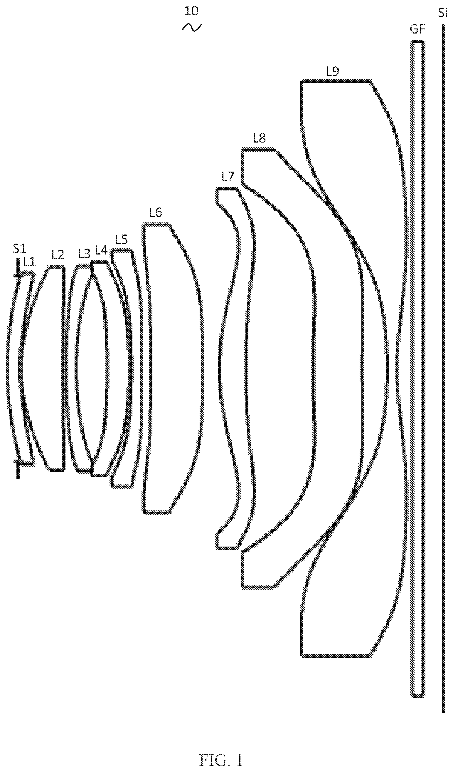
Referring to the accompanying drawings, the present disclosure provides a camera optical lens 10 . shows the camera optical lens 10 of the first embodiment of the present disclosure, and the camera optical lens 10 includes nine lenses. Specifically, the camera optical lens 10 includes, from an object side to an image side: an aperture S1, a first lens L 1 , a second lens L 2 , a third lens L 3 , a fourth lens L 4 , a fifth lens L 5 , a sixth lens L 6 , a seventh lens L 7 , an eighth lens L 8 and an ninth lens L 9 . An optical element, such as an optical filter GF, may be arranged between the ninth lens L 9 and an image surface S1.
In this embodiment, the first lens L 1 has a negative refractive power, the second lens L 2 has a positive refractive power, the third lens L 3 has a negative refractive power, the fourth lens L 4 has a positive refractive power, the fifth lens L 5 has a negative refractive power, the sixth lens L 6 has a negative refractive power, the seventh lens L 7 has a positive refractive power, the eighth lens L 8 has a positive refractive power, and the ninth lens L 9 has a negative refractive power. In this embodiment, the second lens L 2 has a positive refractive power, conducing to improve the performance of the optical system.
In this embodiment, the first lens L 1 , the second lens L 2 , the third lens L 3 , the fourth lens L 4 , the fifth lens L 5 , the sixth lens L 6 , the seventh lens L 7 , the eighth lens L 8 , and the ninth lens L 9 are all made of plastic material. In other embodiments, the lenses may also be made of other materials.
In this embodiment, a focal length of the camera optical lens 10 is defined as f, and a focal length of the first lens L 1 is defined as f1. The camera optical lens 10 satisfies a condition of −1.80≤f1/f≤−0.70, which specifies a ratio between the focal length f1 of the first lens L 1 and the focal length f of the camera optical lens 10 , effectively balancing spherical aberration and field curvature amount of the camera optical lens 10 in this range.
An on-axis thickness of the eighth lens L 8 is defined as d15, an on-axis distance from an image-side surface of the eighth lens L 8 to an object-side surface of the ninth lens L 9 is defined as d16, and the camera optical lens 10 further satisfies a condition of 2.00≤d15/d16≤12.00, which specifies a ratio between the on-axis thickness d15 of the eighth lens L 8 and an on-axis distance d16 from an image-side surface of the eighth lens L 8 to an object-side surface of the ninth lens L 9 , conducing to compress the total track length and achieve an ultra-thin effect in this range.
A central curvature radius of an object-side surface of the ninth lens L 9 is defined as R17, a central curvature radius of an image-side surface of the ninth lens L 9 is defined as R18 and the camera optical lens satisfies a condition of −3.50≤R17/R18≤−1.50, which specifies a shape of the ninth lens L 9 . Within this range, the deflection of light passing through the lens can be eased and aberrations can be effectively reduced.
In this embodiment, the object-side surface of the first lens L 1 is convex in a paraxial region, and the image-side surface of the first lens L 1 is concave in the paraxial region.
A central curvature radius of the object-side surface of the first lens L 1 is defined as R1, a central curvature radius of the image-side surface of the first lens L 1 is defined as R2, and the camera optical lens satisfies a condition of 0.56≤(R1+R2)/(R1−R2)≤5.43, which reasonably controls a shape of the first lens L 1 , so that the first lens L 1 can effectively correct system spherical aberration. Preferably, the camera optical lens 10 satisfies a condition of 0.90≤(R1+R2)/(R1−R2)≤4.35.
An on-axis thickness of the first lens L 1 is defined as d1, a total track length of the camera optical lens 10 is defined as TTL, and the camera optical lens 10 further satisfies a condition of 0.01≤d1/TTL≤0.06, conducing to realize an ultra-thin effect in this range. Preferably, the camera optical lens 10 further satisfies a condition of 0.01≤d1/TTL≤0.05.
In this embodiment, an object-side surface of the second lens L 2 is convex in the paraxial region, and an image-side surface of the second lens L 2 is concave in the paraxial region.
The focal length of the camera optical lens 10 is defined as f, a focal length of the second lens L 2 is defined as f2, and the camera optical lens 10 further satisfies a condition of 0.24≤f2/f≤0.91. In this way, a positive refractive power of the second lens L 2 is controlled within a reasonable range, so that it is beneficial to correct the aberration of the optical system. Preferably, the camera optical lens 10 further satisfies a condition of 0.39≤f2/f≤0.73.
A central curvature radius of the object-side surface of the second lens L 2 is defined as R3, a central curvature radius of the image-side surface of the second lens L 2 is defined as R4, and the camera optical lens 10 further satisfies a condition of −2.19≤(R3+R4)/(R3−R4)≤−0.48, which specifies a shape of the second lens L 2 . Within this range, a development towards ultra-thin and wide-angle lenses would facilitate correcting the problem of an on-axis aberration. Preferably, the camera optical lens 10 further satisfies a condition of −1.37≤(R3+R4)/(R3−R4)≤−0.60.
A total track length of the camera optical lens 10 is defined as TTL, an on-axis thickness of the second lens L 2 is defined as d3, and the camera optical lens 10 satisfies a condition of 0.03≤d3/TTL≤0.16. Within this range, it is beneficial to achieve ultra-thin lenses. Preferably, the camera optical lens 10 further satisfies a condition of 0.05≤d3/TTL≤0.13.
In an embodiment, an object-side surface of the third lens L 3 is convex in the paraxial region, and an image-side surface of the third lens L 3 is concave in the paraxial region.
The focal length of the camera optical lens 10 is defined as f, a focal length of the third lens L 3 is defined as f3, and the camera optical lens 10 further satisfies a condition of −5.98≤f3/f≤−1.44. In this way, a refractive power is distributed appropriately, so that the camera optical lens can attain a better imaging quality and a lower sensitivity. Preferably, the camera optical lens 10 further satisfies a condition of −3.74≤f3/f≤−1.80.
A central curvature radius of the object-side surface of the third lens L 3 is defined as R5, a central curvature radius of the image-side surface of the third lens L 3 is defined as R6, and the camera optical lens 10 further satisfies a condition of 1.43≤(R5+R6)/(R5−R6)≤5.57, which specifies a shape of the third lens L 3 . Within this range, the deflection of light passing through the lens can be eased and aberrations can be effectively reduced. Preferably, the camera optical lens 10 further satisfies a condition of 2.30≤(R5+R6)/(R5−R6)≤4.45.
The total track length of the camera optical lens 10 is defined as TTL, an on-axis thickness of the third lens L 3 is defined as d5, and the camera optical lens 10 further satisfies a condition of 0.01≤d5/TTL≤0.04. This can facilitate achieving ultra-thin lenses. Preferably, the camera optical lens 10 further satisfies a condition of 0.01≤d5/TTL≤0.03.
In an embodiment, an object-side surface of the fourth lens L 4 is concave in the paraxial region, and an image-side surface of the fourth lens L 4 is convex in the paraxial region.
The focal length of the camera optical lens 10 is defined as f, a focal length of the fourth lens L 4 is defined as f4, and the camera optical lens 10 further satisfies a condition of 1.06≤f4/f≤5.31. In this way, a refractive power is distributed appropriately, so that the camera optical lens can attain a better imaging quality and a lower sensitivity. Preferably, the camera optical lens 10 further satisfies a condition of 1.70≤f4/f≤4.25.
A central curvature radius of an object-side surface of the fourth lens L 4 is defined as R7, a central curvature radius of an image-side surface of the fourth lens L 4 is defined as R8, and the camera optical lens 10 further satisfies a condition of 0.05≤(R7+R8)/(R7−R8)≤3.87, which specifies a shape of the fourth lens L 4 . Within this range, a development towards ultra-thin and wide-angle lens would facilitate correcting problems such as an off-axis aberration. Preferably, the camera optical lens 10 further satisfies a condition of 0.08≤(R7+R8)/(R7−R8)≤3.09.
The total track length of the camera optical lens 10 is defined as TTL, an on-axis thickness of the fourth lens L 4 is defined as d7, and the camera optical lens 10 further satisfies a condition of 0.01≤d7/TTL≤0.08. Within this range, this can facilitate achieving ultra-thin lenses. Preferably, the camera optical lens 10 further satisfies a condition of 0.02≤d7/TTL≤0.06.
In an embodiment, an object-side surface of the fifth lens L 5 is concave in the paraxial region, and an image-side surface of the fifth lens L 5 is concave in the paraxial region.
The focal length of the camera optical lens 10 is defined as f, a focal length of the fifth lens L 5 is defined as f5, and the camera optical lens 10 further satisfies a condition of −5.01≤f5/f≤−0.97, which can effectively make a light angle of the camera optical lens 10 gentle and reduce a tolerance sensitivity. Preferably, the camera optical lens 10 further satisfies a condition of −3.13≤f5/f≤−1.22.
A central curvature radius of the object-side surface of the fifth lens L 5 is defined as R9, a central curvature radius of the image-side surface of the fifth lens L 5 is defined as R10, and the camera optical lens 10 further satisfies a condition of −0.43≤(R9+R10)/(R9−R10)≤0.31, which specifies a shape of the fifth lens L 5 . Within this range, a development towards ultra-thin and wide-angle lenses can facilitate correcting a problem of the off-axis aberration. Preferably, the camera optical lens 10 further satisfies a condition of −0.27≤(R9+R10)/(R9−R10)≤0.25.
The total track length of the camera optical lens 10 is defined as TTL, an on-axis thickness of the fifth lens L 5 is defined as d9, and the camera optical lens 10 further satisfies a condition of 0.01≤d9/TTL≤0.07. Within this range, this can facilitate achieving ultra-thin lenses. Preferably, the camera optical lens 10 further satisfies a condition of 0.02≤d9/TTL≤0.05.
In an embodiment, an object-side surface of the sixth lens L 6 is convex in the paraxial region, and an image-side surface of the sixth lens L 6 is concave in the paraxial region.
A focal length of the camera optical lens 10 is defined as f, a focal length of the sixth lens L 6 is defined as f6, and the camera optical lens satisfies a condition of −63.50≤f6/f≤−17.13. In this way, a refractive power is distributed appropriately, so that the system can attain a better imaging quality and a lower sensitivity. Preferably, the camera optical lens 10 further satisfies a condition of −39.69≤f6/f≤−21.42.
A central curvature radius of the object-side surface of the sixth lens L 6 is defined as R11, a central curvature radius of the image-side surface of the sixth lens L 6 is defined as R12, and the camera optical lens 10 further satisfies a condition of 1.59≤(R11+R12)/(R11−R12)≤11.32, which specifies a shape of the sixth lens L 6 . Within this range, a development towards ultra-thin and wide-angle lenses would facilitate correcting a problem like the off-axis aberration. Preferably, the camera optical lens 10 further satisfies a condition of 2.54≤(R11+R12)/(R11−R12)≤9.06.
The total track length of the camera optical lens 10 is defined as TTL, an on-axis thickness of the sixth lens L 6 is defined as d11, and the camera optical lens 10 further satisfies a condition of 0.05≤d11/TTL≤0.18. Within this range, this can facilitate achieving ultra-thin lenses. Preferably, the camera optical lens 10 further satisfies a condition of 0.08≤d11/TTL≤0.14.
In an embodiment, an object-side surface of the seventh lens L 7 is convex in the paraxial region, and an image-side surface of the seventh lens L 7 is concave in the paraxial region.
The focal length of the camera optical lens 10 is defined as f, a focal length of seventh lens L 7 is defined as f7, and the camera optical lens 10 further satisfies a condition of 0.48≤f7/f≤2.03. Within this range, a refractive power is distributed appropriately, so that the system can attain the better imaging quality and lower sensitivity. Preferably, the camera optical lens 10 further satisfies a condition of 0.76≤f7/f≤1.62.
A central curvature radius of the object-side surface of the seventh lens L 7 is defined as R13, a central curvature radius of the image-side surface of the seventh lens L 7 is defined as R14, and the camera optical lens 10 further satisfies a condition of −3.44≤(R13+R14)/(R13-R14)≤−0.96, which specifies a shape of the seventh lens L 7 . Within this specified range, the deflection of light passing through the lens can be eased and aberrations can be effectively reduced. Preferably, the camera optical lens 10 further satisfies a condition of −2.15≤(R13+R14)/(R13-R14)≤−1.20.
The total track length of the camera optical lens 10 is defined as TTL, an on-axis thickness of the seventh lens L 7 is defined as d13, and the camera optical lens 10 further satisfies a condition of 0.02≤d13/TTL≤0.09. Within this range, it is beneficial to achieve ultra-thin lenses. Preferably, the camera optical lens 10 further satisfies a condition of 0.04≤d13/TTL≤0.07.
In an embodiment, an object-side surface of the eighth lens L 8 is convex in the paraxial region, and an image-side surface of eighth lens L 8 is concave in the paraxial region.
The focal length of the camera optical lens 10 is defined as f, a focal length of eighth lens L 8 is defined as f8, and the camera optical lens 10 further satisfies a condition of 0.46≤f8/f≤7.90. In this way, a refractive power is distributed appropriately, so that the camera optical lens can attain a better imaging quality and a lower sensitivity. Preferably, the camera optical lens 10 further satisfies a condition of 0.74≤f8/f≤6.32.
A central curvature radius of the object-side surface of the eighth lens L 8 is defined as R15, a central curvature radius of the image-side surface of the sixth lens L 8 is defined as R16, and the camera optical lens 10 further satisfies a condition of −6.50≤(R15+R16)/(R15-R16)≤−0.31, which specifies a shape of the eighth lens L 8 . Within this range, a development towards ultra-thin and wide-angle lenses would facilitate correcting a problem like the off-axis aberration. Preferably, the camera optical lens 10 further satisfies a condition of −4.06≤(R15+R16)/(R15-R16)≤−0.39.
The total track length of the camera optical lens 10 is defined as TTL, an on-axis thickness of the eighth lens L 8 is defined as d15, and the camera optical lens 10 further satisfies a condition of 0.06≤d15/TTL≤0.23. Within this range, this can facilitate achieving ultra-thin lenses. Preferably, the camera optical lens 10 further satisfies a condition of 0.09≤d15/TTL≤0.18.
In an embodiment, an object-side surface of the ninth lens L 9 is concave in the paraxial region, and an image-side surface of ninth lens L 9 is concave in the paraxial region.
The focal length of the camera optical lens 10 is defined as f, a focal length of the ninth lens L 9 is defined as f9, and the camera optical lens 10 further satisfies a condition of −1.60≤f9/f≤−0.34. In this way, a refractive power is distributed appropriately, so that the camera optical lens can attain a better imaging quality and a lower sensitivity. Preferably, the camera optical lens 10 further satisfies a condition of −1.00≤f9/f≤−0.43.
A central curvature radius of the object-side surface of the ninth lens L 9 is defined as R17, a central curvature radius of the image-side surface of the ninth lens L 9 is defined as R18, and the camera optical lens 10 further satisfies a condition of 0.11≤(R17+R18)/(R17-R18)≤0.77, which specifies a shape of the ninth lens L 9 . Within this range, a development towards ultra-thin and wide-angle lenses would facilitate correcting a problem like the off-axis aberration. Preferably, the camera optical lens 10 further satisfies a condition of 0.17≤(R17+R18)/(R17-R18)≤0.62.
The total track length of the camera optical lens 10 is defined as TTL, an on-axis thickness of the ninth lens L 9 is defined as d17, and the camera optical lens 10 further satisfies a condition of 0.01≤d17/TTL≤0.08. Within this range, this can facilitate achieving ultra-thin lenses. Preferably, the camera optical lens 10 further satisfies a condition of 0.02≤d17/TTL≤0.06.
In an embodiment, an image height of the camera optical lens 10 is defined as IH, the total track length of the camera optical lens 10 is defined as TTL, and the camera optical lens 10 further satisfies a condition of TTL/IH≤1.62, thus facilitating to achieve ultra-thin lenses.
In an embodiment, an FOV (field of view) of the camera optical lens 10 is greater than or equal to 81.00°, thereby achieving a wide-angle and a better imaging performance of the camera optical lens 10 .
It can be understood that, in other embodiments, for the first lens L 1 , the second lens L 2 , the third lens L 3 , the fourth lens L 4 , the fifth lens L 5 , the sixth lens L 6 , the seventh lens L 7 , the eighth lens L 8 , and the ninth lens L 9 , surface profiles of an object-side surface and an image-side surface respectively may be configured in other convex or concave arrangement.
When the above condition is satisfied, the camera optical lens 10 can meet the design requirements of wide-angle and ultra-thin in the case that a good optical performance is maintained. According to characteristics of the camera optical lens 10 , the camera optical lens 10 is particularly suitable for mobile phone camera lens components and WEB camera lenses composed of camera elements such as CCD and CMOS with high pixel.
In the following, examples will be used to describe the camera optical lens 10 of the present disclosure. The symbols recorded in each example will be described as follows. The focal length, on-axis distance, central curvature radius, on-axis thickness, inflexion point position, and arrest point position are all in units of mm.
TTL refers to a total track length (an on-axis distance from an object-side surface of the first lens L 1 to an image surface S1) in units of mm.
Aperture value FNO refers to a ratio of an effective focal length of the camera optical lens to an entrance pupil diameter.
Preferably, inflexion points and/or arrest points can be arranged on the object-side surface and/or the image-side surface of the lens, so as to satisfy the demand for high quality imaging. The description below may be referred for specific implementations.
The design data of the camera optical lens 10 in the first embodiment of the present disclosure are shown in Table 1 and Table 2.
TABLE 1
R d nd vd
S1 ∞ d0= −0.219
R1 4.646 d1= 0.243 nd1 1.5444 v1 55.82
R2 2.636 d2= 0.028
R3 2.074 d3= 0.826 nd2 1.5444 v2 55.82
R4 45.192 d4= 0.069
R5 8.618 d5= 0.200 nd3 1.6359 v3 23.82
R6 4.364 d6= 0.613
R7 −16.188 d7= 0.442 nd4 1.5444 v4 55.82
R8 −7.141 d8= 0.040
R9 −16.636 d9= 0.204 nd5 1.6153 v5 25.94
R10 25.787 d10= 0.174
R11 83.149 d11= 1.029 nd6 1.5444 v6 55.82
R12 43.293 d12= 0.338
R13 3.464 d13= 0.531 nd7 1.5346 v7 55.69
R14 17.751 d14= 1.323
R15 9.543 d15= 0.981 nd8 1.5661 v8 37.71
R16 18.035 d16= 0.490
R17 −7.297 d17= 0.200 nd9 1.5450 v9 55.81
R18 4.685 d18= 0.104
R19 ∞ d19= 0.210 ndg 1.5168 vg 64.17
R20 ∞ d20= 0.610
In the table, meanings of various symbols will be described as follows:
•
• S1: aperture; • R: curvature radius at a center of an optical surface; • R1: central curvature radius of the object-side surface of the first lens L 1 ; • R2: central curvature radius of the image-side surface of the first lens L 1 ; • R3: central curvature radius of the object-side surface of the second lens L 2 ; • R4: central curvature radius of the image-side surface of the second lens L 2 ; • R5: central curvature radius of the object-side surface of the third lens L 3 ; • R6: central curvature radius of the image-side surface of the third lens L 3 ; • R7: central curvature radius of the object-side surface of the fourth lens L 4 ; • R8: central curvature radius of the image-side surface of the fourth lens L 4 ; • R9: central curvature radius of the object-side surface of the fifth lens L 5 ; • R10: central curvature radius of the image-side surface of the fifth lens L 5 ; • R11: central curvature radius of the object-side surface of the sixth lens L 6 ; • R12: central curvature radius of the image-side surface of the sixth lens L 6 ; • R13: central curvature radius of the object-side surface of the seventh lens L 7 ; • R14: central curvature radius of the image-side surface of the seventh lens L 7 ; • R15: central curvature radius of the object-side surface of the eighth lens L 8 ; • R16: central curvature radius of the image-side surface of the eighth lens L 8 ; • R17: central curvature radius of the object-side surface of the ninth lens L 9 ; • R18: central curvature radius of the image-side surface of the ninth lens L 9 ; • R19: central curvature radius of an object-side surface of the optical filter GF; • R20: central curvature radius of an image-side surface of the optical filter GF; • d: on-axis thickness of a lens, or an on-axis distance between lenses; • d0: on-axis distance from the aperture S1 to the object-side surface of the first lens L 1 ; • d1: on-axis thickness of the first lens L 1 ; • d2: on-axis distance from the image-side surface of the first lens L 1 to the object-side surface of the second lens L 2 ; • d3: on-axis thickness of the second lens L 2 ; • d4: on-axis distance from the image-side surface of the second lens L 2 to the object-side surface of the third lens L 3 ; • d5: on-axis thickness of the third lens L 3 ; • d6: on-axis distance from the image-side surface of the third lens L 3 to the object-side surface of the fourth lens L 4 ; • d7: on-axis thickness of the fourth lens L 4 ; • d8: on-axis distance from the image-side surface of the fourth lens L 4 to the object-side surface of the fifth lens L 5 ; • d9: on-axis thickness of the fifth lens L 5 ; • d10: on-axis distance from the image-side surface of the fifth lens L 5 to the object-side surface of the sixth lens L 6 ; • d11: on-axis thickness of the sixth lens L 6 ; • d12: on-axis distance from the image-side surface of the sixth lens L 6 to the object-side surface of the seventh lens L 7 ; • d13: on-axis thickness of the seventh lens L 7 ; • d14: on-axis distance from the image-side surface of the seventh lens L 7 to the object-side surface of the eighth lens L 8 ; • d15: on-axis thickness of the seventh lens L 8 ; • d16: on-axis distance from the image-side surface of the eighth lens L 8 to the object-side surface of the ninth lens L 9 ; • d17: on-axis thickness of the ninth lens L 9 ; • d18: on-axis distance from the image-side surface of the ninth lens L 9 to the object-side surface of the optical filter GF; • d19: on-axis thickness of the optical filter GF; • d20: on-axis distance from the image-side surface of the optical filter GF to the image surface S1; • nd: refractive index of a d line; • nd1: refractive index of the d line of the first lens L 1 ; • nd2: refractive index of the d line of the second lens L 2 ; • nd3: refractive index of the d line of the third lens L 3 ; • nd4: refractive index of the d line of the fourth lens L 4 ; • nd5: refractive index of the d line of the fifth lens L 5 ; • nd6: refractive index of the d line of the sixth lens L 6 ; • nd7: refractive index of the d line of the seventh lens L 7 ; • nd8: refractive index of the d line of the eighth lens L 8 ; • nd9: refractive index of the d line of the ninth lens L 9 ; • ndg: refractive index of the d line of the optical filter GF; • vd: abbe number; • v1: abbe number of the first lens L 1 ; • v2: abbe number of the second lens L 2 ; • v3: abbe number of the third lens L 3 ; • v4: abbe number of the fourth lens L 4 ; • v5: abbe number of the fifth lens L 5 ; • v6: abbe number of the sixth lens L 6 ; • v7: abbe number of the seventh lens L 7 ; • v8: abbe number of the eighth lens L 8 ; • v9: abbe number of the ninth lens L 9 ; • vg: abbe number of the optical filter GF.
Table 2 shows aspherical surface data of the camera optical lens 10 in the first embodiment of the present disclosure.
TABLE 2
Conic
coefficient Aspheric surface coefficients
k A4 A6 A8 A10 A12
R1 −1.3966E+00 −9.3096E−03 9.2321E−03 −7.8166E−03 4.0479E−03 −9.9530E−04
R2 −4.5429E+00 −1.0030E−01 1.4298E−01 −1.6290E−01 1.3919E−01 −8.4281E−02
R3 3.0481E−01 −1.2437E−01 1.3510E−01 −1.5540E−01 1.3514E−01 −8.5137E−02
R4 −3.3873E+02 9.0115E−03 −8.6152E−03 9.1337E−03 −1.0615E−02 8.6508E−03
R5 −7.7036E+01 2.2796E−03 −5.3514E−03 1.2298E−02 −1.1791E−02 7.8187E−03
R6 3.0216E+00 −2.5294E−02 1.2327E−02 −2.5268E−03 −1.5536E−03 2.3347E−03
R7 8.1094E+01 −1.7684E−02 3.5366E−03 −1.3541E−02 1.6279E−02 −1.3557E−02
R8 1.2961E+01 −1.9686E−02 1.5475E−02 −2.7923E−02 2.8859E−02 −2.0011E−02
R9 7.1118E+01 −2.9184E−02 7.6391E−03 −9.7531E−03 1.1877E−02 −9.4153E−03
R10 −7.5234E+01 −2.4570E−02 −5.9422E−03 1.1523E−02 −9.0071E−03 4.3613E−03
R11 2.0000E+02 −1.5549E−02 −2.2914E−04 2.8538E−03 −2.2171E−03 9.4445E−04
R12 9.9000E+01 −4.1222E−02 8.9755E−03 −2.4090E−03 6.1263E−04 −1.2983E−04
R13 −2.1271E+00 −1.2167E−02 3.6721E−03 −1.3867E−03 2.6293E−04 −5.9498E−05
R14 −1.2645E+02 1.2567E−02 −1.4633E−03 2.3209E−04 −3.8603E−04 1.4020E−04
R15 −3.4788E+00 −1.8564E−02 −1.3611E−03 5.0378E−04 −5.1917E−05 −4.9801E−06
R16 −5.0801E+00 −8.4650E−03 −4.2939E−03 1.3451E−03 −2.4514E−04 2.8179E−05
R17 −3.6481E+00 −2.3655E−02 2.4541E−03 −9.9854E−05 3.2131E−06 −1.4030E−07
R18 −1.6413E+00 −2.4412E−02 3.2201E−03 −2.6104E−04 1.3328E−05 −4.1545E−07
Conic
coefficient Aspheric surface coefficients
k A14 A16 A18 A20
R1 −1.3966E+00 −8.2513E−05 1.2748E−04 −3.2820E−05 2.9520E−06
R2 −4.5429E+00 3.4731E−02 −9.2005E−03 1.4064E−03 −9.3966E−05
R3 3.0481E−01 3.6720E−02 −1.0255E−02 1.6645E−03 −1.1985E−04
R4 −3.3873E+02 −4.4535E−03 1.4055E−03 −2.5379E−04 2.0255E−05
R5 −7.7036E+01 −3.3192E−03 8.5775E−04 −1.2553E−04 8.1914E−06
R6 3.0216E+00 −1.4211E−03 4.9003E−04 −9.2315E−05 7.3432E−06
R7 8.1094E+01 7.6177E−03 −2.6657E−03 5.2874E−04 −4.4957E−05
R8 1.2961E+01 9.5338E−03 −2.9161E−03 5.0875E−04 −3.7809E−05
R9 7.1118E+01 4.8882E−03 −1.5773E−03 2.8015E−04 −2.0517E−05
R10 −7.5234E+01 −1.3141E−03 2.3706E−04 −2.3099E−05 9.3083E−07
R11 2.0000E+02 −2.2705E−04 3.1376E−05 −2.3573E−06 7.5368E−08
R12 9.9000E+01 1.8918E−05 −1.6053E−06 7.6629E−08 −1.8626E−09
R13 −2.1271E+00 1.4740E−05 −2.3678E−06 1.9323E−07 −6.0886E−09
R14 −1.2645E+02 −2.4395E−05 2.3054E−06 −1.1345E−07 2.2769E−09
R15 −3.4788E+00 1.2280E−06 −2.5444E−08 −6.5673E−09 3.3689E−10
R16 −5.0801E+00 −2.0106E−06 8.8127E−08 −2.2343E−09 2.5718E−11
R17 −3.6481E+00 2.7723E−10 3.6163E−10 −1.4625E−11 1.7727E−13
R18 −1.6413E+00 5.4153E−09 8.9599E−11 −3.8415E−12 3.4379E−14
Here, K is a conic coefficient, and A4, A6, A8, A10, A12, A14, A16, A18 and A20 are aspheric surface coefficients. y =( x 2 /R )/{1+[1−( k+ 1)( x 2 /R 2 )] 1/2 }+A 4 x 4 +A 6 x 6 +A 8 x 8 +A 10 x 10 +A 12 x 12 +A 14 x 14 +A 16 x 16 +A 18 x 18 +A 20 x 20 (1)
Here, x denotes a vertical distance between a point on an aspheric curve and an optical axis, and y denotes a depth of a aspheric surface (i.e. a vertical distance between a point on an aspheric surface that is x away from the optical axis, and a tangent plane tangent to an vertex of the optical axis on the aspheric surface).
For convenience, an aspheric surface of each lens surface uses the aspheric surfaces shown in the above formula (1). However, the present disclosure is not limited to the aspherical polynomials form shown in the formula (1).
Table 3 and Table 4 show design data of inflexion points and arrest points of the camera optical lens 10 according to the first embodiment of the present disclosure. P1R1 and P1R2 respectively represent the object-side surface and the image-side surface of the first lens L 1 , P2R1 and P2R2 respectively represent the object-side surface and the image-side surface of the second lens L 2 , P3R1 and P3R2 respectively represent the object-side surface and the image-side surface of the third lens L 3 , P4R1 and P4R2 respectively represent the object-side surface and the image-side surface of the fourth lens L 4 , P5R1 and P5R2 respectively represent the object-side surface and the image-side surface of the fifth lens L 5 , P6R1 and P6R2 respectively represent the object-side surface and the image-side surface of the sixth lens L 6 , P7R1 and P7R2 respectively represent the object-side surface and the image-side surface of the seventh lens L 7 . P8R1 and P8R2 respectively represent the object-side surface and the image-side surface of the eighth lens L 8 , P9R1 and P9R2 respectively represent the object-side surface and the image-side surface of the ninth lens L 9 . The data in the column named “inflexion point position” refer to vertical distances from inflexion points arranged on each lens surface to the optic axis of the camera optical lens 10 . The data in the column named “arrest point position” refer to vertical distances from arrest points arranged on each lens surface to the optical axis of the camera optical lens 10 .
TABLE 3
Number(s)
of Inflexion Inflexion Inflexion
inflexion point point point
points position 1 position 2 position 3
P1R1 0 / / /
P1R2 0 / / /
P2R1 0 / / /
P2R2 2 1.195 1.695 /
P3R1 0 / / /
P3R2 0 / / /
P4R1 0 / / /
P4R2 2 1.625 1.795 /
P5R1 2 1.755 1.855 /
P5R2 2 0.355 1.805 /
P6R1 2 0.255 1.725 /
P6R2 2 0.225 2.295 /
P7R1 1 1.405 / /
P7R2 2 1.555 3.075 /
P8R1 2 0.665 3.225 /
P8R2 2 0.625 3.305 /
P9R1 2 2.585 4.735 /
P9R2 3 0.985 4.895 5.135
TABLE 4
Number(s) of Arrest point Arrest point
arrest points position 1 position 2
P1R1 0 / /
P1R2 0 / /
P2R1 0 / /
P2R2 1 1.565 /
P3R1 0 / /
P3R2 0 / /
P4R1 0 / /
P4R2 0 / /
P5R1 0 / /
P5R2 1 0.605 /
P6R1 2 0.445 2.225
P6R2 1 0.385 /
P7R1 1 2.145 /
P7R2 1 2.145 /
P8R1 1 1.135 /
P8R2 1 1.035 /
P9R1 2 4.625 4.835
P9R2 1 2.285 /
and illustrate a longitudinal aberration and a lateral color of light with wavelengths of 656 nm, 587 nm, 546 nm, 486 nm and 436 nm after passing the camera optical lens 10 according to the first embodiment, respectively. illustrates a field curvature and a distortion of light with a wavelength of 546 nm after passing the camera optical lens 10 according to the first embodiment. In , a field curvature S is a field curvature in a sagittal direction, and T is a field curvature in a meridional direction.
Table 13 in the following shows various values of first, second and third embodiments and values corresponding to parameters which are specified in the above conditions.
As shown in Table 13, the first embodiment satisfies the above conditions.
In this Embodiment, an entrance pupil diameter (ENPD) of the camera optical lens is 3.243 mm, an image height (IH) of 1.0H is 6.000 mm, a field of view (FOV) in a diagonal direction is 85.11°. Thus, the camera optical lens meets the design requirements of wide-angle and ultra-thin. Its on-axis and off-axis aberrations are fully corrected, thereby achieving excellent optical characteristics.
Second Embodiment
shows a camera optical lens 20 of the second embodiment of the present disclosure, the second embodiment is basically the same as the first embodiment and involves symbols having the same meanings as the first embodiment, and only differences therebetween will be described in the following.
The image-side of the eighth lens L 8 in the paraxial region is convex.
Table 5 and Table 6 show design data of the camera optical lens 20 in the second embodiment of the present disclosure.
TABLE 5
R d nd vd
S1 ∞ d0= −0.140
R1 6.761 d1= 0.338 nd1 1.5444 v1 55.82
R2 2.939 d2= 0.028
R3 2.078 d3= 0.950 nd2 1.5444 v2 55.82
R4 173.123 d4= 0.166
R5 9.853 d5= 0.250 nd3 1.6359 v3 23.82
R6 4.761 d6= 0.479
R7 −57.786 d7= 0.365 nd4 1.5444 v4 55.82
R8 −8.603 d8= 0.047
R9 −15.703 d9= 0.213 nd5 1.6153 v5 25.94
R10 11.630 d10= 0.025
R11 32.498 d11= 1.000 nd6 1.5444 v6 55.82
R12 24.896 d12= 0.283
R13 3.485 d13= 0.419 nd7 1.5346 v7 55.69
R14 13.179 d14= 0.979
R15 4.357 d15= 1.338 nd8 1.5661 v8 37.71
R16 −13.754 d16= 0.114
R17 −8.763 d17= 0.247 nd9 1.5450 v9 55.81
R18 2.818 d18= 0.682
R19 ∞ d19= 0.210 ndg 1.5168 vg 64.17
R20 ∞ d20= 0.771
Table 6 shows aspherical surface data of each lens of the camera optical lens 20 in the second embodiment of the present disclosure.
TABLE 6
Conic
coefficient Aspheric surface coefficients
k A4 A6 A8 A10 A12
R1 −1.3966E+00 −9.3096E−03 9.2321E−03 −7.8166E−03 4.0479E−03 −9.9530E−04
R2 −4.5429E+00 −1.0030E−01 1.4298E−01 −1.6290E−01 1.3919E−01 −8.4281E−02
R3 3.0481E−01 −1.2437E−01 1.3510E−01 −1.5540E−01 1.3514E−01 −8.5137E−02
R4 −3.3873E+02 9.0115E−03 −8.6152E−03 9.1337E−03 −1.0615E−02 8.6508E−03
R5 −7.7036E+01 2.2796E−03 −5.3514E−03 1.2298E−02 −1.1791E−02 7.8187E−03
R6 3.0216E+00 −2.5294E−02 1.2327E−02 −2.5268E−03 −1.5536E−03 2.3347E−03
R7 8.1094E+01 −1.7684E−02 3.5366E−03 −1.3541E−02 1.6279E−02 −1.3557E−02
R8 1.2961E+01 −1.9686E−02 1.5475E−02 −2.7923E−02 2.8859E−02 −2.0011E−02
R9 7.1118E+01 −2.9184E−02 7.6391E−03 −9.7531E−03 1.1877E−02 −9.4153E−03
R10 −7.5234E+01 −2.4570E−02 −5.9422E−03 1.1523E−02 −9.0071E−03 4.3613E−03
R11 2.0000E+02 −1.5549E−02 −2.2914E−04 2.8538E−03 −2.2171E−03 9.4445E−04
R12 9.9000E+01 −4.1222E−02 8.9755E−03 −2.4090E−03 6.1263E−04 −1.2983E−04
R13 −2.1271E+00 −1.2167E−02 3.6721E−03 −1.3867E−03 2.6293E−04 −5.9498E−05
R14 −1.2645E+02 1.2567E−02 −1.4633E−03 2.3209E−04 −3.8603E−04 1.4020E−04
R15 −3.4788E+00 −1.8564E−02 −1.3611E−03 5.0378E−04 −5.1917E−05 −4.9801E−06
R16 −5.0801E+00 −8.4650E−03 −4.2939E−03 1.3451E−03 −2.4514E−04 2.8179E−05
R17 −3.6481E+00 −2.3655E−02 2.4541E−03 −9.9854E−05 3.2131E−06 −1.4030E−07
R18 −1.6413E+00 −2.4412E−02 3.2201E−03 −2.6104E−04 1.3328E−05 −4.1545E−07
Conic
coefficient Aspheric surface coefficients
k A14 A16 A18 A20
R1 −1.3966E+00 −8.2513E−05 1.2748E−04 −3.2820E−05 2.9520E−06
R2 −4.5429E+00 3.4731E−02 −9.2005E−03 1.4064E−03 −9.3966E−05
R3 3.0481E−01 3.6720E−02 −1.0255E−02 1.6645E−03 −1.1985E−04
R4 −3.3873E+02 −4.4535E−03 1.4055E−03 −2.5379E−04 2.0255E−05
R5 −7.7036E+01 −3.3192E−03 8.5775E−04 −1.2553E−04 8.1914E−06
R6 3.0216E+00 −1.4211E−03 4.9003E−04 −9.2315E−05 7.3432E−06
R7 8.1094E+01 7.6177E−03 −2.6657E−03 5.2874E−04 −4.4957E−05
R8 1.2961E+01 9.5338E−03 −2.9161E−03 5.0875E−04 −3.7809E−05
R9 7.1118E+01 4.8882E−03 −1.5773E−03 2.8015E−04 −2.0517E−05
R10 −7.5234E+01 −1.3141E−03 2.3706E−04 −2.3099E−05 9.3083E−07
R11 2.0000E+02 −2.2705E−04 3.1376E−05 −2.3573E−06 7.5368E−08
R12 9.9000E+01 1.8918E−05 −1.6053E−06 7.6629E−08 −1.8626E−09
R13 −2.1271E+00 1.4740E−05 −2.3678E−06 1.9323E−07 −6.0886E−09
R14 −1.2645E+02 −2.4395E−05 2.3054E−06 −1.1345E−07 2.2769E−09
R15 −3.4788E+00 1.2280E−06 −2.5444E−08 −6.5673E−09 3.3689E−10
R16 −5.0801E+00 −2.0106E−06 8.8127E−08 −2.2343E−09 2.5718E−11
R17 −3.6481E+00 2.7723E−10 3.6163E−10 −1.4625E−11 1.7727E−13
R18 −1.6413E+00 5.4153E−09 8.9599E−11 −3.8415E−12 3.4379E−14
Table 7 and table 8 show design data of inflexion points and arrest points of each lens of the camera optical lens 20 lens according to the second embodiment of the present disclosure.
TABLE 7
Number(s) Inflexion Inflexion Inflexion
of inflexion point point point
points position 1 position 2 position 3
P1R1 0 / / /
P1R2 0 / / /
P2R1 0 / / /
P2R2 2 1.115 1.695 /
P3R1 0 / / /
P3R2 0 / / /
P4R1 1 1.525 / /
P4R2 1 1.545 / /
P5R1 0 / / /
P5R2 2 0.485 1.805 /
P6R1 2 0.425 1.635 /
P6R2 2 0.295 2.185 /
P7R1 1 1.405 / /
P7R2 2 1.545 3.075 /
P8R1 2 0.915 3.225 /
P8R2 1 3.385 / /
P9R1 1 2.575 / /
P9R2 3 1.355 4.915 5.115
TABLE 8
Number of Arrest point Arrest point
arrest points position 1 position 2
P1R1 0 / /
P1R2 0 / /
P2R1 0 / /
P2R2 1 1.475 /
P3R1 0 / /
P3R2 0 / /
P4R1 0 / /
P4R2 0 / /
P5R1 0 / /
P5R2 1 0.855 /
P6R1 2 0.745 1.995
P6R2 1 0.525 /
P7R1 1 2.145 /
P7R2 1 2.165 /
P8R1 1 1.595 /
P8R2 0 / /
P9R1 0 / /
P9R2 1 3.795 /
and illustrate a longitudinal aberration and a lateral color of light with wavelengths of 656 nm, 587 nm, 546 nm, 486 nm and 436 nm after passing the camera optical lens 20 according to the second embodiment. illustrates a field curvature and a distortion of light with a wavelength of 546 nm after passing the camera optical lens 20 according to the second embodiment. A field curvature S in is a field curvature in a sagittal direction, and T is a field curvature in a meridian direction.
As shown in Table 13, the second embodiment satisfies the above conditions.
In this embodiment, an entrance pupil diameter (ENPD) of the camera optical lens 20 is 3.215 mm, an image height (IH) of 1.0H is 6.000 mm, and a field of view (FOV) in a diagonal direction is 85.30°. Thus, the camera optical lens 20 meets the design requirements of wide-angle and ultra-thin. Its on-axis and off-axis aberrations are fully corrected, thereby achieving excellent optical characteristics.
Third Embodiment
shows a camera optical lens 30 of the third embodiment of the present disclosure, the third embodiment is basically the same as the first embodiment and involves symbols having the same meanings as the first embodiment, and only differences therebetween will be described in the following.
The image-side surface of the second lens L 2 is convex in the paraxial region, the object-side surface of the fourth lens L 4 is convex in the paraxial region, and the image-side surface of the eighth lens L 8 is convex in the paraxial region.
Table 9 and Table 10 show design data of the camera optical lens 30 in the embodiment of the present disclosure.
TABLE 9
R d nd vd
S1 ∞ d0= −0.006
R1 43.337 d1= 0.175 nd1 1.5444 v1 55.82
R2 2.588 d2= 0.023
R3 2.088 d3= 0.645 nd2 1.5444 v2 55.82
R4 −13.066 d4= 0.676
R5 9.632 d5= 0.146 nd3 1.6359 v3 23.82
R6 5.543 d6= 0.299
R7 17.713 d7= 0.225 nd4 1.5444 v4 55.82
R8 −14.498 d8= 0.144
R9 −15.863 d9= 0.444 nd5 1.6153 v5 25.94
R10 10.414 d10= 0.244
R11 36.517 d11= 0.937 nd6 1.5444 v6 55.82
R12 26.983 d12= 0.313
R13 2.930 d13= 0.438 nd7 1.5346 v7 55.69
R14 16.183 d14= 1.393
R15 5.531 d15= 1.080 nd8 1.5661 v8 37.71
R16 −15.057 d16= 0.270
R17 −5.360 d17= 0.487 nd9 1.5450 v9 55.81
R18 3.146 d18= 0.710
R19 ∞ d19= 0.210 ndg 1.5168 vg 64.17
R20 ∞ d20= 0.835
Table 10 shows aspherical surface data of each lens of the camera optical lens 30 in the third embodiment of the present disclosure.
TABLE 10
Conic
coefficient Aspheric surface coefficients
k A4 A6 A8 A10 A12
R1 −1.3966E+00 −9.3096E−03 9.2321E−03 −7.8166E−03 4.0479E−03 −9.9530E−04
R2 −4.5429E+00 −1.0030E−01 1.4298E−01 −1.6290E−01 1.3919E−01 −8.4281E−02
R3 3.0481E−01 −1.2437E−01 1.3510E−01 −1.5540E−01 1.3514E−01 −8.5137E−02
R4 −3.3873E+02 9.0115E−03 −8.6152E−03 9.1337E−03 −1.0615E−02 8.6508E−03
R5 −7.7036E+01 2.2796E−03 −5.3514E−03 1.2298E−02 −1.1791E−02 7.8187E−03
R6 3.0216E+00 −2.5294E−02 1.2327E−02 −2.5268E−03 −1.5536E−03 2.3347E−03
R7 8.1094E+01 −1.7684E−02 3.5366E−03 −1.3541E−02 1.6279E−02 −1.3557E−02
R8 1.2961E+01 −1.9686E−02 1.5475E−02 −2.7923E−02 2.8859E−02 −2.0011E−02
R9 7.1118E+01 −2.9184E−02 7.6391E−03 −9.7531E−03 1.1877E−02 −9.4153E−03
R10 −7.5234E+01 −2.4570E−02 −5.9422E−03 1.1523E−02 −9.0071E−03 4.3613E−03
R11 2.0000E+02 −1.5549E−02 −2.2914E−04 2.8538E−03 −2.2171E−03 9.4445E−04
R12 9.9000E+01 −4.1222E−02 8.9755E−03 −2.4090E−03 6.1263E−04 −1.2983E−04
R13 −2.1271E+00 −1.2167E−02 3.6721E−03 −1.3867E−03 2.6293E−04 −5.9498E−05
R14 −1.2645E+02 1.2567E−02 −1.4633E−03 2.3209E−04 −3.8603E−04 1.4020E−04
R15 −3.4788E+00 −1.8564E−02 −1.3611E−03 5.0378E−04 −5.1917E−05 −4.9801E−06
R16 −5.0801E+00 −8.4650E−03 −4.2939E−03 1.3451E−03 −2.4514E−04 2.8179E−05
R17 −3.6481E+00 −2.3655E−02 2.4541E−03 −9.9854E−05 3.2131E−06 −1.4030E−07
R18 −1.6413E+00 −2.4412E−02 3.2201E−03 −2.6104E−04 1.3328E−05 −4.1545E−07
Conic
coefficient Aspheric surface coefficients
k A14 A16 A18 A20
R1 −1.3966E+00 −8.2513E−05 1.2748E−04 −3.2820E−05 2.9520E−06
R2 −4.5429E+00 3.4731E−02 −9.2005E−03 1.4064E−03 −9.3966E−05
R3 3.0481E−01 3.6720E−02 −1.0255E−02 1.6645E−03 −1.1985E−04
R4 −3.3873E+02 −4.4535E−03 1.4055E−03 −2.5379E−04 2.0255E−05
R5 −7.7036E+01 −3.3192E−03 8.5775E−04 −1.2553E−04 8.1914E−06
R6 3.0216E+00 −1.4211E−03 4.9003E−04 −9.2315E−05 7.3432E−06
R7 8.1094E+01 7.6177E−03 −2.6657E−03 5.2874E−04 −4.4957E−05
R8 1.2961E+01 9.5338E−03 −2.9161E−03 5.0875E−04 −3.7809E−05
R9 7.1118E+01 4.8882E−03 −1.5773E−03 2.8015E−04 −2.0517E−05
R10 −7.5234E+01 −1.3141E−03 2.3706E−04 −2.3099E−05 9.3083E−07
R11 2.0000E+02 −2.2705E−04 3.1376E−05 −2.3573E−06 7.5368E−08
R12 9.9000E+01 1.8918E−05 −1.6053E−06 7.6629E−08 −1.8626E−09
R13 −2.1271E+00 1.4740E−05 −2.3678E−06 1.9323E−07 −6.0886E−09
R14 −1.2645E+02 −2.4395E−05 2.3054E−06 −1.1345E−07 2.2769E−09
R15 −3.4788E+00 1.2280E−06 −2.5444E−08 −6.5673E−09 3.3689E−10
R16 −5.0801E+00 −2.0106E−06 8.8127E−08 −2.2343E−09 2.5718E−11
R17 −3.6481E+00 2.7723E−10 3.6163E−10 −1.4625E−11 1.7727E−13
R18 −1.6413E+00 5.4153E−09 8.9599E−11 −3.8415E−12 3.4379E−14
Table 11 and Table 12 show design data inflexion points and arrest points of the respective lenses in the camera optical lens 30 according to the third embodiment of the present disclosure.
TABLE 11
Number(s) Inflexion Inflexion
of inflexion point point
points position 1 position 2
P1R1 1 0.725 /
P1R2 0 / /
P2R1 1 1.565 /
P2R2 1 1.695 /
P3R1 0 / /
P3R2 0 / /
P4R1 2 0.545 1.475
P4R2 1 1.505 /
P5R1 0 / /
P5R2 2 0.505 1.805
P6R1 2 0.395 1.665
P6R2 2 0.285 2.245
P7R1 1 1.435 /
P7R2 2 1.555 3.075
P8R1 2 0.835 3.225
P8R2 1 3.385 /
P9R1 1 2.585 /
P9R2 2 1.275 4.915
TABLE 12
Number of Arrest point Arrest point
arrest points position 1 position 2
P1R1 0 / /
P1R2 0 / /
P2R1 0 / /
P2R2 0 / /
P3R1 0 / /
P3R2 0 / /
P4R1 2 0.885 1.675
P4R2 0 / /
P5R1 0 / /
P5R2 1 0.885 /
P6R1 2 0.695 2.075
P6R2 1 0.495 /
P7R1 1 2.205 /
P7R2 1 2.155 /
P8R1 1 1.455 /
P8R2 0 / /
P9R1 0 / /
P9R2 1 3.655 /
and illustrate a longitudinal aberration and a lateral color of light with wavelengths of 656 nm, 587 nm, 546 nm, 486 nm and 436 nm after passing the camera optical lens 30 according to the third embodiment, respectively. illustrates a field curvature and a distortion of light with a wavelength of 546 nm after passing the camera optical lens 30 according to the third embodiment. In , a field curvature S is a field curvature in a sagittal direction, and T is a field curvature in a meridional direction.
Table 13 in the following lists values corresponding to the respective conditions in the embodiment according to the above conditions. Obviously, the camera optical lens 30 in the embodiment satisfies the above conditions.
In this embodiment, an entrance pupil diameter (ENPD) of the camera optical lens 30 is 3.134 mm, an image height (IH) of 1.0H is 6.000 mm, and a field of view (FOV) in a diagonal direction is 81.82°. Thus, the camera optical lens 30 meets the design requirements of wide-angle and ultra-thin. Its on-axis and off-axis aberrations are fully corrected, thereby achieving excellent optical characteristics.
TABLE 13
Parameters
and Fist Second Third
conditions embodiment embodiment embodiment
f1/f −1.79 −1.53 −0.73
d15/d16 2.00 11.74 4.00
f 6.487 6.430 6.895
f1 −11.638 −9.814 −5.043
f2 3.949 3.839 3.343
f3 −14.026 −14.625 −20.624
f4 22.972 18.439 14.618
f5 −16.257 −10.729 −10.061
f6 −166.721 −204.158 −195.845
f7 7.915 8.692 6.589
f8 34.147 5.968 7.238
f9 −5.183 −3.867 −3.550
f12 6.146 6.472 9.498
FNO 2.00 2.00 2.20
TTL 8.655 8.904 9.694
IH 6.000 6.000 6.000
FOV 85.11° 85.30° 81.82°
It can be appreciated by one having ordinary skill in the art that the description above is only embodiments of the present disclosure. In practice, one having ordinary skill in the art can make various modifications to these embodiments in forms and details without departing from the scope of the present disclosure.
Figures (9)
Citations
This patent cites (10)
- US5691851
- US10914935
- US10996455
- US20220075147
- US20220113504
- US20220113511
- US20220113513
- US20230146383
- US211528802
- US1995253542