Abstract
A camera optical lens is provided, including from an object side to an image side: a first lens; a second lens having negative refractive power; a third lens; a fourth lens; a fifth lens; a sixth lens; a seventh lens; an eighth lens; and a ninth lens, wherein the camera optical lens satisfies the following conditions: 2.00≤f1/f≤5.50; and 1.50≤d15/d16≤9.00, where f denotes a focal length of the camera optical lens; f1 denotes a focal length of the first lens; d15 denotes an on-axis thickness of the eighth lens; and d16 denotes an on-axis distance from an image side surface of the eighth lens to an object side surface of the ninth lens. The above camera optical lens can meet design requirements for large aperture, wide-angle and ultra-thinness, while maintaining good imaging quality.
Claims (10)
1. A camera optical lens, comprising from an object side to an image side: a first lens having positive refractive power; a second lens having negative refractive power; a third lens having positive refractive power; a fourth lens having positive refractive power; a fifth lens having negative refractive power; a sixth lens having negative refractive power; a seventh lens having negative refractive power; an eighth lens having positive refractive power; and a ninth lens having negative refractive power, wherein the camera optical lens satisfies the following conditions: 2.00≤ f 1/ f≤ 5.50; 1.00≤( R 17+ R 18)/( R 17− R 18)≤3.50; and 1.50≤ d 15/ d 16≤9.00, where f denotes a focal length of the camera optical lens; f1 denotes a focal length of the first lens; R17 denotes a central curvature radius of the object side surface of the ninth lens; R18 denotes a central curvature radios of an image side surface of the ninth lens; d15 denotes an on-axis thickness of the eighth lens; and d16 denotes an on-axis distance from an image side surface of the eighth lens to an object side surface of the ninth lens.
Show 9 dependent claims
2. The camera optical lens as described in claim 1 , wherein the camera optical lens satisfies the following conditions: −35.14≤( R 1+ R 2)/( R 1− R 2)≤−3.11; and 0.02≤ d 1/ TTL≤ 0.08, where R1 denotes a central curvature radius of an object side surface of the first lens; R2 denotes a central curvature radius of an image side surface of the first lens; d1 denotes an on-axis thickness of the first lens; and TTL denotes a total optical length from the object side surface of the first lens to an image plane of the camera optical lens along an optic axis.
3. The camera optical lens as described in claim 1 , wherein the camera optical lens satisfies the following conditions: −8.12≤ f 2/ f≤− 2.48; 2.14≤( R 3+ R 4)/( R 3− R 4)≤10.66; and 0.01≤ d 3/ TTL≤ 0.05, where f2 denotes a focal length of the second lens; R3 denotes a central curvature radius of an object side surface of the second lens; R4 denotes a central curvature radius of an image side surface of the second lens; d3 denotes an on-axis thickness of the second lens; and TTL denotes a total optical length from an object side surface of the first lens to an image plane of the camera optical lens along an optic axis.
4. The camera optical lens as described in claim 1 , wherein the camera optical lens satisfies the following conditions: 0.48≤ f 3/ f≤ 1.83; −1.30≤( R 5+ R 6)/( R 5− R 6)≤−0.16; and 0.03≤ d 5/ TTL≤ 0.12, where f3 denotes a focal length of the third lens; R5 denotes a central curvature radius of an object side surface of the third lens; R6 denotes a central curvature radius of an image side surface of the third lens; d5 denotes an on-axis thickness of the third lens; and TTL denotes a total optical length from an object side surface of the first lens to an image plane of the camera optical lens along an optic axis.
5. The camera optical lens as described in claim 1 , wherein the camera optical lens satisfies the following conditions: 2.22≤ f 4/ f≤ 10.54; −12.60≤( R 7+ R 8)/( R 7− R 8)≤−2.54; and 0.02≤ d 7/ TTL≤ 0.05, where f4 denotes a focal length of the fourth lens; R7 denotes a central curvature radius of an object side surface of the fourth lens; R8 denotes a central curvature radius of an image side surface of the fourth lens; d7 denotes an on-axis thickness of the fourth lens; and TTL denotes a total optical length from an object side surface of the first lens to an image plane of the camera optical lens along an optic axis.
6. The camera optical lens as described in claim 1 , wherein the camera optical lens satisfies the following conditions: −8.56≤ f 5/ f≤− 2.36; 2.19≤( R 9+ R 10)/( R 9− R 10)≤8.15; and 0.01≤ d 9/ TTL≤ 0.03, where f5 denotes a focal length of the fifth lens; R9 denotes a central curvature radius of an object side surface of the fifth lens; R10 denotes a central curvature radius of an image side surface of the fifth lens; d9 denotes an on-axis thickness of the fifth lens; and TTL denotes a total optical length from an object side surface of the first lens to an image plane of the camera optical lens along an optic axis.
7. The camera optical lens as described in claim 1 , wherein the camera optical lens satisfies the following conditions: −21.54≤ f 6/ f≤− 4.42; 2.09≤( R 11+ R 12)/( R 11− R 12)≤20.04; and 0.02≤ d 11/ TTL≤ 0.08, where f6 denotes a focal length of the sixth lens; R11 denotes a central curvature radius of an object side surface of the sixth lens; R12 denotes a central curvature radius of an image side surface of the sixth lens; d11 denotes an on-axis thickness of the sixth lens; and TTL denotes a total optical length from an object side surface of the first lens to an image plane of the camera optical lens along an optic axis.
8. The camera optical lens as described in claim 1 , wherein the camera optical lens satisfies the following conditions: −45.71≤ f 7/ f≤− 5.01; 4.48≤( R 13+ R 14)/( R 13− R 14)≤33.29; and 0.03≤ d 13/ TTL≤ 0.09, where f7 denotes a focal length of the seventh lens; R13 denotes a central curvature radius of an object side surface of the seventh lens; R14 denotes a central curvature radius of an image side surface of the seventh lens; d13 denotes an on-axis thickness of the seventh lens; and TTL denotes a total optical length from an object side surface of the first lens to an image plane of the camera optical lens along an optic axis.
9. The camera optical lens as described in claim 1 , wherein the camera optical lens satisfies the following conditions: 0.36≤ f 8/ f≤ 2.87; −6.01≤( R 15+ R 16)/( R 15− R 16)≤0.37; and 0.07≤ d 15/ TTL≤ 0.24, where f8 denotes a focal length of the eighth lens; R15 denotes a central curvature radius of an object side surface of the eighth lens; R16 denotes a central curvature radius of the image side surface of the eighth lens; and TTL denotes a total optical length from an object side surface of the first lens to an image plane of the camera optical lens along an optic axis.
10. The camera optical lens as described in claim 1 , wherein the camera optical lens satisfies the following conditions: −2.21≤ f 9/ f≤− 0.35; and 0.02≤ d 17/ TTL≤ 0.09, where f9 denotes a focal length of the ninth lens; d17 denotes an on-axis thickness of the ninth lens; and TTL denotes a total optical length from an object side surface of the first lens to an image plane of the camera optical lens along an optic axis.
Full Description
Show full text →
TECHNICAL FIELD
The present invention relates to the technical field of optical lense and, in particular, to a camera optical lens suitable for handheld terminal devices such as smart phones or digital cameras, and imaging devices such as monitors or PC lenses.
BACKGROUND
With the emergence of smart phones in recent years, the demand for miniature camera lenses is continuously increasing, but in general, photosensitive devices of camera lenses are nothing more than a Charge Coupled Device (CCD) or a Complementary Metal-Oxide Semiconductor Sensor (CMOS sensor), and as progress of semiconductor manufacturing technology makes a pixel size of the photosensitive devices become smaller, in addition, a current development trend of electronic products requires better performance with thinner and smaller dimensions Miniature camera lenses with good imaging quality, therefore, have become a mainstream in the market.
In order to obtain better imaging quality, a camera lens traditionally equipped in a camera of a mobile phone generally constitutes three, four, even five or six lenses. However, with development of technology and increase in diversified requirements of users, a camera lens constituted by nine lenses gradually appears in camera design, in case that pixel area of the photosensitive device is continuously reduced and requirements on image quality is continuously increased. Although the common camera lens constituted by nine lenses has good optical performances, its configurations such as refractive power, lens spacing and lens shape still need to be optimized, therefore the camera lens may not meet design requirements for some optical performances such as large aperture, wide-angle and ultra-thinness while maintaining good imaging quality.
SUMMARY
In view of the above problems, the present invention provides a camera optical lens, which may meet design requirements on some optical performances such as large aperture, wide-angle and ultra-thinness while maintaining good imaging quality.
Embodiments of the present invention provides a camera optical lens, including from an object side to an image side:
•
• a first lens; • a second lens having negative refractive power; • a third lens; • a fourth lens; • a fifth lens; • a sixth lens; • a seventh lens; • an eighth lens; and • a ninth lens, • wherein the camera optical lens satisfies following conditions: 2.00≤ f 1/ f≤ 5.50; and 1.50≤ d 15/ d 16≤9.00, • where • f denotes a focal length of the camera optical lens; • f1 denotes a focal length of the first lens; • d15 denotes an on-axis thickness of the eighth lens; and • d16 denotes an on-axis distance from an image side surface of the eighth lens to an object side surface of the ninth lens.
As an improvement, wherein the camera optical lens satisfies a following condition: 1.00≤( R 17+ R 18)/( R 17− R 18)≤3.50,
•
• where • R17 denotes a central curvature radius of the object side surface of the ninth lens; and • R18 denotes a central curvature radius of an image side surface of the ninth lens.
As an improvement, wherein the camera optical lens satisfies following conditions: −35.14≤( R 1+ R 2)/( R 1− R 2)≤−3.11; and 0.02≤ d 1/ TTL≤ 0.08,
•
• where • R1 denotes a central curvature radius of an object side surface of the first lens; • R2 denotes a central curvature radius of an image side surface of the first lens; • d1 denotes an on-axis thickness of the first lens; and • TTL denotes a total optical length from the object side surface of the first lens to an image plane of the camera optical lens along an optic axis.
As an improvement, wherein the camera optical lens satisfies following conditions: −8.12≤ f 2/ f≤− 2.48; 2.14≤( R 3+ R 4)/( R 3− R 4)≤10.66; and 0.01≤ d 3/ TTL≤ 0.05,
•
• where • f2 denotes a focal length of the second lens; • R3 denotes a central curvature radius of an object side surface of the second lens; • R4 denotes a central curvature radius of an image side surface of the second lens; • d3 denotes an on-axis thickness of the second lens; and • TTL denotes a total optical length from an object side surface of the first lens to an image plane of the camera optical lens along an optic axis.
As an improvement, the camera optical lens satisfies following conditions: 0.48≤ f 3/ f≤ 1.83; −1.30≤( R 5+ R 6)/( R 5− R 6)≤−0.16; and 0.03≤ d 5/ TTL≤ 0.12,
•
• where • f3 denotes a focal length of the third lens; • R5 denotes a central curvature radius of an object side surface of the third lens; • R6 denotes a central curvature radius of an image side surface of the third lens; • d5 denotes an on-axis thickness of the third lens; and • TTL denotes a total optical length from an object side surface of the first lens to an image plane of the camera optical lens along an optic axis.
As an improvement, wherein the camera optical lens satisfies following conditions: 2.22≤ f 4/ f≤ 10.54; −12.60≤( R 7+ R 8)/( R 7− R 8)≤−2.54; and 0.02≤ d 7/ TTL≤ 0.05,
•
• where • f4 denotes a focal length of the fourth lens; • R7 denotes a central curvature radius of an object side surface of the fourth lens; • R8 denotes a central curvature radius of an image side surface of the fourth lens; • d7 denotes an on-axis thickness of the fourth lens; and • TTL denotes a total optical length from an object side surface of the first lens to an image plane of the camera optical lens along an optic axis.
As an improvement, wherein the camera optical lens satisfies following conditions: −8.56≤ f 5/ f≤− 2.36; 2.19≤( R 9+ R 10)/( R 9− R 10)≤8.15; and 0.01≤ d 9/ TTL≤ 0.03,
•
• where • f5 denotes a focal length of the fifth lens; • R9 denotes a central curvature radius of an object side surface of the fifth lens; • R10 denotes a central curvature radius of an image side surface of the fifth lens; • d9 denotes an on-axis thickness of the fifth lens; and • TTL denotes a total optical length from an object side surface of the first lens to an image plane of the camera optical lens along an optic axis.
As an improvement, wherein the camera optical lens satisfies following conditions: −21.54≤ f 6/ f≤− 4.42; 3.09≤( R 11+ R 12)/( R 11− R 12)≤20.04; and 0.02≤ d 11/ TTL≤ 0.08,
•
• where • f6 denotes a focal length of the sixth lens; • R11 denotes a central curvature radius of an object side surface of the sixth lens; • R12 denotes a central curvature radius of an image side surface of the sixth lens; • d11 denotes an on-axis thickness of the sixth lens; and • TTL denotes a total optical length from an object side surface of the first lens to an image plane of the camera optical lens along an optic axis.
As an improvement, wherein the camera optical lens satisfies following conditions: −45.71≤ f 7/ f≤− 5.01; 5.48≤( R 13+ R 14)/( R 13− R 14)≤33.29; and 0.03≤ d 13/ TTL≤ 0.09,
•
• where • f7 denotes a focal length of the seventh lens; • R13 denotes a central curvature radius of an object side surface of the seventh lens; • R14 denotes a central curvature radius of an image side surface of the seventh lens; • d13 denotes an on-axis thickness of the seventh lens; and • TTL denotes a total optical length of the camera optical lens.
As an improvement, wherein the camera optical lens satisfies following conditions: 0.36≤ f 8/ f≤ 2.87; −6.01≤( R 15+ R 16)/( R 15− R 16)≤0.37; and 0.07≤ d 15/ TTL≤ 0.24,
•
• where • f8 denotes a focal length of the eighth lens; • R15 denotes a central curvature radius of an object side surface of the eighth lens; • R16 denotes a central curvature radius of the image side surface of the eighth lens; and • TTL denotes a total optical length from an object side surface of the first lens to an image plane of the camera optical lens along an optic axis.
As an improvement, wherein the camera optical lens satisfies following conditions: −2.21≤ f 9/ f≤− 0.35; and 0.02≤ d 17/ TTL≤ 0.09,
•
• where • f9 denotes a focal length of the ninth lens; • d17 denotes an on-axis thickness of the ninth lens; and • TTL denotes a total optical length from an object side surface of the first lens to an image plane of the camera optical lens along an optic axis.
The present invention has following beneficial effects: the camera optical lens according to the present invention not only has excellent optical performances, but also has large aperture, wide-angle, and ultra-thinness properties, which is especially suitable for mobile phone camera lens components composed of high-pixel CCD, CMOS and other imaging elements and WEB camera lens.
BRIEF DESCRIPTION OF DRAWINGS
Many aspects of the exemplary embodiments may be better understood with reference to following drawings. The components in the drawings are not necessarily drawn to scale, the emphasis instead being placed upon clearly illustrating the principles of the present invention. Moreover, in the drawings, like reference numerals designate corresponding parts throughout the several views.
is a structural schematic diagram of a camera optical lens according to Embodiment 1 of the present invention;
is a schematic diagram of a longitudinal aberration of the camera optical lens shown in ;
is a schematic diagram of a lateral color of the camera optical lens shown in ;
is a schematic diagram of a field curvature and a distortion of the camera optical lens shown in ;
is a structural schematic diagram of a camera optical lens according to Embodiment 2 of the present invention;
is a schematic diagram of a longitudinal aberration of the camera optical lens shown in ;
is a schematic diagram of a lateral color of the camera optical lens shown in ;
is a schematic diagram of a field curvature and a distortion of the camera optical lens shown in ;
is a structural schematic diagram of a camera optical lens according to Embodiment 3 of the present invention;
is a schematic diagram of a longitudinal aberration of the camera optical lens shown in ;
is a schematic diagram of a lateral color of the camera optical lens shown in ; and
is a schematic diagram of a field curvature and a distortion of the camera optical lens shown in .
DESCRIPTION OF EMBODIMENTS
In order to better illustrate the objectives, technical solutions and advantages of the present invention, the present invention will be described in further detail below with reference to the accompanying drawings and embodiments. It should be understood that the specific embodiments described herein are only used to explain the present invention but are not used to limit the present invention.
Embodiment 1
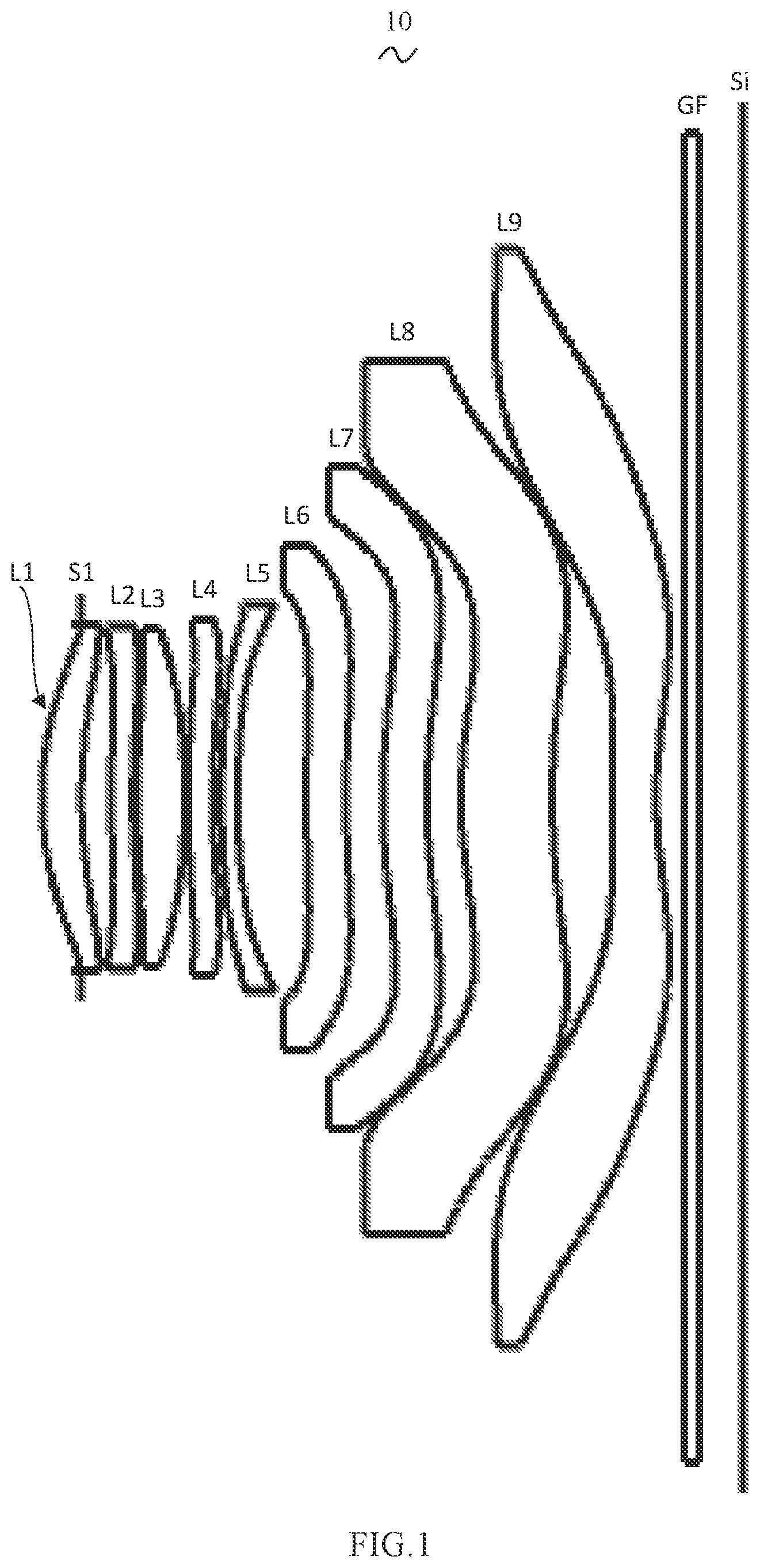
Referring to , the present invention provides a camera optical lens 10 . shows the camera optical lens 10 according to Embodiment 1 of the present invention. The camera optical lens 10 includes nine lenses. The camera optical lens 10 includes, from an object side to an image side, an aperture S1, a first lens L1, a second lens L2, a third lens L3, a fourth lens L4, a fifth lens L5, a sixth lens L6, a seventh lens L7, an eighth lens L8, and a ninth lens L9. An optical element such as an optical filter GF may be arranged between the ninth lens L9 and an image plane S1.
In this embodiment, the first lens L1 has positive refractive power, the second lens L2 has negative refractive power, the third lens L3 has positive refractive power, the fourth lens L4 has positive refractive power, the fifth lens L5 has negative refractive power, the sixth lens L6 has negative refractive power, the seventh lens L7 has negative refractive power, the eighth lens L8 has positive refractive power, and the ninth lens L9 has negative refractive power. It may be understood that, in other embodiments, refractive power of the third lens L3, the fourth lens L4, the fifth lens L5, the sixth lens L6, the seventh lens L7, the eighth lens L8 and the ninth lens L9 may change.
In this embodiment, the first lens L1, the second lens L2, the third lens L3, the fourth lens L4, the fifth lens L5, the sixth lens L6, the seventh lens L7, the eighth lens L8, and the ninth lens L9 are each made of a plastic material. In other embodiments, the lenses may also be made of a material other than the plastic material.
In this embodiment, a focal length of the camera optical lens 10 is defined as f, and a focal length of the first lens L1 is defined as f1. The focal length f and the focal length f1 satisfy a following condition: 2.00f1/f≤5.50, which specifies a ratio of the focal length of the first lens to the focal length of the camera optical lens. Within the range of the above condition, spherical aberration and field curvature of the system may be effectively balanced.
An on-axis thickness of the eighth lens L8 is defined as d15, an on-axis distance from an image side surface of the eighth lens L8 to an object side surface of the ninth lens L9 is defined as d16. The on-axis thickness d15 and the on-axis distance d16 satisfy a following condition: 1.50≤d15/d16≤9.00. Within the range of the above condition, it is beneficial to process lenses and assemble the camera lens.
A central curvature radius of an object side surface of the ninth lens L9 is defined as R17, and a central curvature radius of an image side surface of the ninth lens L9 is defined as R18. The central curvature radius R17 and the central curvature radius R18 satisfy a following condition: 1.00≤(R17+R18)/(R17−R18)≤3.50, which specifies a shape of the ninth lens L9. Within the specified range of the condition, a degree of deflection of light passing through the lens may be alleviated, and aberrations may be effectively reduced.
In this embodiment, the object side surface of the first lens L1 is convex in a paraxial region, and the image side surface of the first lens L1 is concave in the paraxial region.
A central curvature radius of the object side surface of the first lens L1 is defined as R1, and a central curvature radius of the image side surface of the first lens L1 is defined as R2. The central curvature radius R1 and the central curvature radius R2 satisfy a following condition: −35.14≤(R1+R2)/(R1−R2)≤−3.11. The shape of the first lens L1 is reasonably controlled so that the first lens L1 may effectively correct spherical aberration of the system. Optionally, the central curvature radius R1 and the central curvature radius R2 satisfy a following condition: −21.96≤(R1+R2)/(R1−R2)≤−3.89.
The on-axis thickness of the first lens L1 is defined as d1, and a total optical length from the object side surface of the first lens L1 to the image plane S1 of the camera optical lens 10 along an optic axis is defined as TTL. The on-axis thickness d1 and the total optical length TTL satisfy a following condition: 0.02≤d1/TTL≤0.08. Within the range of the above condition, it is beneficial to achieve an ultra-thinness effect. Optionally, the on-axis thickness d1 and the total optical length TTL satisfy a following condition: 0.03≤d1/TTL≤0.07.
In this embodiment, the object side surface of the second lens L2 is convex in a paraxial region, and the image side surface of the second lens L2 is concave in the paraxial region.
The focal length of the camera optical lens 10 is defined as f, a focal length of the second lens L2 is defined as f2. The focal length f and the focal length f2 satisfy a following condition: −8.12≤f2/f≤−2.48. By controlling the negative refractive power of the second lens L2 in the reasonable range, it is beneficial to correct the aberration of the optical system. Optionally, the focal length f and the focal length f2 satisfy a following condition: −5.08≤f2/f≤−3.10.
A central curvature radius of an object side surface of the second lens L2 is defined as R3, and a central curvature radius of an image side surface of the second lens L2 is defined as R4. The central curvature radius R3 and the central curvature radius R4 satisfy a following condition: 2.14≤(R3+R4)/(R3−R4)≤10.66, which specifies a shape of the second lens L2. Within the range of the above condition, as the lens becomes ultra-thinness and wide-angle, it is beneficial to correct on-axis chromatic aberration. Optionally, the central curvature radius R3 and the central curvature radius R4 satisfy a following condition: 3.42≤(R3+R4)/(R3−R4)≤8.53.
An on-axis thickness of the second lens L2 is defined as d3, and a total optical length from the object side surface of the first lens L1 to the image plane S1 of the camera optical lens 10 along an optic axis is defined as TTL. The on-axis thickness d3 and the total optical length TTL satisfy a following condition: 0.01≤d3/TTL≤0.05. Within the range of the above condition, it is beneficial to achieve an ultra-thinness effect. Optionally, the on-axis thickness d3 and the total optical length TTL satisfy a following condition: 0.02≤d3/TTL≤0.04.
In this embodiment, the object side surface of the third lens L3 is convex in a paraxial region, and the image side surface of the third lens L3 is convex in the paraxial region.
The focal length of the camera optical lens 10 is defined as f, and a focal length of the third lens L3 is defined as f3. The focal length f and the focal length f3 satisfy a following condition: 0.48≤f3/f≤1.83. With appropriate configuration of the refractive power, the system may obtain better imaging quality and lower sensitivity. Optionally, the focal length f and the focal length f3 satisfy a following condition: 0.77≤f3/f≤1.46.
A central curvature radius of an object side surface of the third lens L3 is defined as R5, and a central curvature radius of an image side surface of the third lens L3 is defined as R6. The central curvature radius R5 and the central curvature radius R6 satisfy a following condition: −1.30≤(R5+R6)/(R5−R6)≤−0.16, which specifies a shape of the third lens L3. Within the specified range of the condition, a degree of deflection of light passing through the lens may be alleviated, and aberrations may be effectively reduced. Optionally, the central curvature radius R5 and the central curvature radius R6 satisfy a following condition: −0.81≤(R5+R6)/(R5−R6)≤−0.20.
A total optical length from the object side surface of the first lens L1 to the image plane S1 of the camera optical lens 10 along an optic axis is defined as TTL, and an on-axis thickness of the third lens L3 is defined as d5. The on-axis thickness d3 and the total optical length TTL satisfy a following condition: 0.03≤d5/TTL≤0.12. Within the range of the above condition, it is beneficial to achieve an ultra-thinness effect. Optionally, the on-axis thickness d3 and the total optical length TTL satisfy a following condition: 0.05≤d5/TTL≤0.10.
In this embodiment, the object side surface of the fourth lens L4 is convex in a paraxial region, and the image side surface of the fourth lens L4 is concave in the paraxial region.
The focal length of the camera optical lens 10 is defined as f, and a focal length of the fourth lens L4 is defined as f4. The focal length f and the focal length f4 satisfy a following condition: 2.22≤f4/f≤10.54. With appropriate configuration of the refractive power, the system may obtain better imaging quality and lower sensitivity. Optionally, the focal length f and the focal length f4 satisfy a following condition: 3.56≤f4/f≤8.43.
A central curvature radius of an object side surface of the fourth lens L4 is defined as R7, and a central curvature radius of an image side surface of the fourth lens L4 is defined as R8. The central curvature radius R7 and the central curvature radius R8 satisfy a following condition: −12.60≤(R7+R8)/(R7−R8)≤−2.54, which specifies a shape of the fourth lens L4. Within the range of the above condition, it is beneficial to correct the aberration of off-axis angle with the development of ultra-thinness and wide-angle. Optionally, the central curvature radius R7 and the central curvature radius R8 satisfy a following condition: −7.87≤(R7+R8)/(R7−R8)≤−3.18.
A total optical length from the object side surface of the first lens L1 to the image plane S1 of the camera optical lens 10 along an optic axis is defined as TTL, and an on-axis thickness of the fourth lens L4 is defined as d7. The on-axis thickness d7 and the total optical length TTL satisfy a following condition: 0.02≤d7/TTL≤0.05. Within the range of the above condition, it is beneficial to achieve an ultra-thinness effect. Optionally, the on-axis thickness d7 and the total optical length TTL satisfy a following condition: 0.03≤d7/TTL≤0.04.
In this embodiment, the object side surface of the fifth lens L5 is convex in a paraxial region, and the image side surface of the fifth lens L5 is concave in the paraxial region.
A focal length of the fifth lens L5 is defined as f5, and the focal length of the camera optical lens 10 is defined as f. The focal length f and the focal length f5 satisfy a following condition: −8.56≤f5/f≤−2.36. With appropriate configuration of the refractive power, the system may obtain better imaging quality and lower sensitivity. Optionally, the focal length f and the focal length f5 satisfy a following condition: −5.35≤f5/f≤−2.95.
A central curvature radius of an object side surface of the fifth lens L5 is defined as R9, and a central curvature radius of an image side surface of the fifth lens L5 is defined as R10. The central curvature radius R9 and the central curvature radius R10 satisfy a following condition: 2.19≤(R9+R10)/(R9−R10)≤8.15, which specifies a shape of the fifth lens L5. Within the range of the above condition, it is beneficial to correct the aberration of off-axis angle with the development of ultra-thinness and wide-angle. Optionally, the central curvature radius R9 and the central curvature radius R10 satisfy a following condition: 3.50≤(R9+R10)/(R9−R10)≤6.52.
A total optical length from the object side surface of the first lens L1 to the image plane S1 of the camera optical lens 10 along an optic axis is defined as TTL, and an on-axis thickness of the fifth lens L5 is defined as d9. The on-axis thickness d9 and the total optical length TTL satisfy a following condition: 0.01≤d9/TTL≤0.03. Within the range of the condition, it is beneficial to achieve an ultra-thinness effect. Optionally, the on-axis thickness d9 and the total optical length TTL satisfy a following condition: 0.02≤d9/TTL≤0.03.
In this embodiment, the object side surface of the sixth lens L6 is convex in a paraxial region, and the image side surface of the sixth lens L6 is concave in the paraxial region.
The focal length of the camera optical lens 10 is defined as f, and a focal length of the sixth lens L6 is defined as f6. The focal length f and the focal length f6 satisfy a following condition: −21.54≤f6/f≤−4.42. With appropriate configuration of the refractive power, the system may obtain better imaging quality and lower sensitivity. Optionally, the focal length f and the focal length f6 satisfy a following condition: −13.46≤f6/f≤−5.52.
A central curvature radius of an object side surface of the sixth lens L6 is defined as R11, and a central curvature radius of an image side surface of the sixth lens L6 is defined as R12. The central curvature radius R11 and the central curvature radius R12 satisfy a following condition: 3.09≤(R11+R12)/(R11−R12)≤20.04, which specifies a shape of the sixth lens L6. Within the range of the above condition, it is beneficial to correct the aberration of off-axis angle with the development of ultra-thinness and wide-angle. Optionally, the central curvature radius R11 and the central curvature radius R12 satisfy a following condition: 4.95≤(R11+R12)/(R11−R12)≤16.03.
A total optical length from the object side surface of the first lens L1 to the image plane S1 of the camera optical lens 10 along an optic axis is defined as TTL, and an on-axis thickness of the sixth lens L6 is defined as d11. The on-axis thickness d11 and the total optical length TTL satisfy a following condition: 0.02≤d11/TTL≤0.08. Within the range of the condition, it is beneficial to achieve an ultra-thinness effect. Optionally, the on-axis thickness d11 and the total optical length TTL satisfy a following condition: 0.03≤d11/TTL≤0.07.
In this embodiment, the object side surface of the seventh lens L7 is convex in a paraxial region, and the image side surface of the seventh lens L7 is concave in the paraxial region.
The focal length of the camera optical lens 10 is defined as f, and a focal length of the seventh lens L7 is defined as f7. The focal length f and the focal length f7 satisfy a following condition: −45.71≤f7/f≤−5.01. With appropriate configuration of the refractive power, the system may obtain better imaging quality and lower sensitivity. Optionally, the focal length f and the focal length f7 satisfy a following condition: −28.57≤f7/f≤−6.27.
A central curvature radius of an object side surface of the seventh lens L7 is defined as R13, and a central curvature radius of an image side surface of the seventh lens L7 is defined as R14. The central curvature radius R13 and the central curvature radius R14 satisfy a following condition: 5.48≤(R13+R14)/(R13−R14)≤33.29, which specifies a shape of the seventh lens L7. Within the range of the above condition, it is beneficial to correct the aberration of off-axis angle with the development of ultra-thinness and wide-angle. Optionally, the central curvature radius R13 and the central curvature radius R14 satisfy a following condition: 8.78≤(R13+R14)/(R13−R14)≤26.63.
A total optical length from the object side surface of the first lens L1 to the image plane S1 of the camera optical lens 10 along an optic axis is defined as TTL, and an on-axis thickness of the seventh lens L7 is defined as d13. The on-axis thickness d13 and the total optical length TTL satisfy a following condition: 0.03≤d13/TTL≤0.09. Within the range of the condition, it is beneficial to achieve an ultra-thinness effect. Optionally, the on-axis thickness d13 and the total optical length TTL satisfy a following condition: 0.05≤d13/TTL≤0.08.
In this embodiment, the object side surface of the eighth lens L8 is convex in a paraxial region, and the image side surface of the eighth lens L8 is concave in the paraxial region.
The focal length of the camera optical lens 10 is defined as f, and a focal length of the eighth lens L8 is defined as f8. The focal length f and the focal length f8 satisfy a following condition: 0.36≤f8/f≤2.87. With appropriate configuration of the refractive power, the system may obtain better imaging quality and lower sensitivity. Optionally, the focal length f and the focal length f8 satisfy a following condition: 0.57≤f8/f≤2.30.
A central curvature radius of an object side surface of the eighth lens L8 is defined as R15, and a central curvature radius of an image side surface of the eighth lens L8 is defined as R16. The central curvature radius R15 and the central curvature radius R16 satisfy a following condition: −6.01≤(R15+R16)/(R15−R16)≤0.37, which specifies a shape of the eighth lens. Within the range of the above condition, it is beneficial to correct the aberration of off-axis angle with the development of ultra-thinness and wide-angle. Optionally, the central curvature radius R15 and the central curvature radius R16 satisfy a following condition: −3.76≤(R15+R16)/(R15−R16)≤0.30.
A total optical length from the object side surface of the first lens L1 to the image plane S1 of the camera optical lens 10 along an optic axis is defined as TTL, and an on-axis thickness of the eighth lens L8 is defined as d15. The on-axis thickness d15 and the total optical length TTL satisfy a following condition: 0.07≤d15/TTL≤0.24. Within the range of the above condition, it is beneficial to achieve an ultra-thinness effect. Optionally, the on-axis thickness d15 and the total optical length TTL satisfy a following condition: 0.10≤d15/TTL≤0.19.
In this embodiment, the object side surface of the ninth lens L9 is convex in a paraxial region, and the image side surface of the ninth lens L9 is concave in the paraxial region.
The focal length of the camera optical lens 10 is defined as f, and a focal length of the ninth lens L9 is defined as f9. The focal length f and the focal length f9 satisfy a following condition: −2.21≤f9/f≤−0.35. With appropriate configuration of the refractive power, the system may obtain better imaging quality and lower sensitivity. Optionally, the focal length f and the focal length f9 satisfy a following condition: −1.38≤f9/f≤−0.44.
A total optical length from the object side surface of the first lens L1 to the image plane S1 of the camera optical lens 10 along an optic axis is defined as TTL, and an on-axis thickness of the ninth lens L9 is defined as d17. The on-axis thickness d17 and the total optical length TTL satisfy a following condition: 0.02≤d17/TTL≤0.09. Within the range of the condition, it is beneficial to achieve an ultra-thinness effect. Optionally, the on-axis thickness d17 and the total optical length TTL satisfy a following condition: 0.03≤d17/TTL≤0.08.
In this embodiment, an image height of the camera optical lens 10 is IH, and a total optical length from the object side surface of the first lens L1 to the image plane S1 of the camera optical lens 10 along an optic axis is defined as TTL. The image height IH and the total optical length TTL satisfy a following condition: TTL/IH≤1.21. Within the range of the condition, it is beneficial to achieve an ultra-thinness effect.
In this embodiment, a field of view FOV of the camera optical lens 10 is greater than or equal to 89.00°, so that a wide-angle effect is achieved.
In this embodiment, an F number FNO of the camera optical lens 10 is less than or equal to 1.95, so that a large aperture is achieved, thereby obtaining a good imaging quality of the camera optical lens.
When the above conditions are satisfied, the camera optical lens 10 may meet the design requirements for large aperture, wide-angle and ultra-thinness while maintaining good optical performances. According to properties of the camera optical lens 10 , the camera optical lens 10 is especially suitable for mobile phone camera lens components composed of high-pixel CCD, CMOS and other imaging elements and WEB camera lens.
The camera optical lens 10 of the present invention will be described below with examples. The symbols recorded in each example will be described as follows. The focal length, on-axis distance, central curvature radius, on-axis thickness, inflection point position, and arrest point position are each in unit of millimeter (mm).
TTL denotes a total optical length (on-axis distance from the object side surface of the first lens L1 to the image plane S1), with a unit of millimeter (mm).
F number FNO denotes a ratio of an effective focal length of the camera optical lens to an entrance pupil diameter.
Optionally, the object side surface and/or the image side surface of the lens may be provided with inflection points and/or arrest points in order to meet high-quality imaging requirements. The description below may be referred to in specific embodiments as follows.
Design data of the camera optical lens 10 according to Embodiment 1 of the present invention are shown in Tables 1 and 2.
TABLE 1
R d nd vd
S1 ∞ d0= −0.519
R1 3.415 d1= 0.539 nd1 1.5450 v1 55.81
R2 5.280 d2= 0.409
R3 11.983 d3= 0.289 nd2 1.6700 v2 19.39
R4 7.438 d4= 0.069
R5 8.470 d5= 0.643 nd3 1.5450 v3 55.81
R6 −13.874 d6= 0.048
R7 8.706 d7= 0.344 nd4 1.5444 v4 55.82
R8 11.992 d8= 0.112
R9 10.010 d9= 0.221 nd5 1.6610 v5 20.53
R10 6.897 d10= 0.942
R11 12.808 d11= 0.542 nd6 1.6610 v6 20.53
R12 9.241 d12= 0.506
R13 6.176 d13= 0.599 nd7 1.6610 v7 20.53
R14 5.144 d14= 0.471
R15 4.344 d15= 1.252 nd8 1.5450 v8 55.81
R16 8.678 d16= 0.830
R17 53.268 d17= 0.593 nd9 1.5450 v9 55.81
R18 4.259 d18= 0.375
R19 ∞ d19= 0.210 ndg 1.5168 vg 64.17
R20 ∞ d20= 0.613
The reference signs are explained as follows.
S1: aperture;
R: central curvature radius of an optical surface;
R1: central curvature radius of the object side surface of the first lens L1;
R2: central curvature radius of the image side surface of the first lens L1;
R3: central curvature radius of the object side surface of the second lens L2;
R4: central curvature radius of the image side surface of the second lens L2;
R5: central curvature radius of the object side surface of the third lens L3;
R6: central curvature radius of the image side surface of the third lens L3;
R7: central curvature radius of the object side surface of the fourth lens L4;
R8: central curvature radius of the image side surface of the fourth lens L4;
R9: central curvature radius of the object side surface of the fifth lens L5;
R10: central curvature radius of the image side surface of the fifth lens L5;
R11: central curvature radius of the object side surface of the sixth lens L6;
R12: central curvature radius of the image side surface of the sixth lens L6;
R13: central curvature radius of the object side surface of the seventh lens L7;
R14: central curvature radius of the image side surface of the seventh lens L7;
R15: central curvature radius of the object side surface of the eighth lens L8;
R16: central curvature radius of the image side surface of the eighth lens L8;
R17: central curvature radius of the object side surface of the ninth lens L9;
R18: central curvature radius of the image side surface of the ninth lens L9;
R19: central curvature radius of the object side surface of the optical filter GF;
R20: central curvature radius of the image side surface of the optical filter GF;
d: on-axis thickness of a lens and an on-axis distance between lenses;
d0: on-axis distance from the aperture S1 to the object side surface of the first lens L1;
d1: on-axis thickness of the first lens L1;
d2: on-axis distance from the image side surface of the first lens L1 to the object side surface of the second lens L2;
d3: on-axis thickness of the second lens L2;
d4: on-axis distance from the image side surface of the second lens L2 to the object side surface of the third lens L3;
d5: on-axis thickness of the third lens L3;
d6: on-axis distance from the image side surface of the third lens L3 to the object side surface of the fourth lens L4;
d7: on-axis thickness of the fourth lens L4;
d8: on-axis distance from the image side surface of the fourth lens L4 to the object side surface of the fifth lens L5;
d9: on-axis thickness of the fifth lens L5;
d10: on-axis distance from the image side surface of the fifth lens L5 to the object side surface of the sixth lens L6;
d11: on-axis thickness of the sixth lens L6;
d12: on-axis distance from the image side surface of the sixth lens L6 to the object side surface of the seventh lens L7;
d13: on-axis thickness of the seventh lens L7;
d14: on-axis distance from the image side surface of the seventh lens L7 to the object side surface of the eighth lens L8;
d15: on-axis thickness of the eighth lens L8;
d16: on-axis distance from the image side surface of the eighth lens L8 to the object side surface of the ninth lens L9;
d17: on-axis thickness of the ninth lens L9;
d18: on-axis distance from the image side surface of the ninth lens L9 to the object side surface of the optical filter GF;
d19: on-axis thickness of the optical filter GF;
d20: on-axis distance from the image side surface of the optical filter GF to the image plane;
nd: refractive index of a d-line;
nd1: refractive index of the d-line of the first lens L1;
nd2: refractive index of the d-line of the second lens L2;
nd3: refractive index of the d-line of the third lens L3;
nd4: refractive index of the d-line of the fourth lens L4;
nd5: refractive index of the d-line of the fifth lens L5;
nd6: refractive index of the d-line of the sixth lens L6;
nd7: refractive index of the d-line of the seventh lens L7;
nd8: refractive index of the d-line of the eighth lens L8;
nd9: refractive index of the d-line of the ninth lens L9;
ndg: refractive index of the d-line of the optical filter GF;
vd: Abbe number;
v1: Abbe number of the first lens L1;
v2: Abbe number of the second lens L2;
v3: Abbe number of the third lens L3;
v4: Abbe number of the fourth lens L4;
v5: Abbe number of the fifth lens L5;
v6: Abbe number of the sixth lens L6;
v7: Abbe number of the seventh lens L7;
v8: Abbe number of the eighth lens L8;
v9: Abbe number of the ninth lens L9;
vg: Abbe number of the optical filter GF.
Table 2 shows aspherical surface data of each lens in the camera optical lens 10 according to Embodiment 1 of the present invention.
TABLE 2
Conic
coefficient Aspherical surface coefficient
k A4 A6 A8 A10 A12
R1 2.3604E−02 −2.3424E−03 −2.8686E−04 −2.8633E−04 9.0803E−06 6.4004E−05
R2 −7.8104E+00 2.4012E−03 −1.1263E−03 −1.0220E−03 1.0771E−03 −6.5338E−04
R3 1.1368E+01 −1.6958E−02 −7.1910E−04 1.2868E−04 5.3949E−04 −4.7023E−04
R4 −6.8969E+01 3.2723E−03 −1.2895E−02 7.0244E−03 −1.6167E−03 −9.6735E−05
R5 −1.4916E+01 −9.9896E−03 −1.8068E−03 −1.8891E−04 2.1848E−03 −1.3887E−03
R6 3.7876E+01 −5.0338E−02 3.9022E−02 −2.2304E−02 9.1784E−03 −2.5461E−03
R7 −5.1003E+01 −2.0751E−02 2.0973E−02 −1.0508E−02 2.6653E−03 −3.4933E−04
R8 −4.8972E+00 2.1215E−02 −2.2904E−02 1.4594E−02 −6.8227E−03 1.8079E−03
R9 1.4709E+01 −4.4985E−03 1.7660E−03 −2.2068E−03 3.1687E−03 −1.9924E−03
R10 6.9017E+00 −1.3293E−02 7.2562E−03 −3.5416E−03 2.0750E−03 −7.4534E−04
R11 −7.0281E+01 −7.2790E−03 3.0571E−04 −1.0508E−03 8.0910E−04 −3.5454E−04
R12 −4.8840E+01 −6.1832E−03 9.0192E−04 −1.4657E−03 7.7701E−04 −2.3164E−04
R13 −4.2477E+01 2.7038E−03 3.1755E−04 −9.5947E−04 3.3088E−04 −7.6056E−05
R14 −3.5140E+01 −2.2041E−03 5.3373E−04 −9.6864E−05 −6.1465E−05 2.1140E−05
R15 −1.8454E+01 4.0306E−03 −5.3915E−03 1.1979E−03 −1.7871E−04 1.6509E−05
R16 −5.5310E−01 7.7268E−03 −4.6516E−03 7.7335E−04 −8.0614E−05 5.2795E−06
R17 −9.8759E+01 −1.7832E−02 1.0501E−03 −1.9717E−06 −2.1122E−06 1.0252E−07
R18 −1.1609E+01 −1.1136E−02 1.1896E−04 7.0113E−05 −6.0220E−06 2.3267E−07
Conic
coefficient Aspherical surface coefficient
k A14 A16 A18 A20
R1 2.3604E−02 −4.7258E−05 1.4338E−05 −2.1477E−06 1.2726E−07
R2 −7.8104E+00 2.2983E−04 −4.6981E−05 5.1253E−06 −2.2769E−07
R3 1.1368E+01 1.9607E−04 −4.5309E−05 5.5996E−06 −2.8777E−07
R4 −6.8969E+01 9.4765E−05 −3.4713E−06 −2.7904E−06 2.9714E−07
R5 −1.4916E+01 3.2178E−04 −1.1633E−05 −5.6202E−06 5.7830E−07
R6 3.7876E+01 4.2516E−04 −3.0765E−05 −9.6024E−07 2.0574E−07
R7 −5.1003E+01 −1.1247E−05 1.5311E−05 −2.7071E−06 1.6909E−07
R8 −4.8972E+00 −2.3935E−04 8.5009E−06 1.2391E−06 −1.0171E−07
R9 1.4709E+01 6.8025E−04 −1.3382E−04 1.4301E−05 −6.4830E−07
R10 6.9017E+00 1.5143E−04 −1.7945E−05 1.1860E−06 −3.6924E−08
R11 −7.0281E+01 9.2503E−05 −1.4895E−05 1.3771E−06 −5.7197E−08
R12 −4.8840E+01 4.1605E−05 −4.5280E−06 2.7636E−07 −7.2407E−09
R13 −4.2477E+01 1.2133E−05 −1.2519E−06 7.1985E−08 −1.7031E−09
R14 −3.5140E+01 −2.9889E−06 2.2381E−07 −8.7283E−09 1.3990E−10
R15 −1.8454E+01 −9.0198E−07 2.8599E−08 −4.8925E−10 3.5053E−12
R16 −5.5310E−01 −2.1051E−07 4.9209E−09 −6.1681E−11 3.1891E−13
R17 −9.8759E+01 −2.4093E−09 3.1514E−11 −2.1997E−13 6.4122E−16
R18 −1.1609E+01 −4.9007E−09 5.7479E−11 −3.4993E−13 8.5666E−16
Here, k denotes a conic coefficient, and A4, A6, A8, A10, A12, A14, A16, A18, and A20 denote an aspherical coefficient, respectively. y =( x 2 /R )/{1+[1−( k+ 1)( x 2 /R 2 )] 1/2 }+A 4 x 4 +A 6 x 6 +A 8 x 8 +A 10 x 10 +A 12 x 12 +A 14 x 14 +A 16 x 16 +A 18 x 18 +A 20 x 20 (1)
Here, x denotes a vertical distance between a point on an aspherical curve and the optical axis, and y denotes a depth of the aspherical surface, i.e., a vertical distance between a point on the aspherical surface having a distance x from the optical axis and a tangent plane tangent to a vertex on an aspherical optical axis.
For convenience, the aspherical surface of each lens surface uses the aspherical surface shown in the above formula (1). However, the present invention is not limited to the aspherical polynomial form shown in the formula (1).
Design data of the inflection point and the arrest point of each lens in the camera optical lens 10 according to Embodiment 1 of the present invention are shown in Tables 3 and 4. Here, P1R1 and P1R2 denote the object side surface and image side surface of the first lens L1, respectively. P2R1 and P2R2 denote the object side surface and image side surface of the second lens L2, respectively. P3R1 and P3R2 denote the object side surface and image side surface of the third lens L3, respectively. P4R1 and P4R2 denote the object side surface and image side surface of the fourth lens L4, respectively. P5R1 and P5R2 denote the object side surface and image side surface of the fifth lens L5, respectively. P6R1 and P6R2 denote the object side surface and image side surface of the sixth lens L6, respectively. P7R1 and P7R2 denote the object side surface and image side surface of the seventh lens L7, respectively. P8R1 and P8R2 denote the object side surface and image side surface of the eighth lens L8, respectively. P9R1 and P9R2 denote the object side surface and image side surface of the ninth lens L9, respectively. Data in an “inflection point position” column are a vertical distance from an inflexion point provided on a surface of each lens to the optical axis of the camera optical lens 10 . Data in an “arrest point position” column are a vertical distance from an arrest point provided on the surface of each lens to the optical axis of the camera optical lens 10 .
TABLE 3
Number of Inflexion Inflexion Inflexion
inflexion point point point
points position 1 position 2 position 3
P1R1 1 1.665 /
P1R2 1 1.335 / /
P2R1 1 0.655 / /
P2R2 1 0.805 / /
P3R1 3 0.875 1.805 1.915
P3R2 1 1.935 / /
P4R1 2 1.185 2.005 /
P4R2 1 1.115 / /
P5R1 1 1.995 / /
P5R2 1 2.165 / /
P6R1 1 0.785 / /
P6R2 1 0.895 / /
P7R1 2 1.315 3.135 /
P7R2 2 1.255 3.785 /
P8R1 2 1.075 3.405 /
P8R2 2 1.405 3.955 /
P9R1 3 0.305 3.175 6.035
P9R2 3 0.985 5.305 6.135
TABLE 4
Number of
arrest Arrest point Arrest point
points position 1 position 2
P1R1 0 / /
P1R2 1 1.965 /
P2R1 1 1.135 /
P2R2 1 1.485 /
P3R1 1 1.665 /
P3R2 0 / /
P4R1 1 1.675 /
P4R2 1 1.595 /
P5R1 0 / /
P5R2 0 / /
P6R1 1 1.345 /
P6R2 1 1.545 /
P7R1 1 2.045 /
P7R2 1 2.165 /
P8R1 1 1.865 /
P8R2 1 2.245 /
P9R1 2 0.515 5.555
P9R2 1 1.895 /
and are schematic diagrams of a longitudinal aberration and a lateral color of the camera optical lens 10 after light having a wavelength of 656 nm, 587 nm, 546 nm, 486 nm, and 435 nm passes through the camera optical lens 10 according to Embodiment 1, respectively. is a schematic diagram of a field curvature and a distortion of the camera optical lens 10 after light having a wavelength of 546 nm passes through the camera optical lens 10 according to Embodiment 1. A field curvature S in is a field curvature in a sagittal direction, and T is a field curvature in a meridian direction.
Table 13 below shows numerical values corresponding to various numerical values in Embodiments 1, 2, and 3 and parameters specified in the conditions.
As shown in Table 13, Embodiment 1 satisfies various conditions.
In this embodiment, an entrance pupil diameter ENPD of the camera optical lens 10 is 4.090 mm, a full-field image height IH is 8.000 mm, and a field of view FOV in a diagonal direction is 89.00°. The satisfy design requirements for large aperture, wide-angle and ultra-thinness. The on-axis and off-axis chromatic aberrations are fully corrected, thereby achieving excellent optical performances.
Embodiment 2
Embodiment 2 is basically the same as Embodiment 1, and involves symbols having the same meanings as Embodiment 1, and only differences therebetween are listed below.
Design data of the camera optical lens 20 according to Embodiment 2 of the present invention are shown in Tables 5 and 6.
TABLE 5
R d nd vd
S1 ∞ d0= −0.448
R1 3.341 d1= 0.408 nd1 1.5450 v1 55.81
R2 4.009 d2= 0.333
R3 7.562 d3= 0.289 nd2 1.6700 v2 19.39
R4 5.512 d4= 0.111
R5 5.781 d5= 0.721 nd3 1.5450 v3 55.81
R6 −14.851 d6= 0.069
R7 10.546 d7= 0.344 nd4 1.5444 v4 55.82
R8 16.825 d8= 0.131
R9 10.382 d9= 0.221 nd5 1.6610 v5 20.53
R10 6.829 d10= 1.003
R11 7.650 d11= 0.344 nd6 1.6610 v6 20.53
R12 6.540 d12= 0.566
R13 5.636 d13= 0.607 nd7 1.6610 v7 20.53
R14 5.150 d14= 0.533
R15 7.226 d15= 1.346 nd8 1.5450 v8 55.81
R16 57.038 d16= 0.303
R17 3.705 d17= 0.601 nd9 1.5450 v9 55.81
R18 1.958 d18= 0.700
R19 ∞ d19= 0.210 ndg 1.5168 vg 64.17
R20 ∞ d20= 0.767
Table 6 shows aspherical surface data of each lens in the camera optical lens 20 according to Embodiment 2 of the present invention.
TABLE 6
Conic
coefficient Aspherical surface coefficient
k A4 A6 A8 A10 A12
R1 −1.9752E−01 −3.0641E−03 8.3914E−05 −1.5386E−03 1.0404E−03 −4.8568E−04
R2 −6.9397E+00 9.1391E−03 −2.9201E−03 −7.0451E−04 6.0422E−04 −2.9427E−04
R3 5.0837E+00 −1.9564E−02 3.2597E−03 −4.8290E−03 3.4900E−03 −1.5047E−03
R4 −4.4731E+01 8.1841E−03 −1.2905E−02 5.3488E−03 −1.5275E−03 5.4477E−04
R5 −1.2223E+01 −9.8104E−03 4.8912E−03 −5.7855E−03 4.0599E−03 −1.4979E−03
R6 3.9176E+01 −4.8593E−02 3.7618E−02 −2.2399E−02 1.0038E−02 −3.1853E−03
R7 −6.1119E+01 −2.6379E−02 2.9213E−02 −1.8299E−02 8.1990E−03 −2.8871E−03
R8 6.4446E+00 1.5809E−02 −1.3314E−02 5.3087E−03 −1.3020E−03 −1.8654E−04
R9 1.5827E+01 1.4017E−04 −3.1071E−03 1.5694E−04 1.7410E−03 −1.1155E−03
R10 6.4690E+00 −7.7856E−03 1.9986E−03 −5.6900E−04 7.1345E−04 −2.6718E−04
R11 −3.3626E+01 −5.3288E−03 6.9101E−04 −1.6891E−03 9.6909E−04 −3.2031E−04
R12 −4.9868E+01 3.2931E−03 −4.3138E−03 4.2606E−04 2.4128E−04 −1.2051E−04
R13 −2.3999E+01 −3.1009E−04 2.6051E−03 −2.2846E−03 8.4087E−04 −2.0281E−04
R14 −2.8776E+01 5.1948E−03 −2.8971E−03 7.8345E−04 −2.1434E−04 4.0261E−05
R15 −3.2501E+01 9.2906E−03 −5.8419E−03 1.0517E−03 −1.5893E−04 1.7175E−05
R16 −8.6925E+01 2.0339E−02 −6.1255E−03 7.8634E−04 −6.3990E−05 3.3928E−06
R17 −1.6939E+01 −2.5917E−02 3.0422E−03 −2.1513E−04 1.0112E−05 −3.1339E−07
R18 −5.8953E+00 −1.9587E−02 2.0660E−03 −1.3310E−04 5.5666E−06 −1.5403E−07
Conic
coefficient Aspherical surface coefficient
k A14 A16 A18 A20
R1 −1.9752E−01 1.3674E−04 −2.4043E−05 2.4123E−06 −1.0670E−07
R2 −6.9397E+00 8.0329E−05 −1.5069E−05 1.9447E−06 −1.1315E−07
R3 5.0837E+00 3.9604E−04 −6.1271E−05 5.0762E−06 −1.6464E−07
R4 −4.4731E+01 −2.5728E−04 7.9824E−05 −1.2427E−05 7.5285E−07
R5 −1.2223E+01 2.7073E−04 −1.5112E−05 −1.7004E−06 1.9245E−07
R6 3.9176E+01 6.8526E−04 −9.4650E−05 7.6541E−06 −2.7785E−07
R7 −6.1119E+01 7.2240E−04 −1.1631E−04 1.0837E−05 −4.4389E−07
R8 6.4446E+00 2.0157E−04 −5.0364E−05 5.6574E−06 −2.4522E−07
R9 1.5827E+01 3.4565E−04 −6.1149E−05 5.9253E−06 −2.4631E−07
R10 6.4690E+00 4.1358E−05 −2.6444E−06 3.3697E−08 −8.2453E−10
R11 −3.3626E+01 6.5738E−05 −8.8158E−06 7.2789E−07 −2.8457E−08
R12 −4.9868E+01 2.6106E−05 −3.3065E−06 2.4073E−07 −7.6749E−09
R13 −2.3999E+01 3.2221E−05 −3.2108E−06 1.7787E−07 −4.0990E−09
R14 −2.8776E+01 −4.7026E−06 3.2599E−07 −1.2282E−08 1.9401E−10
R15 −3.2501E+01 −1.1123E−06 4.0499E−08 −7.6376E−10 5.8045E−12
R16 −8.6925E+01 −1.1322E−07 2.2570E−09 −2.4359E−11 1.0901E−13
R17 −1.6939E+01 6.2482E−09 −7.6526E−11 5.2123E−13 −1.5055E−15
R18 −5.8953E+00 2.7513E−09 −2.9938E−11 1.7851E−13 −4.4438E−16
Design data of the inflection point and the arrest point of each lens in the camera optical lens 20 according to Embodiment 2 of the present invention are shown in Tables 7 and 8.
TABLE 7
Number of Inflexion Inflexion Inflexion
inflexion point point point
points position 1 position 2 position 3
P1R1 1 1.515 / /
P1R2 1 1.315 / /
P2R1 2 0.805 1.935 /
P2R2 1 0.895 / /
P3R1 1 1.175 / /
P3R2 1 1.915 / /
P4R1 2 1.285 1.965 /
P4R2 2 1.095 2.125 /
P5R1 1 2.155 / /
P5R2 1 2.255 / /
P6R1 1 0.955 / /
P6R2 1 0.985 / /
P7R1 2 1.335 3.055 /
P7R2 2 1.345 3.705 /
P8R1 3 1.155 3.345 3.565
P8R2 3 1.535 4.045 4.775
P9R1 2 0.715 3.565 /
P9R2 2 0.945 5.965 /
TABLE 8
Number of Arrest point
arrest points position 1
P1R1 0 /
P1R2 1 1.895
P2R1 1 1.385
P2R2 1 1.635
P3R1 0 /
P3R2 0 /
P4R1 1 1.715
P4R2 1 1.545
P5R1 0 /
P5R2 0 /
P6R1 1 1.615
P6R2 1 1.685
P7R1 1 2.085
P7R2 1 2.235
P8R1 1 1.805
P8R2 1 2.205
P9R1 1 1.425
P9R2 1 2.255
and are schematic diagrams of a longitudinal aberration and a lateral color of the camera optical lens 20 after light having a wavelength of 656 nm, 587 nm, 546 nm, 486 nm, and 435 nm passes through the camera optical lens 20 according to Embodiment 2, respectively. is a schematic diagram of a field curvature and a distortion after light having a wavelength of 546 nm passes through the camera optical lens 20 according to Embodiment 2.
As shown in Table 13, Embodiment 2 satisfies various conditions.
In this embodiment, an entrance pupil diameter ENPD of the camera optical lens 20 is 4.014 mm, a full-field image height IH is 8.000 mm, and a field of view FOV in a diagonal direction is 90.20°. The camera optical lens 20 satisfies design requirements for large aperture, wide-angle, and ultra-thinness. The on-axis and off-axis chromatic aberrations are fully corrected, thereby achieving excellent optical performances.
Embodiment 3
Embodiment 3 is basically the same as Embodiment 1, and involves symbols having the same meanings as Embodiment 1, and only differences therebetween are listed below.
In this embodiment, the image side surface of the eighth lens L8 is convex in the paraxial region.
Design data of the camera optical lens 30 of Embodiment 3 of the present invention are shown in Tables 9 and 10.
TABLE 9
R d nd vd
S1 ∞ d0= −0.423
R1 3.364 d1= 0.386 nd1 1.5450 v1 55.81
R2 3.770 d2= 0.317
R3 6.433 d3= 0.289 nd2 1.6700 v2 19.39
R4 4.846 d4= 0.132
R5 4.926 d5= 0.791 nd3 1.5450 v3 55.81
R6 −23.107 d6= 0.063
R7 8.078 d7= 0.344 nd4 1.5444 v4 55.82
R8 13.823 d8= 0.149
R9 10.744 d9= 0.221 nd5 1.6610 v5 20.53
R10 6.746 d10= 0.974
R11 7.985 d11= 0.344 nd6 1.6610 v6 20.53
R12 6.873 d12= 0.558
R13 5.286 d13= 0.591 nd7 1.6610 v7 20.53
R14 4.727 d14= 0.561
R15 7.793 d15= 1.546 nd8 1.5450 v8 55.81
R16 −4.709 d16= 0.173
R17 6.824 d17= 0.419 nd9 1.5450 v9 55.81
R18 1.658 d18= 0.700
R19 ∞ d19= 0.210 ndg 1.5168 vg 64.17
R20 ∞ d20= 0.889
Table 10 shows aspherical surface data of each lens in the camera optical lens 30 of Embodiment 3 of the present invention.
TABLE 10
Conic
coefficient Aspherical surface coefficient
k A4 A6 A8 A10 A12
R1 −1.0903E−01 −3.8411E−03 −1.8418E−04 −1.9226E−03 1.4963E−03 −7.6772E−04
R2 −6.2862E+00 1.0536E−02 −3.3676E−03 −1.3655E−03 1.4679E−03 −8.3819E−04
R3 3.3646E+00 −2.0630E−02 2.6317E−03 −4.7539E−03 4.0359E−03 −2.0541E−03
R4 −3.6316E+01 1.3416E−02 −1.9510E−02 1.0283E−02 −3.7292E−03 8.8350E−04
R5 −8.1511E+00 −4.7064E−03 3.3165E−03 −3.7497E−03 2.8750E−03 −1.2933E−03
R6 8.1041E+01 −6.0675E−02 5.1127E−02 −3.1493E−02 1.4305E−02 −4.5615E−03
R7 −6.2044E+01 −3.3443E−02 3.5109E−02 −2.1375E−02 9.0456E−03 −2.9218E−03
R8 −6.0354E+01 1.9136E−02 −1.6237E−02 8.7005E−03 −3.6495E−03 8.4417E−04
R9 1.4215E+01 1.0981E−03 −4.1109E−03 5.4577E−04 1.4268E−03 −8.9245E−04
R10 6.1036E+00 −7.5672E−03 7.4972E−04 1.0950E−04 2.6669E−04 −3.0457E−05
R11 −4.5264E+01 −2.0123E−03 −1.2889E−03 −5.8774E−04 5.8217E−04 −2.4616E−04
R12 −2.9444E+01 −5.2807E−03 1.0014E−03 −1.8700E−03 9.9843E−04 −3.0707E−04
R13 −2.0742E+01 −1.4978E−03 2.3052E−03 −1.9540E−03 7.2796E−04 −1.8295E−04
R14 −2.7053E+01 4.8875E−03 −3.2324E−03 1.0035E−03 −2.8107E−04 5.2377E−05
R15 −6.1962E+01 8.2898E−03 −4.9472E−03 7.9871E−04 −1.2042E−04 1.3770E−05
R16 −5.3473E+01 2.7411E−02 −7.3996E−03 9.1261E−04 −7.0466E−05 3.5366E−06
R17 −9.9000E+01 −1.9493E−02 2.1712E−03 −1.3991E−04 5.9153E−06 −1.6419E−07
R18 −6.9235E+00 −1.9429E−02 2.4907E−03 −2.0054E−04 1.0386E−05 −3.4840E−07
Conic
coefficient Aspherical surface coefficient
k A14 A16 A18 A20
R1 −1.0903E−01 2.3652E−04 −4.4484E−05 4.7007E−06 −2.1215E−07
R2 −6.2862E+00 2.7009E−04 −5.3705E−05 6.3446E−06 −3.2786E−07
R3 3.3646E+00 6.4316E−04 −1.2022E−04 1.2293E−05 −5.2080E−07
R4 −3.6316E+01 −1.3438E−04 1.6384E−05 −2.0712E−06 1.5257E−07
R5 −8.1511E+00 3.4120E−04 −5.0996E−05 3.8341E−06 −1.0574E−07
R6 8.1041E+01 9.7364E−04 −1.2910E−04 9.3393E−06 −2.7160E−07
R7 −6.2044E+01 6.7597E−04 −1.0212E−04 8.9794E−06 −3.4662E−07
R8 −6.0354E+01 −8.8674E−05 2.0483E−07 7.1566E−07 −3.9527E−08
R9 1.4215E+01 2.6046E−04 −4.3217E−05 3.9451E−06 −1.5569E−07
R10 6.1036E+00 −3.1185E−05 9.9348E−06 −1.1265E−06 4.3883E−08
R11 −4.5264E+01 6.1051E−05 −9.6163E−06 8.9021E−07 −3.6860E−08
R12 −2.9444E+01 5.8496E−05 −6.9782E−06 4.8158E−07 −1.4544E−08
R13 −2.0742E+01 3.0438E−05 −3.1661E−06 1.8186E−07 −4.3154E−09
R14 −2.7053E+01 −6.0973E−06 4.2494E−07 −1.6195E−08 2.5954E−10
R15 −6.1962E+01 −9.3387E−07 3.5080E−08 −6.7587E−10 5.2164E−12
R16 −5.3473E+01 −1.1246E−07 2.1525E−09 −2.2437E−11 9.7368E−14
R17 −9.9000E+01 2.9175E−09 −3.1562E−11 1.8763E−13 −4.6731E−16
R18 −6.9235E+00 7.4356E−09 −9.6535E−11 6.9148E−13 −2.0874E−15
Design data of the inflection point and the arrest point of each lens in the camera optical lens 30 according to Embodiment 3 of the present invention are shown in Tables 11 and 12.
TABLE 11
Number of Inflexion Inflexion Inflexion Inflexion
inflexion point point point point
points position 1 position 2 position 3 position 4
P1R1 1 1.455 / / /
P1R2 1 1.295 / / /
P2R1 2 0.845 1.955 / /
P2R2 1 0.915 / / /
P3R1 1 1.775 / / /
P3R2 1 1.735 / / /
P4R1 2 1.235 1.995 / /
P4R2 2 1.125 2.165 / /
P5R1 1 2.205 / / /
P5R2 1 2.305 / / /
P6R1 1 0.965 / / /
P6R2 1 0.975 / / /
P7R1 2 1.305 3.035 / /
P7R2 2 1.315 3.685 / /
P8R1 3 1.115 3.295 3.635 /
P8R2 4 0.585 1.625 4.015 4.765
P9R1 2 0.565 3.375 / /
P9R2 2 0.885 5.785 / /
TABLE 12
Number of Arrest point Arrest point
arrest points position 1 position 2
P1R1 0 / /
P1R2 1 1.875 /
P2R1 1 1.445 /
P2R2 1 1.675 /
P3R1 0 / /
P3R2 0 / /
P4R1 1 1.715 /
P4R2 1 1.595 /
P5R1 0 / /
P5R2 0 / /
P6R1 1 1.635 /
P6R2 1 1.685 /
P7R1 1 2.065 /
P7R2 1 2.225 /
P8R1 1 1.745 /
P8R2 2 1.385 1.825
P9R1 2 1.105 5.875
P9R2 1 2.375 /
and are schematic diagrams of a longitudinal aberration and a lateral color after light having a wavelength of 656 nm, 587 nm, 546 nm, 486 nm, and 435 nm passes through the camera optical lens 30 according to Embodiment 3. is a schematic diagram of a field curvature and a distortion of the camera optical lens 30 after light having a wavelength of 546 nm passes through the camera optical lens 30 according to Embodiment 3.
Table 13 below shows numerical values corresponding to each condition in this embodiment according to the above conditions. It is appreciated that, the cameral optical lens 30 in this embodiment satisfies the above conditions.
In this embodiment, an entrance pupil diameter ENPD of the camera optical lens 30 is 4.013 mm, a full-field image height IH is 8.000 mm, and a field of view FOV in a diagonal direction is 90.20°. The camera optical lens 30 satisfies design requirements for large aperture, wide-angle and ultra-thinness. The on-axis and off-axis chromatic aberrations are fully corrected, thereby achieving excellent optical performances.
TABLE 13
Parameters and Embodiment Embodiment Embodiment
conditions 1 2 3
f1/f 2.01 3.85 5.46
d15/d16 1.51 4.44 8.94
f 7.975 7.827 7.825
f1 16.031 30.145 42.727
f2 −29.686 −31.791 −31.266
f3 9.708 7.698 7.494
f4 56.036 50.706 34.808
f5 −34.148 −30.613 −27.735
f6 −52.851 −77.024 −84.282
f7 −59.977 −178.870 −115.864
f8 14.420 14.976 5.608
f9 −8.495 −8.636 −4.118
f12 30.851 242.414 −154.342
FNO 1.95 1.95 1.95
TTL 9.607 9.607 9.657
IH 8.000 8.000 8.000
FOV 89.00° 90.20° 90.20°
The above are only preferred embodiments of the present disclosure. Here, it should be noted that those skilled in the art may make modifications without departing from the inventive concept of the present disclosure, but these shall fall into the protection scope of the present disclosure.
Figures (9)
Citations
This patent cites (14)
- US20160109691
- US109856783
- US111694137
- US1987220915
- US1990093620
- USH05134174
- US2000162500
- US2002250863
- US2006072188
- US2006201754
- US2008257088
- US2011150036
- US2012068348
- US2013137377