Abstract
A first light emitting element emits first detecting light toward the outside of a vehicle. A second light emitting element emits second detecting light toward the outside of the vehicle. A first light receiving element outputs a first signal corresponding to an amount of incident light. A second light receiving element outputs a second signal corresponding to an amount of incident light. A processor acquires first data corresponding to the first signal and second data corresponding to the second signal, and exchanges the first data and the second data in a case where the first data is based on the second detecting light and the second data is based on the first detecting light.
Claims (4)
1. A sensor system adapted to be installed in a vehicle, comprising: a first light emitting element configured to emit first detecting light with first identification information toward the outside of the vehicle; a second light emitting element configured to emit second detecting light with second identification information toward the outside of the vehicle; a first light receiving element configured to output a first signal corresponding to an amount of incident light; a second light receiving element configured to output a second signal corresponding to an amount of incident light; and a processor configured to acquire first data corresponding to the first signal and second data corresponding to the second signal, and configured to exchange the first data and the second data in a case where the first data includes information corresponding to the second identification information and the second data includes information corresponding to the first identification information.
Show 3 dependent claims
2. The sensor system according to claim 1 , comprising: a third light emitting element disposed between the first light emitting element and the second light emitting element, and configured to emit third detecting light toward the outside of the vehicle; and a third light receiving element disposed between the first light receiving element and the second light receiving element, and configured to output a third signal corresponding to an amount of incident light, wherein the processor is configured to acquire third data corresponding to the third signal, and configured to create average data by subjecting the first data and the second data to averaging processing to exchange the third data with the average data in a case where both of the first data and the third data are based on the first detecting light or the third detecting light, or a case where both of the second data and the third data are based on the second detecting light or the third detecting light.
3. The sensor system according to claim 1 , wherein the first light receiving element and the second light receiving element are arranged in a direction corresponding to an up-down direction of the vehicle.
4. The sensor system according to claim 1 , wherein the first light emitting element, the second light emitting element, the first light receiving element, and the second light receiving element constitute a part of at least one of a LiDAR sensor unit, a TOF camera unit, and a millimeter wave radar unit.
Full Description
Show full text →
CROSS-REFERENCE TO RELATED APPLICATIONS
This application is a National Stage of International Application No. PCT/JP2019/028292 filed Jul. 18, 2019, claiming priority based on Japanese Patent Application No. 2018-139517, filed Jul. 25, 2018, the contents of all of which are incorporated herein by reference in their entirety.
FIELD
The presently disclosed subject matter relates to a sensor system adapted to be installed in a vehicle.
BACKGROUND
In order to realize the driving support technology of the vehicle, a sensor for detecting information in an outside area of the vehicle shall be mounted on the vehicle body. Examples of such sensors include LiDAR (Light Detection and Ranging) sensors and cameras (see, e.g., Patent Document 1).
CITATION LIST
Patent Document
Patent Document 1: Japanese Patent Publication No. 2010-185769 A
SUMMARY
Technical Problem
In the sensor system as described above, it is demanded to suppress degradation in the information acquisition capability caused by vibration or the like of the vehicle.
Solution to Problem
In order to meet the demand described above, a first illustrative aspect of the presently disclosed subject matter provides a sensor system adapted to be installed in a vehicle, comprising:
a first light emitting element configured to emit first detecting light toward the outside of the vehicle;
a second light emitting element configured to emit second detecting light toward the outside of the vehicle;
a first light receiving element configured to output a first signal corresponding to an amount of incident light;
a second light receiving element configured to output a second signal corresponding to an amount of incident light; and
a processor configured to acquire first data corresponding to the first signal and second data corresponding to the second signal, and configured to exchange the first data and the second data in a case where the first data is based on the second detecting light and the second data is based on the first detecting light.
According to such a configuration, even when reflected light from an external object is not normally incident on the light receiving element due to vibration or the like of the vehicle, it is possible to output data corresponding to a normal light receiving state. Accordingly, in a sensor system including at least two sets of light emitting elements and light receiving elements, it is possible to suppress degradation in information processing capability caused by vibration or the like of the vehicle.
The sensor system according to the first illustrative aspect may be configured to comprise:
a third light emitting element disposed between the first light emitting element and the second light emitting element, and configured to emit third detecting light toward the outside of the vehicle; and
a third light receiving element disposed between the first light receiving element and the second light receiving element, and configured to output a third signal corresponding to an amount of incident light,
wherein the processor is configured to acquire third data corresponding to the third signal, and configured to create average data by subjecting the first data and the second data to averaging processing to exchange the third data with the average data in a case where both of the first data and the third data are based on the first detecting light or the third detecting light, or a case where both of the second data and the third data are based on the second detecting light or the third detecting light.
According to such a configuration, even when reflected light from an external object is not normally incident on the light receiving element due to vibration or the like of the vehicle, it is possible to output data similar to the data that shall be obtained in the normal light receiving state. Accordingly, in a sensor system including at least three sets of light emitting elements and light receiving elements, it is possible to suppress degradation in information processing capability caused by vibration or the like of the vehicle.
The sensor system according to the first illustrative aspect may be configured such that the first light receiving element and the second light receiving element are arranged in a direction corresponding to an up-down direction of the vehicle.
The vibration of the vehicle is dominated by a component in the up-down direction. Accordingly, the abnormal light reception described above is likely to occur between the first light receiving element and the second light receiving element arranged in the direction corresponding to the up-down direction of the vehicle. However, since the processor can perform the above-described exchange or averaging processing of the first data and the second data, it is possible to effectively correct the influence of the inversion phenomenon in the light reception caused by the vibration of the vehicle.
The sensor system according to the first illustrative aspect may be configured such that the first light emitting element, the second light emitting element, the first light receiving element, and the second light receiving element constitute a part of at least one of a LiDAR sensor unit, a TOF camera unit, and a millimeter wave radar unit.
In order to meet the demand described above, a second illustrative aspect of the presently disclosed subject matter provides a sensor system adapted to be installed in a vehicle, comprising:
a sensor unit configured to detect information in an outside area of the vehicle;
a displacement sensor configured to detect displacement of the sensor unit in a direction along at least an up-down direction of the vehicle; and
a processor configured to correct data corresponding to the information on the basis of data corresponding to the displacement.
According to the configuration as described above, it is possible to suppress the influence of the displacement of the sensor unit caused by the vibration or the like of the vehicle on the information detection. Accordingly, it is possible to suppress degradation in the information acquisition capability of the sensor system caused by vibration or the like of the vehicle.
The sensor system according to the second illustrative aspect may be configured such that the sensor unit is at least one of a LiDAR sensor unit, a TOF camera unit, and a millimeter wave radar unit.
As used herein, the term “sensor unit” means a constituent unit of a component that can be distributed by itself as a single unit while providing a desired information detecting function.
As used herein, the term “driving support” means control processing that at least partially performs at least one of driving operation (steering operation, acceleration, deceleration), monitoring of a driving environment, and backup of driving operation. That is, it includes not only the partial driving support such as braking function for collision avoidance and assisting function for lane-keeping, but also a full self-driving operation.
BRIEF DESCRIPTION OF DRAWINGS
illustrates a functional configuration of a sensor system according to a first embodiment.
A is a diagram for explaining how the sensor system of operates.
B is a diagram for explaining how the sensor system of operates.
illustrates an operation flow of the sensor system of .
illustrates another exemplary configuration of the sensor system of .
A is a diagram for explaining how the sensor system of operates.
B is a diagram for explaining how the sensor system of operates.
illustrates a functional configuration of a sensor system according to a second embodiment.
A is a diagram for explaining how the sensor system of operates.
B is a diagram for explaining how the sensor system of operates.
DESCRIPTION OF EMBODIMENTS
Examples of embodiments will be described below in detail with reference to the accompanying drawings. In each of the drawings used in the following description, the scale is appropriately changed in order to make each member have a recognizable size.
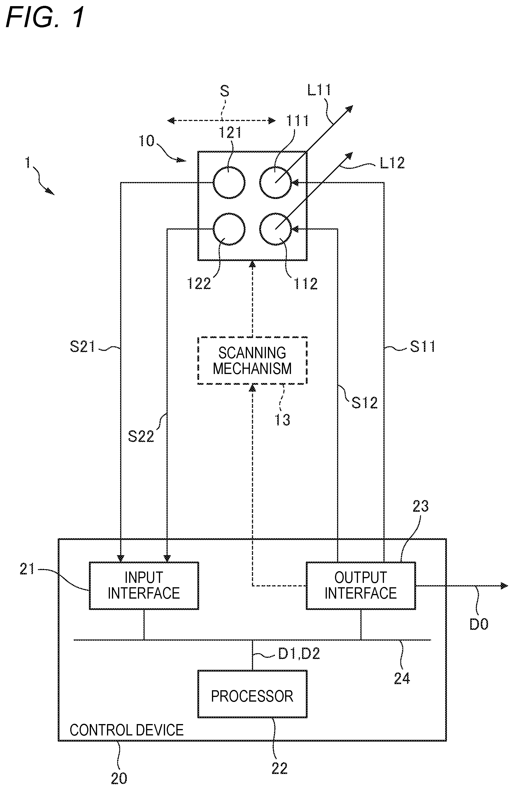
illustrates a configuration of a sensor system 1 according to a first embodiment. The sensor system 1 is installed in a vehicle.
The sensor system 1 includes a LiDAR sensor unit 10 . The LiDAR sensor unit 10 includes a first light emitting element 111 , a second light emitting element 112 , a first light receiving element 121 , and a second light receiving element 122 .
The first light emitting element 111 is configured to emit first detecting light L 11 toward the outside of the vehicle. The first detecting light L 11 is non-visible light. As the non-visible light, for example, infrared light having a wavelength of 905 nm can be used. As the first light emitting element 111 , a semiconductor light emitting element such as a laser diode or a light emitting diode can be used.
The second light emitting element 112 is configured to emit second detecting light L 12 toward the outside of the vehicle. The second detecting light L 12 is non-visible light. As the non-visible light, for example, infrared light having a wavelength of 905 nm can be used. As the second light emitting element 112 , a semiconductor light emitting element such as a laser diode or a light emitting diode can be used.
The first light receiving element 121 is configured to output a light receiving signal S 21 corresponding to the amount of incident light. The first light receiving signal S 21 is an example of the first signal. The first light receiving element 121 has sensitivity to at least the wavelength of the first detecting light L 11 . As the first light receiving element 121 , a photodiode, a phototransistor, a photo resistor, or the like can be used.
The second light receiving element 122 is configured to output a light receiving signal S 22 corresponding to the amount of incident light. The second light receiving signal S 22 is an example of the second signal. The second light receiving element 122 has sensitivity to at least the wavelength of the second detecting light L 12 . As the second light receiving element 122 , a photodiode, a phototransistor, a photo resistor, or the like can be used.
The sensor system 1 includes a control device 20 . The control device 20 includes an input interface 21 , a processor 22 , an output interface 23 , and a communication bus 24 . The input interface 21 , the processor 22 , and the output interface 23 can exchange signals and data via the communication bus 24 .
The first light receiving signal S 21 outputted from the first light receiving element 121 and the second light receiving signal S 22 outputted from the second light receiving element 122 are inputted to the input interface 21 .
The processor 22 acquires the first data D 1 and the second data D 2 respectively corresponding to the first light receiving signal S 21 and the second light receiving signal S 22 that are inputted to the input interface 21 . The first data D 1 and the second data D 2 are placed in a state that can be subjected to information processing performed in the processor 22 (described later). That is, the input interface 21 has an appropriate circuit configuration for converting the first light receiving signal S 21 and the second light receiving signal S 22 into the first data D 1 and the second data D 2 , respectively.
The processor 22 inputs the first control signal S 11 to the first light emitting element 111 via the output interface 23 , thereby controlling the light emitting operation of the first light emitting element 111 . Specifically, the amount of light, the light emission timing, the light emission cycle, and the like of the first detecting light L 11 are controlled. By appropriately performing adjustment of the light emitting timing or light modulation, identification information can be assigned to the first detecting light L 11 .
Similarly, the processor 22 inputs the second control signal S 12 to the second light emitting element 112 via the output interface 23 , thereby controlling the light emitting operation of the second light emitting element 112 . Specifically, the amount of light, the light emission timing, the light emission cycle, and the like of the second detecting light L 12 are controlled. By appropriately performing adjustment of the light emitting timing or light modulation, identification information can be assigned to the second detecting light L 12 .
As illustrated in A , the first detecting light L 11 emitted from the first light emitting element 111 is reflected by an object that situates outside the vehicle, so that first reflected light L 21 is generated. The identification information assigned to the first detecting light L 11 is reflected to the first reflected light L 21 . The first reflected light L 21 is incident on the first light receiving element 121 . The first light receiving element 121 outputs a first light receiving signal S 21 corresponding to the amount of the first reflected light L 21 . As a result, the first data D 1 associated with the first reflected light L 21 is obtained. The identification information assigned to the first detecting light L 11 is also reflected to the first data D 1 .
Similarly, the second detecting light L 12 emitted from the second light emitting element 112 is reflected by an object that situates outside the vehicle, so that second reflected light L 22 is generated. The identification information assigned to the second detecting light L 12 is reflected to the second reflected light L 22 . The second reflected light L 22 is incident on the second light receiving element 122 . The second light receiving element 122 outputs a second light receiving signal S 22 corresponding to the amount of the second reflected light L 22 . As a result, the second data D 2 associated with the second reflected light L 22 is obtained. The identification information assigned to the second detecting light L 12 is also reflected to the second data D 2 .
The processor 22 can obtain the distance to the object associated with the first reflected light L 21 based on the time period from the time when the first detecting light L 11 is emitted to the time when the first reflected light L 21 is detected. Additionally or alternatively, the processor 22 can obtain information as to an attribute such as the material of the object associated with the first reflected light L 21 based on the difference in waveforms of the first detecting light L 11 and the first reflected light L 21 .
Similarly, the processor 22 can obtain the distance to the object associated with the second reflected light L 22 based on the time period from the time when the second detecting light L 12 is emitted to the time when the second reflected light L 22 is detected. Additionally or alternatively, the processor 22 can obtain information as to an attribute such as the material of the object associated with the second reflected light L 22 based on the difference in waveforms of the second detecting light L 12 and the second reflected light L 22 .
As illustrated in , the LiDAR sensor unit 10 may include a scanning mechanism 13 . The scanning mechanism 13 changes the light emitting directions of the first detecting light L 11 and the second detecting light L 12 along a direction S intersecting the arrangement direction of the first light emitting element 111 and the second light emitting element 112 . The processor 22 can control the operation of the scanning mechanism 13 via the output interface 23 .
N sets of first data D 1 and second data D 2 are acquired by repeating the light emitting operation and the light receiving operation N times during a single scanning. For example, by acquiring the distance information to the object described above for the N sets of data, it is possible to acquire information as to the shape of the object associated with the first reflected light L 21 and the second reflected light L 22 .
The processor 22 is configured to output data DO including the information of the object that situates outside the vehicle acquired as described above via the output interface 23 to an external entity. The data DO is used for additional information processing performed by another processor.
illustrates a flow of processing performed by the processor 22 . First, the processor 22 acquires the first data D 1 and the second data D 2 as described above (STEP 1 ).
Subsequently, the processor 22 determines whether or not there is an inversion phenomenon of light reception (STEP 2 ). Specifically, it is determined whether the first data D 1 is based on the first detecting light L 11 . Similarly, it is determined whether the second data D 2 is based on the second detecting light L 12 .
As described with reference to A , in the normal state, the first reflected light L 21 generated by the first detecting light L 11 is incident on the first light receiving element 121 , and the second reflected light L 22 generated by the second detecting light L 12 is incident on the second light receiving element 122 . Accordingly, if the first data D 1 is created on the basis of the first reflected light L 21 , the identification information assigned to the first detecting light L 11 is reflected in the first data D 1 . If the second data D 2 is created on the basis of the second reflected light L 22 , the identification information assigned to the second detecting light L 12 is reflected in the second data D 2 . The processor 22 makes the above-described determination through the detection of the identification information.
When it is determined that the first data D 1 is based on the first detecting light L 11 and the second data D 2 is based on the second detecting light L 12 (N in STEP 2 of ), the first data D 1 and the second data D 2 are outputted as they are as illustrated in A (STEP 3 of ). Thereafter, the processing returns to STEP 1 .
As illustrated in B , when the LiDAR sensor unit 10 is displaced due to vibration or the like of the vehicle, the first reflected light L 21 may happen to be incident on the second light receiving element 122 and the second reflected light L 22 may happen to be incident on the first light receiving element 121 . In this case, the identification information assigned to the second detecting light L 12 is reflected in the first data D 1 created on the basis of the first light receiving signal S 21 outputted from the first light receiving element 121 . On the other hand, the identification information assigned to the first detecting light L 11 is reflected in the second data D 2 created on the basis of the second light receiving signal S 22 outputted from the second light receiving element 122 . When the first data D 1 and the second data D 2 are outputted as they are, the accuracy of the information as for the object in an outside area of the vehicle that is to be obtained by the subsequent processing is reduced.
Accordingly, when it is determined that the first data D 1 is based on the second detecting light L 12 and the second data D 2 is based on the second detecting light L 12 (Y in STEP 2 of ), the processor 22 performs processing for exchanging the first data D 1 and the second data D 2 , as illustrated in B (STEP 4 of ). Subsequently, the first data D 1 and the second data D 2 that have been exchanged are outputted (STEP 3 of ). For example, when the first data D 1 and the second data D 2 are serially outputted, the order of outputting the first data D 1 and the second data D 2 is exchanged. For example, when the first data D 1 and the second data D 2 are outputted in parallel, the addresses of the output ports assigned to both data are exchanged.
When N light emitting operations and light receiving operations are performed during a single scanning while the light emitting directions of the first detecting light L 11 and the second detecting light L 12 are changed by the scanning mechanism 13 , a data set of 2 rows×N columns (a set including N first data D 1 and N second data D 2 ) is acquired. In this case, the exchange of the first data D 1 and the second data D 2 may be performed in units of rows. That is, the entire N pieces of first data D 1 and the entire N pieces of second data D 2 can be exchanged with each other.
According to such a configuration, even when reflected light from an object is not normally incident on the light receiving element due to vibration or the like of the vehicle, it is possible to output data corresponding to a normal light receiving state. In a sensor system including at least two sets of light emitting elements and light receiving elements, it is possible to suppress degradation in information processing capability caused by vibration or the like of the vehicle.
In the present embodiment, the first light receiving element 121 and the second light receiving element 122 are arranged in a direction corresponding to an up-down direction of the vehicle.
The vibration of the vehicle is dominated by a component in the up-down direction. Accordingly, the above-described inversion phenomenon of light reception is likely to occur between the first light receiving element 121 and the second light receiving element 122 arranged in the direction corresponding to the up-down direction of the vehicle. However, since the processor 22 can exchange the first data D 1 and the second data D 2 as described above, it is possible to effectively correct the influence of the inversion phenomenon in the light reception caused by the vibration of the vehicle.
illustrates another exemplary configuration of the sensor system 1 . The LiDAR sensor unit 10 according to the present example further includes a third light emitting element 113 and a third light receiving element 123 .
The third light emitting element 113 is disposed between the first light emitting element 111 and the second light emitting element 112 . The third light emitting element 113 is configured to emit third detecting light L 13 toward the outside of the vehicle. The third detecting light L 13 is non-visible light. As the non-visible light, for example, infrared light having a wavelength of 905 nm can be used. As the third light emitting element 113 , a semiconductor light emitting element such as a laser diode or a light emitting diode can be used.
The third light receiving element 123 is disposed between the first light receiving element 121 and the second light receiving element 122 . The third light receiving element 123 is configured to output a light receiving signal S 1 corresponding to the amount of incident light. The third light receiving signal S 23 is an example of the third signal. The third light receiving element 123 has sensitivity to at least the wavelength of the third detecting light L 13 . As the third light receiving element 123 , a photodiode, a phototransistor, a photo resistor, or the like can be used.
The third light receiving signal S 23 outputted from the third light receiving element 123 is inputted to the input interface 21 of the control device 20 . The processor 22 acquires the third data D 3 corresponding to the third light receiving signal S 23 inputted to the input interface 21 . The third data D 3 is placed in a state that can be subjected to information processing performed in the processor 22 (described later). That is, the input interface 21 has an appropriate circuit configuration for converting the third light receiving signal S 23 into the third data D 3 .
The processor 22 inputs the third control signal S 13 to the third light emitting element 113 via the output interface 23 , thereby controlling the light emitting operation of the third light emitting element 113 . Specifically, the amount of light, the light emission timing, the light emission cycle, and the like of the third detecting light L 13 are controlled. By appropriately performing adjustment of the light emitting timing or light modulation, identification information can be assigned to the third detecting light L 13 .
As illustrated in A , the third detecting light L 13 emitted from the third light emitting element 113 is reflected by an object that situates outside the vehicle, so that third reflected light L 23 is generated. The identification information assigned to the third detecting light L 13 is reflected to the third reflected light L 23 . The third reflected light L 23 is incident on the third light receiving element 123 . The third light receiving element 123 outputs a third light receiving signal S 23 corresponding to the amount of the third reflected light L 23 . As a result, the third data D 3 associated with the third reflected light L 23 is obtained. The identification information assigned to the third detecting light L 13 is also reflected to the third data D 3 .
The processor 22 can obtain the distance to the object associated with the third reflected light L 23 based on the time period from the time when the third detecting light L 13 is emitted to the time when the third reflected light L 23 is detected. Additionally or alternatively, the processor 22 can obtain information as to an attribute such as the material of the object associated with the third reflected light L 23 based on the difference in waveforms of the third detecting light L 13 and the third reflected light L 23 .
As illustrated in , the LiDAR sensor unit 10 may include a scanning mechanism 13 . The scanning mechanism 13 changes the light emitting directions of the first detecting light L 11 , the second detecting light L 12 , and the third detecting light L 3 along a direction S intersecting the arrangement direction of the first light emitting element 111 , the second light emitting element 112 , and the third light emitting element 113 . The processor 22 can control the operation of the scanning mechanism 13 via the output interface 23 .
N sets of first data D 1 , second data D 2 , and third data D 3 are acquired by repeating the light emitting operation and the light receiving operation N times during a single scanning. For example, by acquiring the distance information to the object described above for the N sets of data, it is possible to acquire information as to the shape of the object associated with the first reflected light L 21 , the second reflected light L 22 , and the third reflected light L 23 .
The processor 22 is configured to output data DO including the information of the object that situates outside the vehicle acquired as described above via the output interface 23 to an external entity. The data DO is used for additional information processing performed by another processor.
The operations performed by the processor 22 according to the present example can also be described in the flowchart illustrated in . First, the processor 22 acquires the first data D 1 , the second data D 2 , and the third data D 3 as described above (STEP 1 ).
Subsequently, the processor 22 determines whether or not there is an inversion phenomenon of light reception (STEP 2 ). The determination is made between the first data D 1 and the third data D 3 , as well as between the third data D 3 and the second data D 2 . For example, when it is determined that the first data D 1 is based on the third detecting light L 13 and the third data D 3 is based on the first detecting light L 11 (Y in STEP 2 ), the first data D 1 and the third data D 3 are exchanged (STEP 4 ).
In this example, when it is determined that no inversion phenomenon is occurred in the light reception (N in STEP 2 ), it is determined whether or not an overlap phenomenon is occurred in the light reception (STEPS). Specifically, it is determined whether both the first data D 1 and the third data D 3 are based on the first detecting light L 11 or the third detecting light L 13 . Similarly, it is determined whether both the third data D 3 and the second data D 2 are based on the third detecting light L 13 or the second detecting light L 12 .
As described with reference to A , in the normal state, the first reflected light L 21 generated by the first detecting light L 11 is incident on the first light receiving element 121 , the second reflected light L 22 generated by the second detecting light L 12 is incident on the second light receiving element 122 , and the third reflected light L 23 generated by the third detecting light L 13 is incident on the third light receiving element 123 . Accordingly, if the first data D 1 is created on the basis of the first reflected light L 21 , the identification information assigned to the first detecting light L 11 is reflected in the first data D 1 . If the second data D 2 is created on the basis of the second reflected light L 22 , the identification information assigned to the second detecting light L 12 is reflected in the second data D 2 . If the third data D 3 is created on the basis of the third reflected light L 23 , the identification information assigned to the third detecting light L 13 is reflected in the third data D 3 . The processor 22 makes the above-described determination through the detection of the identification information.
When it is determined that the first data D 1 is based on the first detecting light L 11 , the second data D 2 is based on the second detecting light L 12 , and the third data D 3 is based on the third detecting light L 13 (N in STEPS of ), the first data D 1 , the second data D 2 , and the third data D 3 are outputted as they are, as illustrated in A (STEP 3 of ). Thereafter, the processing returns to STEP 1 .
As illustrated in B , when the LiDAR sensor unit 10 is displaced due to vibration or the like of the vehicle, the third reflected light L 23 may happen to be incident on both the first light receiving element 121 and the third light receiving element 123 . In this case, the identification information assigned to the third detecting light L 13 is reflected in the first data D 1 created on the basis of the first light receiving signal S 21 outputted from the first light receiving element 121 . Similarly, the identification information assigned to the third detecting light L 13 is also reflected in the third data D 3 created on the basis of the third light receiving signal S 23 outputted from the third light receiving element 123 . When the first data D 1 and the third data D 3 are outputted as they are, the accuracy of the information as for the object in an outside area of the vehicle that is to be obtained by the subsequent processing is reduced.
Accordingly, when it is determined that both the first data D 1 and the third data D 3 are based on the first detecting light L 11 or the third detecting light L 13 , or when it is determined that both the second data D 2 and the third data D 3 are based on the second detecting light L 12 or the third detecting light L 13 (Y in STEPS of ), the processor 22 performs processing for replacing the third data D 3 with average data DA, as illustrated in B (STEP 6 of ). The average data DA is created by averaging the first data D 1 and the second data D 2 .
If only one set of the first data D 1 , the second data D 2 , and the third data D 3 are acquired, the averaging processing is processing for calculating a simple average of the first data D 1 and the second data D 2 . In a case where a plurality of sets of the first data D 1 , the second data D 2 , and the third data D 3 are acquired by using the scanning mechanism 13 , the averaging processing may be any of calculation of a simple average, calculation of a median value, and calculation of a mode value.
Subsequently, the replaced first data D 1 , the second data D 2 , and the average data DA are outputted (STEP 3 of ).
According to such a configuration, even when reflected light from an object is not normally incident on the light receiving element due to vibration or the like of the vehicle, it is possible to output data similar to the data that shall be obtained in the normal light receiving state. Accordingly, in a sensor system including at least three sets of light emitting elements and light receiving elements, it is possible to suppress degradation in information processing capability caused by vibration or the like of the vehicle.
In the present embodiment, the first light receiving element 121 , the second light receiving element 122 , and the third light receiving element 123 are arranged in a direction corresponding to the up-down direction of the vehicle.
The vibration of the vehicle is dominated by a component in the up-down direction. Accordingly, the above-described overlap phenomenon of light reception is likely to occur among the first light receiving element 121 , the second light receiving element 122 , and the third light receiving element 123 arranged in the direction corresponding to the up-down direction of the vehicle. However, since the processor 22 can perform the above-described averaging processing, it is possible to effectively correct the influence of the overlap phenomenon in the light reception caused by the vibration of the vehicle.
The functions of the processor 22 described later may be realized by a general-purpose microprocessor cooperating with a memory, or may be realized by a dedicated integrated circuit such as a microcontroller, an FPGA, and an ASIC.
The control device 20 may be disposed at any position in the vehicle. The control device 20 may be implemented by a main ECU configured to perform central control processing in the vehicle, or may be implemented by a sub ECU interposed between the main ECU and the LiDAR sensor unit 10 .
The above embodiments are mere examples for facilitating understanding of the presently disclosed subject matter. The configuration according to the above embodiment can be appropriately modified without departing from the gist of the presently disclosed subject matter.
In the above embodiment, the first light emitting element 111 and the second light emitting element 112 are arranged in the direction corresponding to the up-down direction of the vehicle. The first light receiving element 121 and the second light receiving element 122 are also arranged in the direction corresponding to the up-down direction of the vehicle. However, the first light emitting element 111 and the second light emitting element 112 may be arranged in a direction corresponding to a left-right direction or a front-rear direction of the vehicle. The first light receiving element 121 and the second light receiving element 122 may also be arranged in the direction corresponding to the left-right direction or the front-rear direction of the vehicle. In this case, the light emitting directions of the first detecting light L 11 and the second detecting light L 12 can be changed by the scanning mechanism 13 in the direction corresponding to the up-down direction of the vehicle.
The LiDAR sensor unit 10 may be replaced with an appropriate sensor unit capable of detecting information in an outside area of the vehicle using a light emitting element and a light receiving element. Examples of such a sensor unit may include a TOF camera unit and a millimeter wave radar unit. A configuration using plural types of measurement techniques may be incorporated in a single sensor unit. The wavelength of the detecting light emitted by the light emitting element and the wavelength at which the light receiving element has sensitivity can be appropriately determined according to the detection technique to be used.
schematically illustrates a configuration of a sensor system 2 according to a second embodiment. The sensor system 2 is installed in a vehicle.
The sensor system 2 includes a LiDAR sensor unit 30 . The LiDAR sensor 30 includes a light emitting element 31 and a light receiving element 32 .
The light emitting element 31 is configured to emit detecting light L 1 toward the outside of the vehicle. The detecting light L 1 is non-visible light. As the non-visible light, for example, infrared light having a wavelength of 905 nm can be used. As the light emitting element 31 , a semiconductor light emitting element such as a laser diode or a light emitting diode can be used.
The light receiving element 32 is configured to output a light receiving signal S 1 corresponding to the amount of incident light. The light receiving element 32 has sensitivity to at least the wavelength of the detecting light L 1 . As the light receiving element 32 , a photodiode, a phototransistor, a photo resistor, or the like can be used.
The sensor system 2 includes a control device 40 . The control device 40 includes an input interface 41 , a processor 42 , an output interface 43 , and a communication bus 44 . The input interface 41 , the processor 42 , and the output interface 43 can exchange signals and data via the communication bus 44 .
The light receiving signal S 1 outputted from the light receiving element 32 is inputted to the input interface 41 . The processor 42 acquires light receiving data D 11 corresponding to the light reception signal S 1 inputted to the input interface 41 . The light receiving data D 11 is placed in a state that can be subjected to information processing performed in the processor 42 (described later). That is, the input interface 41 has an appropriate circuit configuration for converting the light receiving signal S 1 into the light receiving data D 11 .
The processor 42 inputs a control signal SO to the light emitting element 31 via the output interface 43 , thereby controlling the light emitting operation of the light emitting element 31 . Specifically, the amount of light, the light emission timing, the light emission cycle, and the like of the detecting light L 1 are controlled.
The detecting light L 1 emitted from the light emitting element 31 is reflected by an object that situates outside the vehicle, so that reflected light L 2 is generated. The reflected light L 2 is incident on the light receiving element 32 . The light receiving element 32 outputs a light receiving signal S 1 corresponding to the amount of light of the reflected light L 2 . As a result, the light receiving data D 11 associated with the reflected light L 2 is obtained. The light receiving data D 11 is an example of data corresponding to information in an outside area of the vehicle.
The processor 42 can obtain the distance to the object associated with the reflected light L 2 based on the time period from the time when the detecting light L 1 is emitted to the time when the reflected light L 2 is detected. Additionally or alternatively, the processor 130 can obtain information as to an attribute such as the material of the object associated with the reflected light L 2 based on the difference in waveforms of the detecting light L 1 and the reflected light L 2 .
The LiDAR sensor unit 30 may include a scanning mechanism 33 . The scanning mechanism 33 changes the light emitting direction of the detecting light L 1 , for example, along a direction S intersecting the up-down direction of the vehicle. The processor 42 can control the operation of the scanning mechanism 33 via the output interface 43 .
N first data D 1 are acquired by repeating the light emitting operation and the light receiving operation N times during a single scanning. For example, by acquiring the distance information to the object described above for the N data sets, it is possible to acquire information as to the shape of the object associated with the reflected light L 2 .
The processor 42 is configured to output data D 10 including the information of the object that situates outside the vehicle acquired as described above via the output interface 43 to an external entity. The data D 10 is used for additional information processing performed by another processor.
The sensor system 2 includes a displacement sensor 50 . The displacement sensor 50 is configured to detect the displacement of the LiDAR sensor unit 30 . The displacement sensor 50 may be implemented by an acceleration sensor or a gyro sensor. The displacement sensor 50 is configured to output a displacement signal S 2 corresponding to the detected LiDAR sensor unit 30 .
The displacement signal S 2 outputted from the displacement sensor 50 is inputted to the input interface 41 of the control device 40 . The processor 42 acquires displacement data D 12 corresponding to the displacement signal S 2 inputted to the input interface 41 . The displacement data D 12 is placed in a state that can be subjected to information processing performed in the processor 42 (described later). That is, the input interface 41 has an appropriate circuit configuration for converting the displacement signal S 2 into the displacement data D 12 .
An area A 1 illustrated in A illustrates an information detectable area of the LiDAR sensor unit 30 . The area A 2 represents an area including information outputted as the above-described data D 10 . The processor 42 extracts a portion corresponding to the area A 2 from the acquired light receiving data D 11 to create the data D 10 .
Due to vibration of the vehicle or the like, the LiDAR sensor unit 30 may be displaced from the initial position indicated by dashed lines. In the example illustrated in B , the LiDAR sensor unit 30 is displaced in the upper right direction, and the area A 1 is also displaced in the upper right direction. As a result, the position of the object to be detected moves in the left-lower direction within the area A 2 . If no countermeasure is taken, there would be a case where information such as the distance to the object cannot be accurately obtained.
The displacement of the LiDAR sensor unit 30 is detected by the displacement sensor 50 . Based on the displacement data D 12 corresponding to the displacement, the processor 42 changes the area A 2 to a position where the displacement of the LiDAR sensor unit 30 can be compensated for. In the example illustrated in B , the area A 2 is moved from the initial position indicated by solid lines to the correction position indicated by chain lines. Such a changing processing is an example of correction of the light receiving data D 11 based on the displacement data D 12 . The D 10 is created from the light receiving data D 11 corresponding to the area A 2 the position of which has been changed in this manner, and outputted through the output interface 43 .
According to the configuration as described above, it is possible to suppress the influence of the displacement of the LiDAR sensor unit 30 caused by the vibration or the like of the vehicle on the information detection. Accordingly, it is possible to suppress degradation in the information acquisition capability of the sensor system 2 caused by vibration or the like of the vehicle.
The functions of the processor 42 described later may be realized by a general-purpose microprocessor cooperating with a memory, or may be realized by a dedicated integrated circuit such as a microcontroller, an FPGA, and an ASIC.
The control device 40 may be disposed at any position in the vehicle. The control device 40 may be implemented by a main ECU configured to perform central control processing in the vehicle, or may be implemented by a sub ECU interposed between the main ECU and the LiDAR sensor unit 30 .
The above embodiments are mere examples for facilitating understanding of the presently disclosed subject matter. The configuration according to the above embodiment can be appropriately modified without departing from the gist of the presently disclosed subject matter.
The displacement direction of the LiDAR sensor unit 30 detectable by the displacement sensor 50 is appropriately determined so as to include a pitch direction, a yaw direction, a roll direction, a horizontal shift direction, and a vertical shift direction. Since the vibration of the vehicle is dominated by a component in the up-down direction, it is preferable that the displacement sensor 50 is configured to be capable of detecting the displacement of the LiDAR sensor unit 30 at least along the up-down direction of the vehicle.
The LiDAR sensor unit 30 may be replaced with an appropriate sensor unit capable of detecting information in an outside area of the vehicle using a light emitting element and a light receiving element. Examples of such a sensor unit may include a TOF camera unit and a millimeter wave radar unit. A configuration using plural types of measurement techniques may be incorporated in a single sensor unit. The wavelength of the detecting light emitted by the light emitting element and the wavelength at which the light receiving element has sensitivity can be appropriately determined according to the detection technique to be used.
Figures (7)
Citations
This patent cites (33)
- US5652655
- US20070076186
- US20140009747
- US20150316650
- US20160164258
- US20160222714
- US20170199272
- US20170254697
- US20180284256
- US20180329064
- US20180348369
- US20190011567
- US20190250263
- US101246000
- US103983195
- US105579870
- US106471335
- US107152913
- US107850668
- US108139476
- US108139477
- US8-248133
- US9-96525
- US2697307
- US10-209838
- US2007-101342
- US2008-185563
- US2010-185769
- US2013-113698
- US2014-29317
- US2016-525802
- US2017-166846
- US2014/038527