Inflatable with Elastic Constraint Tethers
Abstract
An inflatable structure includes a top end cap, a bottom end cap, a bladder attached to the top and bottom end caps and configured to hold pressurized air therebetween, and a plurality of tethers disposed within the bladder, each tether in the plurality of tethers having a first end coupled to the top end cap and a second end coupled to the bottom end cap, wherein when the bladder is inflated, the bladder expands axially forcing the top end cap and the bottom end cap away from one another, the plurality of tethers adapted to restrict movement of the top end cap and the bottom end cap away from one another and limit axial expansion of the bladder, wherein, at least one of the plurality of tethers is elastic, and the inflatable structure is adapted to provide multiple support profiles that are capable of supporting compressive loading.
Claims (20)
1. An inflatable structure comprising: a top end cap; a bottom end cap; a bladder attached to the top and bottom end caps and configured to hold pressurized air between the top and bottom end caps; a plurality of tethers disposed within the bladder, each tether in the plurality of tethers having a first end coupled to the top end cap and a second end coupled to the bottom end cap, wherein when the bladder is inflated, the bladder expands axially forcing the top end cap and the bottom end cap away from one another, the plurality of tethers adapted to restrict movement of the top end cap and the bottom end cap away from one another and limit axial expansion of the bladder, at least one of the plurality of tethers having an ultimate length that is different than an ultimate length of the remaining of the plurality of tethers; wherein, at least one of the plurality of tethers is elastic, and the inflatable structure is adapted to provide multiple support profiles that are capable of supporting compressive loading.
16. An inflatable structure comprising: a top end cap; a bottom end cap; a bladder attached to the top and bottom end caps and configured to hold pressurized air between the top and bottom end caps; a plurality of tethers disposed within the bladder, each tether in the plurality of tethers having a first end coupled to the top end cap and a second end coupled to the bottom end cap, wherein when the bladder is inflated, the bladder expands axially forcing the top end cap and the bottom end cap away from one another, the plurality of tethers adapted to restrict movement of the top end cap and the bottom end cap away from one another and limit axial expansion of the bladder, at least one of the plurality of tethers having an ultimate length that is different that an ultimate length of the remaining of the plurality of tethers, and all of the plurality of tethers have an equal stiffness; wherein, at least one of the plurality of tethers is elastic, and the inflatable structure includes a final support profile, wherein all of the plurality of tethers are extended to an ultimate length, and at least one intermediate support profile, wherein at least one of the plurality of tethers is not extended to an ultimate length.
Show 18 dependent claims
2. The inflatable structure of claim 1 , wherein the inflatable structure includes a final support profile, wherein all of the plurality of tethers are extended to an ultimate length, and at least one intermediate support profile, wherein at least one of the plurality of tethers is not extended to an ultimate length.
3. The inflatable structure of claim 2 , wherein the at least one elastic tether comprises one of: an elastic band; a spring; and an elastic core surrounded by an inelastic outer winding.
4. The inflatable structure of claim 2 , wherein one of the plurality of tethers has an ultimate length that is greater than an ultimate length of the remaining of the plurality of tethers.
5. The inflatable structure of claim 4 , wherein, all of the plurality of tethers are elastic and have an equal stiffness.
6. The inflatable structure of claim 2 , wherein at least one of the plurality of tethers is pre-tensioned.
7. The inflatable structure of claim 2 , wherein at least one of the plurality of tethers has a stiffness that is different than a stiffness of the remaining of the plurality of tethers.
8. The inflatable structure of claim 2 , wherein all of the plurality of tethers have an equal stiffness.
9. The inflatable structure of claim 8 , wherein at least one of the plurality of tethers is pre-tensioned.
10. The inflatable structure of claim 2 , wherein at least one of the plurality of tethers includes a first tether segment and a second tether segment, the first and second tether segments attached to one another end to end.
11. The inflatable structure of claim 10 , wherein the first tether segment has a stiffness that is different than a stiffness of the second tether segment.
12. The inflatable structure of claim 11 , wherein only one of the first tether segment and the second tether segment is elastic.
13. The inflatable structure of claim 10 , wherein the first tether segment has an ultimate length that is different than an ultimate length of the second tether segment.
14. The inflatable structure of claim 10 , wherein one of the first tether segment and the second tether segment is pre-tensioned.
15. The inflatable structure of claim 2 , wherein an orientation of the top end cap when the inflatable structure is in the final support profile is different than an orientation of the top end cap when the inflatable structure is in the at least one intermediate support profile.
17. The inflatable structure of claim 16 , wherein the at least one elastic tether comprises one of: an elastic band; a spring; and an elastic core surrounded by an inelastic outer winding.
18. The inflatable structure of claim 16 , wherein at least one of the plurality of tethers has an ultimate length that is greater than an ultimate length of the remaining of the plurality of tethers, and all of the plurality of tethers are elastic and have an equal stiffness.
19. The inflatable structure of claim 18 , wherein the at least one elastic tether includes a first tether segment and a second tether segment, the first and second tether segments attached to one another end to end, at least one of the first tether segment and the second tether segment being elastic, the first tether segment having a stiffness that is different than a stiffness of the second tether segment, and the first tether segment having an ultimate length that is different than an ultimate length of the second tether segment.
20. The inflatable structure of claim 16 , wherein all of the plurality of tethers have an equal ultimate length, and one of: at least one of the plurality of tethers has a stiffness that is different than a stiffness of the remaining of the plurality of tethers; and all of the plurality of tethers have an equal stiffness, and at least one of the plurality of tethers is pre-tensioned.
Full Description
Show full text →
INTRODUCTION
The present disclosure relates to inflatable structures that provide multiple support structures.
Internally tensioned inflatable structures typically include a bladder that holds pressurized air and tethers that are attached to opposite internal surfaces of the bladder. As the bladder is inflated, the pressure within the bladder causes the bladder to expand outward and thereby, ultimately applies tension to the tethers, which in turn limits expansion of the bladder. In addition to limiting expansion of the bladder, the tethers increase the amount of compressive load that the bladder may withstand before the bladder deforms due to the compressive load.
In known inflatable structures, when the bladder is not inflated, there is no tension on the tethers and the tethers are slack. When pressure is applied within the bladder, the bladder begins to expand. The bladder does not need to overcome any resistance to expansion, and any pressure above atmospheric will cause the bladder to expand. Because there is no resistance to expansion, the pressure within the bladder does not increase substantially until the bladder is fully inflated. Thus, the bladder is incapable of supporting any significant load until the bladder is fully expanded. Once the bladder is fully expanded, and the tethers are tensioned, pressure can build up within the bladder such that the bladder is capable of supporting load. The higher the pressure within the bladder, the more compressive loading the bladder is capable of supporting before the bladder deforms due to the compressive load.
Thus, while current inflatable structures achieve their intended purpose, there is a need for a new and improved inflatable structure that includes at least one elastic tether and is capable of providing multiple support profiles that are capable of supporting compressive loads.
SUMMARY
According to several aspects of the present disclosure, an inflatable structure includes a top end cap, a bottom end cap, a bladder attached to the top and bottom end caps and configured to hold pressurized air between the top and bottom end caps, and a plurality of tethers disposed within the bladder, each tether in the plurality of tethers having a first end coupled to the top end cap and a second end coupled to the bottom end cap, wherein when the bladder is inflated, the bladder expands axially forcing the top end cap and the bottom end cap away from one another, the plurality of tethers adapted to restrict movement of the top end cap and the bottom end cap away from one another and limit axial expansion of the bladder, wherein, at least one of the plurality of tethers is elastic, and the inflatable structure is adapted to provide multiple support profiles that are capable of supporting compressive loading.
According to another aspect, the inflatable structure includes a final support profile, wherein all of the plurality of tethers are extended to an ultimate length, and at least one intermediate support profile, wherein at least one of the plurality of tethers is not extended to an ultimate length.
According to another aspect, the at least one elastic tether comprises one of an elastic band, a spring, and an elastic core surrounded by an inelastic outer winding.
According to another aspect, at least one of the plurality of tethers has an ultimate length that is different than an ultimate length of the remaining of the plurality of tethers.
According to another aspect, all of the plurality of tethers are elastic and have an equal stiffness.
According to another aspect, all of the plurality of tethers have an equal ultimate length.
According to another aspect, at least one of the plurality of tethers has a stiffness that is different than a stiffness of the remaining of the plurality of tethers.
According to another aspect, all of the plurality of tethers have an equal stiffness.
According to another aspect, at least one of the plurality of tethers is pre-tensioned.
According to another aspect, the at least one elastic tether includes a first segment and a second segment, the first and second tether segments attached to one another end to end.
According to another aspect, the first tether segment has a stiffness that is different than a stiffness of the second tether segment.
According to another aspect, only one of the first segment and the second segment is elastic.
According to another aspect, the first tether segment has an ultimate length that is different than an ultimate length of the second tether segment.
According to another aspect, one of the first tether and the second tether is pre-tensioned.
According to another aspect, an orientation of the top end cap when the inflatable structure is in the final support profile is different than an orientation of the top end cap when the inflatable structure is in the at least one intermediate support profile.
According to several aspects of the present disclosure, an inflatable structure includes a top end cap, a bottom end cap, a bladder attached to the top and bottom end caps and configured to hold pressurized air between the top and bottom end caps, and a plurality of tethers disposed within the bladder, each tether in the plurality of tethers having a first end coupled to the top end cap and a second end coupled to the bottom end cap, wherein when the bladder is inflated, the bladder expands axially forcing the top end cap and the bottom end cap away from one another, the plurality of tethers adapted to restrict movement of the top end cap and the bottom end cap away from one another and limit axial expansion of the bladder, wherein, at least one of the plurality of tethers is elastic, and the inflatable structure includes a final support profile, wherein all of the plurality of tethers are extended to an ultimate length, and at least one intermediate support profile, wherein at least one of the plurality of tethers is not extended to an ultimate length.
According to another aspect, at least one of the plurality of tethers has an ultimate length that is different that an ultimate length of the remaining of the plurality of tethers, and all of the plurality of tethers are elastic and have an equal stiffness.
According to another aspect, all of the plurality of tethers have an equal ultimate length, and one of at least one of the plurality of tethers has a stiffness that is different than a stiffness of the remaining of the plurality of tethers, and all of the plurality of tethers have an equal stiffness, and at least one of the plurality of tethers is pre-tensioned.
According to another aspect, the at least one elastic tether includes a first tether segment and a second tether segment, the first and second tether segments attached to one another end to end, at least one of the first tether segment and the second tether segment being elastic, the first tether segment having a stiffness that is different than a stiffness of the second tether segment, and the first tether segment having an ultimate length that is different than an ultimate length of the second tether segment.
Further areas of applicability will become apparent from the description provided herein. It should be understood that the description and specific examples are intended for purposes of illustration only and are not intended to limit the scope of the present disclosure.
BRIEF DESCRIPTION OF THE DRAWINGS
The drawings described herein are for illustration purposes only and are not intended to limit the scope of the present disclosure in any way.
A is a schematic view of an inflatable structure in accordance with an exemplary embodiment including first and second tethers that have equal stiffness and different ultimate lengths;
B is a schematic view of the inflatable structure shown in A , wherein the bladder is pressurized to one psi;
C is a schematic view of the inflatable structure shown in A , wherein the bladder is pressurized to five psi;
D is a schematic view of the inflatable structure shown in A , wherein the bladder is pressurized to seven psi;
E is a schematic view of the inflatable structure shown in A , wherein the bladder is pressurized to nine psi;
is a graph plotting the length of the first and second tethers vs. the pressure within the bladder for the inflatable structure shown in A ;
A is a schematic view of an inflatable structure in accordance with an exemplary embodiment including first, second and third tethers that have equal stiffness and different ultimate lengths;
B is a schematic view of the inflatable structure shown in A , wherein the bladder is pressurized to five psi;
C is a schematic view of the inflatable structure shown in A , wherein the bladder is pressurized to seven psi;
D is a schematic view of the inflatable structure shown in A , wherein the bladder is pressurized to ten psi;
A is a schematic view of an inflatable structure in accordance with an exemplary embodiment including first and second tethers that have different stiffness and equal ultimate lengths;
B is a schematic view of the inflatable structure shown in A , wherein the bladder is pressurized to four psi;
C is a schematic view of the inflatable structure shown in A , wherein the bladder is pressurized to five psi;
D is a schematic view of the inflatable structure shown in A , wherein the bladder is pressurized to seven psi;
E is a schematic view of the inflatable structure shown in A , wherein the bladder is pressurized to eight psi;
is a graph plotting the length of the first and second tethers vs. the pressure within the bladder for the inflatable structure shown in A ;
A is a schematic view of an inflatable structure in accordance with an exemplary embodiment including first and second tethers that have equal stiffness and equal ultimate lengths;
B is a schematic view of the inflatable structure shown in A , wherein the bladder is pressurized to five psi;
C is a schematic view of the inflatable structure shown in A , wherein the bladder is pressurized to ten psi;
A is a schematic view of an inflatable structure in accordance with an exemplary embodiment including first and second tethers that are pre-tensioned;
B is a schematic view of the inflatable structure shown in A , wherein the bladder is pressurized to one psi;
C is a schematic view of the inflatable structure shown in A , wherein the bladder is pressurized to five psi;
D is a schematic view of the inflatable structure shown in A , wherein the bladder is pressurized to greater than seven psi;
E is a schematic view of the inflatable structure shown in A , wherein the bladder is pressurized to nine psi;
is a graph plotting the length of the first and second tethers vs. the pressure within the bladder for the inflatable structure shown in A ;
A is a schematic view of an inflatable structure in accordance with an exemplary embodiment including first and second tethers that each include first and second segments attached end to end;
B is a schematic view of the inflatable structure shown in A , wherein the bladder is pressurized to one psi;
C is a schematic view of the inflatable structure shown in A , wherein the bladder is pressurized to five psi;
D is a schematic view of the inflatable structure shown in A , wherein the bladder is pressurized to greater than seven psi;
E is a schematic view of the inflatable structure shown in A , wherein the bladder is pressurized to nine psi; and
is a graph plotting the length of the first and second tethers vs. the pressure within the bladder for the inflatable structure shown in A .
The figures are not necessarily to scale and some features may be exaggerated or minimized, such as to show details of particular components. In some instances, well-known components, systems, materials or methods have not been described in detail in order to avoid obscuring the present disclosure. Therefore, specific structural and functional details disclosed herein are not to be interpreted as limiting, but merely as a basis for the claims and as a representative basis for teaching one skilled in the art to variously employ the present disclosure.
DETAILED DESCRIPTION
The following description is merely exemplary in nature and is not intended to limit the present disclosure, application, or uses. Furthermore, there is no intention to be bound by any expressed or implied theory presented in the preceding technical field, background, brief summary or the following detailed description. It should be understood that throughout the drawings, corresponding reference numerals indicate like or corresponding parts and features. As used herein, the term module refers to any hardware, software, firmware, electronic control component, processing logic, and/or processor device, individually or in any combination, including without limitation: application specific integrated circuit (ASIC), an electronic circuit, a processor (shared, dedicated, or group) and memory that executes one or more software or firmware programs, a combinational logic circuit, and/or other suitable components that provide the described functionality. Although the figures shown herein depict an example with certain arrangements of elements, additional intervening elements, devices, features, or components may be present in actual embodiments. It should also be understood that the figures are merely illustrative and may not be drawn to scale.
As used herein, the term “vehicle” is not limited to automobiles. While the present technology is described primarily herein in connection with automobiles, the technology is not limited to automobiles. The concepts can be used in a wide variety of applications, such as in connection with aircraft, marine craft, other vehicles, and consumer electronic components.
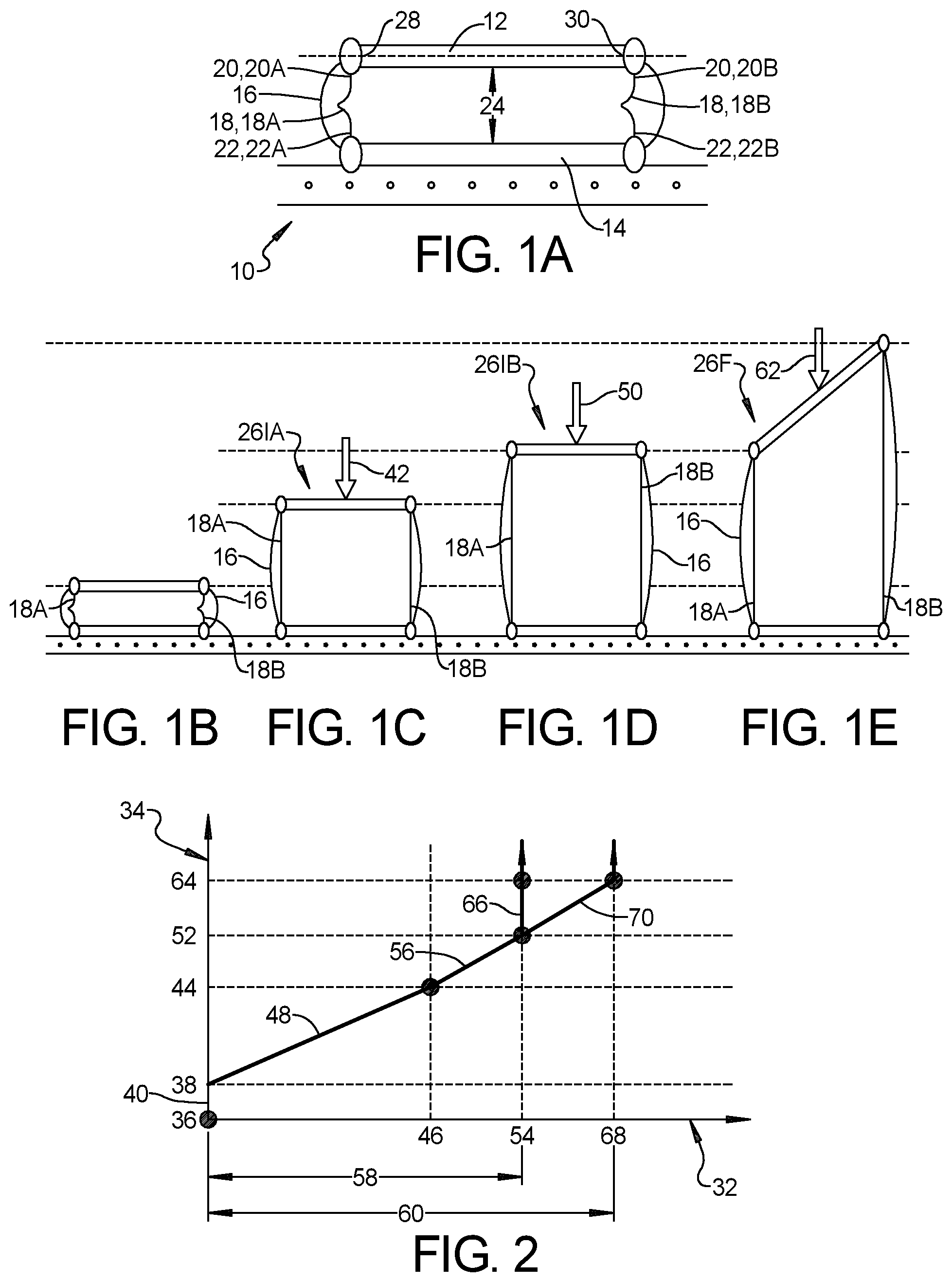
Referring to A through E , an inflatable structure 10 in accordance with the present disclosure includes a top end cap 12 , a bottom end cap 14 , a bladder 16 attached to the top and bottom end caps 12 , 14 and configured to hold pressurized air between the top and bottom end caps 12 , 14 , and a plurality of tethers 18 disposed within the bladder 16 . Each tether 18 in the plurality of tethers 18 has a first end 20 coupled to the top end cap 12 and a second end 22 coupled to the bottom end cap 14 . When the bladder 16 is inflated, the bladder 16 expands axially, as indicated by arrow 24 , forcing the top end cap 12 and the bottom end cap 14 away from one another. The plurality of tethers 18 are adapted to restrict movement of the top end cap 12 and the bottom end cap 14 away from one another and limit axial expansion of the bladder 16 . At least one of the plurality of tethers 18 is elastic, and the inflatable structure 10 is adapted to provide multiple support profiles 26 that are capable of supporting compressive loading.
In the inflatable structures described herein, it is assumed that the bottom end cap 14 is stationary or fixed in space, and movement of the top end cap 12 is only constrained by the tethers 18 that connect the top and bottom end caps 12 , 14 to one another. However, in various implementations, the top end cap 12 may be stationary or fixed in space, and movement of the bottom end cap 14 may only be constrained by the tethers 18 that connect the top and bottom end caps 12 , 14 to one another. In other implementations, neither one of the top or bottom end caps 12 , 14 may be stationary or fixed in space, and movement of the top and bottom end caps 12 , 14 may only be constrained by the tethers 18 that connect the top and bottom end caps 12 , 14 to one another. In exemplary embodiments, the at least one elastic tether 18 is one of an elastic band, a spring, and an elastic core surrounded by an inelastic outer winding.
In an exemplary embodiment, the inflatable structure 10 includes a final support profile 26 F, wherein all of the plurality of tethers 18 are extended to an ultimate length, and at least one intermediate support profile 26 I, wherein at least one of the plurality of tethers 18 is not extended to an ultimate length. For an inelastic tether 18 , the ultimate length is the fully extended length of the tether 18 . For an elastic tether 18 , the ultimate length is the length at which the tether 18 cannot be further stretched.
Referring to A , the inflatable structure 10 includes a first tether 18 A disposed within the bladder 16 that has a first end 20 A coupled to the top end cap 12 at a first side 28 and a second end 22 A coupled to the bottom end cap 14 . A second tether 18 B is disposed within the bladder 16 and includes a first end 20 B coupled to the top end cap 12 at a second side 30 and a second end 22 B coupled to the bottom end cap 14 . In an exemplary embodiment, each of the first and second tethers 18 A, 18 B is elastic.
Referring to , a graph having an x-axis 32 representing the length of the first and second tethers 18 A, 18 B, and a y-axis 34 representing the pressure within the bladder 16 is shown. Referring again to A , the inflatable structure 10 is shown wherein the pressure within the bladder 16 is zero psi. Referring to B , the inflatable structure 10 is shown wherein the pressure within the bladder 16 is one psi. As shown, the bladder 16 has not expanded. This is due to the fact that one psi is not enough pressure to overcome the elasticity of the first and second tethers 18 A, 18 B, so the top end cap 12 does not move relative to the bottom end cap 14 . Referring to , the pressure increases from zero psi 36 to one psi 38 , and the length of both the first and second tethers 18 A, 18 B does not increase, as indicated by line segment 40 .
Referring to C , the inflatable structure 10 is shown wherein the pressure within the bladder 16 is five psi. In an exemplary embodiment, both of the first and second tethers 18 A, 18 B are elastic and have an equal stiffness. As shown, five psi is sufficient to overcome the stiffness of each of the first and second tethers 18 A, 18 B, and each of the first and second tethers 18 A, 18 B begins to stretch. Because the stiffness of the first and second tethers 18 A, 18 B is equal, they stretch equally, and thus, the orientation of the top end cap 12 remains flat, as shown in C . The inflatable structure 10 , as shown in C , provides a first intermediary support profile 26 IA that is capable of supporting a compressive load. Due to the elasticity of the first and second tethers 18 A, 18 B, five psi of pressure within the bladder 16 is required to force the bladder 16 to expand to the first intermediary support profile 26 IA, and thus, the pressurized bladder 16 is capable of providing support for a compressive load, as indicated by arrow 42 . Referring to , as the pressure increases from one psi 38 , to five psi 44 , the length of both the first and second tethers 18 A, 18 B increases from zero to a first length 46 , as indicated by line segment 48 .
Referring to D , the inflatable structure 10 is shown wherein the pressure within the bladder 16 is seven psi, which is sufficient to further stretch each of the first and second tethers 18 A, 18 B. Because the stiffness of the first and second tethers 18 A, 18 B is equal, they stretch equally, and thus, the orientation of the top end cap 12 remains flat, as shown in D . The inflatable structure 10 , as shown in D , provides a second intermediary support profile 26 IB that is capable of supporting a compressive load. Due to the elasticity of the first and second tethers 18 A, 18 B, seven psi of pressure within the bladder 16 is required to force the bladder 16 to expand to the second intermediary support profile 26 IB, and thus, the pressurized bladder 16 is capable of providing support for a compressive load, as indicated by arrow 50 . The amount of compressive load that the inflatable structure 10 can support in the second intermediary support profile 26 IB is higher than the amount of compressive load that the inflatable structure 10 can support in the first intermediary support profile 26 IA due to the increase in the internal pressure of the bladder 16 . Referring to , as the pressure increases from five psi 44 to seven psi 52 , the length of both the first and second tethers 18 A, 18 B increases from the first length 46 to a second length 54 , as indicated by line segment 56 . At this point, when the internal pressure within the bladder 16 is seven psi, the first tether 18 A has been stretched to its' ultimate length 58 , and cannot be stretched further.
Referring to E , the inflatable structure 10 is shown wherein the pressure within the bladder 16 is nine psi, which is sufficient to further stretch the second tether 18 B. Because the ultimate length 60 of the second tether 18 B is longer, the orientation of the top end cap 12 changes. As the first tether 18 A cannot stretch further, the first side 28 of the top end cap 12 is held stationary. The second tether 18 B stretches and allows the second side 30 of the top end cap 12 to move further away from the bottom end cap 14 , and thus, the top end cap 12 tilts toward the first side 28 . At this point, when the internal pressure within the bladder 16 is nine psi, the second tether 18 B has been stretched to its' ultimate length 60 , and cannot stretch further.
The inflatable structure, as shown in E , provides a final support profile 26 F that is capable of supporting a compressive load. Due to the elasticity of the first and second tethers 18 A, 18 B, nine psi of pressure within the bladder 16 is required to force the bladder 16 to expand to the final support profile 26 F, and thus, the pressurized bladder 16 is capable of providing support for a compressive load, as indicated by arrow 62 . The amount of compressive load that the inflatable structure 10 can support in the final support profile 26 F is higher than the amount of compressive load that the inflatable structure 10 can support in the first and second intermediary support profiles 26 IA, 26 IB due to the increase in the internal pressure of the bladder 16 .
Referring to , as the pressure increases from seven psi 52 to nine psi 64 , the length of the first tether 18 A does not change as the pressure increases, as indicated by line segment 66 , and the second tether 18 B increases from the second length 54 to a third length 68 , as indicated by line segment 70 . It should be noted that the second length 54 is equal to the ultimate length 58 of the first tether 18 A, and the third length 68 is equal to the ultimate length 60 of the second tether 18 B. The pressure within the bladder 16 may be increased further, beyond nine psi, resulting in no change to the final support profile 26 F, but increasing the amount of compressive load the inflatable structure 10 can support.
Referring to A , in another exemplary embodiment, an inflatable structure 110 includes a top end cap 112 , a bottom end cap 114 , a bladder 116 attached to the top and bottom end caps 112 , 114 and a first tether 118 A attached to an inner surface of the top end cap 12 at a first corner 128 , a second tether 118 B attached to an inner surface of the top end cap 112 at a second corner 130 , and a third tether 118 C attached to an inner surface of the top end cap 112 at a third corner 131 . In an exemplary embodiment, each of the first, second and third tethers 118 A, 118 B, 118 C is elastic.
Referring again to A , the inflatable structure 110 is shown wherein the pressure within the bladder 116 is zero psi. Referring to B , the inflatable structure 110 is shown wherein the pressure within the bladder 116 is five psi. In an exemplary embodiment, each of the first, second and third tethers 118 A, 118 B, 118 C are elastic and have an equal stiffness. As shown, five psi is sufficient to overcome the stiffness of each of the first, second and third tethers 118 A, 118 B, 118 C and each of the first, second and third tethers 118 A, 118 B, 118 C begins to stretch. Because the stiffness of the first, second and third tethers 118 A, 118 B, 118 C is equal, they stretch equally, and thus, the orientation of the top end cap 112 remains flat, as shown in B . The inflatable structure 110 , as shown in B , provides a first intermediary support profile 126 IA that is capable of supporting a compressive load. Due to the elasticity of the first, second and third tethers 118 A, 118 B, 118 C, five psi of pressure within the bladder 116 is required to force the bladder 116 to expand to the first intermediary support profile 126 IA, and thus, the pressurized bladder 116 is capable of providing support for a compressive load.
Referring to C , the inflatable structure 110 is shown wherein the pressure within the bladder 116 is seven psi, which is sufficient to further stretch each of the first, second and third tethers 118 A, 118 B, 118 C. As shown, the first and second tethers 118 A, 118 B have a higher stiffness than the third tether 118 C, and thus, the third tether 118 C stretches further than the first and second tethers 118 A, 118 B when the pressure within the bladder 116 is seven psi. The additional stretching of the third tether 118 C allows the third corner 131 of the top end cap 112 to move further away from the bottom end cap 114 , and thus tilting the top end cap 112 forward, as shown in C . The inflatable structure 110 , as shown in C , provides a second intermediary support profile 126 IB that is capable of supporting a compressive load. In an exemplary embodiment, the inflatable structure 110 is used to support an object at a usable position for a passenger within a vehicle. The tilting of the second intermediary support profile 126 IB may be used to orient such object for proper positioning relative to the passenger within the vehicle.
At this point, when the internal pressure within the bladder 116 is seven psi, the first tether 118 A and the third tether 118 C have been stretched to their ultimate length, and cannot be stretched further. Referring to D , the inflatable structure 110 is shown wherein the pressure within the bladder 116 is ten psi, which is sufficient to further stretch the second tether 118 B. Because the ultimate length of the second tether 118 B is longer than the first and third tethers 118 A, 118 C, the orientation of the top end cap 112 again changes. As the first tether 118 A cannot stretch further, the first corner 128 of the top end cap 112 is held stationary. As the third tether 118 C cannot stretch further, the third corner 131 of the top end cap 112 is held stationary. The second tether 1186 stretches and allows the second corner 130 of the top end cap 112 to move further away from the bottom end cap 114 , and due to the first and third corners 128 , 131 being held stationary, causes the top end cap 112 to tilt toward the first corner 128 . At this point, when the internal pressure within the bladder 116 is ten psi, the second tether 118 B, along with the first and third tethers 118 A, 118 C, has been stretched to its' ultimate length, and cannot stretch further. The inflatable structure 110 , as shown in D , provides a final support profile 126 F that is capable of supporting a compressive load.
In one exemplary embodiment, all of the plurality of tethers have an equal ultimate length, and at least one of the plurality of tethers has a stiffness that is different than a stiffness of the remaining of the plurality of tethers. Referring to A , an inflatable structure 210 includes a top end cap 212 , a bottom end cap 214 , a bladder 216 attached to the top and bottom end caps 212 , 214 , a first tether 218 A disposed within the bladder 216 having a first end 220 A attached to a first side 228 of the top end cap 212 and a second end 222 A attached to the bottom end cap 214 , and a second tether 218 B disposed within the bladder 216 having a first end 220 B attached to a second side 230 of the top end cap 212 and a second end 222 B attached to the bottom end cap 214 . In an exemplary embodiment, each of the first and second tethers 218 A, 218 B is elastic.
Referring to , a graph having an x-axis 232 representing the length of the first and second tethers 218 A, 218 B, and a y-axis 234 representing the pressure within the bladder 216 is shown. Referring again to A , the inflatable structure 210 is shown wherein the pressure within the bladder 216 is zero psi. Referring to B , the inflatable structure 210 is shown wherein the pressure within the bladder 216 is four psi. In an exemplary embodiment, the first tether 218 A has a stiffness that is higher than a stiffness of the second tether 218 B. As shown, four psi is sufficient to overcome the stiffness of each of the first and second tethers 218 A, 218 B, and each of the first and second tethers 218 A, 218 B begins to stretch. Because the stiffness of the first tether 218 A is higher than the stiffness of the second tether 218 B, the second tether 218 B stretches more than the first tether 218 A, causing the second side 230 of the top end cap 212 to raise up away from the bottom end cap 214 further than the first side 228 of the top end cap 212 , and thus, the top end cap 212 tilts toward the first side 228 .
The inflatable structure 210 , as shown in B , provides a first intermediary support profile 226 IA that is capable of supporting a compressive load. Due to the different stiffness, and corresponding different elasticity of the first and second tethers 218 A, 218 B, the first intermediary support profile 226 IA positions the top end cap 212 at a first angle 72 relative to the bottom end cap 214 . Due to the elasticity of the first and second tethers 218 A, 218 B, four psi of pressure within the bladder 216 is required to force the bladder 216 to expand to the first intermediary support profile 226 IA, and thus, the pressurized bladder 216 is capable of providing support fora compressive load, as indicated by arrow 242 . Referring to , as the pressure increases from zero psi 236 , to four psi 244 , the length of the first tether 218 A increases from zero to a first length 246 A, as indicated by line segment 248 A, and the length of the second tether 218 B increases from zero to a second length 246 B, as indicated by line segment 248 B.
Referring to C , the inflatable structure 210 is shown wherein the pressure within the bladder 216 is five psi, which is sufficient to further stretch each of the first and second tethers 218 A, 218 B. Because the stiffness of the first tether 218 A is higher than the stiffness of the second tether 218 B, the second tether 218 B stretches more than the first tether 218 B, causing the second side 230 of the top end cap 212 to raise up away from the bottom end cap 214 further than the first side 228 of the top end cap 212 . The inflatable structure 210 , as shown in C , provides a second intermediary support profile 226 IB that is capable of supporting a compressive load. Due to the different stiffness, and corresponding different elasticity of the first and second tethers 218 A, 218 B, the second intermediary support profile 226 IB positions the top end cap 212 at a second angle 74 , larger than the first angle 72 , relative to the bottom end cap 214 .
Due to the elasticity of the first and second tethers 218 A, 218 B, five psi of pressure within the bladder 216 is required to force the bladder 216 to expand to the second intermediary support profile 226 IB, and thus, the pressurized bladder 216 is capable of providing support for a compressive load, as indicated by arrow 250 . The amount of compressive load that the inflatable structure 210 can support in the second intermediary support profile 226 IB is higher than the amount of compressive load that the inflatable structure 210 can support in the first intermediary support profile 226 IA due to the increase in the internal pressure of the bladder 216 . Referring to , as the pressure increases from four psi 244 , to five psi 245 , the length of the first tether 218 A increases from the first length 246 A to a third length 254 A, as indicated by line segment 256 A, and the second tether 218 B increases from the second length 246 B to a fourth length 254 B, as indicated by line segment 256 B.
At this point, when the internal pressure within the bladder 216 is five psi, the second tether 218 B has been stretched to its' ultimate length 260 , and cannot be stretched further. The ultimate length 260 of the second tether 218 B is equal to the fourth length 254 B. Referring to D , the inflatable structure 210 is shown wherein the pressure within the bladder 216 is seven psi, which is sufficient to further stretch the first tether 218 A, allowing the first side 228 of the top end cap 212 to move further away from the bottom end cap 214 . Because the second tether 218 B is stretched to its' ultimate length 260 , the second side 230 of the top end cap 212 is held stationary. As the first tether 218 A stretches further, the orientation of the top end cap 212 once again changes. The inflatable structure 210 , as shown in D , provides a third intermediary support profile 226 IC that is capable of supporting a compressive load. Due to the different stiffness, and corresponding different elasticity of the first and second tethers 218 A, 218 B, the third intermediary support profile 226 IC positions the top end cap 212 at a third angle 76 , smaller than the second angle 74 , relative to the bottom end cap 214 . Referring to , as the pressure increases from five psi 245 , to seven psi 252 , the length of the first tether 218 A increases from the third length 254 A to the second length 246 B, as indicated by line segment 266 . The second tether 218 B does not increase in length.
Referring to E , the inflatable structure 210 is shown wherein the pressure within the bladder 216 is eight psi, which is sufficient to further stretch the first tether 218 A, allowing the first side 228 of the top end cap 212 to move further away from the bottom end cap 214 . Because the second tether 218 B is already stretched to its' ultimate length 260 , the second side 230 of the top end cap 212 is held stationary. As the first tether 218 A stretches further, the orientation of the top end cap 212 once again changes. At this point, when the internal pressure within the bladder 216 is eight psi, both the first and second tethers 218 A, 218 B have been stretched to their ultimate length 258 , 260 , and cannot stretch further.
The inflatable structure 210 as shown in E , provides a final support profile 226 F that is capable of supporting a compressive load. Due to the elasticity of the first and second tethers 218 A, 218 B, eight psi of pressure within the bladder 216 is required to force the bladder 216 to expand to the final support profile 226 F, and thus, the pressurized bladder 216 is capable of providing support for a compressive load, as indicated by arrow 262 . The amount of compressive load that the inflatable structure 210 can support in the final support profile 226 F is higher than the amount of compressive load that the inflatable structure can support in the first, second or third intermediary support profiles 226 IA, 226 IB, 226 IC due to the increase in the internal pressure of the bladder 216 . Because the ultimate lengths 258 , 260 of the first and second tethers 218 A, 218 B are equal, the top end cap 212 is oriented flat when the inflatable structure 210 is in the final support profile 226 F.
It should be understood, that the inflatable structure 210 shown in A through E , may provide other suitable intermediate support profiles. As the bladder 216 is inflated from zero psi to eight psi, the orientation of the top end cap 212 is continuously changing. Inflating the bladder 216 to any pressure between zero and eight psi will result in the inflatable structure 210 presenting a usable intermediary support structure wherein the top end cap 212 is oriented between zero degrees and the second angle 74 , and the inflatable structure is capable of supporting a compressive load.
Referring to , as the pressure increases from seven psi 252 to eight psi 264 , the length of the second tether 218 B does not change as the pressure increases, as indicated by line segment 270 B, and the first tether 218 A increases from the second length 246 B to the ultimate length 258 of the first tether 218 A, as indicated by line segment 270 A. The pressure within the bladder 216 may be increased further, beyond eight psi, resulting in no change to the final support profile 226 F, but increasing the amount of compressive load the inflatable structure 210 can support.
In an exemplary embodiment, all of the plurality of tethers have an equal ultimate length and an equal stiffness. Referring to A , an inflatable structure 310 includes a top end cap 312 , a bottom end cap 314 , a bladder 316 attached to the top and bottom end caps 312 , 314 , a first tether 318 A disposed within the bladder 316 having a first end 320 A attached to a first side 328 of the top end cap 312 and a second end 322 A attached to the bottom end cap 314 , and a second tether 318 B disposed within the bladder 316 having a first end 320 B attached to a second side 330 of the top end cap 312 and a second end 322 B attached to the bottom end cap 314 . The first and second tether 318 A, 318 B have equal ultimate lengths and the first and second tethers 318 A, 318 B have equal stiffness.
Referring again to A , the inflatable structure 310 is shown wherein the pressure within the bladder 316 is zero psi. Referring to B , the inflatable structure 310 is shown wherein the pressure within the bladder 316 is five psi. As shown, five psi is sufficient to overcome the stiffness of each of the first and second tethers 318 A, 318 B, and each of the first and second tethers 318 A, 318 B begins to stretch. Because the stiffness of the first tether 318 A and the stiffness of the second tether 318 B are equal, the first and second tethers 318 A, 318 B stretch at the same rate, and the orientation of the top end cap 312 remains flat. The inflatable structure, as shown in B , provides a first intermediary support profile 326 IA that is capable of supporting a compressive load. Due to the elasticity of the first and second tethers 318 A, 318 B, five psi of pressure within the bladder 316 is required to force the bladder 316 to expand to the first intermediary support profile 326 IA, and thus, the pressurized bladder 316 is capable of providing support for a compressive load, as indicated by arrow 324 .
Referring to C , the inflatable structure 310 is shown wherein the pressure within the bladder 316 is ten psi, which is sufficient to further stretch each of the first and second tethers 318 A, 318 B. Because the stiffness of the first tether 318 A and the stiffness of the second tether 318 B are equal, the first and second tethers 318 A, 318 B stretch at the same rate, and the orientation of the top end cap 312 remains flat. At ten psi, each of the first and second tethers 318 A, 318 B are stretched to their ultimate length, and cannot stretch further. The inflatable structure 310 , as shown in C , provides a final support profile 326 F that is capable of supporting a compressive load.
Due to the elasticity of the first and second tethers 318 A, 318 B, ten psi of pressure within the bladder 316 is required to force the bladder 316 to expand to the final support profile 326 F, and thus, the pressurized bladder 316 is capable of providing support fora compressive load, as indicated by arrow 342 . The amount of compressive load that the inflatable structure 310 can support in the final support profile 326 F is higher than the amount of compressive load that the inflatable structure 310 can support in the first intermediary support profile 326 IA due to the increase in the internal pressure of the bladder 316 . The pressure within the bladder 316 may be increased further, beyond ten psi, resulting in no change to the final support profile 326 F, but increasing the amount of compressive load the inflatable structure 310 can support. Because the stiffness of the first and second tethers 318 A, 318 B is equal, the top end cap 312 of the inflatable structure 310 remains flat throughout inflation from zero to the final support profile 326 F and any intermediary support profiles 326 IA therebetween.
In an exemplary embodiment, all of the plurality of tethers have an equal ultimate length and an equal stiffness and at least one of the plurality of tethers is pre-tensioned. Referring to A , an inflatable structure 410 includes a top end cap 412 , a bottom end cap 414 , a bladder 416 attached to the top and bottom end caps 412 , 414 , a first tether 418 A disposed within the bladder 416 having a first end 420 A attached to a first side 428 of the top end cap 412 and a second end 422 A attached to the bottom end cap 414 , and a second tether 418 B disposed within the bladder 416 having a first end 420 B attached to a second side 430 of the top end cap 412 and a second end 422 B attached to the bottom end cap 414 . The first and second tether 418 A, 418 B have equal ultimate lengths and the first and second tethers 418 A, 418 B have equal stiffness. The first tether 418 A passes through a first loop 78 A positioned adjacent a first side 80 of the bottom end cap 414 , and the second end 422 A of the first tether 418 A is attached to an anchor point 82 near the center of the bottom end cap 414 . When there is no pressure within the bladder 416 , the first tether 418 A is stretched between the first side 428 of the top end cap 412 and the anchor point 82 such that the first tether 418 A is pre-tensioned. The second tether 418 B passes through a second loop 78 B positioned adjacent a second side 84 of the bottom end cap 414 , and the second end 422 B of the second tether 418 B is attached to the anchor point 82 near the center of the bottom end cap 414 . When there is no pressure within the bladder 416 , the second tether 418 B is stretched between the second side 430 of the top end cap 412 and the anchor point 82 such that the second tether 418 B is pre-tensioned.
Referring again to A , the inflatable structure 410 is shown wherein the pressure within the bladder 416 is zero psi. Referring to B , the inflatable structure 410 is shown wherein the pressure within the bladder 416 is one psi. Because the first and second tethers 418 A, 418 B are pre-stretched, one psi is not sufficient to overcome the pre-tension within the first and second tethers 418 A, 418 B, and neither of the first and second tethers 418 A, 418 B begins to stretch. Referring to C , the inflatable structure 410 is shown wherein the pressure within the bladder 416 is five psi. Because the first and second tethers 418 A, 418 B are pre-stretched, five psi is not sufficient to overcome the pre-tension within the first and second tethers 418 A, 418 B, and neither of the first and second tethers 418 A, 418 B begins to stretch.
Referring to D , the inflatable structure 410 is shown wherein the pressure within the bladder 416 is slightly more than seven psi. Because the first and second tethers 418 A, 418 B are pre-stretched, neither of the first and second tethers 418 A, 418 B begin to stretch further until the pressure within the bladder 416 is seven psi. At seven psi, the pressure within the bladder 416 is sufficient to overcome the pre-tension in each of the first and second tethers 418 A, 418 B, and the first and second tethers 418 A, 418 B begin to stretch, as shown in D . Because the stiffness of the first tether 418 A and the stiffness of the second tether 418 B are equal, the first and second tethers 418 A, 418 B stretch at the same rate, and the orientation of the top end cap 412 remains flat. The inflatable structure 410 , as shown in D , provides a first intermediary support profile 426 IA that is capable of supporting a compressive load. Due to the elasticity of the first and second tethers, at least seven psi of pressure within the bladder 416 is required to force the bladder 416 to expand to an intermediary support profile, and thus, the pressurized bladder 416 is capable of providing support fora compressive load, as indicated by arrow 442 .
Referring to , a graph having an x-axis 432 representing the length of the first and second tethers 418 A, 418 B, and a y-axis 434 representing the pressure within the bladder 416 is shown. As the pressure within the bladder 416 increases from zero psi 436 to one psi 438 , as indicated by line segment 440 , and then to five psi 444 , as indicated by line segment 448 , and then to seven psi 452 , as indicated by line segment 456 , the length of the first and second tethers 418 A, 418 B does not increase.
Referring to E , the inflatable structure 410 is shown wherein the pressure within the bladder 416 is nine psi. Because the stiffness of the first tether 418 A and the stiffness of the second tether 418 B are equal, the first and second tethers 418 A, 418 B stretch at the same rate, and the orientation of the top end cap 412 remains flat. At this point, when the pressure within the bladder 416 is nine psi, each of the first and second tethers 418 A, 418 B have been stretched to their ultimate length, and cannot stretch further. The inflatable structure 410 , as shown in E , provides a final support profile 426 F that is capable of supporting a compressive load. Due to the elasticity of the first and second tethers 418 A, 418 B, nine psi of pressure within the bladder 416 is required to force the bladder 416 to expand to the final intermediary support profile 426 F, and thus, the pressurized bladder 416 is capable of providing support for a compressive load, as indicated by arrow 450 . The amount of compressive load that the inflatable structure 410 can support in the final support profile 426 F is higher than the amount of compressive load that the inflatable structure 410 can support in the first intermediary support profile 426 IA due to the increase in the internal pressure of the bladder 416 .
Referring again to , as the pressure within the bladder 416 increases from seven psi 452 to nine psi 464 , as indicated by line segment 466 , the length of the first tether 418 A increases to the ultimate length 458 of the first tether 418 A, and the length of the second tether 418 B increases to the ultimate length 460 of the second tether 418 B. The pressure within the bladder 416 may be increased further, beyond nine psi, resulting in no change to the final support profile 426 F, but increasing the amount of compressive load the inflatable structure 410 can support. Because the stiffness of the first tether 418 A and the stiffness of the second tether 4186 are equal, the first and second tethers 418 A, 4186 stretch at the same rate, and the orientation of the top end cap 412 remains flat throughout expansion of the bladder 416 . The ultimate lengths 458 , 460 of the first and second tethers 418 A, 4186 are equal, so when the inflatable structure 410 is in the final support profile 426 F, as shown in E , the orientation of the top end cap 412 remains flat.
In another exemplary embodiment, the at least one elastic tether includes a first tether segment and a second tether segment, the first and second tether segments attached to one another end to end. Referring to A , an inflatable structure 510 includes a top end cap 512 , a bottom end cap 514 , a bladder 416 attached to the top and bottom end caps 512 , 514 , a first tether 518 A disposed within the bladder 516 having a first end 520 A attached to a first side 528 of the top end cap 512 and a second end 522 A attached to the bottom end cap 514 , and a second tether 518 B disposed within the bladder 516 having a first end 520 B attached to a second side 530 of the top end cap 512 and a second end 522 B attached to the bottom end cap 514 .
The first tether 518 A includes a first segment 518 A 1 and a second segment 518 A 2 attached to one another end to end, in series. The second tether 518 B includes a first segment 518 B 1 and a second segment 518 B 2 attached to one another end to end, in series. In various embodiments, either one or both of the first and second tethers 518 A, 518 B may be elastic. As shown in A , each of the first and second tethers 518 A, 518 B is elastic. In various embodiments, either or both of the first and second segments 518 A 1 , 518 A 2 , 518 B 1 , 518 B 2 of the first and second tethers 518 A, 518 B may be elastic. As shown in A , each of the first and second segments 518 A 1 , 518 A 2 , 518 B 1 , 518 B 2 of each of the first and second tethers 518 A, 518 B is elastic.
In various embodiments, the first segment 518 A 1 , 518 B 1 and the second segment 518 B 1 , 518 B 2 of each of the first and second tethers 518 A, 518 B may have different stiffness from one another. As shown, the first segment 518 A 1 of the first tether 518 A has a different stiffness than the second segment 518 A 2 of the first tether 518 A, and the first segment 518 B 1 of the second tether 518 B has a different stiffness than the second segment 518 B 2 of the second tether 518 B. In various embodiments, the first segments 518 A 1 , 518 B 1 and the second segments 518 A 2 , 518 B 2 of each of the first and second tethers 518 A, 518 B may have different ultimate lengths from one another. As shown, the first segment 518 A 1 of the first tether 518 A has a different ultimate length than the second segment 518 A 2 of the first tether 518 A, and the first segment 518 B 1 of the second tether 518 B has a different ultimate length than the second segment 518 B 2 of the second tether 518 B. Further, as shown in A - E , the ultimate length of the first tether 518 A is the same as the ultimate length of the second tether 518 B.
In an exemplary embodiment, the second segment 518 A 2 of the first tether 518 A and the second segment 518 B 2 of the second tether 518 B are pre-tensioned. The second segment 518 A 2 of the first tether 518 A passes through a first loop 178 A positioned adjacent a first side 180 of the bottom end cap 514 , and the second end 522 A of the first tether 518 A is attached to an anchor point 182 near the center of the bottom end cap 514 . When there is no pressure within the bladder 516 , the second segment 518 A 2 of the first tether 518 A is stretched such that the second segment 518 A 2 of the first tether 518 A is pre-tensioned. The second segment 518 B 2 of the second tether 518 B passes through a second loop 178 B positioned adjacent a second side 184 of the bottom end cap 514 , and the second end 522 B of the second tether 518 B is attached to the anchor point 182 near the center of the bottom end cap 514 . When there is no pressure within the bladder 516 , the second segment 518 B 2 of the second tether 518 B is stretched such that the second segment 518 B 2 of the second tether 518 B is pre-tensioned.
Referring again to A , the inflatable structure 510 is shown wherein the pressure within the bladder 516 is zero psi. Referring to B , the inflatable structure 510 is shown wherein the pressure within the bladder is one psi. One psi is not sufficient to overcome the pre-tension within the second segments 518 A 2 , 518 B 2 of the first and second tethers 518 A, 518 B or the stiffness of the first segments 518 A 1 , 518 B 1 of the first and second segments 518 A, 518 B, and neither of the first and second tethers 518 A, 518 B begins to stretch, and the top end cap 512 does not move. Referring to C , the inflatable structure 510 is shown wherein the pressure within the bladder 516 is five psi. At five psi, the pressure within the bladder 516 is sufficient to overcome the stiffness of the first segments 518 A 1 , 518 B 1 of the first and second tethers 518 A, 518 B, and the first segments 518 A 1 , 518 B 1 of the first and second segments 518 A, 518 B begin to stretch. Because the stiffness of the first segment 518 A 1 of the first tether 518 A and the stiffness of the first segment 518 B 1 of the second tether 518 B are equal, the first segments 518 A 1 , 518 B 1 of the first and second tethers 518 A, 518 B stretch at the same rate, and the orientation of the top end cap 512 remains flat.
Referring to , a graph having an x-axis 532 representing the length of the first and second tethers 518 A, 518 B, and a y-axis 534 representing the pressure within the bladder 516 is shown. As the pressure within the bladder 516 increases from zero psi 536 to one psi 538 , as indicated by line segment 540 , the length of the first and second tethers 518 A, 518 B does not increase. As the pressure within the bladder 516 increases from one psi 538 to five psi 544 , as indicated by line segment 548 , the first segments 518 A 1 , 518 B 1 of the first and second tethers 518 A, 518 B stretch, and, at five psi 544 , the length of the first and second tethers 518 A, 518 B increases to a first length 546 .
The inflatable structure, as shown in C , provides a first intermediary support profile 526 IA that is capable of supporting a compressive load. Due to the elasticity of the first and second tethers, five psi of pressure within the bladder 516 is required to force the bladder 516 to expand to the first intermediary support profile 526 IA, and thus, the pressurized bladder 516 is capable of providing support for a compressive load, as indicated by arrow 542 . At this point, when the pressure within the bladder 516 is five psi, the first segments 518 A 1 , 518 B 1 of each of the first and second tethers 518 A, 518 B have been stretched to their ultimate length, and cannot stretch further.
Referring to D , the inflatable structure 510 is shown wherein the pressure within the bladder 516 is seven psi. At seven psi, the pressure within the bladder 516 is not sufficient to overcome the pre-tension within the second segments 518 A 2 , 518 B 2 of the first and second tethers 518 A, 518 B, and the first segments 518 A 1 , 518 B 1 of the first and second tethers 518 A, 518 B are stretched to their ultimate lengths, thus, the top end cap 512 of the inflatable structure 510 does not move further away from the bottom end cap 514 . The inflatable structure, as shown in D , provides the first intermediary support profile 526 IA, however, the pressure within the bladder 516 has been increased from five psi to seven psi, thus increasing the amount of compressive load 549 that the inflatable structure 510 is capable of supporting.
Referring again to , as the pressure within the bladder 516 increases from five psi 544 to seven psi 552 , as indicated by line segment 556 , the length of the first and second tethers 518 A, 518 B does not increase.
Referring to E , the inflatable structure 510 is shown wherein the pressure within the bladder 516 is nine psi. At nine psi, the pressure within the bladder 516 is sufficient to overcome the pre-tension in the second segments 518 A 2 , 518 B 2 of each of the first and second tethers 518 A, 518 B, and the second segments 518 A 2 , 518 B 2 of the first and second tethers 518 A, 518 B begin to stretch. Because the stiffness of the second segment 518 A 2 of the first tether 518 A and the stiffness of the second segment 518 B 2 of the second tether 518 B are equal, the second segments 518 A 2 , 518 B 2 of the first and second tethers 518 A, 518 B stretch at the same rate, and the orientation of the top end cap 512 remains flat. At this point, when the pressure within the bladder 516 is nine psi, each of the second segments 518 A 2 , 518 B 2 of the first and second tethers 518 A, 518 B have been stretched to their ultimate length, and thus, each of the first and second tethers 518 A, 518 B has been stretched to their ultimate length 558 , 560 , and cannot stretch further.
The inflatable structure 510 , as shown in E , provides a final support profile 526 F that is capable of supporting a compressive load. Due to the elasticity of the first and second tethers 518 A, 518 B, nine psi of pressure within the bladder 516 is required to force the bladder 516 to expand to the final intermediary support profile 526 F, and thus, the pressurized bladder 516 is capable of providing support for a compressive load, as indicated by arrow 550 . The amount of compressive load that the inflatable structure 510 can support in the final support profile 526 F is higher than the amount of compressive load that the inflatable structure 510 can support in the first intermediary support profile 526 IA at five psi or seven psi, due to the increase in the internal pressure of the bladder 516 to nine psi.
Referring again to , as the pressure within the bladder 516 increases from seven psi 552 to nine psi 564 , as indicated by line segment 566 , the length of the first tether 518 A increases to its' ultimate length 558 , and the length of the second tether 518 B increases to its' ultimate length 560 , which is equal to the ultimate length 558 of the first tether 518 A. The pressure within the bladder 516 may be increased further, beyond nine psi, resulting in no change to the final support profile 526 F, but increasing the amount of compressive load the inflatable structure 510 can support.
An inflatable structure of the present disclosure offers several advantages. These include providing an inflatable structure that is capable of supporting compressive loads not only when the inflatable structure is fully inflated and presents a final support profile, but also when the inflatable device is partially inflated and presents one of a plurality of intermediary support profiles. In addition, by utilizing different combinations of elastic and in-elastic tethers, tethers with varying stiffness and tethers of varying ultimate length, the orientation of a top end cap can be tailored for specific uses, such as deployment of aerodynamic features, mirrors, or other external features of an automobile, as well as providing support structures for objects to be utilized by a passenger within an automobile.
The description of the present disclosure is merely exemplary in nature and variations that do not depart from the gist of the present disclosure are intended to be within the scope of the present disclosure. Such variations are not to be regarded as a departure from the spirit and scope of the present disclosure.
Figures (6)
Citations
This patent cites (36)
- US277979
- US2609177
- US2610824
- US4061310
- US4675930
- US4762298
- US4782542
- US4826715
- US5014378
- US5492300
- US5529293
- US5975643
- US6286813
- US7062814
- US7070167
- US7234184
- US7694372
- US7758476
- US7799987
- US7926787
- US9162857
- US11084541
- US11330914
- US11332349
- US11614083
- US11912546
- US20060288489
- US20070062364
- US20130187107
- US20180273360
- US20190195427
- US20190299909
- US20210070381
- US20210071659
- US20230406679
- US6238296