Abstract
A tolerance ring includes a ring body having a spring property, an abutment joint portion formed between circumferential end edges of the ring body, and protrusions protruding radially from the ring body, each having a reaction force due to radial rigidity. The tolerance ring includes an abutment joint semi-circumferential region and an opposing semi-circumferential region facing the abutment joint portion. The tolerance ring includes first and second X-direction semi-circumferential regions separated by a straight line connecting the abutment joint and opposing portions. The Y-direction passes through the axis center of the ring body and the abutment joint, and the X-direction is orthogonal to the Y-direction. The sum of the X-direction components of the reaction force vector in the first X-direction semi-circumferential region is the same or smaller than the sum of the Y-direction components of the reaction force vector in the abutment joint semi-circumferential region.
Claims (5)
1. A tolerance ring disposed between a shaft member and an outer peripheral member enclosing the shaft member in a circumferential direction, comprising: a ring body having a spring property and a cylindrical shape; an abutment joint portion defined between circumferential end edges of the ring body; a plurality of protrusions protruding radially from the ring body, each of the plurality of protrusions having a reaction force vector due to radial rigidity, wherein the plurality of protrusions includes a plurality of circumferentially-alternating small and large protrusions; an abutment joint semi-circumferential region that includes the abutment joint portion at its center; an opposing semi-circumferential region including an opposing portion at its center, the opposing portion facing the abutment joint portion in a radial direction; and first and second X-direction semi-circumferential regions separated by a straight line connecting the abutment joint portion and the opposing portion, wherein a Z-direction is a direction along an axis center of the ring body, a Y-direction is a direction passing through the axis center of the ring body and the abutment joint portion, and an X-direction is a direction orthogonal to the Y-direction and the Z-direction, wherein a sum of X-direction components of the reaction force vector in the first X-direction semi-circumferential region is equal to or smaller than a sum of Y-direction components of the reaction force vector in the abutment joint semi-circumferential region, when each of the reaction force vector of each protrusion is decomposed into an X-direction component and a Y-direction component, wherein the plurality of small protrusions includes a first small protrusion and a second small protrusion, wherein the first small protrusion, a first interval, a large protrusion of the plurality of large protrusions, a second interval, and the second small protrusion are formed in the first X-direction semi-circumferential region in order from the end edge and along in the circumferential direction, wherein the large protrusion is longer in circumferential width than the first small protrusion and the second small protrusion, wherein the first interval is shorter in circumferential width than the second interval, and wherein a third interval between the second small protrusion and the opposing portion facing the abutment joint portion is shorter in circumferential width than the first interval.
Show 4 dependent claims
2. The tolerance ring according to claim 1 , wherein a difference in the sum of the Y-direction components of the reaction force vector in the abutment joint semi-circumferential region and a sum of the Y-direction components of the reaction force vector in the opposing semi-circumferential region is equal to or less than 10% of the sum of the Y-direction components of the reaction force vector in the opposing semi-circumferential region.
3. The tolerance ring according to claim 1 , wherein at least two of the plurality of the protrusions have different circumferential width and/or axial lengths.
4. The tolerance ring according to claim 1 , wherein: a first protrusion of the plurality of protrusions is positioned in the abutment semi-circumferential region, a second protrusion of the plurality of protrusions is positioned in the opposing semi-circumferential region, and the first and second protrusions have approximately the same rigidity.
5. The tolerance ring according to claim 1 , wherein 60% to 70% of the large protrusion, including the top thereof, is located in the abutment joint semi-circumferential region, while the rest of the large protrusion is located in the opposing semi-circumferential region.
Full Description
Show full text →
CROSS-REFERENCE TO RELATED APPLICATIONS
The present application is a U.S. National Phase entry of, and claims priority to, PCT Application No. PCT/JP2019/022398, filed Jun. 5, 2019, which claims priority to Japanese Patent Application No. 2018-148296, filed Aug. 7, 2018, both of which are incorporated herein by reference in their entireties for all purposes.
BACKGROUND
The present disclosure relates to a tolerance ring.
Japanese Laid-Open Patent Publication No. 2017-53385 discloses a tolerance ring structured to be fitted between a shaft member and an outer peripheral member circumferentially enclosing the shaft member in a press-fitted manner. The tolerance ring includes a cylindrical ring body having a spring property and a plurality of protrusions radially protruding from the ring body. The protrusions have a spring property in a radial direction of the ring body. The tolerance ring is attached to the shaft member such that an inner peripheral surface of the ring body covers an outer peripheral surface of the shaft member. The tolerance ring attaches with the shaft member to the outer peripheral member. Thereby, the protrusions are pressed against the inner peripheral surface of the outer peripheral member
As described in Japanese Laid-Open Patent Publication No. 2017-53385, the tolerance ring may be used while being press-fitted between a rotor shaft and an outer peripheral member radially facing the rotor shaft. The rotor shaft has a spline fitting portion, which meshes with spline teeth. The tolerance ring is used to reduce teeth rattling noise between the spline fitting portion and the spline teeth during acceleration, deceleration, etc., due to torque fluctuations.
The tolerance ring may be formed of a metal plate member having a spring property and protrusions formed thereon. The plate member is bent such that both end edges of the plate member face opposite to each other. The plate member is thus formed to be cylindrical, and an abutment joint portion is formed between both end edges of the plate member. A region including the abutment joint portion is lower in radial rigidity than any other region of the tolerance ring. For example, the tolerance ring includes a plurality of protrusions arranged at equal intervals on the ring body. In this case, the radial rigidity at the region including the abutment joint portion becomes lower than the radial rigidity of the regions other than that region.
The rotor shaft (shaft member) including the spline fitting portion receives force from the spline teeth, etc. in a radial direction. The outer peripheral member has a tubular shape having a low rigidity than that of the press-fitted tolerance ring and is easily deformed due to the reaction force of the press-fitted tolerance ring. Therefore, the outer peripheral member in contact with the regions other than the region including the abutment joint portion deforms more greatly than the outer peripheral member in contact with the region including the abutment joint portion. As a result, the tolerance ring may lead to cause, for example, an elliptical deformation of the outer peripheral member.
In view of the above, it has been conventionally desired to provide a tolerance ring that is less likely to cause deformation of an outer peripheral member.
BRIEF SUMMARY
According to one aspect of the present disclosure, a tolerance ring may be disposed between a shaft member and an outer peripheral member enclosing the shaft member in the circumferential direction. The tolerance ring may include a cylindrical ring body having a spring property, an abutment joint portion defined between both circumferential end edges of the ring body, and a plurality of protrusions protruding radially from the ring body, each having a reaction force due to radial rigidity. The tolerance ring may include an abutment joint semi-circumferential region including the abutment joint portion at its center and an opposing semi-circumferential region including an opposing portion at its center, the opposing portion facing the abutment joint portion in the radial direction. The tolerance ring may include first and second X-direction semi-circumferential regions separated by a straight line connecting the abutment joint portion and the opposing portion. The Z-direction is positioned along the axis center of the ring body, the Y-direction through the axis center of the ring body and the abutment joint portion, and the X-direction being orthogonal to the Y-direction and the Z-direction. When the reaction force vector of the reaction force of each protrusion is decomposed in an X-direction component and a Y-direction component, the sum of the X-direction component of the reaction force in the first X-direction semi-circumferential region is the same as or smaller than the sum of the Y-direction component of the reaction force in the abutment joint semi-circumferential region.
Therefore, the total force in the X-direction exerted to the outer peripheral member from the first X-direction semi-circumferential region becomes substantially the same as the total force of the Y-direction component exerted to the outer peripheral member from the abutment joint semi-circumferential region. Specifically, in traditional tolerance rings, the force exerted to the outer peripheral member tends to be relatively smaller, particularly in the near-edge region of the abutment joint portion in the abutment joint semi-circumferential region than in the other regions. In contrast, the sum of the reaction force in the X-direction component at the plurality of the protrusions located in the first X-direction semi-circumferential region is set to be equal to or less than the sum of the reaction force of the Y-direction component at the plurality of the protrusions located in the abutment joint semi-circumferential region. As a result, it was found that the force actually exerted to the inner peripheral surface of the outer peripheral member becomes substantially constant. Because the outer peripheral member may be cylindrical and weak in rigidity, it may easily deform due to the reaction force of the press-fitted tolerance ring. However, utilizing tolerance rings similar to that discussed above, the outer peripheral member may thus deform in a shape close to a perfect circle in a cross section. It is thus possible to prevent such deformation that causes the outer peripheral member to become, for example, elliptical.
According to another aspect of the present disclosure, the difference in the sum of the Y-direction components of the reaction force in the abutment joint semi-circumferential region and the sum of the Y-direction components of the reaction force in the opposing semi-circumferential region is equal to or less than 10% of the sum of the Y-direction components of the reaction force in the opposing semi-circumferential region. Therefore, the force in the Y-direction exerted to the outer peripheral member from the abutment joint semi-circumferential region becomes substantially the same as the force of the Y-direction component exerted to the outer peripheral member from the opposing semi-circumferential region. Since the outer peripheral member may be cylindrical and weak in rigidity, it may easily deform due to the reaction force of the press-fitted tolerance ring. Accordingly, the outer peripheral member may thus deform in a shape close to a perfect circle in cross section.
According to another aspect of the present disclosure, the plurality of protrusions may include various types of protrusions with different circumferential widths and/or axial lengths. Therefore, the radial reaction force due to the rigidity of the protrusions can be increased, for example, by narrowing the circumferential width. It is thus possible to set the reaction forces of the protrusions, more specifically, the X- and Y-direction reaction forces may be set at a predetermined magnitude utilizing a relatively simple structure.
According to another aspect of the present disclosure, the abutment semi-circumferential region and the opposing semi-circumferential region may include protrusions, each of which has approximately the same rigidity. Setting of the sum of the X-direction components of the reaction force and the sum of the Y-direction components of the reaction force based on the arrangement of the protrusions can be facilitated. This facilitates design the tolerance ring, which can further reduce the deformation influence on the outer peripheral member.
According to another aspect of the present disclosure, the number of the protrusions in the opposing semi-circumferential region is greater than the number of the protrusions in the abutment joint semi-circumferential region. The protrusions are counted so as not to include a protrusions that traverse the boundary between the abutment joint semi-circumferential region and the opposing semi-circumferential region. Therefore, the protrusions formed in the near-edge region of the opposing portion are more closely arranged than in the other regions. More specifically, the force exerted to the outer peripheral member, particularly in the near-edge region of the abutment joint portion in the abutment joint semi-circumferential region, tends to be smaller than in other regions. The force exerted to the outer peripheral member, particularly in the near-edge region of the opposing portion in the opposing semi-circumferential region, tends to be smaller than in other regions, similar to the force in the near edge region of the abutment joint portion. Therefore, the rigid protrusions are formed in the abutment joint semi-circumferential region, and the protrusions are closely arranged in the near-edge region of the opposing portion. With this structure, it is possible to prevent the outer peripheral member from deforming, particularly, into an elliptical shape extending in the X-direction.
BRIEF DESCRIPTION OF THE DRAWINGS
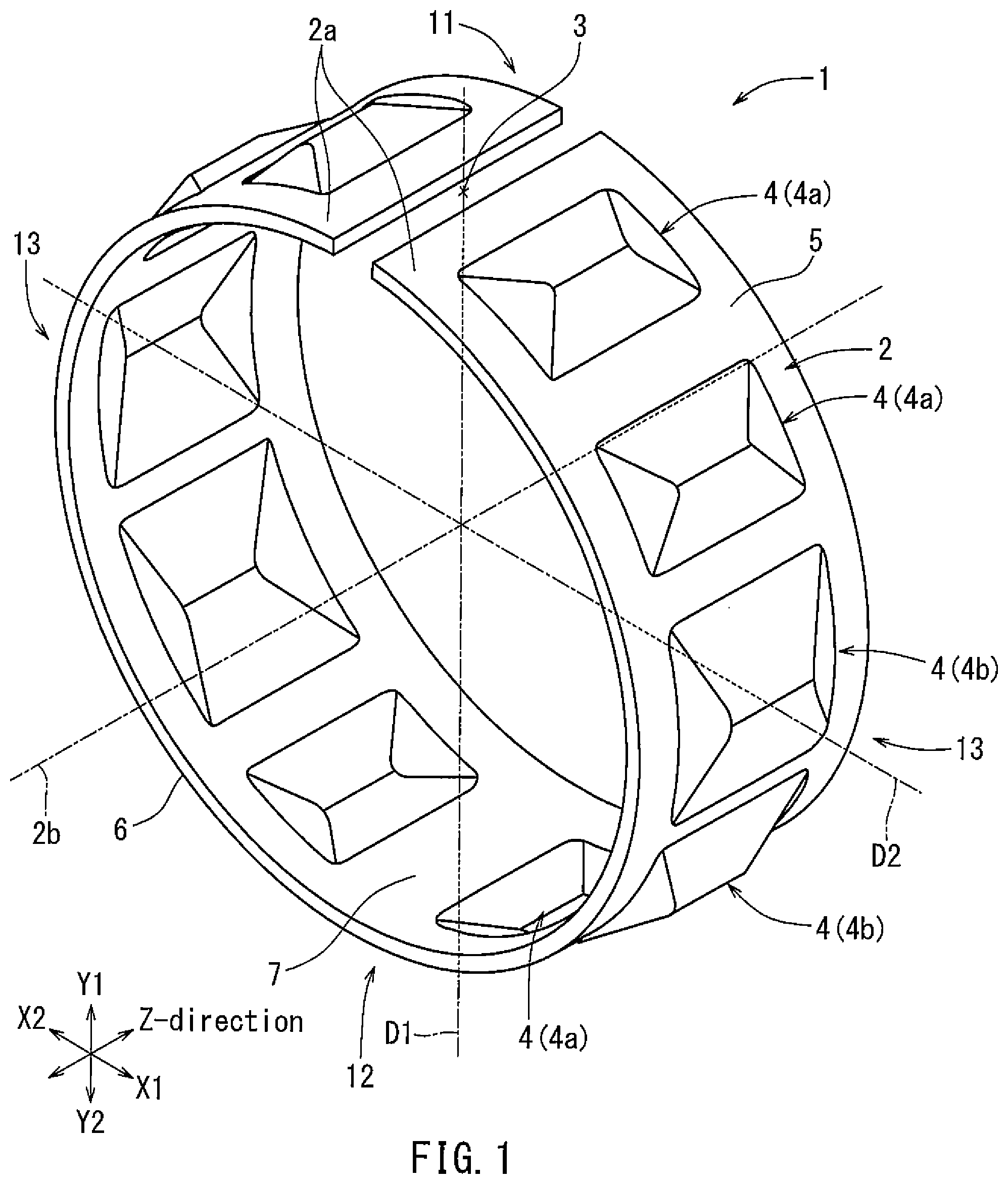
is a perspective view of a tolerance ring according to a first embodiment.
is a front view of the tolerance ring of .
is a plan view of the tolerance ring of , with a half of the circumferential portion expanded.
is a cross-sectional view taken along line IV-IV in .
is a cross-sectional view taken along line V-V in .
is a front view of the tolerance ring according to a second embodiment.
is a plan view of the tolerance ring of , with a half of the circumferential portion expanded.
is a cross-sectional view taken along line VIII-VIII in .
is a front view of the tolerance ring according to a third embodiment.
is a plan view of the tolerance ring of , with a half of the circumferential portion expanded.
is a cross-sectional view taken along line XI-XI in .
is a front view of the tolerance ring according to a fourth embodiment.
is a plan view of the tolerance ring of , with a half of the circumferential portion expanded.
is a cross-sectional view taken along line XIV-XIV in .
is a cross-sectional view taken along line XV-XV in .
is a cross-sectional view taken along line XVI-XVI in .
is a front view of the tolerance ring according to a fifth embodiment.
is a plan view of the tolerance ring of , with a half of the circumferential portion expanded.
is a cross-sectional view taken along line XIX-XIX in .
is a front view of the tolerance ring according to a sixth embodiment.
is a plan view of the tolerance ring of , with a half of the circumferential portion expanded.
is a cross-sectional view taken along line XXII-XXII in .
is a graph showing the circumferential distribution of the radial reaction force of the tolerance ring along an X-direction of the semi-circumferential region of .
is a graph showing the circumferential distribution of the X-direction components of the reaction force of .
is a graph showing the circumferential distribution of the Y-direction components of the reaction force of .
is a table comparing the sum of the X-direction components with the sum of the Y-direction components of the radial reaction force of the tolerance ring of .
is a graph showing the circumferential distribution of the X-direction components of the radial reaction force along the X-direction of the semi-circumferential region of .
is a graph showing the circumferential distribution of the Y-direction components of the radial reaction force along the X-direction of the semi-circumferential region of .
is a table comparing the sum of the X-direction components with the sum of the Y-direction components of the radial reaction force of the tolerance ring of .
DETAILED DESCRIPTION
One embodiment of the present disclosure will be described with reference to to 5 , and to 26 . As shown in , a tolerance ring 1 according to a first embodiment includes a cylindrical ring body 2 and a plurality of protrusions 4 . As shown in , the tolerance ring 1 is used while being fitted between a shaft member S and an outer peripheral member H. The shaft member S is, for example, a rotor shaft having a spline fitting portion.
The shaft member (e.g., a rotor shaft) S is a columnar and, for example, solid metal member. The outer peripheral member H may have, for example, a cylindrical shape. The shaft member S is inserted into the center hole of the outer peripheral member H. The outer peripheral member H has an inner peripheral surface Ha radially facing the rotor shaft. The inner peripheral surface Ha encloses the rotor shaft in a circumferential direction. A cylindrical clearance having a short radial length is formed between the shaft member S and the outer peripheral member H. The tolerance ring 1 is fitted in this cylindrical clearance in a press-fitted manner.
As shown in , the ring body 2 may be formed, for example, in a cylindrical shape by rolling a strip plate material having a spring property. The strip plate material is formed of a metal material, such as iron or alloy steel, such as high carbon steel or stainless steel, non-ferrous metal, such as copper or nickel, metal alloy, or the like.
As shown in , the ring body 2 includes end edges 2 a in the circumferential direction and in a direction corresponding to its longitudinal direction. The both end edges 2 a face opposite to each other, and an abutment joint portion 3 is formed between the end edges 2 a . A plurality of, for example ten, protrusions 4 may be formed on the ring body 2 . The plurality of the protrusions 4 protrude radially outward from the ring body 2 and each have a reaction force due to their radial rigidity. The plurality of protrusions 4 are located in the axial center region of the ring body 2 and are disposed in one row at predetermined intervals in the circumferential direction. The ring body 2 has an outer peripheral cylindrical surface 5 with no protrusions 4 formed. The outer peripheral cylindrical surface 5 includes a region extending along both axial end edges of the ring body 2 and a region axially extending between the protrusions 4 .
As shown in , the outer peripheral cylindrical surface 5 and the inner peripheral portion 6 , which is an inner peripheral side of the ring body 2 , are substantially circular in a cross section orthogonal to an axis center line 2 b of the ring body 2 . The tolerance ring 1 has an opposing portion 7 radially facing the abutment joint portion 3 on a line connecting the abutment joint portion 3 and passing through the axis center line 2 b of the ring body 2 .
As shown in , the inner peripheral portion 6 comes in contact with the outer peripheral portion of the shaft member S while the tolerance ring 1 is fitted to the shaft member S. The tops of the protrusions 4 are pressed by the inner peripheral surface Ha of the outer peripheral member H. The shaft member S and outer peripheral member H are subjected to a reaction force caused by the spring property of the ring body 2 and the radial rigidity of each of the protrusions 4 . The shaft member S is subjected to the reaction force in a direction toward its shaft center. The outer peripheral member H is subjected to the reaction force in a radially outward direction, which is a direction generally opposite to the reaction force received by the shaft member S. The shaft member S and/or the outer peripheral member H may deform due to the reaction force. Since the shaft member S is solid, the deformation due to being compressed is small. In contrast, since the outer peripheral member H is hollow, the deformation tends to be greater than that of the shaft member S. Therefore, a risk of deformation due to the reaction force of the tolerance ring 1 is mainly extended to the outer peripheral member H.
As shown in , the tolerance ring 1 can be described with reference to X-, Y-, and Z-directions, which are orthogonal to each other. The Z-direction is a direction along the axis center line 2 b of the ring body 2 . The Y-direction extends along a straight line D 1 connecting the axis center line 2 b of the ring body 2 and the abutment joint portion 3 . The X-direction is orthogonal to both the Y-direction and Z-direction, and extends along a straight line D 2 , which passes through the axis center line 2 b . In other words, the straight line D 1 extends in the Y-direction, while the straight line D 2 extends in the X-direction.
As shown in , a direction parallel to a direction directing from the axis center line 2 b of the ring body 2 toward the abutment joint portion 3 (upward direction in ) is defined as a Y1 direction. The Y1 direction is oriented upward from the straight line D 2 . A direction parallel to a direction directing from the axis center of the ring body 2 toward the opposing portion 7 (downward direction in ) is defined as a Y2 direction. The Y2 direction is oriented downward from the straight line D 2 . A direction parallel to a direction directing from the axis center of the ring body 2 toward the right direction is defined as an X1 direction. The X1 direction is oriented from the straight line D 1 to the right. A direction parallel to a direction directing from the axis center of the ring body 2 to the left direction is defined as an X2 direction. The X2 direction is oriented from the straight line D 1 to the left.
As shown in , the tolerance ring 1 includes an abutment joint semi-circumferential region 11 and an opposing semi-circumferential region 12 separated by the straight line D 2 . The abutment joint semi-circumferential region 11 includes the abutment joint portion 3 , and may, for example, include the abutment joint portion 3 at the center of a circular arc. The opposing semi-circumferential region 12 includes the opposing portion 7 , and may, for example, include the opposing portion 7 at the center of a circular arc. The tolerance ring 1 includes a first X-direction semi-circumferential region 13 and a second X-direction semi-circumferential region 13 separated by the straight line D 1 . The first and second X-direction semi-circumferential regions 13 include a portion of the abutment joint portion 3 at one end and a portion of the opposing portion 7 at the other end.
As shown in , the first and second X-direction semi-circumferential regions 13 are symmetrical to each other with respect to the straight line D 1 . The plurality of the protrusions 4 are located in positions to be symmetrical to each other with respect to the straight line D 1 . As shown in , the protrusions 4 are rectangular in a planner view. As shown in , the protrusions 4 protrude radially outward from the ring body 2 and have a triangular ridge shape in a cross-section as seen from the Z-direction. As shown in , the protrusions 4 have a trapezoidal ridge shape in a cross-section obtained by cutting the ring body 2 in the axial direction.
As shown in to 4 , a small protrusion 4 a , an interval 5 a , a small protrusion 4 a , an interval 5 b , a large protrusion 4 b , an interval 5 c , a large protrusion 4 b , an interval 5 d , a small protrusion 4 a , and an interval 5 e are formed in this order on the outer peripheral cylindrical surface 5 of the first X-direction semi-circumferential region 13 , from the end edge 2 a and along the circumferential direction. The interval 5 b has a shorter circumferential length than that of the interval 5 a . The interval 5 c has an even shorter circumferential length than that of the interval 5 b . The interval 5 d has substantially the same circumferential length as that of the interval 5 b . The interval 5 e has a longer circumferential length than that of the interval 5 a . The distance between the pair of small protrusions 4 a with the opposing portion 7 placed therebetween is equivalent to twice the interval 5 e.
As shown in , the small protrusions 4 a have substantially the same radial height as the large protrusions 4 b . Therefore, the tops of the small protrusions 4 a and the tops of the large protrusions 4 b may evenly come in contact with the inner peripheral surface Ha, having substantially a circular cross-section, of the outer peripheral member H. As shown in , the large protrusions 4 b have substantially the same axial length as the small protrusions 4 a . On the other hand, the large protrusions 4 b are longer in circumferential length than the small protrusions 4 a . For example, the large protrusions 4 b may be, for example 10 to 50%, longer in the circumferential length than the small protrusions 4 a . The rigidity of the region including the large protrusions 4 b may thus be, for example 20% to 40%, lower than the rigidity in the region including the small protrusions 4 a.
As shown in , the pair of first small protrusions 4 a , the pair with the abutment joint portion 3 interposed therebetween in the circumferential direction, is formed near the edge of the respective end edges 2 a in the abutment joint semi-circumferential region 11 . The pair of second small protrusions 4 a , a pair mirrored across the straight line D 1 , is formed with the pair of first small protrusions 4 a and the pair of intervals 5 a interposed therebetween. The pair of first large protrusions 4 b , including their tops, is formed and located next to respective second small protrusions 4 a via respective intervals 5 b.
As shown in , the interval 5 e is formed at the opposing portion 7 located in the opposing semi-circumferential region 12 . A pair of the third small protrusions 4 a , a pair mirrored across straight line D 1 , is formed with the interval 5 e interposed therebetween in the circumferential direction. A pair of the second large protrusions 4 b , a pair mirrored across straight line D 1 , is formed with the interval 5 e , the third small protrusions 4 a , and the intervals 5 d interposed therebetween. The pair of first large protrusions 4 b , excluding their tops, is formed and located next to respective second large protrusions 4 b via respective intervals 5 c.
As shown in , the reaction force, which is due to the rigidity of the protrusions 4 , of the tolerance ring 1 acts radially from the tops of the protrusions 4 against the portion of the outer peripheral member H enclosing the outer circumference of the tolerance ring 1 . The reaction force vector F acting from the top of each protrusion 4 is divided into force vector components, such as a Y1-direction component FY 1 , a Y2-direction component FY 2 , an X1-direction component FX 1 , and an X2-direction component FX 2 . The X-direction component and the Y-direction component of this reaction force vector F will be described based on the analysis results shown in to 26 . A right side of each graph in to 25 (the side at 170° of the horizontal axis) is the side of the abutment joint portion 3 of the ring member 2 , while a left side of each graph (the side at 0° of the horizontal axis) is the side of the opposing portion 7 of the ring member 2 .
As shown in , the first and second X-direction semi-circumferential regions 13 are symmetrical to each other with respect to the straight line D 1 . Therefore, circumferential distributions of the X2-direction component FX 2 and the X1-direction component FX 1 of the reaction force vector F are symmetrical. Thus, since the X2-direction component FX 2 of the reaction force vector F is effectively the same as the X1-direction component FX 1 in the analysis result, merely the X1-direction component FX 1 will be described, and the description for the X2-direction component FX 2 will be omitted. shows the circumferential distribution of the X1-direction component FX 1 of the first X-direction semi-circumferential region 13 . In , 0° to 90° along the horizontal axis indicates the circumferential distribution of the Y2-direction component FY 2 of the first X-direction semi-circumferential region 13 . 90° to 170° along the horizontal axis indicates the circumferential distribution of the Y1-direction component FY 1 of the first X-direction semi-circumferential region 13 . Therefore, the sum of the Y2-direction components ΣFY 2 of the opposing semi-circumferential region 12 is indicated by doubling the reaction force of 0° to 90° indicated in . The sum of the Y1-direction components ΣFY 1 of the abutment joint semi-circumferential region 11 is indicated by doubling the reaction force of 90° to 170° indicated in .
A comparative tolerance ring in includes a plurality of protrusions having identical shapes. In other words, in the comparative tolerance ring in , the positions of the tops of the protrusions are identical to the positions of the tops of the protrusions 4 of the tolerance ring 1 of this embodiment, however all the large protrusions 4 b of the tolerance ring 1 described in this embodiment are replaced with the small protrusions for the comparative tolerance ring.
As shown in , the reaction force vector F of both the tolerance ring 1 of this embodiment and the comparative tolerance ring due to the radial rigidity in the near-edge region of the abutment joint portion 3 (right side in ) is smaller than that of the small protrusions in the other regions. Additionally, the reaction force vector F due to the radial rigidity in the region (the region between about 40° and 100° in ) of the tolerance ring 1 where the large protrusions 4 b are formed is weaker than that in the corresponding region of the comparative tolerance ring. This is because the rigidity of the large protrusions 4 b is lower than the rigidity of the small protrusions 4 a . As shown in , the X1-direction component FX 1 of the reaction force vector F in the region of the tolerance ring 1 where the large protrusions 4 b are formed is less than that of the corresponding region of the comparative tolerance ring.
As shown in , the sum ΣFY 2 of the Y2-direction component FY 2 of the reaction force vector F in the opposing semi-circumferential region 12 is slightly greater than the sum ΣFY 1 of the Y1-direction component FY 1 of the reaction force vector F in the abutment joint semi-circumferential region 11 , by about 0.5% of the sum of the Y2-direction component ΣFY 2 . The sum of the X1-direction component ΣFY 1 (which is equal to the sum of the X2-direction component ΣFY 2 ) reaction force vector F in the first X-direction semi-circumferential region 13 is 99.7% of the sum of the Y1-direction component ΣFY 1 , and is 99.2% of the sum of the Y2-direction component ΣFY 2 . In other words, the sum of the X1-direction component ΣFX 1 is set to be slightly less than both the sum of the Y1-direction component ΣFY 1 and the sum of the Y2-direction component ΣFY 2 .
Referring to and , the sum ΣFY 1 of the X-direction component FX 1 of the reaction force vector F in the first X-direction semi-circumferential region 13 is only slightly less than the sum ΣFY 1 of the Y1-direction component FY 1 of the reaction force vector F in the abutment joint semi-circumferential region 11 . Therefore, the X-direction component force exerted from the first X-direction semi-circumferential region 13 to the inner peripheral surface Ha of the outer peripheral member H is approximately the same as the force of the Y-direction component exerted from the abutment joint semi-circumferential region 11 to the inner peripheral surface Ha of the outer peripheral member H.
More specifically, the force exerted to the inner peripheral surface Ha of the outer peripheral member H tends to be relatively smaller in the near-edge region of the abutment joint portion 3 of the abutment joint semi-circumferential region 11 than in other regions. However, the sum ΣFY 1 of the reaction force vector FX 1 of the X1-direction component of the plurality of the protrusions 4 located in the first X-direction semi-circumferential region 13 is set to be equal to or less than the sum ΣFY 1 of the reaction force vector FY 1 of the Y1-direction component of the plurality of protrusions 4 located in the abutment joint semi-circumferential region 11 . As a result, it was found that the force actually exerted to the inner peripheral surface Ha of the outer peripheral member H becomes substantially constant. In other words, the outer peripheral member H deforms in a shape close to a perfect circle in a cross section. It is thus possible to prevent a deformation that causes the outer peripheral member H to become, for example, elliptical.
Referring to and , the difference between the sum ΣFY 1 of the Y1-direction component FY 1 of the reaction force vector in the abutment joint semi-circumferential region 11 and the sum ΣFY 2 of the Y2-direction component FY 2 of the reaction force vector in the opposing semi-circumferential region 12 may be equal to or less than 10% of the sum of the Y2-direction component ΣFY 2 , for example within about 0.5%. The force in the Y-direction exerted from the abutment joint semi-circumferential region 11 to the inner peripheral surface Ha of the outer peripheral member H is approximately the same as the force of the Y-direction component exerted from the opposing semi-circumferential region 12 to the inner peripheral surface Ha of the outer peripheral member H. Therefore, the outer peripheral member H deforms in a shape close to a perfect circle in a cross-section.
Referring to and , the plurality of protrusions 4 , include the small protrusions 4 a and the large protrusions 4 b , having various widths in the circumferential direction. The radial reaction force due to the rigidity of the protrusions 4 can be enhanced by narrowing the circumferential width, as is done for the small protrusions 4 a . In this way with a relatively simple structure, the reaction force of the protrusions 4 , more specifically, the reaction force component FX 1 in the X1 direction, the reaction force component FY 1 in the Y1-direction, and the reaction force component FY 2 in the Y2-direction, can be set to be predetermined magnitudes.
Referring to , the abutment joint semi-circumferential region 11 and the opposing semi-circumferential region 13 include the small protrusions 4 a , each of which has substantially the same rigidity. Therefore, the sum ΣFY 1 of the X1-direction component of the reaction force vector F, the sum ΣFY 1 of the Y1-direction component of the reaction force vector F, and the sum ΣFY 2 of the Y2-direction component may be easily set by appropriately arranging the protrusions. This facilitates design of a tolerance ring 1 that can reduce unfavorable deformation of the outer peripheral member H.
Another embodiment will be described with reference to to 8 and to 29 . A tolerance ring 20 shown in to 8 , includes a plurality of, for example eight, protrusions 24 on an outer peripheral cylindrical surface 25 , alternative to the plurality of the protrusions 4 and the outer peripheral cylindrical surface 5 of the tolerance ring 1 shown in . As shown in , the tolerance ring 20 includes an abutment joint semi-circumferential region 31 and an opposing semi-circumferential region 32 separated by a straight line D 2 . The abutment joint semi-circumferential region 31 includes an abutment joint portion 3 , and may, for example, include the abutment joint portion 3 in the center of a circular arc. The opposing semi-circumferential region 32 includes the opposing portion 7 , and may, for example, include an opposing portion 7 in the center of the circular arc. The tolerance ring 20 includes a first X-direction semi-circumferential region 33 and a second X-direction semi-circumferential region 33 separated by a straight line D 1 . Each of the first and second X-direction semi-circumferential regions 33 include the abutment joint portion 3 at one end and the opposing portion 7 at the other end.
As shown in to 8 , a small protrusion 24 a , an interval 25 a , a small protrusion 24 a , an interval 25 b , a large protrusion 24 b , an interval 25 c , a small protrusion 24 a , and an interval 25 d are formed in this order on the outer peripheral cylindrical surface 25 of the first X-direction semi-circumferential region 33 , starting from the end edge 2 a and along the circumferential direction. The interval 25 b has a longer circumferential length than the interval 25 a . The interval 25 c has a circumferential length substantially the same as the interval 25 a . The interval 25 d has a shorter circumferential length than the interval 25 a . The distance between the pair of small protrusions 24 a on opposite sided of the opposing portion 7 placed therebetween is equivalent to twice the interval 25 d.
As shown in , the pair of first protrusions 24 a , a pair with the abutment joint portion 3 interposed therebetween in the circumferential direction, is formed near the edge of corresponding end edges 2 a of the abutment joint semi-circumferential region 31 . The pair of second small protrusions 24 a is formed next to corresponding first small protrusions 24 a , each with an interval 25 a formed therebetween. A pair of intervals 25 b is formed across the straight line D 2 on respective circumferential sides of the pair of second small protrusions 24 a.
As shown in , the interval 25 d is formed at the opposing portion 7 in the opposing semi-circumferential region 32 . The pair of third small protrusions 24 a is formed with the interval 25 d interposed in the circumferential direction. The pair of large protrusions 24 b is formed with the interval 25 d , the third small protrusions 24 a , and the intervals 25 c interposed therebetween. The pair of intervals 25 b is formed across the straight line D 2 on corresponding circumferential sides of the pair of large protrusions 24 b.
The X-direction component and the Y-direction component of a reaction force vector F due to the rigidity of the protrusions 24 of the tolerance ring 20 will be described based on the analysis results shown in to 29 . A right side of each graph in (the side at 170° of the horizontal axis) is the side of the abutment joint portion 3 of the tolerance ring 20 , while a left side of each graph (the side at 0° of the horizontal axis) is the side of the opposing portion 7 of the tolerance ring 20 . That applied in may also be generally applied in . A comparative tolerance ring in includes a plurality of protrusions, each of which has an identical shape. In other words, in the comparative tolerance ring in , the positions of the tops of the protrusions are identical to the positions of the tops of the protrusions 24 of the tolerance ring 20 of this embodiment, however the large protrusions 24 b of the tolerance ring 20 of this embodiment are replaced with the small protrusions in the comparative example.
As shown in , the X1-direction component FX 1 of the reaction force vector F in the region of the tolerance ring 20 where the large protrusions 24 b are formed, is smaller than that in the corresponding region of the comparative tolerance ring.
As shown in , the sum ΣFY 2 of the Y2-direction component FY 2 of the reaction force vector F in the opposing semi-circumferential region 32 is greater than the sum ΣFY 1 in the Y1-direction component FY 1 of the reaction force vector F in the abutment joint semi-circumferential region 31 , by about 2.1% of the sum of the Y2-direction components ΣFY 2 . The sum ΣFY 1 of the X1-direction component FX 1 of the reaction force vector F in the first X-direction semi-circumferential region 33 (which also equals the sum of the X2-direction components ΣFY 2 ) is 99.5% of the sum of the Y1-direction components ΣFY 1 , and is 97.4% of the sum of the Y2-direction components ΣFY 2 . In other words, the sum of the X1-direction components ΣFY 1 is set to be slightly less than both the sum of the Y1-direction components ΣFY 1 and the sum of the Y2-direction components ΣFY 2 , i.e., substantially identical.
Referring to , 6 , 26 , and 29 , the tolerance ring 20 of this embodiment exhibits substantially the same effect as the tolerance ring 1 shown in . Therefore, the outer peripheral member H deforms in a shape close to a perfect circle in cross section. It is thus possible to prevent such deformation that causes the outer peripheral member H to become, for example, elliptical.
Another embodiment will be described with reference to to 11 and to 32 . A tolerance ring 40 , shown in to 11 , includes a plurality of, for example six, protrusions 44 on an outer peripheral cylindrical surface 45 , alternative to the plurality of the protrusions 4 on the outer peripheral cylindrical surface 5 of the tolerance ring 1 shown in . As shown in , the tolerance ring 40 includes an abutment joint semi-circumferential region 51 and an opposing semi-circumferential region 52 separated by a straight line D 2 . The abutment joint semi-circumferential region 51 includes an abutment joint portion 3 , and may, for example, include the abutment joint portion 3 in the center of a circular arc. The opposing semi-circumferential region 52 includes an opposing portion 7 , and may, for example, include the opposing portion 7 in the center of the circular arc. The tolerance ring 40 includes a first X-direction semi-circumferential region 53 and a second X-direction semi-circumferential region 53 separated by a straight line D 1 . The first and second X-direction semi-circumferential regions 53 each include the abutment joint portion 3 at one end and the opposing portion 7 at the other end.
As shown in to 11 , a small protrusion 44 a , an interval 45 a , a large protrusion 44 b , an interval 45 b , a small protrusion 44 a , and an interval 45 c are formed in this order on the outer peripheral cylindrical surface 45 in the first X-direction semi-circumferential region 53 , the order being from the end edge 2 a and along in the circumferential direction. The interval 45 b nearer the straight line D 2 is longer in a circumferential length than that the interval 45 a nearest the end edge 2 a . The interval 45 c nearer the opposing portion 7 is shorter in circumferential length than the interval 45 a nearer the end edge 2 a . The distance between the pair of small protrusions 44 a , the pair with the opposing portion 7 placed therebetween, is equivalent to twice the interval 45 c.
As shown in , the pair of first protrusions 44 a , the pair formed near the edge of the end edges 2 a , is in the abutment joint semi-circumferential region 51 , the region with the abutment joint portion 3 interposed in the circumferential direction. The pair of large protrusions 44 b is positioned next to the first small protrusions 44 a via the interval 45 a . Approximately three quarters or two thirds (for example, 60% to 70%) of the large protrusion 44 b , including the top may, be located in the abutment joint semi-circumferential region 51 . The rest of the approximately one quarter or one third of the large protrusion 44 b may be located in the opposing semi-circumferential region 52 .
As shown in , the interval 45 c is formed at the opposing portion 7 in the opposing semi-circumferential region 52 . The pair of second small protrusions 44 a is formed with this interval 45 c interposed therebetween in the circumferential direction. The pair of large protrusions 44 b is formed with respective second small protrusions 44 a and intervals 45 b interposed therebetween.
The X-direction component and the Y-direction component of a reaction force vector due to the rigidity of the protrusions 44 of the tolerance ring 40 will be described based on the analysis results shown in to 32 . A right side of each graph in (the side at 170° of the horizontal axis) is the side of the abutment joint portion 3 , while a left side of each graph (the side at 0° of the horizontal axis) is the side of the opposing portion 7 . The general principles applied in may also be applied to . A comparative tolerance ring in includes a plurality of protrusions, each protrusion having an identical shape. In other words, in the comparative tolerance ring in , the positions of the tops of the protrusions are identical to the positions of the tops of the protrusions 44 of the tolerance ring 40 of this embodiment. However, the large protrusions 44 b of the tolerance ring 40 of this embodiment are replaced with the small protrusions for the comparative example.
As shown in , the X1-direction component FX 1 of the reaction force vector F in the region of the tolerance ring 40 where the large protrusions 44 b are formed, is smaller than that of the corresponding region of the comparative tolerance ring.
As shown in , the sum ΣFY 2 of the Y2-direction components FY 2 of the reaction force vector F in the opposing semi-circumferential region 52 is slightly smaller than the sum ΣFY 1 of the Y1-direction components FY 1 of the reaction force vector F in the abutment joint semi-circumferential region 51 , by about 0.4% of the sum ΣFY 2 of the Y2-direction components FY 2 . The sum ΣFY 1 of the X1-direction component FX 1 of the reaction force vector F in the first X-direction semi-circumferential region 53 (which also equals the sum of the X2-direction components ΣFY 2 ) is 99.5% of the sum of the Y1-direction components ΣFY 1 , and 99.9% of the sum of the Y2-direction components ΣFY 2 . In other words, the sum ΣFY 1 of the X1-direction components FX 1 is set to be slightly less than both the sum of the Y1-direction components FY 1 ΣFY 1 and the sum of the Y2-direction components ΣFY 2 , i.e., they are substantially identical.
Referring to , 9 , 26 and 32 , the tolerance ring 40 exhibits substantially the same effect as the tolerance ring 1 shown in . Therefore, the outer peripheral member H deforms in a shape close to a perfect circle in cross section. It is thus possible to prevent deformation that causes the outer peripheral member H to become, for example, elliptical.
Another embodiment will be described with reference to to 16 and to 35 . A tolerance ring 60 shown in to 16 includes a plurality of, for example six, protrusions 64 and on an outer peripheral cylindrical surface 65 , alternative to the plurality of the protrusions 4 and on the outer peripheral cylindrical surface 5 of the tolerance ring 1 shown in . As shown in , the tolerance ring 60 includes an abutment joint semi-circumferential region 71 and an opposing semi-circumferential region 72 , separated from each other by a straight line D 2 . The abutment joint semi-circumferential region 71 includes an abutment joint portion 3 , and may, for example, include the abutment joint portion 3 in the center of a circular arc. The opposing semi-circumferential region 72 includes an opposing portion 7 , and may, for example, include the opposing portion 7 in the center of the circular arc. The tolerance ring 60 includes a first X-direction semi-circumferential region 73 and a second X-direction semi-circumferential region 73 , separated from each other by a straight line D 1 . The first and second X-direction semi-circumferential regions 73 each include the abutment joint portion 3 at one end and the opposing portion 7 at the other end.
As shown in to 16 , a small protrusion 64 a , an interval 65 a , a large protrusion 64 b , an interval 65 b , a small protrusion 64 a , and an interval 65 c are formed in this order on the outer peripheral cylindrical surface 65 in the first X-direction semi-circumferential region 73 , the order being from the end edge 2 a and along in the circumferential direction. The interval 65 b nearer the straight line D 2 is longer in circumferential length than the interval 65 a nearer the end edge 2 a . The interval 65 c nearer the opposing portion 7 is longer in circumferential length than the interval 65 a nearer the end edge 2 a and shorter in circumferential length than the interval 65 b nearer the straight line D 2 . The distance between the pair of small protrusions 64 a , the pair with the opposing portion 7 placed therebetween is equivalent to twice the interval 65 c nearer the opposing portion 7 .
As shown in to 16 , the large protrusions 64 b are longer in axial length than the small protrusions 64 a and also longer in circumferential length than the small protrusions 64 a . Therefore, the rigidity of the large protrusions 64 b is lower than the rigidity of the small protrusions 64 a.
As shown in , a pair of first protrusions 64 a is formed near the edge of the end edges 2 a in the abutment joint semi-circumferential region 71 , with the abutment joint portion 3 interposed therebetween in the circumferential direction. The pair of large protrusions 64 b is formed next to the respective first small protrusions 64 a via the interval 65 a nearer the end edge 2 a . A substantial part (for example, 90% or more) of the large protrusions 64 b , including the tops of the large protrusions 64 b , is located in the abutment joint semi-circumferential region 71 , while a small part that is the rest of the large protrusions 64 b may be located in the opposing semi-circumferential region 72 .
As shown in , the interval 65 c is formed at the opposing portion 7 in the opposing semi-circumferential region 72 . A pair of second small protrusions 64 a is formed with this interval 65 c interposed therebetween in the circumferential direction. A pair of intervals 65 b is formed from respective circumferential sides of these second small protrusions 64 a up to the border with the abutment joint semi-circumferential region 71 .
The X-direction component and the Y-direction component of a reaction force vector F due to the rigidity of the protrusions 64 of the tolerance ring 60 will be described based on the analysis results shown in to 35 . A right side of each graph depicted in (the side at 170° of the horizontal axis) is the side of the tolerance ring 60 with the abutment joint portion 3 , while a left side of each graph (the side at 0° of the horizontal axis) is the side of the tolerance ring 60 with the opposing portion 7 . The general principles applied in may also be applied to . A comparative tolerance ring in includes a plurality of protrusions, each protrusions having an identical shape. In other words, in the comparative tolerance ring in , the positions of the tops of the protrusions are identical to the positions of the tops of the protrusions 64 of the tolerance ring 60 of this embodiment. However, the large protrusions 64 b of the tolerance ring 60 of this embodiment are replaced with the small protrusions.
As shown in , the X1-direction component FX 1 of the reaction force vector F in the region of the tolerance ring 60 where the large protrusions 64 b are formed, is smaller than that of the corresponding region of the comparative tolerance ring.
As shown in , the sum ΣFY 2 of the Y2-direction component FY 2 of the reaction force vector F in the opposing semi-circumferential region 72 is slightly greater than the sum ΣFY 1 of the Y1-direction component FY 1 of the reaction force vector F in the abutment joint semi-circumferential region 71 , by about 0.3% of the sum ΣFY 2 of the Y2-direction components FY 2 . The sum of the X1-direction components ΣFY 1 (which is also substantially equal to the sum of the X2-direction components ΣFY 2 ) of the reaction force vector F in the first X-direction semi-circumferential region 73 is 98.0% of both the sum of the Y1-direction components ΣFY 1 and 97.7% of the sum of the Y2-direction components ΣFY 2 . In other words, the sum of the X1-direction components ΣFY 1 is set to be slightly less than both the sum of the Y1-direction components ΣFY 1 and the sum of the Y2-direction components ΣFY 2 , i.e., they are substantially identical.
Referring to , 12 , 26 , and 35 , the tolerance ring 60 of this embodiment exhibits substantially the same effect as the tolerance ring 1 shown in . Therefore, the outer peripheral member H deforms in a shape close to a perfect circle in cross section. It is thus possible to prevent deformation that causes the outer peripheral member H to become, for example, elliptical.
Another embodiment will be described with reference to to 19 and to 38 . A tolerance ring 80 shown in to 19 , includes a plurality of, for example nine, protrusions 84 on an outer peripheral cylindrical surface 85 , alternative to the plurality of the protrusions 4 on the outer peripheral cylindrical surface 5 of the tolerance ring 1 shown in . As shown in , the tolerance ring 80 includes an abutment joint semi-circumferential region 91 and an opposing semi-circumferential region 92 , separated from each other by a straight line D 2 . The abutment joint semi-circumferential region 91 includes an abutment joint portion 3 , and may, for example, include the abutment joint portion 3 in the center of a circular arc. The opposing semi-circumferential region 92 includes an opposing portion 7 , and may, for example, include the opposing portion 7 in the center of the circular arc. The tolerance ring 80 includes a first X-direction semi-circumferential region 93 and a second X-direction semi-circumferential region 93 , separated from each other by a straight line D 1 . The first and second X-direction semi-circumferential regions 93 each include the abutment joint portion 3 at one end and the opposing portion 7 at the other end. The present embodiment is an example where the reaction force vector due to the rigidity of the protrusions can be balanced, even when the total number of protrusions is odd.
As shown in to 19 , a small protrusion 84 a , an interval 85 a , a small protrusion 84 a , an interval 85 b , a small protrusion 84 a , an interval 85 c , a large protrusion 84 b , an interval 85 d , and a small protrusion 84 a are formed in this order on the outer peripheral cylindrical surface 85 in the first X-direction semi-circumferential region 93 , the order being from the end edge 2 a and along in the circumferential direction. The interval 85 b nearer the straight line D 2 is longer in circumferential length than that the interval 85 a nearer the end edge 2 a . Another interval 85 c is shorter in circumferential length than the interval 85 a near the end edge 2 a . The interval 85 d nearer the opposing portion 7 is substantially the same in circumferential length as the interval 85 a nearer the end edge 2 a.
As shown in , the pair of first small protrusions 84 a , the pair formed near the edge of the end edge 2 a , is in the abutment joint semi-circumferential region 91 , with the abutment joint portion 3 interposed therebetween in the circumferential direction. The pair of second small protrusions 84 a is formed next to the first small protrusion 84 a via the interval 85 a . A pair of intervals 85 b is formed on respective circumferential sides of the second small protrusion 84 a nearer the end edge 2 a , the intervals 85 b extending to the boundary with the opposing semi-circumferential region 92 .
As shown in , a single fourth small protrusion 84 a , having a top at the opposing portion 7 , is formed in the opposing semi-circumferential region 92 . A pair of large protrusions 84 b is formed at respective circumferential sides of the fourth small protrusion 84 a , with an interval 85 d interposed therebetween. A pair of third small protrusions 84 a is formed with the respective large protrusions 84 b and the respected interval 85 c placed therebetween.
The X-direction component and the Y-direction component of a reaction force vector due to the rigidity of the protrusions 84 of the tolerance ring 80 will be described based on the analysis results shown in to 38 . A right side of each graph in (the side at 170° of the horizontal axis) is the side of the abutment joint portion 3 of the tolerance ring 80 , while a left side of each graph (the side at 0° of the horizontal axis) is the side of the opposing portion 7 of the tolerance ring 80 . The general principles applied in may also be applied to . A comparative tolerance ring in includes a plurality of protrusions, each protrusion having an identical shape. In other words, in the comparative tolerance ring in , the positions of the tops of the protrusions are identical to the positions of the tops of the protrusions 84 of the tolerance ring 80 of this embodiment. However, the large protrusions 84 b of the tolerance ring 80 of this embodiment are replaced with the small protrusions. The reaction force vector F due to the rigidity of the fourth small protrusions 84 a was analyzed as acting on each of the first and second X-directional semi-circumferential regions 93 with a magnitude of one-half.
As shown in , the X1-direction component FX 1 of the reaction force vector F in the region of the tolerance ring 80 where the large protrusions 84 b are formed is smaller than that of the corresponding region of the comparative tolerance ring.
As shown in , the sum ΣFY 2 of the Y2-direction component FY 2 of the reaction force vector F in the opposing semi-circumferential region 92 is slightly less than the sum ΣFY 1 of the Y1-direction component FY 1 of the reaction force vector F in the abutment joint semi-circumferential region 91 , by about 0.1% of the sum of the Y2-direction components ΣFY 2 . The sum ΣFY 1 of the X1-direction components FX 1 of the reaction force vector F in the first X-direction semi-circumferential region 93 (which is substantially equal to the sum ΣFY 2 of the X2-directions components) is 99.0% of the sum of the Y1-direction components ΣFY 1 and 99.1% of the sum of Y2-direction components ΣFY 2 . In other words, the sum of the X1-direction components ΣFY 1 is set to be slightly less than both the sum of the Y1-direction components ΣFY 1 and the sum of the Y2-direction components ΣFY 2 , i.e., they are substantially identical.
Referring to , 17 , 26 , and 38 , the tolerance ring 80 of this embodiment exhibits substantially the same effect as the tolerance ring 1 shown in . Therefore, the outer peripheral member H deforms in a shape close to a perfect circle in cross section. It is thus possible to prevent deformation that causes the outer peripheral member H to become, for example, elliptical.
Referring to and , the number of the protrusions 84 in the abutment joint semi-circumferential region 91 may be, for example, four and the number of the protrusions 84 in the opposing semi-circumferential region 92 may be, for example, five. Therefore, the protrusions 84 formed in region nearer the opposing portion 7 are more closely arranged than in other regions. More specifically, the force exerted to an inner peripheral surface Ha of an outer peripheral member H tends to be relatively smaller particularly in the region nearer the abutment joint portion 3 of the abutment joint semi-circumferential region 91 than in other regions. The force exerted to the inner peripheral surface Ha of the outer peripheral member H in the near-edge region of the opposing portion 7 in the opposing semi-circumferential region 92 tends to be relatively smaller than in other regions, similar to the force in the near-edge region of the abutment joint portion 3 . Therefore, protrusions 84 with greater rigidity are formed in the abutment joint semi-circumferential region 91 , while the protrusions 84 arranged in the near-edge region of the opposing portion 7 are positioned more closely to each other. With this structure, it is possible to prevent the outer peripheral member H from deforming, particularly, into an elliptical shape extending in the X-direction.
Another embodiment will be described with reference to to 22 and to 41 . A tolerance ring 100 shown in to 22 includes a plurality of, for example ten, protrusions 104 on an outer peripheral cylindrical surface 105 , alternative to the plurality of the protrusions 4 on the outer peripheral cylindrical surface 5 of the tolerance ring 1 shown in . As shown in , the tolerance ring 100 includes an abutment joint semi-circumferential region 111 and an opposing semi-circumferential region 112 , separated from each other by a straight line D 2 . The abutment joint semi-circumferential region 111 includes an abutment joint portion 3 , and may, for example, include the abutment joint portion 3 in the center of a circular arc. The opposing semi-circumferential region 112 includes an opposing portion 7 , and may, for example, include the opposing portion 7 in the center of the circular arc. The tolerance ring 100 includes a first X-direction semi-circumferential region 113 and a second X-direction semi-circumferential region 113 , separated from each other by a straight line D 1 . The first and second X-direction semi-circumferential regions 113 each include the abutment joint portion 3 at one end and the opposing portion 7 at the other end. The present embodiment is an example where a reaction force vector F due to the rigidity of the protrusions can be balanced, even if the protrusions are arranged in a continuous fashion.
As shown in to 22 , a small protrusion 104 a , a small protrusion 104 a , a large protrusion 104 b , a large protrusion 104 b , and a small protrusion 104 a are formed in this order on the outer peripheral cylindrical surface 105 in the first X-direction semi-circumferential region 113 , the order being from the end edge 2 a and along in the circumferential direction. In this embodiment, no interval is formed between the protrusions 104 . The small protrusions 104 a of this embodiment are similar in shape to the small protrusions 4 a of the tolerance ring 1 shown in to 5 , except that they are longer in circumferential length than the small protrusions 4 a of to 5 . The large protrusions 104 b of this embodiment are similar in shape to the large protrusions 4 b of the tolerance ring 1 shown in to 5 , except that they are longer in circumferential length than the large protrusions 4 b of to 5 . The rigidity of the small protrusions 104 a of this embodiment is thus lower than the rigidity of the small protrusions 4 a of the first embodiment. The rigidity of the large protrusions 104 b of this embodiment is lower than the rigidity of the large protrusions 4 b of the first embodiment. As shown in , the small protrusions 104 a are substantially the same in radial height as the large protrusions 104 b . Therefore, the tops of the small protrusions 104 a and the tops of the large protrusions 104 b may come evenly in contact with an inner peripheral surface Ha of an outer peripheral member H in a substantially circular cross-sectional fashion.
As shown in , a pair of the first small protrusions 104 a is formed near the edge of the end edge 2 a of the abutment joint semi-circumferential region 111 , with the joint portion 3 interposed therebetween in the circumferential direction. The pair of second small protrusions 104 a , the pair formed adjacent to respective first small protrusions 104 a is formed. The pair of first large protrusions 104 b is formed adjacent to respective second small protrusions 104 a . Approximately half (e.g., 50% to 60%) of each of the first large protrusions 104 b , including their tops, are located in the abutment joint semi-circumferential region 111 , while the rest of the large protrusions 104 b , a portion without their tops, is located in the opposing semi-circumferential region 112 .
As shown in , a pair of the third small protrusions 104 a is formed side by side via the opposing portion 7 of the opposing semi-circumferential region 112 . A pair of the second large protrusions 104 b is formed adjacent to respective third small protrusions 104 a . A pair of the first large protrusions 104 b is formed adjacent to respective second large protrusions 104 b.
The X-direction component and the Y-direction component of the reaction force vector F due to the rigidity of the protrusions 104 of the tolerance ring 100 will be described based on the analysis results shown in to 41 . A right side of each graph in (the side at 170° of the horizontal axis) is the side of the abutment joint portion 3 of the tolerance ring 100 , while a left side of each graph (the side at 0° of the horizontal axis) is the side of the opposing portion 7 of the tolerance ring 100 . The general principles applied in may also be applied to . A comparative tolerance ring in includes a plurality of protrusions, each protrusions having an identical shape. In other words, in the comparative tolerance ring in , the positions of the tops of the protrusions are identical to the positions of the tops of the protrusions 104 of the tolerance ring 100 of this embodiment. However, the large protrusions 104 b of the tolerance ring 100 of this embodiment are replaced with the small protrusions.
As shown in , the X1-direction component FX 1 of the reaction force vector F in the region of the tolerance ring 100 where the large protrusions 104 b are formed is smaller than that of the corresponding region of the comparative tolerance ring.
As shown in , the sum ΣFY 2 of the Y2-direction components FY 2 of the reaction force vector F in the opposing semi-circumferential region 112 is slightly greater than the sum ΣFY 1 of the Y1-direction components FY 1 of the reaction force vector F in the abutment joint semi-circumferential region 111 , by about 5.5% of the sum of the Y2-direction components ΣFY 2 . The sum ΣFY 1 of the X1-direction component FX 1 of the reaction force vector F in the first X-direction semi-circumferential region 113 (which is about the same as the sum of the X2-direction components ΣFY 2 ) is 99.4% of the sum of the Y1-direction components ΣFY 1 and 94.9% of the sum of the Y2-direction components ΣFY 2 . In other words, the sum of the X1 direction components ΣFY 1 is set to be slightly less than both the sum of the Y1-direction components ΣFY 1 and the sum of the Y2-direction components ΣFY 2 , i.e., substantially identical.
Referring to , 20 , 26 and 41 , the tolerance ring 100 exhibits the same effect as the tolerance ring 1 shown in . Therefore, the outer peripheral member H deforms in a shape close to a perfect circle in a cross section. It is thus possible to prevent such a deformation that the outer peripheral member H becomes, for example, elliptical.
Various modifications may be made to the above-described tolerance rings 1 , 20 , 40 , 60 , 80 , 100 . The ratio of the sum ΣFY of the X-direction components FX of the reaction force vector F due to the rigidity of the protrusions in the X-direction semi-circumferential region with respect to the sum ΣFY 1 of the Y1-direction components FY 1 of the reaction force vector F due to the rigidity of the protrusions in the abutment joint semi-circumferential region may preferably be close to 1. Additionally, the ratio of the sum ΣFY of the X-direction components FX of the reaction force vector F due to the rigidity of the protrusions in the X-direction semi-circumferential region with respect to the sum ΣFY 2 of the Y2-direction components FY 2 of the reaction force vector F due to the rigidity of the protrusions in the opposing semi-circumferential region may preferably be close to 1. The ratio of the sum of the X-direction components ΣFY with respect to the sum of the Y1-direction components ΣFY 1 as well as the ratio of sum of the X-direction components ΣFY with respect to the sum of the Y2-direction components ΣFY 2 may appropriately be changed between 0.77 to 1.2. If the ratio is smaller than 0.77, the outer peripheral member H may elliptically deform in the Y-direction by a non-negligible extent. If the ratio is greater than 1.2, the outer peripheral member H may elliptically deform in the X-direction by a non-negligible extent.
In each of the embodiments, the protrusions are described as being arranged in one row in the circumferential direction of the tolerance ring, however, the arrangement of the protrusions should not be limited thereto. For example, it may be structured so that the rows of the protrusions arranged in the circumferential direction may be axially arranged in parallel in two or more rows. The shape of the protrusions may also be changed accordingly. For example, the protrusions 4 a , 4 b of the first embodiment may have their circumferential length or axial length modified. For example, alternative to the protrusions 4 of the first embodiment, a shape, such as a triangular shape or a hexagonal shape when viewed from the radial direction, may be used for the protrusions 4 . The number of protrusions formed on the tolerance ring, types of the protrusions, such as small protrusions or large protrusions, intervals between adjacent protrusions, etc., may be selected without being limited to those as described in each of the above embodiments. As long as the tolerance ring is used in a state being fitted between a shaft member S and an outer peripheral member H, the present disclosure may be applied to various tolerance rings. These tolerance rings are not limited to, for example, those to be fitted to a shaft member S having a spline fit.
Various embodiments described in detail with reference to the accompanying drawings are representative examples of the present invention and thus non-limiting embodiments. The detailed description is intended to teach a person of skill in the art to make, use, and/or practice various aspects of the present teachings, and thus does not limit the scope of the disclosure in any manner. Furthermore, each of the additional features and teachings disclosed above may be applied and/or used separately or with other features and teachings in any combination thereof, to provide an improved tolerance ring and/or methods of making and using the same.
Figures (16)
Citations
This patent cites (12)
- US8363359
- US9019663
- US9109632
- US10443657
- US20120087044
- US20130105267
- US20130315654
- US20180372164
- US2012-52638
- US2015-517065
- US2017-36785
- US2017-53385