Solar Panel Module Fixed to a Float
Abstract
A structure capable of suppressing load applied to a solar panel module due to thermal expansion and contraction of a float. Provided is a structure including a float, a solar panel module having a plate portion, and a supporting member fixed to the float and supporting the plate portion. The plate portion is supported to be movable relative to the supporting member, and a cushioning member is disposed between the supporting member and the plate portion.
Claims (6)
1. A structure, comprising: a float; a solar panel module comprising a plate portion; and a supporting member fixed to the float and supporting the plate portion, the supporting member having an interior surface including a U-shaped engagement groove and an upper wall portion extending from an end of the U-shaped engagement groove, the interior surface engaged with the plate portion, wherein the plate portion is supported to be movable relative to the supporting member within the U-shaped engagement groove, and a cushioning member is disposed between the supporting member and the plate portion, and a first end of the cushioning member is directly fixed to an exterior surface of the supporting member outside the U-shaped engagement groove of the supporting member, and a second end of the cushioning member is fixed to the upper wall portion of the interior surface of the supporting member, and the exterior surface faces the interior surface.
Show 5 dependent claims
2. The structure of claim 1 , wherein the solar panel module comprises a solar panel, and a frame supporting the solar panel, the plate portion is provided on the frame, and the U-shaped engagement groove is configured to open in a direction of an outer edge of the frame.
3. The structure of claim 1 , wherein the solar panel module comprises a solar panel, the plate portion is provided on the solar panel, and the U-shaped engagement groove is configured to open in an inward direction of the solar panel relative to an edge of the solar panel.
4. The structure of claim 1 , wherein a distance between inner surfaces in the U-shaped engagement groove of the supporting member is larger than a thickness of the plate portion.
5. The structure of claim 2 , wherein the supporting member is configured to support the plate portion provided on an upper side of the frame.
6. The structure of claim 1 , wherein the cushioning member is non-woven.
Full Description
Show full text →
TECHNICAL FIELD
The present invention relates to a structure including a float, a supporting member, and a solar panel module.
BACKGROUND ART
Patent Literature 1 discloses a state in which a solar panel module is fixed to a float.
CITATION LIST
Patent Literature
•
• Patent Literature 1: JP-A-2018-16286
SUMMARY OF INVENTION
Technical Problem
Since upper and lower ends of the solar panel module are fixed to the float in Patent Literature 1, a load is applied to the solar panel module due to thermal expansion and contraction of the float.
The present invention has been made in view of such circumstances and provides a structure capable of suppressing the load applied to the solar panel module due to the thermal expansion and contraction of the float.
Solution to Problem
According to the present invention, provided is a structure, comprising: a float; a solar panel module comprising a plate portion; and a supporting member fixed to the float and supporting the plate portion, wherein the plate portion is supported to be movable relative to the supporting member, and a cushioning member is disposed between the supporting member and the plate portion.
Since the plate portion of the solar panel module is supported to be movable with respect to the supporting member in the configuration of the present invention, it is possible to suppress the load applied to the solar panel module due to the thermal expansion and contraction.
In addition, it was found in such a configuration that an unpleasant contact noise may be generated when the solar panel module moves relative to the supporting member. To address this issue, it has been further found that the generation of contact noise can be suppressed by disposing the cushioning member between the supporting member and the plate portion, and the present invention has been completed.
Hereinafter, various embodiments of the present invention will be exemplified. The embodiments described below can be combined with each other.
Preferably, in the structure, the supporting member comprises an engagement groove engaged with the plate portion, and the plate portion is configured to be movable in the engagement groove.
Preferably, in the structure, the solar panel module comprises a solar panel, and a frame supporting the solar panel, the plate portion is provided on the frame, and the engagement groove is configured to open in an outward direction of the frame.
Preferably, in the structure, the solar panel module comprises a solar panel, the plate portion is provided on the solar panel, and the engagement groove is configured to open in an inward direction of the solar panel.
Preferably, in the structure, a distance between inner surfaces in the engagement groove of the supporting member is larger than a thickness of the plate portion.
Preferably, in the structure, the cushioning member is fixed to the supporting member outside the engagement groove and is not fixed to the supporting member inside the engagement groove.
Preferably, in the structure, the supporting member is configured to support the plate portion provided on an upper side of the frame.
BRIEF DESCRIPTION OF DRAWINGS
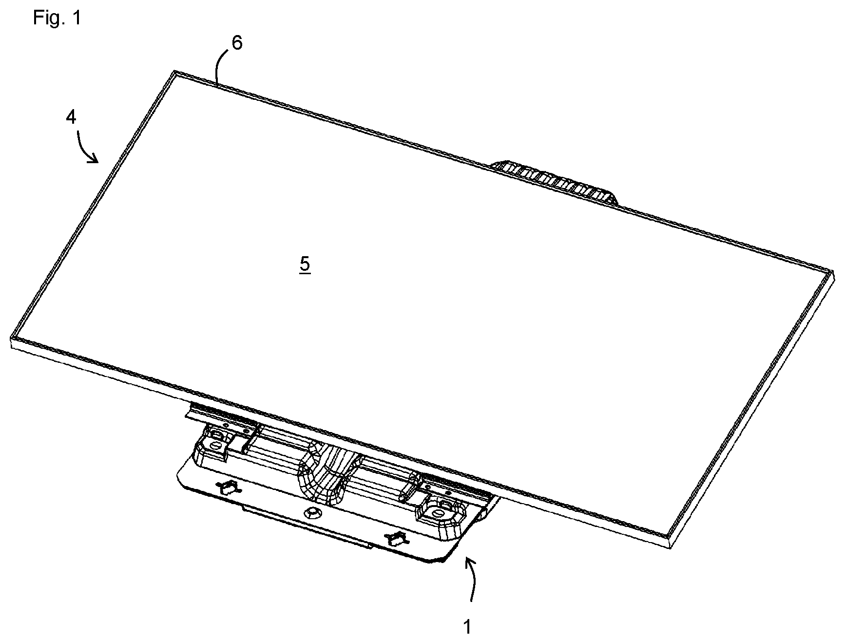
is a perspective view of a structure in which a solar panel module 4 is mounted on a float 1 , according to a first embodiment of the present invention.
is a perspective view when a solar panel 5 is removed from the solar panel module 4 of the structure in .
A is an enlarged view of a region A in .
B is an exploded perspective view of A (a main body 7 is not shown).
A is an enlarged view of the vicinity of the region A in from another angle.
B is an exploded perspective view of A .
A is a cross-sectional view of in a cross section passing through a cushioning member 10 on the right side in B .
B is a cross-sectional view in which an erected wall 8 is excluded from A .
A is a cross-sectional view in which an area C in B is enlarged and a plate portion 6 ua is separated from an engagement groove 2 a.
B is a cross-sectional view corresponding to B , showing a state before the cushioning member 10 is inserted into the engagement groove 2 a.
A is an enlarged view of a region B in .
B is an exploded perspective view of A .
A is an enlarged view of the vicinity of the region B in from another angle.
B is an exploded perspective view of A .
A is a cross-sectional view of in a cross section passing through a nut 3 e.
B is a cross-sectional view in which the main body 7 is excluded from A .
is an exploded view of B .
is a cross-sectional view of a state in which the solar panel 5 is supported by supporting members 2 , 3 , according to a second embodiment of the present invention.
DESCRIPTION OF EMBODIMENTS
Hereinafter, embodiments of the present invention will be described. Various characteristics described in the embodiments below can be combined with each other. Further, the invention is independently established for each characteristic.
1. First Embodiment
A first embodiment of the present invention will be described with reference to to . As shown in to , a structure of the present embodiment includes a float 1 , an upper supporting member 2 , a lower supporting member 3 , and a solar panel module 4 . In the present embodiment, the upper supporting member 2 corresponds to the “supporting member” in Claims.
<Float 1 >
The float 1 supports the solar panel module 4 having a substantially rectangular shape so that shorter sides of the solar panel module 4 can be inclined, as shown in , and is used for installing the solar panel module 4 on water, such as a pond or a lake.
The float 1 is manufactured by blow molding in which a molten cylindrical parison is sandwiched and inflated between a plurality of split molds, and has a structure having a hollow portion for accommodating gas (air or the like) inside. Various kinds of thermoplastic resin can be used as material for molding the float 1 , and for example, polyolefin resin, such as polyethylene and polypropylene, can be preferably used.
As shown in , the float 1 includes a main body 7 and an erected wall 8 . The erected wall 8 is provided to rise from the main body 7 . The float 1 can be manufactured by forming a molded body including the main body 7 and the erected wall 8 , cutting sides other than a side 8 a serving as a hinge when erecting the erected wall 8 , and then rotating and erecting the erected wall 8 around the side 8 a . In this process, an opening 7 c is formed in the part of the main body 7 where the erected wall 8 was originally formed.
<Solar Panel Module 4 >
As shown in , the solar panel module 4 includes a solar panel 5 and a frame 6 supporting the solar panel 5 . The frame 6 has a rectangular shape surrounding the solar panel 5 and includes an upper side 6 u , a lower side 6 b , a right side 6 r , and a left side 61 . As shown in B , each side is provided with a plate portion 6 a extending from a base portion 6 d in an inward direction of the frame 6 . The base portion 6 d is provided with an engagement concave portion 6 e to which the solar panel 5 can be attached.
<Upper Supporting Member 2 , Cushioning Member 10 >
As shown in A to B , the upper supporting member 2 is fixed to an upper end of the erected wall 8 . A plate portion 6 ua of the upper side 6 u is supported by the upper supporting member 2 . The upper supporting member 2 has an engagement groove 2 a opening in an outward direction of the frame 6 . The plate portion 6 ua is engaged with the engagement groove 2 a , so that the plate portion 6 ua is supported by the upper supporting member 2 .
The upper supporting member 2 includes an upper wall portion 2 b , a side wall portion 2 c , and a U-shaped portion 2 d . The upper wall portion 2 b and the side wall portion 2 c are flat and abut respectively on an upper surface 8 b and a side surface 8 c of the erected wall 8 . The U-shaped portion 2 d has a U-shape and is provided to be continuous with the upper wall portion 2 b . The U-shaped portion 2 d is provided with the engagement groove 2 a.
The upper supporting member 2 is an elongated member, and a pair of upper supporting members 2 are fixed to the erected wall 8 . The upper supporting members 2 are fixed to the erected wall 8 to protrude from the erected wall 8 . One upper supporting member 2 protrudes to the right side of the erected wall 8 , and the other upper supporting member 2 protrudes to the left side of the erected wall 8 .
The upper supporting member 2 has a mounting hole 2 c 1 on the side wall portion 2 c and can be fixed to the erected wall 8 by inserting a bolt (not shown) into the mounting hole 2 c 1 and screwing this bolt into a rasp-cut nut embedded in the erected wall 8 .
The plate portion 6 ua is not fixed to the engagement groove 2 a and is movable relative to the engagement groove 2 a . Further, as shown in A , the distance T1A between the inner surfaces in the engagement groove 2 a of the upper supporting member 2 is larger than the thickness T2 of the plate portion 6 ua . Further, the distance T1B between the inner surfaces of the cushioning member 10 in the engagement groove 2 a is equal to or larger than the thickness T2 of the plate portion 6 ua . Consequently, the plate portion 6 ua can easily move relative to the engagement groove 2 a . The value of T1A/T2 is, for example, 1.2 to 3.0, and specifically, for example, 1.2, 1.4, 1.6, 1.8, 2.0, 2.2, 2.4, 2.6, 2.8, 3.0, and may be within the range between any two of the numerical values exemplified herein. The value of T1B/T2 is, for example, 0.8 to 2.8, and specifically, for example, 0.8, 0.9, 1.0, 1.1, 1.2, 1.4, 1.6, 1.8, 2.0, 2.2, 2.4, 2.6, 2.8, and may be within the range between any two of the numerical values exemplified herein. When the cushioning member 10 is a member that can be easily compressed, such as a non-woven fabric, the plate portion 6 ua can move relative to the engagement groove 2 a even if T1B/T2 is 0.8 to 1.
With such a configuration, the plate portion 6 ua is supported to be movable with respect to the upper supporting member 2 . Consequently, the plate portion 6 ua can move relative to the upper supporting member 2 as the frame 6 expands or contracts, thereby suppressing the load applied to the solar panel module 4 .
The frame 6 and the upper supporting member 2 are preferably made of metal, such as aluminum. Consequently, when the plate portion 6 ua moves relative to the upper supporting member 2 , they may be rubbed with each other and cause unpleasant contact noise. The cushioning member 10 is provided between the upper supporting member 2 and the plate portion 6 ua to suppress the generation of such contact noise. The cushioning member 10 can be made of material that can suppress the generation of contact noise, such as a non-woven fabric.
In this regard, as shown in B , an upper surface of the plate portion 6 ua abuts on the cushioning member 10 inside the engagement groove 2 a , and a lower surface of the base portion 6 d abuts on the cushioning member 10 on the upper wall portion 2 b outside the engagement groove 2 a.
It is not easy to attach the cushioning member 10 to the inside of the engagement groove 2 a . For this reason, the cushioning member 10 is fixed to the upper supporting member 2 outside the engagement groove 2 a and is not fixed to the upper supporting member 2 inside the engagement groove 2 a . More specifically, both ends 10 a , 10 b of the cushioning member 10 are fixed to the upper supporting member 2 at positions across the engagement groove 2 a , and the other parts are not fixed to the upper supporting member 2 . In the present embodiment, both ends 10 a , 10 b are fixed to an upper surface of the upper wall portion 2 b and an upper surface of the U-shaped portion 2 d , respectively.
The cushioning member 10 can be disposed inside the engagement groove 2 a by pushing the cushioning member 10 into the engagement groove 2 a by the plate portion 6 ua while both ends 10 a , 10 b of the cushioning member 10 are fixed to the upper supporting member 2 , as shown in B .
The cushioning member 10 has an elongated shape. A plurality of cushioning members 10 are provided at intervals in the longitudinal direction of the upper supporting member 2 . In the present embodiment, two cushioning members 10 are provided at both ends of the upper supporting member 2 in the longitudinal direction. As shown in B , the value of (length L1 of the cushioning members 10 )/(length L2 of the upper supporting member 2 ) in the longitudinal direction of the upper supporting member 2 is, for example, 0.05 to 0.4, and preferably 0.1 to 0.3, and specifically, for example, 0.05, 0.1, 0.2, 0.3, 0.4, and may be within the range between any two of the numerical values exemplified herein. By providing a plurality of cushioning members 10 of such an elongated shape, direct contact between the plate portion 6 ua and the upper supporting member 2 is avoided while reducing the friction between the cushioning member 10 and the plate portion 6 ua.
<Lower Supporting Member 3 >
As shown in A to , the lower supporting member 3 is fixed to the main body 7 . A plate portion 6 ba of the lower side 6 b is supported by the lower supporting member 3 . The lower supporting member 3 includes an engagement groove 3 a opening in an outward direction of the frame 6 . The plate portion 6 ba is engaged with the engagement groove 3 a , so that the plate portion 6 ba is supported by the lower supporting member 3 .
The lower supporting member 3 includes an upper portion 3 b , a lower portion 3 c , and a U-shaped portion 3 d . The upper portion 3 b and the lower portion 3 c are flat and abut respectively on an upper step 7 a and a lower step 7 b having a stepped structure provided on the main body 7 . The U-shaped portion 3 d is U-shaped and is provided to be continuous with the upper portion 3 b . The U-shaped portion 3 d is provided with the engagement groove 3 a.
As shown in A to , the upper portion 3 b is provided with a pedestal portion 3 b 1 , and the pedestal portion 3 b 1 is provided with a locking projection 3 b 2 . The pedestal portion 3 b 1 is a portion formed one step higher, and the locking projection 3 b 2 is a projection protruding from the pedestal portion 3 b 1 in the out-of-plane direction. The lower side 6 b is placed on the pedestal portion 3 b 1 and is locked by the locking projection 3 b 2 .
The lower supporting member 3 is an elongated member, and a pair of lower supporting members 3 are fixed to the main body 7 . The lower supporting members 3 are fixed to the main body 7 to protrude from the main body 7 . One lower supporting member 3 protrudes to the right side of the main body 7 , and the other lower supporting member 3 protrudes to the left side of the main body 7 .
As shown in B , the lower supporting member 3 has a mounting hole 3 c 1 on the lower portion 3 c and can be fixed to the main body 7 by inserting a bolt (not shown) into the mounting hole 3 c 1 and screwing this bolt into a rasp-cut nut embedded in the lower step 7 b.
As shown in A to B , the plate portion 6 ba is fixed with respect to the engagement groove 3 a . A through hole 3 d 1 penetrating the U-shaped portion 3 d is provided at a position where the lower supporting member 3 protrudes from the main body 7 . Further, the plate portion 6 ba is provided with a through hole 6 ba 1 at a position facing the through hole 3 d 1 . As shown in B , the plate portion 6 ba can be fixed to the engagement groove 3 a by inserting a bolt (not shown) into the through holes 3 d 1 , 6 ba 1 from a side of a lower surface 3 d 3 of the U-shaped portion 3 d and screwing it into a nut 3 e disposed on an upper surface 3 d 2 of the U-shaped portion 3 d while the lower side 6 b is placed on the pedestal portion 3 b 1 and abuts on the locking projection 3 b 2 .
2. Second Embodiment
The structure of the second embodiment of the present invention is similar to the first embodiment, and the main difference is in the configuration of the solar panel module 4 and the engagement grooves 2 a , 3 a . Hereinafter, the difference will be mainly described.
In the present embodiment, the solar panel module 4 does not include the frame 6 , and the solar panel 5 is directly supported by the supporting members 2 , 3 .
The engagement grooves 2 a , 3 a open in an inward direction of the solar panel 5 , and the engagement grooves 2 a , 3 a engage with a plate portion 5 a provided on the solar panel 5 . As is the case with the first embodiment, the plate portion 5 a can move relative to the upper supporting member 2 , and the cushioning member 10 is disposed between the upper supporting member 2 and the plate portion 5 a.
3. Other Embodiments
The lower supporting member 3 may be omitted, so that a lower end of the solar panel module 4 is directly supported by the float 1 .
The plate portion may be supported to be movable relative to the lower supporting member 3 , and the cushioning member may be disposed between the lower supporting member 3 and the plate portion. In this case, the plate portion may be fixed with respect to the upper supporting member 2 , and the upper supporting member 2 may be omitted, so that an upper end of the solar panel module 4 is directly supported by the float 1 .
REFERENCE SIGNS LIST
•
• 1 : float, 2 : upper supporting member, 2 a : engagement groove, 2 b : upper wall portion, 2 c : side wall portion, 2 c 1 : mounting hole, 2 d : U-shaped portion, 3 : lower supporting member, 3 a : engagement groove, 3 b : upper portion, 3 b 1 : pedestal portion, 3 b 2 : locking projection, 3 c : lower portion, 3 d 1 : mounting hole, 3 d : U-shaped portion, 3 d 1 : through hole, 3 d 2 : upper surface, 3 d 3 : lower surface, 3 e : nut, 4 : solar panel module, 5 : solar panel, 5 a : plate portion, 6 : frame, 6 a : plate portion, 6 b : lower side, 6 ba : plate portion, 6 ba 1 : through hole, 6 d : base portion, 6 e : engagement concave portion, 61 : left side, 6 r : right side, 6 u : upper side, 6 ua : plate portion, 7 : main body, 7 a : upper step, 7 b : lower step, 7 c : opening, 8 : erected wall, 8 a : side, 8 b : upper surface, 8 c : side surface, 10 : cushioning member, 10 a : end, 10 b : end
Figures (11)
Citations
This patent cites (14)
- US6311436
- US20140224165
- US20170085214
- US20190341877
- US107733325
- US108183667
- US2002-173083
- US2003-209274
- US2006100392
- US2014-511043
- US2018-016286
- US2018-030588
- US2593434
- US2015174205