Hub-assembly for Human-powered Vehicle
Abstract
A hub assembly is provided for a human-powered vehicle. The hub assembly includes a hub axle, a hub body, a cable and a cable protector. The hub axle has a first axial end and a second axial end. The hub body is rotatably mounted on the hub axle to rotate around a rotational center axis of the hub assembly. The cable has a first portion disposed inside of the hub assembly and a second portion disposed outside of the hub assembly. The cable protector is movably arranged between a first position and a second position. The second portion of the cable extends along the rotational center axis where the cable protector is in the first position. The second portion of the cable being at least partly restrained in an angled position with respect to the rotational center axis where the cable protector is in the second position.
Claims (21)
1. A hub assembly for a human-powered vehicle, the hub assembly comprising: a hub axle having a first axial end and a second axial end; a hub body rotatably mounted on the hub axle to rotate around a rotational center axis of the hub assembly; a cable having a first portion disposed inside of the hub assembly and a second portion disposed outside of the hub assembly; and a cable protector movably arranged with respect to the hub axle between a first position and a second position, the second portion of the cable being configured to extend along an axis that is substantially parallel to the rotational center axis in a state where the cable protector is in the first position, and the second portion of the cable at least partly being restrained in an angled position with respect to the axis in a state where the cable protector is in the second position.
20. A hub assembly for a human-powered vehicle, the hub assembly comprising: a hub axle having a first axial end and a second axial end; a hub body rotatably mounted on the hub axle to rotate around a rotational center axis of the hub assembly; a cable having a first portion disposed inside of the hub assembly and a second portion disposed outside of the hub assembly; and a cable protector being a wire rod and connected to the hub axle, and the second portion of the cable at least partly being restrained in an angled position with respect to the rotational center axis.
21. A hub assembly for a human-powered vehicle, the hub assembly comprising: a hub axle having a first axial end and a second axial end; a hub body rotatably mounted on the hub axle to rotate around a rotational center axis of the hub assembly; a cable having a first portion disposed inside of the hub assembly and a second portion disposed outside of the hub assembly; and a cable protector movably arranged with respect to the hub axle between a first position and a second position, the second portion of the cable at least partly being restrained in an angled position with respect to an axis that is substantially parallel to the rotational center axis in a state where the cable protector is in the second position, and the second portion of the cable being substantially unrestrained by the cable protector in a state where the cable protector is in the first position.
Show 18 dependent claims
2. The hub assembly according to claim 1 , wherein the cable protector is pivotally mounted with respect to the hub axle between the first position and the second position.
3. The hub assembly according to claim 2 , wherein the cable protector has a pivot axis that is not parallel to the rotational center axis of the hub body.
4. The hub assembly according to claim 1 , wherein the cable protector is a wire rod.
5. The hub assembly according to claim 4 , wherein the wire rod has a first end disposed on a first side of a reference plane and a second end disposed on a second side of the reference plane in a case where the reference plane entirely contains the rotational center axis and is perpendicular to a pivot axis of the cable protector.
6. The hub assembly according to claim 1 , wherein the first portion of the cable is at least partly extending substantially parallel to the rotational center axis.
7. The hub assembly according to claim 1 , further comprising a rotation restriction part configured to be disposed between the hub axle and a frame of the human-powered vehicle so that rotation of the hub axle relative to the frame is restricted.
8. The hub assembly according to claim 7 , wherein the rotation restriction part is detachably attached to the hub axle.
9. The hub assembly according to claim 7 , wherein the rotation restriction part includes a cable guide structure configured to guide the second portion of the cable in an angled direction with respect to the rotational center axis.
10. The hub assembly according to claim 9 , wherein the cable guide structure is further configured to guide the cable in a radial direction of the hub axle.
11. The hub assembly according to claim 9 , wherein the cable guide structure includes a groove configured to guide the cable.
12. The hub assembly according to claim 11 , wherein the cable protector is attached inside the groove of the cable guide structure.
13. The hub assembly according to claim 11 , wherein the cable protector includes a cable restricting portion that is wider than a width of the cable.
14. The hub assembly according to claim 7 , wherein the rotation restriction part includes a recess, and the cable protector is releasably retained in the recess in a state where the cable protector is in the second position.
15. The hub assembly according to claim 14 , wherein the cable protector is resiliently deformed as the cable protector moves into and out of the recess.
16. The hub assembly according to claim 1 , further comprising an electric component non-rotatably disposed with respect to the hub axle, and wherein the cable is an electric cable electrically connected to the electric component.
17. The hub assembly according to claim 16 , wherein the electric component including an electric circuit board, and the electric cable is electrically connected to the electric circuit board.
18. The hub assembly according to claim 1 , further comprising an electric power generator provided to the hub body, and configured to generate electric power by rotation of the hub body.
19. The hub assembly according to claim 1 , further comprising a sprocket support structure rotatably disposed around the rotational center axis to transmit a driving force to the hub body while rotating in a driving rotational direction around the rotational center axis.
Full Description
Show full text →
BACKGROUND
Technical Field
This disclosure generally relates to a hub assembly for a human-powered vehicle.
Background Information
Some wheels for human-powered vehicles (e.g., bicycle) have a hub, a plurality of spokes and an annular rim. The hub has a hub axle that is non-rotatably mounted to a frame of the human-powered vehicle. The hub has a hub body that is coaxially coupled to the hub axle so that the hub body is disposed radially outwardly with respect to the hub axle. The bearings are configured and arranged to support the hub body so that the hub body can freely rotate around the hub axle. In almost all types of bicycles except fixed gear and track racers, a wheel of the bicycle, typically the rear wheel, is provided with a bicycle freewheel that is arranged on a hub of the wheel. The bicycle freewheel usually has a one-way clutch function whereby it only transfers torque in one direction. Thus, freewheels are used so that the bicycle can advance freely without any rotation of the pedals (i.e., during coasting). During coasting, the bicycle freewheel is considered to be in a state of freewheeling in which the bicycle wheel can freely rotate while the sprockets remain stationary.
SUMMARY
Generally, the present disclosure is directed to various features of a hub assembly for a human-powered vehicle. The term “human-powered vehicle” as used herein refers to a vehicle that can be driven by at least human driving force, but does not include a vehicle using only a driving power other than human power. In particular, a vehicle solely using an internal combustion engine as a driving power is not included in the human-powered vehicle. The human-powered vehicle is generally assumed to be a compact, light vehicle that sometimes does not require a license for driving on a public road. The number of wheels on the human-powered vehicle is not limited. The human-powered vehicle includes, for example, a monocycle and a vehicle having three or more wheels. The human-powered vehicle includes, for example, various types of bicycles such as a mountain bike, a road bike, a city bike, a cargo bike, and a recumbent bike, and an electric assist bicycle (E-bike).
In view of the state of the known technology and in accordance with a first aspect of the present disclosure, a hub assembly is provided for a human-powered vehicle. The hub assembly basically comprises a hub axle, a hub body, a cable and a cable protector. The hub axle has a first axial end and a second axial end. The hub body is rotatably mounted on the hub axle to rotate around a rotational center axis of the hub assembly. The cable has a first portion disposed inside of the hub assembly and a second portion disposed outside of the hub assembly. The cable protector is movably arranged with respect to the hub axle between a first position and a second position. The second portion of the cable extends along the rotational center axis where the cable protector is in the first position. The second portion of the cable is at least partly restrained in an angled position with respect to the rotational center axis where the cable protector is in the second position.
With the hub assembly according to the first aspect, the cable can be pulled along the rotational center axis of the hub assembly where the cable protector is in the first position, but is restrained from movement along the rotational center axis of the hub assembly where the cable protector is in the second position.
In accordance with a second aspect of the present disclosure, the hub assembly according to the first aspect is configured so that the cable protector is pivotally mounted with respect to the hub axle between the first position and the second position.
With the electrical assembly according to the second aspect, the cable protector can be easily moved between the first position and the second position.
In accordance with a third aspect of the present disclosure, the hub assembly according to the second aspect is configured so that the cable protector has a pivot axis that extends in a twisted or intersecting relationship with respect to the rotational center axis of the hub body.
With the electrical assembly according to the third aspect, the cable protector can be compactly arranged.
In accordance with a fourth aspect of the present disclosure, the hub assembly according to any one of the first aspect to the third aspect is configured so that the cable protector is a wire rod.
With the electrical assembly according to the fourth aspect, the cable protector can be easily and inexpensively manufactured. The cable protector can be elastic.
In accordance with a fifth aspect of the present disclosure, the hub assembly according to any one of the first aspect to the fourth aspect is configured so that the first portion of the cable is at least partly extending along the rotational center axis.
With the electrical assembly according to the fifth aspect, the cable can be pulled along the rotational center axis of the hub assembly where the cable protector is in the first position.
In accordance with a sixth aspect of the present disclosure, the hub assembly according to the fifth aspect is configured so that the wire rod has a first end disposed on a first side of a reference plane and a second end disposed on a second side of the reference plane in a case where the reference plane entirely contains the rotational center axis and is perpendicular to a pivot axis of the cable protector.
With the electrical assembly according to the sixth aspect, the cable can be reliably restrained where the cable protector is in the second position.
In accordance with a seventh aspect of the present disclosure, the hub assembly according to any one of the first aspect to the sixth aspect further comprises a rotation restriction part configured to be disposed between the hub axle and a frame of the human-powered vehicle so that rotation of the hub axle relative to the frame is restricted.
With the electrical assembly according to the seventh aspect, the hub assembly can be easily installed in the appropriate orientation.
In accordance with an eighth aspect of the present disclosure the hub assembly according to the seventh aspect is configured so that the rotation restriction part is detachably attached to the hub axle.
With the hub assembly according to the eighth aspect, the rotation restriction part can be easily and inexpensively manufactured and installed in the appropriate orientation with respect to the cable. The rotation restriction part is easily replaced.
In accordance with a ninth aspect of the present disclosure, the hub assembly according to the seventh aspect or the eighth aspect is configured so that the rotation restriction part includes a cable guide structure configured to guide the second portion of the cable in an angled direction with respect to the rotational center axis.
With the hub assembly according to the ninth aspect, the cable can be appropriately guided to avoid interfering with other parts of the human-powered vehicle.
In accordance with a tenth aspect of the present disclosure, the hub assembly according to the ninth aspect is configured so that the cable guide structure is further configured to guide the cable in a radial direction of the hub axle.
With the hub assembly according to the tenth aspect, the cable can be guided to avoid contact with other parts of the human-powered vehicle.
In accordance with an eleventh aspect of the present disclosure, the hub assembly according to the ninth aspect or the tenth aspect is configured so that the cable guide structure includes a groove configured to guide the cable.
With the hub assembly according to the eleventh aspect, the cable guide structure can be inexpensively provided in a simple configuration.
In accordance with a twelfth aspect of the present disclosure, the hub assembly according to the eleventh aspect is configured so that the cable protector is attached inside the groove of the cable guide structure.
With the hub assembly according to the twelfth aspect, the cable protector can be easily attached to the rotation restriction part.
In accordance with a thirteenth aspect of the present disclosure, the hub assembly according to the eleventh aspect or the twelfth aspect is configured so that the cable protector includes a cable restricting portion that is wider than a width of the cable.
With the hub assembly according to the thirteenth aspect, the cable protector can reliably restrained where the cable protector is in the second position.
In accordance with a fourteenth aspect of the present disclosure, the hub assembly according to any one of the seventh aspect to the thirteenth aspect is configured so that the rotation restriction part includes a recess, and the cable protector is releasably retained in the recess where the cable protector is in the second position.
With the hub assembly according to the fourteenth aspect, the cable protector can be easily attached to the rotation restriction part and the cable protector can be easily placed in the second position with respect to the rotation restriction part.
In accordance with a fifteenth aspect of the present disclosure, the hub assembly according to the fourteenth aspect is configured so that the cable protector is resiliently deformed as the cable protector moved into and out of the recess.
With the hub assembly according to the fifteenth aspect, the cable protector can be easily installed on the rotation restriction part and uninstalled from the rotation restriction part. The cable protector 41 can be maintained in either the first position or the second position in an overridable manner.
In accordance with a sixteenth aspect of the present disclosure, the hub assembly according to any one of the first aspect to the fifteenth aspect further comprises an electric component that is non-rotatably disposed with respect to the hub axle, and the cable is an electric cable electrically connected to the electric component.
With the hub assembly according to the sixteenth aspect, it is possible to convey electricity to and/or from the hub.
In accordance with a seventeenth aspect of the present disclosure, the hub assembly according to the sixteenth aspect is configured so that the electric component including an electric circuit board, and the electric cable is electrically connected to the electric circuit board.
With the hub assembly according to the seventeenth aspect, it is possible to obtain various information regarding the hub assembly using the electric circuit board.
In accordance with an eighteenth aspect of the present disclosure, the hub assembly according to any one of the first aspect to the seventeenth aspect further comprises an electric power generator provided to the hub body, and configured to generate electric power by rotation of the hub body.
With the hub assembly according to the eighteenth aspect, it is possible to generate electric power from rotation of the hub.
In accordance with a nineteenth aspect of the present disclosure, the hub assembly according to any one of the first aspect to the eighteenth aspect further comprises a sprocket support structure rotatably disposed around the rotational center axis to transmit a driving force to the hub body while rotating in a driving rotational direction around the rotational center axis.
With the hub assembly according to the nineteenth aspect, the sprocket support structure functions as freewheel to allow the sprocket support structure to stop rotating during coasting.
In accordance with a twentieth aspect of the present disclosure, a hub assembly is provided for a human-powered vehicle, the hub assembly comprises a hub axle, a hub body, a cable and a cable protector. The hub axle has a first axial end and a second axial end. The hub body is rotatably mounted on the hub axle to rotate around a rotational center axis of the hub assembly. The cable has a first portion disposed inside of the hub assembly and a second portion disposed outside of the hub assembly. The cable protector is a wire rod and disposed on the hub axle. The second portion of the cable is at least partly restrained in an angled position with respect to the rotational center axis.
With the hub assembly according to the twentieth aspect, the cable can be restrained in a position to avoid interference with other parts of the human-powered vehicle.
Also, other objects, features, aspects and advantages of the disclosed hub assembly will become apparent to those skilled in the art from the following detailed description, which, taken in conjunction with the annexed drawings, discloses preferred embodiments of the disclosed hub assembly.
BRIEF DESCRIPTION OF THE DRAWINGS
Referring now to the attached drawings which form a part of this original disclosure:
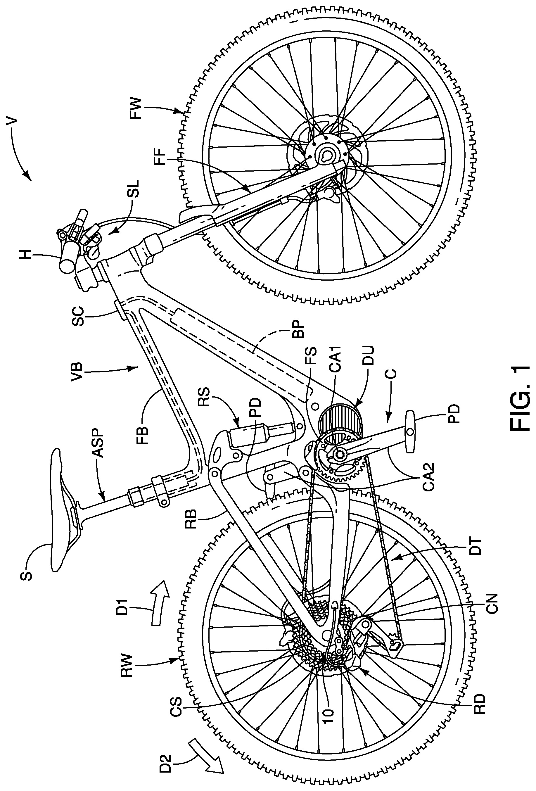
is a side elevational view of a human-powered vehicle (i.e., bicycle) equipped with a hub assembly (i.e., a bicycle hub assembly) in accordance with a first embodiment;
is a longitudinal elevational view of the hub assembly attached to the vehicle body of the human-powered vehicle illustrated in ;
is a perspective view of the hub assembly illustrated in ;
is a perspective view of the hub assembly illustrated in but in which selective part have been removed to show the bearing spacer;
is a longitudinal cross-sectional view of the hub assembly illustrated in to 4 as seen along section line 5 - 5 in ;
is an enlarged cross-sectional view of a first portion of the hub assembly illustrated in ;
is an enlarged cross-sectional view of a second portion of the hub assembly illustrated in ;
is a perspective view of the hub assembly illustrated in to 5 in which selected portions of the hub broken away;
is an end elevational view of the hub assembly illustrated in to 5 in which selected part of the hub have been removed;
is a partial exploded perspective view of the electrical assembly of the hub assembly illustrated in to 5 ;
is a partial side elevational view of an end portion of the hub assembly illustrated in to 5 in which the cable is at least partly restrained in an angled position with respect to the rotational center axis of the hub assembly where the cable protector is in a second (restricting) position;
is a longitudinal cross-sectional view of the end portion illustrated in in which where the cable protector is in the second (restricting) position;
is a partial side elevational view of the end portion illustrated in but where the cable protector is in a first (non-restricting) position in which the cable is free to be moved parallel to the rotational center axis of the hub assembly;
is a longitudinal cross-sectional view of the end portion illustrated in to 13 where the cable protector is in the first (non-restricting) position;
is a perspective view of the end portion illustrated in to 14 but where the cable protector is in the first (non-restricting) position;
is a partial end elevational view of the end portion illustrated in to 15 where the cable protector is in the first (non-restricting) position;
is a perspective view of the end portion illustrated in to 16 but where the cable protector is in the second (restricting) position;
is a partial end elevational view of the end portion illustrated in to 17 where the cable protector is in the second (restricting) position;
is a partial top view of the end portion illustrated in to 18 in which the cable is at least partly restrained in an angled position with respect to the rotational center axis of the hub assembly where the cable protector is in the second (restricting) position;
is an enlarged end elevational view of the end cap of the hub assembly illustrated in to 5 in which the cable protector is in the first (non-restricting) position;
is an enlarged top view of the end cap illustrated in in which the cable protector is in the first (non-restricting) position;
is a longitudinal cross-sectional view of the end cap illustrated in in which the cable protector is in the first (non-restricting) position;
is an enlarged end elevational view of the end cap illustrated in to 22 but in which the cable protector is in the second (restricting) position;
is an enlarged top view of the end cap illustrated in to 23 in which the cable protector is in the second (restricting) position;
is an enlarged perspective view of the end cap illustrated in to 24 in which the cable protector is in the second (restricting) position; and
is an enlarged perspective view of the end cap illustrated in to 25 in which the cable protector has been detached from the end cap.
DETAILED DESCRIPTION OF EMBODIMENTS
Selected embodiments will now be explained with reference to the drawings. It will be apparent to those skilled in the human-powered vehicle field (e.g., the bicycle field) from this disclosure that the following descriptions of the embodiments are provided for illustration only and not for the purpose of limiting the invention as defined by the appended claims and their equivalents.
Referring initially to , a hub assembly 10 is provided to a human-powered vehicle V. In other words, the human-powered vehicle V (i.e., a bicycle) is illustrated that is equipped with the hub assembly 10 in accordance with an illustrated embodiment. Here, in the illustrated embodiment, the hub assembly 10 is a bicycle hub. More specifically, the hub assembly 10 is a bicycle rear hub. Also, here, in the illustrated embodiment, the hub assembly 10 is a hub dynamo for providing electric power to one or more components of the human-powered vehicle V. However, the hub assembly 10 is not limited to a hub dynamo. In particular, certain aspects of the hub assembly 10 can be provided that does not generate electric power. Also, while the hub assembly 10 is illustrated as a rear hub, certain aspects of the hub assembly 10 can be provided to a front hub. Thus, the hub assembly 10 is not limited to a rear hub.
Here, the human-powered vehicle V is an electric assist bicycle (E-bike). Alternatively, the human-powered vehicle V can be a road bicycle, a city bike, a cargo bike, and a recumbent bike, or another type of off-road bicycle such as a cyclocross bicycle. As seen in , the human-powered vehicle V includes a vehicle body VB that is supported by a rear wheel RW and a front wheel FW. The vehicle body VB basically includes a front frame body FB and a rear frame body RB (a swing arm). The vehicle body VB is also provided with a handlebar H and a front fork FF for steering the front wheel FW. The rear frame body RB is swingably mounted to a rear section of the front frame body FB such that the rear frame body RB can pivot with respect to the front frame body FB. The rear wheel RW is mounted to a rear end of the rear frame body RB. A rear shock absorber RS is operatively disposed between the front frame body FB and rear frame body RB. The rear shock absorber RS is provided between the front frame body FB and the rear frame body RB to control the movement of the rear frame body RB with respect to the front frame body FB. Namely, the rear shock absorber RS absorbs shock transmitted from the rear wheel RW. The rear wheel RW is rotatably mounted to the rear frame body RB. The front wheel FW is mounted to the front frame body FB via the front fork FF. Namely, the front wheel FW is mounted to a lower end of the front fork FF. A height adjustable seatpost ASP is mounted to a seat tube of the front frame body FB in a conventional manner and supports a bicycle seat or saddle S in any suitable manner. The front fork FF is pivotally mounted to a head tube of the front frame body FB. The handlebar H is mounted to an upper end of a steering column or a steerer tube of the front fork FF. The front fork FF absorbs shock transmitted from the front wheel FW. Preferably, the rear shock absorber RS and the front fork FF are electrically adjustable suspensions. For example, the stiffness and/or stoke length of the rear shock absorber RS and the front fork FF can be adjusted.
The human-powered vehicle V further includes a drivetrain DT and an electric drive unit DU that is operatively coupled to the drivetrain DT. Here, for example, the drivetrain DT is a chain-drive type that includes a crank C, a front sprocket FS, a plurality of rear sprockets CS and a chain CN. The crank C includes a crank axle CA 1 and a pair of crank arms CA 2 . The crank axle CA 1 is rotatably supported to the front frame body FB via the electric drive unit DU. The crank arms CA 2 are provided on opposite ends of the crank axle CA 1 . A pedal PD is rotatably coupled to the distal end of each of the crank arms CA 2 . The drivetrain DT can be selected from any type, and can be a belt-drive type or a shaft-drive type.
The electric drive unit DU has an electric motor that provides a drive assist force to the front sprocket FS. The electric drive unit DU can be actuated to assist in the propulsion of the human-powered vehicle V in a conventional manner. The electric drive unit DU is actuated, for example, in accordance with a human driving force applied to the pedals PD. The electric drive unit DU is actuated by electric power supplied from a main battery pack BP that is mounted on a downtube of the human-powered vehicle V. The main battery pack BP can provide electrical power to other vehicle components such as the rear derailleur RD, the height adjustable seatpost ASP, the rear shock absorber RS, the front fork FF and any other vehicle component that uses electrical power.
The human-powered vehicle V further includes a cycle computer SC. Here, the cycle computer SC is mounted to the front frame body FB. Alternatively, the cycle computer SC can be provided on the handlebar H. The cycle computer SC notifies the rider of various traveling and/or operating conditions of the human-powered vehicle V. The cycle computer SC can also include various control programs for automatically controlling one or more vehicle components. For example, the cycle computer SC can be provided with an automatic shifting program for changing gears of the rear derailleur RD based on one or more traveling and/or operating conditions of the human-powered vehicle V.
Here, the human-powered vehicle V further includes a rear derailleur RD that is attached to the rear frame body RB for shifting the chain CN between the rear sprockets CS. The rear derailleur RD is one type of gear changing device. Here, the rear derailleur RD is an electric derailleur (i.e., an electric gear changing device or an electric transmission device). Here, the rear derailleur RD is provided on the rear side of the rear frame body RB near the hub assembly 10 . The rear derailleur RD can be operated when a rider of the human-powered vehicle V manually operates a gear shift operating device or shifter SL. The rear derailleur RD can also be automatically operated based on traveling conditions and/or operating conditions of the human-powered vehicle V. The human-powered vehicle V can further include a plurality of electronic components. Some or all of the electronic components can be supplied with electric power generated by the hub assembly 10 during a power generation state as discussed herein.
The structure of the hub assembly 10 will now be described with particular reference to to 8 . The hub assembly comprises a hub axle 12 and a hub body 14 . The hub axle 12 is configured to be non-rotatably attached to the vehicle body VB. In this embodiment, the hub axle 12 is configured to be non-rotatably attached to the rear frame body RB. The hub body 14 is rotatably mounted on the hub axle 12 to rotate around a rotational center axis A 1 of the hub assembly 10 . The hub axle 12 has a center axis coaxial with the rotational center axis A 1 . The hub body 14 is rotatably disposed around the rotational center axis A 1 . In other words, the hub body 14 is rotatably mounted around the hub axle 12 .
As seen in to 7 , the hub axle 12 is a rigid member made of a suitable material such as a metallic material. The hub axle 12 has a first axial end 12 a and a second axial end 12 b . Here, the hub axle 12 is a tubular member. Thus, the hub axle 12 has an axial bore 12 c that extends between the first axial end 12 a and the second axial end 12 b . The hub axle 12 can be a one-piece member or made of several pieces. Here, the hub axle 12 is provided with a first end piece or end cap 16 and a second end piece or end cap 18 . The first end cap 16 is mounted to the first axial end 12 a (left side in to 8 ) of the hub axle 12 , and the second end cap 18 is mounted to the second axial end 12 b (right side in to 8 ) of the hub axle 12 . For example, the first end cap 16 is threaded on the first axial end 12 a of the hub axle 12 , and the second end cap 18 is secured to the second axial end 12 b of the hub axle 12 by a fixing bolt 20 that is threaded into the axial bore 12 c of the hub axle 12 . In this way, the first end cap 16 and the fixing bolt 20 are received in mounting openings of the rear frame body RB as seen in .
The hub assembly 10 further comprises a rotation restriction part 21 that is configured to be disposed between the hub axle 12 and a frame (the rear frame body RB) of the human-powered vehicle V so that rotation of the hub axle 12 relative to the frame (the rear frame body RB) is restricted. Here, the second end cap 18 includes the rotation restriction part 21 which is also received in one of the mounting openings of the rear frame body RB. The rotation restriction part 21 engages the rear frame body RB so that rotation of the hub axle 12 relative to the rear frame body RB is restricted. The second end cap 18 is detachably attached to the hub axle 12 using the fixing bolt 20 . Thus, the rotation restriction part 21 is detachably attached to the hub axle 12 .
Here, as seen in , the hub assembly 10 further comprises a wheel holding mechanism 22 for securing the hub axle 12 of the hub assembly 10 to the rear frame body RB. The wheel holding mechanism 22 basically includes a shaft or skewer 22 a , a cam body 22 b , a cam lever 22 c and an adjusting nut 22 d . The cam lever 22 c is attached to one end of the skewer 22 a via the cam body 22 b , while the adjusting nut 22 d is threaded on the other end of the skewer 22 a . The cam lever 22 c is attached to the cam body 22 b . The cam body 22 b is coupled between the skewer 22 a and the cam lever 22 c to move the skewer 22 a relative to the cam body 22 b . Thus, the cam lever 22 c is operated to move the skewer 22 a in the axial direction of the rotational center axis A 1 with respect to the cam body 22 b to change the distance between the cam body 22 b and the adjusting nut 22 d . Preferably, a compression spring is provided at each end of the skewer 22 a . The wheel holding mechanism 22 is sometimes called a quick release skewer. The wheel holding mechanism 22 is typically used with a frame having a pair of U-shaped axle attachments that each have an open-ended slot for receiving a portion of the skewer 22 a . Alternatively, the hub axle 12 can be non-rotatably attached to the rear frame body RB with other attachment structures as needed and/or desired.
As indicated in , 3 and 4 , the hub body 14 is rotatably mounted around the hub axle 12 to rotate in a driving rotational direction D 1 . The driving rotational direction D 1 corresponds to a forward driving direction of the rear wheel RW. The hub body 14 is configured to support the rear wheel RW in a conventional manner. More specifically, in the illustrated embodiment, the hub body 14 includes a first outer flange 14 a and a second outer flange 14 b . The first outer flange 14 a and the second outer flange 14 b extend radially outward with respect to the rotational center axis A 1 from a peripheral surface of the hub body 14 . The first outer flange 14 a and the second outer flange 14 b are configured to receive a plurality of spokes ( ) for attaching a rim ( ) of the rear wheel RW to the hub body 14 . In this way, the hub body 14 and the rear wheel RW are coupled to rotate together.
As seen to 7 , the hub assembly 10 further comprises a first hub body bearing 24 . The first hub body bearing 24 rotatably supports the hub body 14 . Preferably, the hub assembly 10 further comprises a second hub body bearing 26 rotatably supporting an end of the hub body 14 . The first hub body bearing 24 rotatably supports the other end of the hub body 14 with respect to the rotational center axis A 1 . The first hub body bearing 24 includes a first inner race 24 a , a first outer race 24 b and a plurality of first roller elements 24 c . The first roller elements 24 c are disposed between the first inner race 24 a and the first outer race 24 b . The second hub body bearing 26 includes a second inner race 26 a , a second outer race 26 b and a plurality of second roller elements 26 c . The second roller elements 26 c are disposed between the second inner race 26 a and the second outer race 26 b . The first hub body bearing 24 and the second hub body bearing 26 are radial ball bearings. Radial ball bearings support force in the direction perpendicular to the axis. Further, a radial roller bearing can be adopted instead of the radial ball bearing. Radial roller bearings include cylindrical roller bearings and needle roller bearings.
Here, the hub assembly 10 further comprises a bearing spacer 28 . The bearing spacer 28 is provided on the hub axle 12 and supports the hub body 14 via the second hub body bearing 26 . The bearing spacer 28 supports the second hub body bearing 26 . The bearing spacer 28 has an inner peripheral end 28 a provided to the hub axle 12 and an outer peripheral end 28 b spaced radially outward of the inner peripheral end 28 in a radial direction with respect to the rotational center axis A 1 . The second hub body bearing 26 is disposed at the outer peripheral end 28 b of the bearing spacer 28 and rotatably supports the hub body 14 . The bearing spacer 28 is non-rotatable with respect to the hub axle 12 . In particular, as seen in , the inner peripheral end 28 a defines a non-circular opening 28 a 1 that mates with a non-circular portion of the hub axle 12 to non-rotatably couple the bearing spacer 28 with respect to the hub axle 12 . The axial position of the bearing spacer 28 with respect to the hub axle 12 can be determined by being sandwiched between a step provided on the hub axle 12 and a nut screwed to the hub axle 12 . Here, the bearing spacer 28 includes an axial opening 28 c.
Here, the hub assembly 10 further comprises a sprocket support structure 30 . In the illustrated embodiment, the sprocket support structure 30 supports the rear sprockets CS as seen in . The sprocket support structure 30 is rotatably disposed around the rotational center axis A 1 to transmit a driving force to the hub body 14 while rotating in a driving rotational direction around the rotational center axis A 1 . As explained below, the sprocket support structure 30 does not transmit a driving force to the hub body 14 while rotating in a non-driving rotational direction D 2 around the rotational center axis A 1 . The non-driving rotational direction D 2 is opposite to the driving rotational direction D 1 with respect to the rotational center axis A 1 . The rotational center axis of the sprocket support structure 30 is disposed concentrically with the rotational center axis A 1 of the hub assembly 10 .
While the sprocket support structure 30 is configured to non-rotatably support the rear sprockets CS, the sprocket support structure 30 is not limited to the illustrated embodiment. Alternatively, one or more of the rear sprockets CS can be integrally formed with the sprocket support structure 30 . In any case, the sprocket support structure 30 and the rear sprockets CS are coupled together to rotate together in both the driving rotational direction D 1 and the non-driving rotational direction D 2 .
The hub assembly 10 further comprises a first sprocket support bearing 32 and a second sprocket support bearing 34 . The first sprocket support bearing 32 rotatably supports a first end 30 a of the sprocket support structure 30 . The second sprocket support bearing 34 rotatably supports a second end 30 b of the sprocket support structure 30 . The first sprocket support bearing 32 and the second sprocket support bearing 34 have outer diameters that are smaller than the outer peripheral end 28 b of the bearing spacer 28 . The inner diameter of the first sprocket support bearing 32 is larger than the inner diameter of the second sprocket support bearing 34 . Thus, the first sprocket support bearing 32 and the second sprocket support bearing 34 can be mounted on the hub axle 12 from the second axial end 12 b of the hub axle 12 . The first sprocket support bearing 32 includes a first inner race 32 a , a first outer race 32 b and a plurality of first roller elements 32 c . The first roller elements 32 c are disposed between the first inner race 32 a and the first outer race 32 b . The second sprocket support bearing 34 includes a second inner race 34 a , a second outer race 34 b and a plurality of second roller elements 34 c . The second roller elements 34 c are disposed between the second inner race 34 a and the second outer race 34 b . Here, the first sprocket support bearing 32 and the second sprocket support bearing 34 are radial ball bearings. Radial ball bearings support force in the direction perpendicular to the axis. Further, a radial roller bearing can be adopted instead of the radial ball bearing. Radial roller bearings include cylindrical roller bearings and needle roller bearings. A tubular spacing element 35 is disposed between the first sprocket support bearing 32 and the second sprocket support bearing 34 .
As seen in to 7 , the hub assembly 10 further comprises an electrical assembly 36 . The electrical assembly 36 comprises an electric component 38 . Thus, the hub assembly 10 further comprises the electric component 38 . The electric component 38 is non-rotatably disposed with respect to the hub axle 12 , and the cable 40 is an electric cable electrically connected to the electric component. While the electric component 38 is part of the hub assembly 10 , the electric component 38 can be used with other components of the human-powered vehicle. The electric component 38 has an opening 38 a for receiving the hub axle 12 therethrough. Thus, the electric component 38 is supported on the hub axle 12 . As explained later, the electric component 38 is non-rotatably disposed on the hub axle 12 .
The hub assembly 10 further comprises a cable 40 . As seen in , the cable 40 enters the hub assembly 10 thorough an opening 18 a of the end cap 18 . Here, as seen in , the cable 40 is an electric cable that is electrically connected to the electric component 38 . The cable 40 has a first end 40 a and a second end 40 b . The cable 40 has a longitudinal axis C 1 that extend between the first end 40 a and the second end 40 b . The first end 40 a is spaced from the second end 40 b by an intermediate section 40 c of the cable 40 . The first end 40 a is electrically connected to the electric component 38 . The second end 40 b is electrically connected to another electric component of the human-powered vehicle V such as the rear derailleur RD, the battery pack BP or an electrical junction. Here, the second end 40 b is an electrical connector.
Also, the cable 40 has a first portion 40 d that is disposed inside of the hub assembly 10 and a second portion 40 e disposed outside of the hub assembly 10 . Basically, the first portion 40 d of the cable 40 is at least partly extending along the rotational center axis A 1 . In other words, the first portion 40 d of the cable at least partly extends substantially parallel to the rotational center axis A 1 . The cable 40 extends outside of the hub assembly 10 through the opening 18 a of the end cap 18 . Thus, the second portion 40 e of the cable 40 corresponds to the portion of the cable 40 exiting the opening 18 a of the end cap 18 , while the first portion 40 d corresponds to the cable 40 that is not exposed from the hub assembly 10 . Here, the opening 18 a of the end cap 18 has a center axis B 1 that is parallel to the center rotational axis A 1 of the hub assembly 10 . The opening 18 a can have a central axis B 1 along the central rotation axis A 1 . Here, in the illustrated embodiment, the rotation restriction part 21 includes a cable guide structure 21 a that configured to guide the second portion 40 e of the cable 40 in an angled direction with respect to the rotational center axis A 1 . Also, in the illustrated embodiment, the cable guide structure 21 a is further configured to guide the cable 40 in a radial direction of the hub axle 12 . Preferably, the cable guide structure 21 a includes a groove 21 b that is configured to guide the cable 40 .
Preferably, as in the illustrated embodiment, the cable 40 is disposed in an axially extending recess or groove 12 d of the hub axle 12 as seen in . Thus, the groove 12 d constitutes a cable receiving passageway for the cable 40 . The groove 12 d , for example, extends from the second axial end 12 b to inside the housing 42 of the electric component 38 . In this way, cable 40 can be located in the groove 12 d between the electric component 38 and the second axial end 12 b of the hub axle 12 . Here, the groove 12 d extends from the second axial end 12 b past the electric power generator 60 .
The hub assembly 10 further comprises a cable protector 41 . Basically, the cable protector 41 is disposed on the hub axle 12 . In other words, the cable protector 41 is connected to the hub axle 12 . More specifically, the cable protector 41 is disposed on the end cap 18 . Even more specifically, the cable protector 41 is disposed on the rotation restriction part 21 of the end cap 18 . The cable protector 41 is movably arranged with respect to the hub axle 12 between a first position and a second position. The second portion 40 e of the cable 40 extends along the rotational center axis A 1 where the cable protector 41 is in the first position. In other words, the second portion 40 e of the cable 40 is configured to extend along an axis that is parallel to the rotational center axis A 2 in a state in which the cable protector 41 is in the first position. The second portion 40 e of the cable 40 is at least partly restrained in an angled position with respect to the rotational center axis A 1 where the cable protector 41 is in the second position. In the illustrated embodiment, the cable protector 41 is used with the hub axle 12 which has a quick release skewer (the wheel holding mechanism 22 ). Here, the rear frame body RB has a pair of U-shaped axle attachments that each have an open-ended slot for receiving a portion the skewer 22 a . In other words, when the hub assembly 10 is used with a quick release skewer, there is nothing other than the cable protector 41 in the axial direction when the wheel is attached to the rear frame body RB to restrict outward movement of the cable 40 . Therefore, in this type of the quick release arrangement, the cable protector 41 is particularly useful in order to maintain the cable 40 in a bent position when the cable protector 41 is in the second position.
In the illustrated embodiment, the cable protector 41 is pivotally mounted with respect to the hub axle 12 between the first position and the second position. Thus, the cable protector 41 has a pivot axis P 1 . The pivot axis P 1 extends in a twisted or intersecting relationship with respect to the rotational center axis A 1 of the hub body 14 . Thus, the pivot axis P 1 is not parallel to the rotational center axis A 1 of the hub body 14 . Here, the pivot axis P 1 is perpendicularly arranged relative to the rotational center axis A 1 .
Here, the cable protector 41 is a wire rod. The wire rod of the cable protector 41 has a first end 41 a and a second end 41 b . The first end 41 a and the second end 41 b are coupled to the rotation restriction part 21 of the end cap 18 . More specifically, the cable protector 41 is attached inside the groove 21 b of the cable guide structure 21 a . Preferably, the rotation restriction part 21 further includes a pair of recesses 21 c and a pair of recesses 21 d that cooperate with the cable protector 41 as discussed below.
Also, the cable protector 41 further includes a cable restricting portion 41 c that is wider than a width of the cable 40 . The cable restricting portion 41 c is configured to contact the second portion 40 e of the cable 40 where the cable protector 41 is in the second position. The cable restricting portion 41 c is also wider than a transverse width of the groove 21 b of the cable guide structure 21 a . The cable protector 41 has a first leg portion 41 d and a second leg portion 41 e . The cable protector 41 is maintained in the second position when each of the leg portions 41 d and 41 e engages with one of the recesses 21 c . The first leg portion 41 d and the second leg portion 41 e are configured to engage the cable guide structure 21 a so that the cable protector 41 can be maintained in either the first position or the second position by a spring force of the first leg portion 41 d and the second leg portion 41 e . Namely, the cable protector 41 can be maintained in either the first position or the second position in an overridable manner. In particular, to install and or uninstall the cable protector 41 in the recesses 21 c of the rotation restriction part 21 , the cable protector 41 is resiliently deformed as the cable protector 41 moves into and out of the recesses 21 c of the rotation restriction part 21 .
Here, the rotation restriction part 21 includes a recess (e.g., the recesses 21 c ), and the cable protector 41 , which is releasably retained in the recess (e.g., the recesses 21 c ) where the cable protector 41 is in the second position. In other words, at least one recess is proved to the rotation restriction part 21 to releasably retain the cable protector 41 in the second position. On the other hand, the recesses 21 d pivotally couple the cable protector 41 to the rotation restriction part 21 . In particular, the first end 41 a of the cable protector 41 is disposed in one of the recesses 21 d , and the second end 41 b is disposed in the other one of the recesses 21 d . The first end 41 a and the second end 41 b define a pivot axis P 1 for the cable protector 41 . Since the recesses 21 d are elongated slots in the illustrated embodiment, the pivot axis P 1 may not be fixed relative to the rotation restriction part 21 . Rather, it is possible for the pivot axis P 1 to shift along the recesses 21 d . However, in a case where each of the leg portions 41 d and 41 e engages one of the recesses 21 c , the shift of the cable protector 41 along the recesses 21 d is restricted. Further, a recess or a hole into which the first end 41 a and the second end 41 b are inserted can be provided in the recess 21 d . This configuration restricts the shift of the cable protection member 41 along the recess 21 d . The cable protector 41 is attached to the recess 21 d without being deformed. However, the cable protector 41 can be attached to the recess 21 d in a deformed state.
Here, as seen in , the recesses 21 c are located on opposite sides of the groove 21 b of the cable guide structure 21 a . Each of the recesses 21 c is located on one of surfaces of the groove 21 b facing each other so as to sandwich the cable 40 . Likewise, the recesses 21 d are also located on opposite sides of the groove 21 b of the cable guide structure 21 a . Each of the recesses 21 d is located on one of surfaces of the groove 21 b facing each other so as to sandwich the cable 40 . Further, on each side of the groove 21 b , the corresponding ones of the recesses 21 c and the recesses 21 d are aligned. With this configuration, the first end 41 a is disposed on a first side of a reference plane RP, and the second end 41 b is disposed on a second side of the reference plane RP in a case where the reference plane RP entirely contains the rotational center axis A 1 , and is perpendicular to the pivot axis P 1 of the cable protector 41 . In other words, when the cable protector 41 is in the first (non-restricting) position as seen in , 16 , 21 and 22 , the first end 41 a is disposed in the recess 21 d on the first side of the reference plane RP, and the second end 41 b is disposed in the recess 21 d on the second side of the reference plane RP. In this way, in the first (non-restricting) position, the cable protector 41 can be freely moved relative to the rotation restriction part 21 while the first end 41 a and the second end 41 b are in the recesses 21 d . When the cable protector 41 is in the second (restricting) position as seen in , 18 and 23 to 25 , the first end 41 a and the second end 41 b are disposed in the recesses 21 d , and the leg portions 41 d and 41 e are disposed in the recesses 21 c . In this way, in the second (restricting) position, the movement of the cable protector 41 is restricted relative to the rotation restriction part 21 . In the illustrated embodiment, the recesses 21 c are mirror images of each other with respect to the reference plane RP. Likewise, the recess 21 d are mirror images of each other with respect to the reference plane RP. The recesses 21 c and the recess 21 d have openings that are in direct communication with the groove 21 b of the cable guide structure 21 a . The recesses 21 c and the recess 21 d each have a width extending in a direction parallel to the rotational center axis A 1 of the hub body 14 where the widths are equal to or slightly larger than the diameter of the wire that forms the cable protector 41 .
Here, the electric component 38 includes a housing 42 . The housing 42 is configured to define the opening 38 a of the electric component 38 that receives the hub axle 12 . The housing 42 has a first surface 42 a , a second surface 42 b and the opening 38 a . The opening 38 a extends from the first surface 42 a to the second surface 42 b . The second surface 42 b is located on the opposite side of the electric component 38 with respect to the first surface 42 a . In the illustrated embodiment, the first surface 42 a faces the first axial end 12 a of the hub axle 12 , while the second surface 42 b faces the second axial end 12 b of the hub axle 12 . Here, the hub axle 12 extends through the opening 38 a of the electric component 38 .
Here, the electric component 38 further comprises a spacer 43 that is provided between the hub axle 12 and the electric component 38 in a radial direction with respect to the rotational center axis A 1 . In other words, the hub assembly 10 further comprises the spacer 43 provided between the hub axle 12 and the electric component 38 in a radial direction with respect to the rotational center axis A 1 . The spacer 43 is a tubular support having a cylindrical guide portion 43 a and an annular abutment portion 43 b . The guide portion 43 a is included in the spacer 43 .
Also, the electric component 38 includes an electric circuit board 44 . The electric component 38 is disposed in the hub body 14 . Thus, the electric circuit board 44 is disposed in the housing 42 . The electric cable 40 is electrically connected to the electric circuit board 44 . Specifically, the first end 40 a of the cable 40 is electrically connected to the electric circuit board 44 .
As seen in , the cable 40 enters the hub assembly 10 thorough an opening 18 a of the end cap 18 . Then, the cable 40 extends axially along the hub axle 12 and passes through the bearing spacer 28 . The cable 40 enters the housing 42 of the electric component 38 through the lid 46 .
In the illustrated embodiment, the housing 42 includes a housing body 45 and a lid 46 . The lid 46 is attached to the housing body 45 for enclosing the electric circuit board 44 in the housing 42 . Here, the lid 46 is bonded to the housing body 45 by adhesive or welding. However, the lid 46 can be attached to the housing body 45 by threaded fastener, rivets, etc. Preferably, the housing body 45 and the lid 46 are rigid members made from a suitable material. For example, the housing body 45 and the lid 46 are made of a resin material. For example, the housing body 45 and the lid 46 can each be injected molded members. In the illustrated embodiment, the bearing spacer 28 is fixedly attached to the housing 42 by a plurality of threaded fasteners 47 . The threaded fasteners 47 are threaded into the lid 46 of the housing 42 .
The housing 42 is non-rotatable with respect to the hub axle 12 . In the illustrated embodiment, the electric circuit board 44 is disposed in the housing 42 , which is non-rotatable with respect to the hub axle 12 . The housing 42 is configured to house the electric circuit board 44 as well as other items elements. In particular, the housing 42 has an outer peripheral surface defining an internal space 42 c in which the electric circuit board 44 is disposed. The first surface 42 a of the housing 42 includes a plurality of keying protrusions 42 d . As described later, the keying protrusions 42 d can be provided to engage a non-rotatable member that is provided to the hub axle 12 for non-rotatably coupling the housing 42 to the hub axle 12 .
As seen in to 8 and 10 , the lid 46 is coupled to the housing body 45 to protect the electric circuit board 44 and other parts contained in the housing 42 . The lid 46 overlies the internal space 42 c of the housing body 45 . Thus, at least the housing 42 , the electric circuit board 44 and the capacitor 54 can be considered to constitute an electrical unit that is disposed in the hub body 14 . The internal space 42 c has a donut shape in that the hub axle 12 passes through a center area of the housing 42 . In this way, the electric circuit board 44 is non-rotatable with respect to the hub axle 12 . The electric circuit board 44 is disposed perpendicular to the rotational center axis A 1 . The electric circuit board 44 is a part of the electric component 38 .
As seen in , in the illustrated embodiment, the electric circuit board 44 has an arc shape. Here, the electric circuit board 44 has a first circumferential end portion 44 a and a second circumferential end portion 44 b . The electric circuit board 44 also has at least one arc shaped edge extending at least partly from the first circumferential end portion 44 a to the second circumferential end portion 44 b . Here, the at least one arc shaped edge includes at least one of an inner arc shaped edge 44 c and an outer arc shaped edge 44 d with respect to the rotational center axis A 1 . The electric circuit board 44 further includes an electronic controller 48 that provided on the electric circuit board 44 . The electronic controller 48 is configured to receive a detection signal from the rotation detection sensor 52 . The electronic controller 48 includes at least one processor that executes predetermined control programs. The at least one processor can be, for example, a central processing unit (CPU) or a micro processing unit (MPU). The term “electronic controller” as used herein refers to hardware that executes a software program, and does not include a human. Preferably, the electric circuit board 44 further includes a data storage device (memory) that provided on the electric circuit board 44 . The data storage device (memory) stores various control programs and information used for various control processes including power generation control, power storage control, hub rotation detection control, etc. The data storage device includes any computer storage device or any non-transitory computer-readable medium with the sole exception of a transitory, propagating signal. For example, the data storage device includes a nonvolatile memory and a volatile memory. The nonvolatile memory includes, for example, at least one of a read-only memory (ROM), an erasable programmable read only memory (EPROM), an electrically erasable programmable read-only memory (EEPROM), and a flash memory. The volatile memory includes, for example, a random access memory (RAM).
As seen in , the hub assembly 10 further comprises a detected part 50 coupled to the sprocket support structure 30 . In particular, the detected part 50 is fixed to the sprocket support structure 30 so that the detected part 50 and the sprocket support structure 30 rotate together about the hub axle 12 . The hub assembly 10 further comprises a rotation detection sensor 52 that is configured to detect the detected part 50 to detect rotation of the sprocket support structure 30 around the rotational center axis A 1 . The rotation detection sensor 52 is disposed in the hub body 14 . In other words, the rotation detection sensor 52 is configured to detect the detected part 50 that is provided to the sprocket support structure 30 . In particular, the rotation detection sensor 52 is provided in the internal space 42 c of the housing 42 . In this way, the rotation detection sensor 52 is non-rotatably mounted to the hub axle 12 . Thus, the rotation detection sensor 52 does not rotate with the hub body 14 . The rotation detection sensor 52 is also a part of the electric component 38 . The rotation detection sensor 52 is electrically connected to the electric circuit board 44 . As seen in , the rotation detection sensor 52 is disposed in the hub body 14 at a location spaced radially outward from the hub axle 12 .
As seen in to 10 , the rotation detection sensor 52 is disposed at a position that is axially aligned within the axial opening 28 c of the bearing spacer 28 . In this way, the bearing spacer 28 does not interfere with the rotation detection sensor 52 detecting the detected part 50 that is provided to the sprocket support structure 30 . As seen in to 10 , the rotation detection sensor 52 disposed at a position separated from the electric circuit board 44 . In particular, the rotation detection sensor 52 is arranged at a position separated from the electric circuit board 44 in a direction parallel to the rotational center axis A 1 . The rotation detection sensor 52 is electrically connected to the electric circuit board 44 .
In the illustrated embodiment, the rotation detection sensor 52 includes a magnetic sensor, and the detected part 50 includes a magnet. Thus, the magnetic sensor detects movement of the magnet, which rotates together with the sprocket support structure 30 . In other words, with this arrangement, the rotation detection sensor 52 is configured to detect the detected part 50 to detect rotation of the sprocket support structure 30 around the rotational center axis A 1 . The electronic controller 48 is configured to receive a detection signal from the rotation detection sensor 52 .
Here, the magnet of the detected part 50 is an annular member with alternating S-pole sections and N-pole sections. In this way, the rotation detection sensor 52 can detect a rotational amount and a rotational direction of the sprocket support structure 30 . However, the detected part 50 is not limited to the illustrated annular member. For example, the detected part 50 can be formed of a single non-annular magnet, or two or more magnets that are circumferentially spaced apart about the rotational center axis A 1 . In the case of using two or more circumferentially spaced magnets, a back yoke can be provided and the circumferentially spaced magnets can be provided to the back yoke. In this way, the circumferentially spaced magnets can be easily installed in the hub 10 . The term “sensor” as used herein refers to a hardware device or instrument designed to detect the presence or absence of a particular event, object, substance, or a change in its environment, and to emit a signal in response. The term “sensor” as used herein do not include a human.
The hub assembly 10 further comprises at least one capacitor 54 electrically connected to the electric circuit board 44 . The at least one capacitor is electrically connected to the at least one conductor. Here, the electric component 38 comprises two capacitors 54 . The capacitors 54 are examples of an electric power storage of the electric component 38 . In other words, the capacitor 54 is also a part of the electric component 38 . The capacitors 54 are preferably disposed in the housing 42 of the hub assembly 10 . Thus, the capacitors 54 are non-rotatably supported on the hub axle 12 by the housing 42 .
As explained below, an additional conductor electrically connecting the rotation detection sensor 52 and the electric circuit board 44 . Also, here, the electric component 38 comprises a first conductor 56 A and a pair of second conductors 56 B. The rotation detection sensor 52 is electrically connected to the electric circuit board 44 by the first conductor 56 A. Here, the first conductor 56 A is a flexible tape conductor. The first conductor 56 A can be an electrically conductive lead. On the other hand, the electric circuit board 44 is electrically connected to the capacitors 54 by the second conductors 56 B. The second conductors 56 B extend from one of the first circumferential end portion 44 a and the second circumferential end portion 44 b . Here, one of the second conductors 56 B extends from the first circumferential end portion 44 a to electrical connect one of the capacitors 54 to the electric circuit board 44 . The other one of the second conductors 56 B extends from the second circumferential end portion 44 b to electrical connect the other one of the capacitors 54 to the electric circuit board 44 . Here, the second conductors 56 B are flexible tape conductors. The second conductors 56 B can be an electrically conductive lead. The capacitor 54 is provided in the internal space of the housing 42 at a position other than on the electronic circuit board 44 . The capacitor 54 may be held in the housing 42 with an adhesive or the like. The lid 46 is coupled to the housing body 45 to protect the capacitors 54 that are disposed inside the housing 42 .
The electric circuit board 44 is electrically connected to the rotation detection sensor 52 and the capacitor 54 . In this way, the capacitor 54 provides electrical power to the electric circuit board 44 and other electric components electrically connected to the electric circuit board 44 . For example, the capacitor 54 provides electrical power to the rotation detection sensor 52 . Also, the electronic controller 48 of the electric circuit board 44 is configured to control the input and output of electric power from the capacitor 54 .
As seen in to 7 , the hub assembly 10 further comprises a one-way clutch 58 that is formed between the hub body 14 and the sprocket support structure 30 . The one-way clutch 58 includes a plurality of pawls 58 A disposed between the hub body 14 and the sprocket support structure 30 . The one-way clutch 58 further includes a biasing element 58 B that couples the pawls 58 A to the sprocket support structure 30 . The one-way clutch 58 further includes a plurality of ratchet teeth 58 C. The ratchet teeth 58 C are provided to a fixing ring 58 D that is fixed to the hub body 14 . The ratchet teeth 58 C are provided on the inner peripheral surface of the fixing ring 58 D. The fixing ring 58 D is screwed to the hub body 14 . The fixing ring 58 D is made of a hard material such as metal. The fixing ring 58 D abuts against the outer race 26 b of the second hub body bearing 26 in the axial direction with respect to the rotational center axis A 1 . The opposite side of the outer race 26 b of the second hub body bearing 26 in the axial direction abuts against a step formed in the hub body 14 . The outer race 26 b of the second hub body bearing 26 is restricted in axial movement by the fixing ring 58 D and the steps formed on the hub body 14 . The biasing element 58 B biases the pawls 58 A into engagement with the ratchet teeth 58 C of the fixing ring 58 D. The biasing element 58 B squeezes the pawls 58 A against the sprocket support structure 30 such that the pawls 58 A pivot towards engagement with the ratchet teeth 58 C of the fixing ring 58 D. A seal member 58 E is provided on the fixing ring 58 D. The seal member 58 E is formed in a ring shape. The tongue portion of the sealing member 58 E is in contact with the outer peripheral surface of the sprocket support 30 .
In this way, the sprocket support structure 30 is coupled to the hub body 14 to rotate together in the driving rotational direction D 1 around the rotational center axis A 1 . Also, in a case where the sprocket support structure 30 is rotated in the non-driving rotational direction D 2 , the ratchet teeth 58 C of the sprocket support structure 18 push the pawls 58 A and pivot the pawls 58 A to a retracted position against the sprocket support structure 30 . Thus, the sprocket support structure 30 is configured to rotate relative to the hub body 14 in the non-driving rotational direction D 2 around the rotational center axis A 1 . In this way, the sprocket support structure 30 and the one-way clutch 58 form a freewheel that is commonly used in bicycles. Since the basic operation of the freewheel is relatively conventional, the freewheel will not be discussed or illustrated in further detail.
As seen in to 7 , the hub assembly 10 comprises an electric power generator 60 . Here, the electric power generator 60 is considered to be part of the electrical assembly 36 . In other words, the electrical assembly 36 comprises the electric power generator 60 . The cable 40 is electrically connected the electric power generator 60 via the electric circuit board 44 . In this way, the cable 40 can provide electric power generated by the hub assembly 10 to the rear derailleur RD, the battery pack BP or another electric component. The cable 40 can also be used to transmit signals from the electronic controller 48 of the electric circuit board 44 to the rear derailleur RD or another electric component using power line communication (PLC).
The electric power generator 60 is provided to the hub body 14 , and is configured to generate electric power by rotation of the hub body 14 . More specifically, the electric power generator 60 is provided to the hub body 14 between the hub axle 12 and a center potion of the hub body 14 . In the illustrated embodiment, the hub body 14 is rotatably mounted on the axle 12 to rotate around the rotational center axis A 1 of the electric power generator 60 . The electric power generator 60 is configured to generate electric power by rotation of the hub body 14 relative to the hub axle 12 . The electronic controller 48 of the electric circuit board 44 is electrically connected to the electric power generator 60 for controlling the electric power output of the electric power generator 60 . Thus, the electric power generated by the electric power generator 60 can be stored and/or supplied directly to other components such as the rotation detection sensor 52 , the rear derailleur RD, etc.
Although the electric power generator 60 is illustrated and described as part of the hub assembly 10 , the electric power generator 60 can be applied to a different part of the human-powered vehicle V. In general, the electric power generator 60 comprises an axle, a stator and a rotor. Thus, the following description of the electric power generator 60 is not limited to being used as part of the hub assembly. Rather, the following description of the electric power generator 60 can be adapted to other parts of the human-powered vehicle V for generating electricity.
In the illustrated embodiment, the electric power generator 60 further includes a stator 62 and a rotor 64 . The stator 62 is non-rotatable with respect to the hub axle 12 . On the other hand, the rotor 64 is rotatably mounted on the hub axle 12 to rotate around a rotational center axis A 1 of the electric power generator 60 . In particular, the rotor 64 is provided to the hub body 14 so as to rotate with the hub body 14 . Thus, when the hub body 14 rotates with respect to the hub axle 12 , the rotor 64 rotates with respect to the stator 62 for power generation. Namely, an induced electromotive force is generated on the stator 62 by the rotation of the rotor 64 and an electrical current flow out of the stator 62 of the electric power generator 60 . As seen in , 9 and 10 , the electrical current from the stator 62 is supplied to the electric component 38 via a pair of electrical wires W 1 and W 2 . The electrical wires W 1 and W 2 are electrically connected to the electric circuit board 44 . Here, the electrical wires W 1 and W 2 extend though openings in an end wall portion of the housing 42 , and then passes through the electric power generator 60 . As seen in , the electrical wires W 1 and W 2 are electrically connected to the electric circuit board 44 . As seen in , the stator 62 has a pair of electrical wires W 3 and W 4 . The electrical wire W 3 is electrically connected to the electrical wire W 1 , and the electrical wire W 4 is electrically connected to the electrical wire W 2 .
As seen in , the stator 62 has a first axial stator-end 68 A that faces the first axial end 12 a of the axle 12 with respect to the rotational center axis A 1 and a second axial stator-end 68 B that faces the second axial end 12 b of the axle 12 with respect to the rotational center axis A 1 . Here, the stator 62 includes an armature that is disposed on the axle 12 . The armature of the stator 62 includes a winding coil 62 A and a bobbin 62 B.
The winding coil 62 A is wound on the bobbin 62 B for supporting the winding coil 62 A. The winding coil 62 A is made of a conductive metal wire material, such as a copper wire or an aluminum alloy wire. The electrical wires W 3 and W 4 are electrically connected to both ends of the winding coil 62 A. The electrical wire W 3 is electrically connected to the electrical wire W 1 by a first electrical connector EC 1 . The electrical wire W 4 is electrically connected to the electrical wire W 2 by a second electrical connector EC 2 . In this way, electric power generated in the winding coil 62 A is transmitted to the electric circuit board 44 of the electric component 38 via the electrical wires W 1 , W 2 , W 3 and W 4 . The electric circuit board 44 then regulates the electric power received from the winding coil 62 A to selectively store the electric power in the capacitors 54 and/or to selectively transmit the electric power outside of the hub assembly 10 via the cable 40 as explained below.
The bobbin 62 B is non-rotatably coupled to the hub axle 12 . The bobbin 62 B has a cylindrical trunk portion, a first flange portion and a second flange portion. The cylindrical trunk portion has an outside circumference on which the winding coil 62 A is wound. The first flange portion and the second flange portion are formed on both axial end portions of the cylindrical trunk portion.
In the illustrated embodiment, the housing 42 is disposed between the sprocket support structure 30 and the stator 62 . The first surface 42 a faces the second axial stator-end 68 B of the stator 62 . The first surface 42 a is formed by the exterior surface of the end wall portion of the housing 42 . Preferably, the housing 42 is disposed adjacent to the stator 62 at the second axial stator-end 68 B of the stator 62 in the axial direction with respect to the rotational center axis A 1 .
Here, the electric circuit board 44 is disposed adjacent the stator 62 at the second axial stator-end 68 B of the stator 62 in the axial direction with respect to the rotational center axis A 1 . The electrical wires W 1 and W 2 are connected to the electric circuit board 44 . In particular, the electric circuit board 44 has a first axially facing surface 44 e facing the stator 62 and a second axially facing surface 44 f facing away from the stator 62 . Here, the electrical wires W 1 and W 2 are electrically connected to the second axially facing surface 44 f of the electric circuit board 44 .
The armature of the stator 62 further includes a plurality of first yoke 62 C and a plurality of second yoke 62 D. The first yokes 62 C are arranged in the circumferential direction of the hub axle 12 . Likewise, the second yokes 62 D are arranged in the circumferential direction of the hub axle 12 and alternate with the first yokes 62 C. The winding coil 62 A is located between the first yokes 62 C and the second yokes 62 D in the axial direction of the hub axle 12 . Here, the first yokes 62 C and the second yokes 62 D are fitted to grooves of the bobbin 62 B so that the first yokes 62 C and the second yokes 62 D alternate in a circumferential direction around the rotational center axis A 1 . The first yokes 62 C and the second yokes 62 D can be attached to the bobbin 62 B by an adhesive, for example.
Each of the first yokes 62 C can be a laminated yoke made up of a plurality of laminate pieces or can be a single piece. In the case of laminated yokes, the laminate pieces of the first yokes 62 C are laminated together in the circumferential direction about the rotational center axis A 1 . The laminate pieces of the first yokes 62 C are made of, for example, silicon steel sheets (more specifically, non-oriented silicon steel sheets) on the surface of which an oxide film has been formed. The laminate pieces of the first yokes 62 C are examples of a plate-like member.
Likewise, the second yokes 62 D can be a laminated yoke made up of a plurality of laminate pieces or can be a single piece. In the case of laminated yokes, the laminate pieces of the second yokes 62 D are laminated together in the circumferential direction about the rotational center axis A 1 . The laminate pieces of the second yokes 62 D are made of, for example, silicon steel sheets (more specifically, non-oriented silicon steel sheets) on the surface of which an oxide film has been formed. The laminate pieces of the second yokes 62 D are examples of a plate-like member.
The rotor 64 includes at least one magnet. Here, in the illustrated embodiment, the rotor 64 includes a plurality of first magnet parts 64 A and a plurality of second magnet parts 64 B arranged inside a tubular support 64 C. The tubular support 64 C is fixedly coupled to the inside of the hub body 14 so that the magnet (rotor 64 ) and the hub body 14 rotate together around the hub axle 12 . The tubular support 64 C has the function of a back yoke. The back yoke is a member having a high magnetic permeability, which is arranged on the opposite side of the magnetized surface. By using the back yoke, a high generated magnetic field can be obtained. The tubular support 64 C can be omitted. Alternatively, the hub body 14 can have the magnet (rotor 64 ) such that the hub body 14 partially forms the electric power generator 60 . The first magnet parts 64 A and the second magnet parts 64 B are arranged so that S-poles and N-poles of the first magnet parts 64 A and the second magnet parts 64 B are alternately arranged in the circumferential direction of the hub axle 12 . Therefore, the S-poles of the first magnet parts 64 A are not aligned with the S-poles of the second magnet parts 64 B, and the N-poles of the first magnet parts 64 A are not aligned with the N-poles of the second magnet parts 64 B in the axial direction of the hub axle 12 .
As mentioned above, the winding coil 62 A is illustrated as being fixed with respect to the hub axle 12 , and the magnet (rotor 64 ) is illustrated as being fixed with respect to the hub body 14 . Alternatively, the winding coil 62 A can be fixed with respect to the hub body 14 and the magnet (rotor 64 ) can be fixed with respect to the hub axle 12 .
As seen in , 9 and 10 , the electrical wires W 1 and W 2 are electrically connected to the stator 62 on the first axial stator-end 68 A of the stator 62 . The electrical wires W 1 and W 2 extend axially through the armature of the stator 62 . More specifically, the electrical wires W 1 and W 2 extends axially between the first yokes 62 C and the second yokes 62 D of the stator 62 . Thus, the electrical wires W 1 and W 2 extend axially through the armature 62 at a point that is radially outward of the winding coil 62 A.
The hub assembly 10 further includes two fixing plates 76 and 78 that are provided on the hub axle 12 for non-rotatably coupling the stator 62 of the electric power generator 60 to the hub axle 12 . The fixing plates 76 and 78 are provided on opposite axial ends of the electric power generator 60 . The fixing plates 76 and 78 have a plate shape. The fixing plate 76 includes a plurality of protrusions 76 a , and the fixing plate 78 includes a plurality of protrusion 78 a . One of the protrusions 76 a of the fixing plate 76 is disposed in the groove 12 d of the hub axle 12 . Likewise, one of the protrusions 78 a of the fixing plate 78 is disposed in the groove 12 d of the hub axle 12 . The other ones of the protrusions 76 a and 78 a are disposed in two other axially extending grooves 12 e of the hub axle 12 . By inserting the protrusions 76 a and 78 a into these grooves 12 d and 12 e of the hub axle 12 , the fixing plates 76 and 78 do not rotate with respect to the hub axle 12 . The stator 62 of the electric power generator 60 does not rotate with respect to the hub axle 12 by the stator 62 engaging with protrusions 76 b protruding from an axially facing surface of the fixing plate 76 and protrusions 78 b protruding from an axially facing surface of the fixing plate 78 . The fixing plates 76 and 78 are arranged so as to sandwich the stator 62 of the electric power generator 60 from both sides in the axial direction of the stator 62 of the electric power generator 60 . Alternatively, the rotation of the fixed plates 76 and 78 with respect to the hub axle 12 can also suppressed by providing D-shaped cutouts that matches a corresponding outer surface of the hub axle 12 . Optionally, one of the pair of fixing plates 76 and 78 can be omitted.
Also, the housing 42 can be non-rotatably coupled to one of the fixing plate 78 for suppressing rotation of the housing 42 with respect to the hub axle 12 . For example, the keying protrusions 42 d of the housing 42 are configured to engage openings 78 c of the fixing plate 78 that is keyed to the groove 12 d of the hub axle 12 . The fixing plate 78 includes a plurality of openings 78 c corresponding to the keying protrusions 42 d . In this way, the housing 42 is prevented from rotating relative to the hub axle 12 . Alternatively, the housing 42 can be attached to the bearing spacer 28 , which is non-rotatably coupled to the hub axle 12 . A nut 80 is threaded on the hub axle 12 for retaining the stator 62 and the housing 42 on the hub axle 12 .
In understanding the scope of the present invention, the term “comprising” and its derivatives, as used herein, are intended to be open ended terms that specify the presence of the stated features, elements, components, groups, integers, and/or steps, but do not exclude the presence of other unstated features, elements, components, groups, integers and/or steps. The foregoing also applies to words having similar meanings such as the terms, “including”, “having” and their derivatives. Also, the terms “part,” “section,” “portion,” “member” or “element” when used in the singular can have the dual meaning of a single part or a plurality of parts unless otherwise stated.
As used herein, the following directional terms “frame facing side”, “non-frame facing side”, “forward”, “rearward”, “front”, “rear”, “up”, “down”, “above”, “below”, “upward”, “downward”, “top”, “bottom”, “side”, “vertical”, “horizontal”, “perpendicular” and “transverse” as well as any other similar directional terms refer to those directions of a human-powered vehicle (e.g., bicycle) in an upright, riding position and equipped with the hub assembly. Accordingly, these directional terms, as utilized to describe the hub should be interpreted relative to a human-powered vehicle (e.g., bicycle) in an upright riding position on a horizontal surface and that is equipped with the hub assembly. The terms “left” and “right” are used to indicate the “right” when referencing from the right side as viewed from the rear of the human-powered vehicle (e.g., bicycle), and the “left” when referencing from the left side as viewed from the rear of the human-powered vehicle (e.g., bicycle).
The phrase “at least one of” as used in this disclosure means “one or more” of a desired choice. For one example, the phrase “at least one of” as used in this disclosure means “only one single choice” or “both of two choices” if the number of its choices is two. For another example, the phrase “at least one of” as used in this disclosure means “only one single choice” or “any combination of equal to or more than two choices” if the number of its choices is equal to or more than three. Also, the term “and/or” as used in this disclosure means “either one or both of”.
Also, it will be understood that although the terms “first” and “second” may be used herein to describe various components, these components should not be limited by these terms. These terms are only used to distinguish one component from another. Thus, for example, a first component discussed above could be termed a second component and vice versa without departing from the teachings of the present invention.
The term “attached” or “attaching”, as used herein, encompasses configurations in which an element is directly secured to another element by affixing the element directly to the other element; configurations in which the element is indirectly secured to the other element by affixing the element to the intermediate member(s) which in turn are affixed to the other element; and configurations in which one element is integral with another element, i.e. one element is essentially part of the other element. This definition also applies to words of similar meaning, for example, “joined”, “connected”, “coupled”, “mounted”, “bonded”, “fixed” and their derivatives. Finally, terms of degree such as “substantially”, “about” and “approximately” as used herein mean an amount of deviation of the modified term such that the end result is not significantly changed.
While only selected embodiments have been chosen to illustrate the present invention, it will be apparent to those skilled in the art from this disclosure that various changes and modifications can be made herein without departing from the scope of the invention as defined in the appended claims. For example, unless specifically stated otherwise, the size, shape, location or orientation of the various components can be changed as needed and/or desired so long as the changes do not substantially affect their intended function. Unless specifically stated otherwise, components that are shown directly connected or contacting each other can have intermediate structures disposed between them so long as the changes do not substantially affect their intended function. The functions of one element can be performed by two, and vice versa unless specifically stated otherwise. The structures and functions of one embodiment can be adopted in another embodiment. It is not necessary for all advantages to be present in a particular embodiment at the same time. Every feature which is unique from the prior art, alone or in combination with other features, also should be considered a separate description of further inventions by the applicant, including the structural and/or functional concepts embodied by such feature(s). Thus, the foregoing descriptions of the embodiments according to the present invention are provided for illustration only, and not for the purpose of limiting the invention as defined by the appended claims and their equivalents.
Figures (17)
Citations
This patent cites (18)
- US1055598
- US5268602
- US6605884
- US6924569
- US6992413
- US8405263
- US20050029879
- US20180170099
- US20180362108
- US20220388332
- US20220410999
- US20220411003
- US205264613
- US109094714
- US211480851
- US1 612 132
- US2005-170122
- USM281809