Abstract
A vehicle control device includes a sleep depth estimation unit that estimates a sleep depth of an occupant seated in a seat provided in a vehicle, and a control unit that controls the vehicle such that a magnitude of the external force to be applied to at least one of a plurality of the occupants is equal to or less than a first threshold value when the estimated sleep depth of the occupant is equal to or lower than a predetermined reference depth or when the occupant is awake, and that controls the vehicle such that the magnitude of the external force to be applied to each of all the occupants is equal to or less than a second threshold value larger than the first threshold value when the sleep depth of each of the occupants is greater than the reference depth.
Claims (12)
1. A vehicle control device comprising: a processor configured to estimate a sleep depth of each of a plurality of occupants seated in a seat provided in a vehicle; predict an external force to be applied to at least one of the plurality of occupants within a predetermined time due to behavior of the vehicle; and control the vehicle such that a magnitude of the external force to be applied to the at least one of the plurality of the occupants is equal to or less than a first threshold value in response to (i) the estimated sleep depth of the at least one occupant being equal to or lower than a predetermined reference depth or (ii) the at least one occupant being awake, and the magnitude of the external force to be applied to each of all of the plurality of occupants is equal to or less than a second threshold value larger than the first threshold value in response to the estimated sleep depth of each of all of the plurality of occupants being greater than the predetermined reference depth, wherein the processor is further configured to, in response to predicting the external force to be applied to the at least one of the plurality of occupants within the predetermined time due to the behavior of the vehicle, estimate the sleep depth of each of the plurality of occupants seated in the seat provided in the vehicle.
Show 11 dependent claims
2. The vehicle control device according to claim 1 , wherein the processor is further configured to, in response to the estimated sleep depth of the at least one occupant being equal to or lower than the predetermined reference depth or the at least one occupant being awake, move the seat in a same direction as the external force when the external force is applied to the at least one occupant.
3. The vehicle control device according to claim 1 , wherein the processor is further configured to predict the external force based on at least one of radius of curvature of a road, an inclination angle of the road, or an uneven portion of a road surface of the road, the radius of curvature and the inclination angle being obtained from at least one of image data obtained by capturing an image of the road on which the vehicle travels and map information including information on the road.
4. The vehicle control device according to claim 3 , wherein the processor is further configured to predict a centrifugal force to be applied to the at least one occupant as the external force based on the radius of curvature; and move the seat in a same direction as the centrifugal force along a width direction of the vehicle.
5. The vehicle control device according to claim 3 , wherein the seat includes a seat cushion configured to support a waist of the occupant, a seat back that is rotatably supported by the seat cushion and is configured to contact with a back of the occupant, and a reclining mechanism for adjusting an angle of the seat back with respect to the seat cushion, and the processor is further configured to predict the external force to be applied to the at least one occupant due to the inclination angle of the road; and control the reclining mechanism to rotate the seat back in a same direction as a direction of the external force due to the inclination angle.
6. The vehicle control device according to claim 1 , wherein the seat includes a seat cushion configured to support a waist of the occupant, a seat back that is rotatably supported by the seat cushion and is configured to contact with a back of the occupant, and a reclining mechanism for adjusting an angle of the seat back with respect to the seat cushion, and the processor is further configured to, in response to the estimated sleep depth of each of the plurality of occupants being greater than the predetermined reference depth, control the reclining mechanism to increase the angle between the seat back and the seat cushion as compared with a case where the estimated sleep depth of the at least one occupant is equal to or lower than the predetermined reference depth or the at least one occupant is awake.
7. The vehicle control device according to claim 1 , wherein the processor is further configured to, in response to the estimated sleep depth of each of the plurality of occupants being greater than the predetermined reference depth, control the vehicle such that the magnitude of the external force to each of all of the plurality of occupants is equal to or less than the second threshold value larger than the first threshold value, while allowing the magnitude of the external force to be larger than the first threshold value.
8. The vehicle control device according to claim 1 , wherein the processor is further configured to control a brake device of the vehicle such that the magnitude of the external force to be applied to the at least one of the plurality of occupants is equal to or less than the second threshold value greater than the first threshold value.
9. The vehicle control device according to claim 8 , wherein the processor is further configured to predict the external force based on at least one of radius of curvature of a road, an inclination angle of the road, or an uneven portion of a road surface of the road, the radius of curvature and the inclination angle being obtained from at least one of image data obtained by capturing an image of the road on which the vehicle travels and map information including information on the road.
10. The vehicle control device according to claim 9 , wherein the processor is further configured to predict a centrifugal force to be applied to the at least one occupant as the external force based on the radius of curvature; and move the seat in a same direction as the centrifugal force along a width direction of the vehicle.
11. The vehicle control device according to claim 10 , wherein the seat includes a seat cushion configured to support a waist of the occupant, a seat back that is rotatably supported by the seat cushion and is configured to contact with a back of the occupant, and a reclining mechanism for adjusting an angle of the seat back with respect to the seat cushion, and the processor is further configured to predict the external force to be applied to the at least one occupant due to the inclination angle of the road; and control the reclining mechanism to rotate the seat back in a same direction as a direction of the external force due to the inclination angle.
12. The vehicle control device according to claim 11 , wherein the processor is further configured to, in response to the estimated sleep depth of each of the plurality of occupants being greater than the predetermined reference depth, control the reclining mechanism to increase the angle between the seat back and the seat cushion as compared with a case where the estimated sleep depth of the at least one occupant is equal to or lower than the predetermined reference depth or the at least one occupant is awake.
Full Description
Show full text →
CROSS-REFERENCE TO RELATED APPLICATION
This application claims priority to Japanese Patent Application No. 2021-077989 filed on Apr. 30, 2021, incorporated herein by reference in its entirety.
BACKGROUND
1. Technical Field
The present disclosure relates to a vehicle control device.
2. Description of Related Art
The following Japanese Unexamined Patent Application Publication No. 2019-038356 (JP 2019-038356 A) discloses an disclosure in which a state of an occupant of a vehicle is detected and an automatic driving mode of the vehicle is changed according to the state of the occupant.
SUMMARY
In JP 2019-038356 A, the automatic driving mode is changed without considering an external force to be predicted to be applied to the occupant of the vehicle in the future. Therefore, J P 2019-038356 A has room for improvement in suppressing a large external force from being applied to the occupant of the vehicle in the future due to behavior of the vehicle.
In consideration of the above fact, an object of the present disclosure is to obtain a vehicle control device capable of suppressing a large external force from being applied to an occupant due to behavior of a vehicle while a sleep depth of the occupant seated in a seat is considered.
A vehicle control device according to claim 1 includes a sleep depth estimation unit that estimates a sleep depth of an occupant seated in a seat provided in a vehicle, an external force prediction unit that predicts an external force to be applied to the occupant within a predetermined time due to behavior of the vehicle, and a control unit that controls the vehicle such that a magnitude of the external force to be applied to at least one of a plurality of the occupants is equal to or less than a first threshold value when the sleep depth of the occupant estimated by the sleep depth estimation unit is equal to or lower than a predetermined reference depth, and that controls the vehicle such that the magnitude of the external force to be applied to each of all the occupants is equal to or less than a second threshold value larger than the first threshold value when the sleep depth of each of the occupants is greater than the reference depth.
In the vehicle control device according to claim 1 , the sleep depth estimation unit estimates the sleep depth of the occupant seated in the seat provided in the vehicle. Further, the external force prediction unit predicts the external force to be applied to the occupant within the predetermined time due to the behavior of the vehicle. Further, the control unit controls the vehicle such that the magnitude of the external force to be applied to the at least one of the occupants is equal to or less than the first threshold value when the sleep depth of the occupant estimated by the sleep depth estimation unit is equal to or lower than the predetermined reference depth or when the occupant is awake. Further, the control unit controls the vehicle such that the magnitude of the external force to be applied to each of all the occupants is equal to or less than the second threshold value larger than the first threshold value when the sleep depth of each of the occupants is greater than the reference depth.
As described above, the control unit of the vehicle control device according to claim 1 does not control the vehicle based on the magnitude of the external force actually applied to the occupant. That is, the control unit controls the vehicle such that the external force to be applied to the occupant is equal to or less than a predetermined threshold value while considering the external force predicted to be applied to the occupant within the predetermined time. Therefore, the vehicle control device according to claim 1 can suppress the large external force from being applied to the occupant due to the behavior of the vehicle.
Further, the control unit of the vehicle control device according to claim 1 controls the vehicle such that the magnitude of the external force to be applied to the at least one of the occupants is equal to or less than the first threshold value when the sleep depth of the occupant is equal to or lower than the reference depth or when the occupant is awake. Further, the control unit controls the vehicle such that the magnitude of the external force to be applied to each of all the occupants is equal to or less than the second threshold value larger than the first threshold value when the sleep depth of each of the occupants is greater than the reference depth. That is, the control unit controls the vehicle while considering the sleep depth of the occupant seated in the seat. Therefore, a vehicle speed to be allowed when the sleep depth of each of all the occupants is greater than the reference depth is higher than a vehicle speed to be allowed when the sleep depth is equal to or lower than the reference depth. Accordingly, when the sleep depth of each of all the occupants is greater than the reference depth, the vehicle can travel at a higher vehicle speed than when the sleep depth is equal to or lower than the reference depth.
As a result, the vehicle control device according to claim 1 can suppress the large external force due to the behavior of the vehicle from being applied to the occupant while considering the sleep depth of the occupant seated in the seat.
With the vehicle control device according to claim 2 , in the vehicle control device according to claim 1 , in a case where the sleep depth of the at least one of the occupants is equal to or lower than the reference depth or the occupant is awake, the control unit moves the seat in the same direction as the external force when the external force is applied to the occupant.
In the vehicle control device according to claim 2 , when the sleep depth of the at least one of the occupants is equal to or lower than the reference depth or when the occupant is awake, the control unit moves the seat in the same direction as a direction of the external force to suppress the large external force from being applied to the occupant. Further, the control unit executes such control only when the sleep depth is equal to or lower than the reference depth or when the occupant is awake. Therefore, energy consumption required for controlling the vehicle can be suppressed as compared with a case where the control is executed even when the sleep depth is greater than the reference depth.
With the vehicle control device according to claim 3 , in the vehicle control device according to claim 1 or 2 , the external force prediction unit predicts the external force based on at least one of radius of curvature of a road, an inclination angle of the road, and an uneven portion of a road surface of the road, the radius of curvature and the inclination angle being obtained from at least one of image data obtained by capturing an image of the road on which the vehicle travels and map information including information on the road.
In the vehicle control device according to claim 3 , the external force prediction unit predicts the external force to be applied to the occupant within the predetermined time based on at least one of the radius of curvature of the road and the inclination angle of the road, the radius of curvature and the inclination angle being obtained from at least one of the image data obtained by capturing an image of the road on which the vehicle travels and the map information including the information on the road. Therefore, the external force prediction unit can predict a centrifugal force (external force) to be applied to the occupant within the predetermined time based on, for example, the radius of curvature of the road. Further, the external force prediction unit can predict the external force in an extension direction (vehicle front-rear direction) of the road, the external force being applied to the occupant within the predetermined time based on the inclination angle of the road.
With the vehicle control device according to claim 4 , in the vehicle control device according to claim 3 , the external force prediction unit predicts a centrifugal force to be applied to the occupant as the external force based on the radius of curvature, and the control unit moves the seat in the same direction as the centrifugal force along a width direction of the vehicle.
In the vehicle control device according to claim 4 , when the external force prediction unit predicts that the centrifugal force due to the radius of curvature of the road is applied to the occupant in the vehicle as the external force within the predetermined time, the control unit moves the seat in the same direction as the centrifugal force along the width direction of the vehicle. At this time, an inertial force in a direction opposite to a direction of the centrifugal force is generated in the seat, and a part of the centrifugal force is cancelled out by this inertial force. Therefore, when the vehicle travels on a curved road, the large centrifugal force (external force in the width direction of the vehicle) is suppressed from being applied to the occupant.
With the vehicle control device according to claim 5 , in the vehicle control device according to claim 3 or 4 , the seat includes a seat cushion on which a waist of the occupant is placed, a seat back that is rotatably supported by the seat cushion and that comes into contact with a back of the occupant, and a reclining mechanism for adjusting an angle of the seat back with respect to the seat cushion, and the external force prediction unit predicts the external force to be applied to the occupant due to the inclination angle of the road, and the control unit controls the reclining mechanism to rotate the seat back in the same direction as a direction of the external force due to the inclination angle.
In the vehicle control device according to claim 5 , when the external force prediction unit predicts that the external force due to the inclination angle of the road is applied to the occupant in the vehicle within the predetermined time, the control unit rotates the seat back in the same direction as the direction of the external force due to the inclination angle of the road. At this time, an inertial force in a direction opposite to the direction of the external force is generated in the seat, and a part of the external force is cancelled out by this inertial force. Therefore, when the vehicle travels on an inclined road, the large external force due to the inclination angle is suppressed from being applied to the occupant.
With the vehicle control device according to claim 6 , in the vehicle control device according to any one of claims 1 to 5 , the seat includes a seat cushion on which a waist of the occupant is placed, a seat back that is rotatably supported by the seat cushion and that comes into contact with a back of the occupant, and a reclining mechanism for adjusting an angle of the seat back with respect to the seat cushion, and when the sleep depth is greater than the reference depth, the control unit controls the reclining mechanism to increase the angle between the seat back and the seat cushion as compared with a case where the sleep depth is equal to or lower than the reference depth or the occupant is awake.
In the vehicle control device according to claim 6 , when the sleep depth is greater than the reference depth, the control unit controls the reclining mechanism to increase the angle between the seat back and the seat cushion as compared with a case where the sleep depth is equal to or lower than the reference depth or the occupant is awake. With this configuration, the occupant in a state of deep sleeping can easily maintain the state of deep sleeping.
As described above, the vehicle control device according to the present disclosure has excellent effects in that the large external force due to the behavior or the vehicle can be suppressed from being applied to the occupant while the sleep depth of the occupant seated in the seat is considered.
BRIEF DESCRIPTION OF THE DRAWINGS
Features, advantages, and technical and industrial significance of exemplary embodiments of the disclosure will be described below with reference to the accompanying drawings, in which like signs denote like elements, and wherein:
is a schematic plan view showing a vehicle of which a ceiling portion is omitted and that includes a vehicle control device according to an embodiment;
is a schematic side view of a front seat and an occupant of the vehicle shown in ;
is a schematic cross-sectional view of a seat headrest;
is a schematic side view of a rear seat and an occupant of the vehicle shown in ;
is a schematic block diagram of an electronic control unit (ECU) of the vehicle shown in ;
is a functional block diagram of the ECU shown in ;
is a side view showing a state in which the vehicle travels on a road including an uneven portion;
is a plan view showing a state in which the vehicle travels on a road including a curved portion;
is a side view showing a state in which the vehicle moves from a horizontal portion of a road to an inclined portion of the road;
is a schematic side view showing the seat headrest and a head of the occupant;
is a schematic side view showing a seat headrest and a head of an occupant according to a comparative example;
is a schematic side view of a seat raised and lowered by a lifter mechanism;
is a schematic side view of the seat in which a seat back is rotated by a reclining mechanism; and
is a flowchart showing a process performed by an ECU.
DETAILED DESCRIPTION OF EMBODIMENTS
Hereinafter, a vehicle control device 10 according to an embodiment of the present disclosure will be described with reference to the accompanying drawings. An arrow FR indicates a vehicle front direction, an arrow UP indicates a vehicle upward direction, and an arrow LH indicates a left side of a vehicle right-left direction (vehicle width direction). Each of the arrows is appropriately shown in each drawing. Hereinafter, when description is simply made using front-rear, right-left, and up-down directions, the front-rear direction of the vehicle front-rear direction, the right-left direction of the vehicle right-left direction (vehicle width direction), and the up-down direction of the vehicle up-down direction are shown.
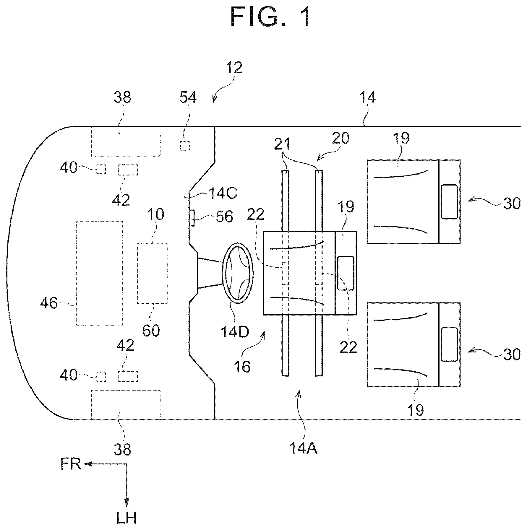
As shown in , a steering wheel 14 D is provided on an instrument panel 14 C of a vehicle body 14 of a vehicle 12 on which the vehicle control device 10 is mounted. Further, a front seat 16 is provided in a vehicle cabin 14 A. As shown in , an occupant P 1 is seated in the front seat 16 . The front seat 16 includes a seat 19 and a slide rail device 20 .
As shown in , a floor 14 B of the vehicle cabin 14 A is provided with the slide rail device 20 that supports the seat 19 of the front seat 16 such that the seat 19 can be slid in the right-left direction. The slide rail device 20 includes a pair of front and rear lower rails 21 fixed to the floor 14 B and extending in the right-left direction, and a pair of front and rear upper rails 22 . Each of the upper rails 22 is supported by each of the lower rails 21 such that the upper rails 22 are slidable in the right-left direction. The slide rail device 20 includes a first actuator 24 composed of an electric motor and a power transmission mechanism (not shown). When the first actuator 24 generates a driving force while rotating in a normal direction, this driving force is transmitted from the power transmission mechanism to the upper rails 22 , and causes the upper rails 22 to slide to the left with respect to the lower rails 21 . When the first actuator 24 generates a driving force while rotating in a reverse direction, this driving force is transmitted from the power transmission mechanism to the upper rails 22 , and causes the upper rails 22 to slide to the right with respect to the lower rails 21 .
The seat 19 is supported by the front and rear upper rails 22 . The seat 19 includes a seat cushion 19 A, a seat back 19 B and a headrest 19 C. The seat cushion 19 A is fixed to the upper ends of the front and rear upper rails 22 . The rear end of the seat cushion 19 A and the lower end of the seat back 19 B are rotatably connected via a reclining mechanism 26 . The reclining mechanism 26 is provided with a second actuator 28 . When the second actuator 28 generates a driving force while rotating in the normal direction, the reclining mechanism 26 rotates by this driving force, and the seat back 19 B rotates relative to the seat cushion 19 A forward. When the second actuator 28 generates a driving force while rotating in the reverse direction, the reclining mechanism 26 rotates by this driving force, and the seat back 19 B rotates relative to the seat cushion 19 A rearward.
As shown in , the headrest 19 C includes a cushion portion 19 C 1 and a pair of right and left stays 19 C 2 whose upper ends are fixed to the cushion portion 19 C 1 . The right and left stays 19 C 2 are slidably supported on the upper end of the seat back 19 B in the up-down direction.
The cushion portion 19 C 1 includes a base portion 19 C 3 serving as a rear portion thereof and a pair of side portions 19 C 4 . Each of the side portions 19 C 4 extends forward from each of right and left ends of the base portion 19 C 3 . That is, the planar shape of the cushion portion 19 C 1 is a U-shape. The outer shape of the cushion portion 19 C 1 is composed of an outer skin material 19 C 5 having flexibility. In the internal space of the outer skin material 19 C 5 , a bag body 19 C 6 having a U-shape in a plan view, a plurality of springs 19 C 7 , and a cushion material (not shown) are provided. The bag body 19 C 6 is composed of a flexible material. The inside of the bag body 19 C 6 is filled with a liquid (not shown). One end of each spring 19 C 7 is supported by the bag body 19 C 6 , and the other end of each spring 19 C 7 is supported by the inner peripheral surface of the outer skin material 19 C 5 .
As shown in , when the occupant P 1 is seated in the front seat 16 (seat 19 ), a waist P 1 a of the occupant P 1 is supported by the seat cushion 19 A, a back P 1 b of the occupant P 1 is supported by the seat back 19 B, and a head P 1 c of the occupant P 1 is supported by the cushion portion 19 C 1 . Further, as shown in , the rear portion and both side portions of the head P 1 c are surrounded by the cushion portion 19 C 1 . For example, as shown in , the rear portion of the head P 1 c is supported by the base portion 19 C 3 and both side portions of the head P 1 c are supported by the side portions 19 C 4 .
As shown in , the floor 14 B is provided with a pair of right and left rear seats 30 located rearward of the front seat 16 . Each rear seat 30 includes a seat 19 and a lifter mechanism 32 .
The lifter mechanism 32 provided on the floor 14 B includes a third actuator 34 composed of an electric motor. In , the lifter mechanism 32 is schematically shown. The lifter mechanism 32 has a configuration disclosed in, for example, Japanese Unexamined Patent Application Publication No. 2012-62020 (JP 2012-62020 A). The seat cushion 19 A of the seat 19 is supported on the upper end of the lifter mechanism 32 . When the third actuator 34 generates a driving force while rotating in the normal direction, the driving force causes the lifter mechanism 32 to extend in the up-down direction. When the third actuator 34 generates a driving force while rotating in the reverse direction, the driving force causes the lifter mechanism 32 to shorten in the up-down direction. When the lifter mechanism 32 extends and shortens in the up-down direction, the angle of the seat cushion 19 A in the side view with respect to the horizontal direction (front-rear direction) changes.
An occupant P 2 is seated in the rear seat 30 . When the occupant P 2 is seated in the rear seat 30 (seat 19 ), a waist P 2 a of the occupant P 2 is supported by the seat cushion 19 A, a back P 2 b of the occupant P 2 is supported by the seat back 19 B, and a head P 2 c of the occupant P 2 is supported by the cushion portion 19 C 1 . Further, the rear portion and both side portions of the head P 2 c are surrounded by the cushion portion 19 C 1 . For example, as shown in , the rear portion of the head P 2 c is supported by the base portion 19 C 3 and the both side portions of the head P 2 c are supported by the side portions 19 C 4 .
Although not shown, the vehicle 12 includes three seatbelt devices each corresponding to the front seat 16 and the rear seats 30 . The occupant P 1 seated in the front seat 16 and the occupant P 2 seated in each of the rear seat 30 wear corresponding seatbelt devices.
As shown in , in the vicinity of four wheels 38 provided on the vehicle 12 (only two front wheels are shown in ), a wheel speed sensor 40 that detects the wheel speed of each wheel 38 (only two wheel speed sensors are shown in ) is provided. Further, the vehicle 12 is provided with four brake devices 42 (only two brake devices are shown in ) capable of applying a braking force to each wheel 38 . Further, an engine 46 is provided at the front of the vehicle 12 .
As shown in , a camera 50 is provided on the rear surface of the front windshield 14 E provided on the vehicle body 14 . The camera 50 can take an image of a subject located in front of the front windshield 14 E.
Further, as shown in , a heart rate monitor 52 is provided inside the seat back 19 B of the seat 19 of each of the front seat 16 and the rear seats 30 . The heart rate monitor 52 in the front seat 16 measures the heart rate of the occupant P 1 seated in the front seat 16 . The heart rate monitor 52 in the rear seat 30 measures the heart rate of the occupant P 2 seated in the rear seat 30 .
Further, as shown in , the vehicle 12 is provided with a Global Positioning System (GPS) receiver 54 . The GPS receiver 54 acquires position information (latitude, longitude, etc.) of a point where the vehicle 12 is traveling based on a GPS signal transmitted from an artificial satellite at a predetermined cycle.
Further, the instrument panel 14 C is provided with an automatic driving switch 56 .
As shown in , the vehicle 12 is provided with an electronic control unit (ECU) 60 . The ECU 60 is electrically connected to the first actuator 24 , the second actuator 28 , the third actuator 34 , the wheel speed sensor 40 , the brake device 42 , the engine 46 , the camera 50 , the heart rate monitor 52 , the GPS receiver 54 , and the automatic driving switch 56 . The ECU 60 shown in is configured to include a central processing unit (CPU: processor) 60 A, a read-only memory (ROM) 60 B, a random access memory (RAM) 60 C, a storage 60 D, a communication interface (I/F) 60 E, and an input-output I/F 60 F. The CPU 60 A, the ROM 60 B, the RAM 60 C, the storage 60 D, the communication I/F 60 E, and the input-output I/F 60 F are connected so as to be able to communicate with each other via a bus 60 Z. The ECU 60 can acquire information of the date and time from a timer (not shown).
The CPU 60 A is a central processing unit that executes various programs and that controls various units. That is, the CPU 60 A reads the program from the ROM 60 B or the storage 60 D and executes the program using the RAM 60 C as a work area. The CPU 60 A controls each configuration and performs various arithmetic processes in accordance with the program recorded in the ROM 60 B or the storage 60 D.
The ROM 60 B stores various programs and various data. The RAM 60 C temporarily stores a program or data as a work area. The storage 60 D is composed of a storage device such as a hard disk drive (HDD) or a solid state drive (SSD), and stores various programs and various data. The communication I/F 60 E is an interface for the ECU 60 to communicate with other devices. The input-output I/F 60 F is an interface for communicating with various devices.
The vehicle 12 is equipped with a navigation system. Map data, which is part of the navigation system, is recorded in the storage 60 D of the ECU 60 . The GPS receiver 54 is also a part of the navigation system. The map data received by the vehicle 12 from the Web server using wireless communication via the Internet may be used as part of the navigation system.
As shown in , the ECU 60 includes a sleep depth estimation unit 601 , an external force prediction unit 602 , and an automatic driving control unit (control unit) 603 as functional configurations. The sleep depth estimation unit 601 , the external force prediction unit 602 , and the automatic driving control unit 603 are realized by the CPU 60 A reading and executing the program stored in the ROM 60 B or the storage 60 D.
When the ECU 60 acquires data on the heart rates of the occupants P 1 and P 2 acquired by the heart rate monitors 52 , the sleep depth estimation unit 601 estimates (detects) the sleep depths of the occupants P 1 and P 2 based on the data. The sleep depth estimation unit 601 according to the present embodiment estimates the sleep depth in five levels. That is, the sleep depth estimated by the sleep depth estimation unit 601 includes the sleep depths of levels 1 to 5. The sleep depth of level 1 is the depth corresponding to rapid eye movement (REM) sleep. Each of the sleep depths of levels 2 to 5 is the depth corresponding to non-rapid eye movement (Non-REM) sleep. Levels 2 and 3 correspond to the Non-REM sleep in stages 1 and 2, respectively. Levels 4 and 5 correspond to the Non-REM sleep (slow wave sleep) in stage 3 and 4, respectively.
The external force prediction unit 602 calculates (predicts) the magnitude and the direction of the external force to be applied to the occupants P 1 and P 2 within a predetermined time from the current time based on information acquired by the ECU 60 from the navigation system, the wheel speed sensor 40 , and the camera 50 . This predetermined time is, for example, 10 seconds. However, this predetermined time may be a time having a length different from 10 seconds.
For example, as shown in , a case is assumed in which an uneven portion 72 existing on a road surface 71 of a road 70 in which the vehicle 12 is traveling along a traveling direction A is included in image data transmitted from the camera 50 to the ECU 60 . In this case, the external force prediction unit 602 predicts an external force F 1 in the up-down direction to be applied to the vehicle 12 from the road surface 71 when the wheels 38 of the vehicle 12 that maintains the vehicle speed at the current time gets over the uneven portion 72 within the predetermined time from the current time, based on information including the vehicle speed at the current time calculated based on information related to the wheel speed transmitted from the wheel speed sensor 40 , the distance from the vehicle 12 to the uneven portion 72 calculated based on the image data, and the magnitude (height) of the uneven portion 72 . That is, the magnitude and the direction of the external force F 1 that causes the vehicle 12 to vibrate in the up-down direction are predicted.
Further, as shown in , a case is assumed in which a curved portion 76 that is a part of a road 75 in which the vehicle 12 is traveling straight along a traveling direction B is included in the image data transmitted from the camera 50 to the ECU 60 . In this case, the external force prediction unit 602 predicts, based on information including the vehicle speed at the current time and the radius of curvature of the curved portion 76 , the magnitude and the direction of a centrifugal force (external force) F 2 to be applied to the vehicle 12 (occupants P 1 and P 2 ) when the vehicle 12 that maintains the vehicle speed at the current time travels on the curved portion 76 within the predetermined time from the current time. The radius of curvature of the curved portion 76 can be calculated by the external force prediction unit 602 based on the image data. The external force prediction unit 602 can recognize the curved portion 76 on the road 75 and the radius of curvature of the curved portion 76 based on information acquired by the ECU 60 from the map information of the navigation system. That is, the external force prediction unit 602 can recognize the curved portion 76 on the road 75 and the radius of curvature of the curved portion 76 based on information from one of the camera 50 and the navigation system.
Further, as shown in , a case is assumed in which an inclined portion (slope) 82 that is a part of a road 80 is included in the image data captured by the camera 50 and transmitted to the ECU 60 when the vehicle 12 is traveling on a horizontal portion 81 of the road 80 along a traveling direction C. In this case, the external force prediction unit 602 predicts the magnitude and the direction of an external force F 3 to be applied to the vehicle 12 (occupants P 1 and P 2 ) when the vehicle 12 that maintains the vehicle speed at the current time moves from the horizontal portion 81 to the inclined portion 82 within the predetermined time from the current time based on information including the vehicle speed at the current time, an inclination angle (gradient) 01 of the inclined portion 82 , and an inclination direction of the inclined portion 82 . As shown by the arrow in , the external force F 3 is a force in a rotational direction along an extension direction (vehicle front-rear direction) of the road 80 . The inclination angle θ1 and the inclination direction of the inclined portion 82 can be estimated (calculated) by the external force prediction unit 602 from the image data. The external force prediction unit 602 can recognize, based on the information acquired by the ECU 60 from the map information of the navigation system, the inclined portion 82 on the road 80 in which the vehicle 12 is traveling, and the inclination angle θ1 and the inclination direction of the inclined portion 82 . That is, the external force prediction unit 602 can recognize the inclined portion 82 on the road 80 and the inclination angle θ1 and the inclination direction of the inclined portion 82 based on the information from one of the camera 50 and the navigation system.
The automatic driving control unit 603 functions when the automatic driving switch 56 located at the OFF position moves to the ON position. The automatic driving control unit 603 executes automatic driving control (driving support control) of the vehicle 12 by operating each device of the vehicle 12 including the brake device 42 , the engine 46 , and the steering device (not shown). The term “automatic driving” used in the present specification includes 1 to 5 levels of automatic driving defined by Society of Automotive Engineers (SAE).
Operation and Effects
Next, the operation and effects of the present embodiment will be described.
The ECU 60 of the vehicle control device 10 repeatedly executes the process of the flowchart of .
First, in step S 10 , the automatic driving control unit 603 of the ECU 60 determines whether the automatic driving control of level 5 is being executed. That is, the automatic driving control unit 603 determines whether the vehicle 12 is executing so-called fully automatic driving.
The ECU 60 that has determined Yes in step S 10 proceeds to step S 11 . In step S 11 , the external force prediction unit 602 of the ECU 60 determines whether the above external force is predicted to be applied to the vehicle 12 within the predetermined time from the current time. That is, the external force prediction unit 602 determines whether at least one of the external force F 1 , the external force F 2 , and the external force F 3 is applied to the vehicle 12 within the predetermined time from the current time, for example.
The ECU 60 that has determined Yes in step S 11 proceeds to step S 12 . In step S 12 , the sleep depth estimation unit 601 of the ECU 60 estimates the sleep depths of the occupants P 1 and P 2 based on the data related to the heart rates of the occupants P 1 and P 2 acquired from the heart rate monitor 52 . Further, the sleep depth estimation unit 601 determines whether the sleep depth of at least one of the occupant P 1 and the occupant P 2 is equal to or lower than a reference depth or at least one of the occupant P 1 and the occupant P 2 is awake. The reference depth according to the present embodiment is a sleep depth of level 3. Therefore, when the sleep depth of at least one of the occupant P 1 and the occupant P 2 is one of levels 1 to 3, or at least one of the occupant P 1 and the occupant P 2 is awake, the sleep depth estimation unit 601 determines Yes in step S 12 . On the other hand, when the sleep depths of all the occupants are level 4 or level 5, the sleep depth estimation unit 601 determines No in step S 12 .
The ECU 60 that has determined Yes in step S 12 proceeds to step S 13 . For example, when the sleep depths of the occupants P 1 and P 2 are level 3 or lower, the ECU 60 proceeds to step S 13 .
For example, when the vehicle 12 passes through the uneven portion 72 of , the automatic driving control unit 603 of the ECU 60 that has proceeded to step S 13 controls the brake device 42 such that the magnitude of the external force F 1 to be applied to the vehicle 12 is equal to or less than a predetermined first threshold value. That is, the automatic driving control unit 603 applies the braking force from the brake device 42 to each wheel 38 to reduce the vehicle speed of the vehicle 12 . Here, the first threshold value is a value obtained by multiplying a first coefficient that is “zero” or more and smaller than “one” by the magnitude of the external force F 1 when the vehicle 12 passes through the uneven portion 72 at the vehicle speed of the current time. The first coefficient is recorded in the ROM 60 B or the storage 60 D.
The magnitude of the external force F 1 in the up-down direction to be applied from the uneven portion 72 to the vehicle 12 (occupants P 1 and P 2 ) when the vehicle 12 passes through the uneven portion 72 increases as a vehicle speed when the vehicle 12 passes through the uneven portion 72 increases. Therefore, when the vehicle 12 passes through the uneven portion 72 at a speed equal to or lower than a predetermined vehicle speed, the external force F 1 to be applied to the vehicle 12 is equal to or less than the first threshold value. Therefore, when the vehicle 12 passes through the uneven portion 72 , there is little possibility that the occupants P 1 and P 2 in states of light sleeping will wake up. Further, a possibility that transition from the wake-up states of the occupants P 1 and P 2 to the sleeping states thereof is hindered by the vehicle 12 passing through the uneven portion 72 is reduced.
Further, when the ECU 60 performs the process of step S 13 , as shown in , the automatic driving control unit 603 may control the second actuator 28 (reclining mechanism 26 ) to reduce the angle θ2 between the up-down direction and an extension direction D of the seat back 19 B of the seat 19 of each of the front seat 16 and the rear seats 30 . As shown in , the external force F 1 to be applied to the vehicle 12 is transmitted as a force F 1 p from the base portion 19 C 3 of the seat 19 to the heads P 1 c and P 2 c of the occupants P 1 and P 2 . This force F 1 p is a value obtained by multiplying the external force F 1 by sin θ2. Therefore, the smaller the value of the angle θ2 becomes, the smaller the value of the force F 1 p becomes. The external force to be applied to the heads P 1 c and P 2 c of the occupants P 1 and P 2 has a greater influence on the sleeping states of the occupants P 1 and P 2 than the external force to be applied to the parts other than the heads P 1 c and P 2 c of the occupants P 1 and P 2 . Therefore, by reducing the angle θ2 between the up-down direction and the extension direction D of the seat back 19 B of the seat 19 of each of the front seat 16 and the rear seats 30 , when the vehicle 12 passes through the uneven portion 72 , the possibility that the occupants P 1 and P 2 in states of light sleeping will wake up can be reduced, and the possibility that the transition from the wake-up states of the occupants P 1 and P 2 to the sleeping states thereof is hindered can be reduced.
is a comparative example of . In this comparative example, when the ECU 60 performs the process of step S 13 , as shown in , the automatic driving control unit 603 controls the second actuator 28 (reclining mechanism 26 ) to increase the angle θ2. The angle θ2 in this case is about 90°. In this case, as shown in , the external force F 1 to be applied to the vehicle 12 is transmitted to the heads P 1 c and P 2 c of the occupants P 1 and P 2 as a force having almost the same magnitude as that of the external force F 1 . Therefore, in this case, when the vehicle 12 passes through the uneven portion 72 , the possibility that the occupants P 1 and P 2 in the states of light sleeping will wake up is higher than in the case of , and the possibility that the transition from the wake-up states of the occupants P 1 and P 2 to the sleeping states thereof is hindered is higher than in the case of .
Further, for example, when the vehicle 12 travels on the road 75 of , the automatic driving control unit 603 of the ECU 60 that has proceeded to step S 13 controls the brake device 42 such that the external force (centrifugal force) F 2 to be applied to the occupants P 1 and P 2 when the vehicle 12 travels on the curved portion 76 is equal to or less than the first threshold value. That is, the automatic driving control unit 603 applies the braking force from the brake device 42 to each wheel 38 to reduce the vehicle speed of the vehicle 12 . The first threshold value in this case is a value obtained by multiplying the first coefficient by the magnitude of the external force F 2 when the vehicle 12 passes through the curved portion 76 at the vehicle speed of the current time. The magnitude of the external force F 2 when the vehicle 12 travels on the curved portion 76 is proportional to the square of the vehicle speed. Therefore, by reducing the vehicle speed when the vehicle 12 travels on the curved portion 76 , the magnitude of the external force F 2 to be applied to the occupants P 1 and P 2 when the vehicle 12 travels on the curved portion 76 is equal to or less than the first threshold value. Therefore, when the vehicle 12 passes through the curved portion 76 , there is little possibility that the occupants P 1 and P 2 in states of light sleeping will wake up. Further, the possibility that the transition from the wake-up states of the occupants P 1 and P 2 to the sleeping states thereof is hindered by the vehicle 12 passing through the curved portion 76 is reduced.
Further, in step S 13 , the automatic driving control unit 603 controls the first actuator 24 . More specifically, when the vehicle 12 travels on the curved portion 76 , the first actuator 24 controlled by the automatic driving control unit 603 causes the upper rails 22 and the seat 19 of the front seat 16 to slide to the right side with respect to the lower rails 21 (width direction of the vehicle 12 ). Since a leftward inertial force IF (see ) to be generated in the seat 19 by the sliding of the seat 19 to the right side is a force in a direction opposite to the direction of the external force F 2 , this inertial force IF is cancelled out by a part of the external force F 2 . Therefore, when the seat 19 is moved to the right side, the external force F 2 to be applied to the occupant P 1 becomes smaller.
Further, for example, when the vehicle 12 travels on the road 80 of , the automatic driving control unit 603 of the ECU 60 that has proceeded to step S 13 controls the brake device 42 such that the external force F 3 to be applied to the occupants P 1 and P 2 is equal to or less than the first threshold value. That is, the automatic driving control unit 603 applies the braking force from the brake device 42 to each wheel 38 to reduce the vehicle speed of the vehicle 12 . The first threshold value in this case is a value obtained by multiplying the first coefficient by the magnitude of the external force F 3 when the vehicle 12 moves from the horizontal portion 81 to the inclined portion 82 at the vehicle speed of the current time. The magnitude of the external force F 3 when the vehicle 12 moves from the horizontal portion 81 to the inclined portion 82 increases as the vehicle speed increases. Therefore, by reducing the vehicle speed when the vehicle 12 moves from the horizontal portion 81 to the inclined portion 82 , the magnitude of the external force F 3 to be applied to the occupants P 1 and P 2 when the vehicle 12 moves from the horizontal portion 81 to the inclined portion 82 is equal to or less than the first threshold value. Therefore, when the vehicle 12 moves from the horizontal portion 81 to the inclined portion 82 , there is little possibility that the occupants P 1 and P 2 in states of light sleeping will wake up. Further, the possibility that the transition from the wake-up states of the occupants P 1 and P 2 to the sleeping states thereof is hindered by the vehicle 12 moving from the horizontal portion 81 to the inclined portion 82 is reduced.
Further, in step S 13 , the automatic driving control unit 603 may control the third actuator 34 . More specifically, when the vehicle 12 moves from the horizontal portion 81 to the inclined portion 82 , the third actuator 34 controlled by the automatic driving control unit 603 may drive the lifter mechanism 32 of the rear seat 30 to rotate the entire seat 19 rearward by the inclination angle θ1 along the same direction as the external force F 3 as shown in . The seat 19 shown by the solid line in shows the seat 19 of the vehicle 12 that has moved to the inclined portion 82 without operating the third actuator 34 . The seat 19 shown by the virtual line in shows the seat 19 of the vehicle 12 that has moved to the inclined portion 82 while operating the third actuator 34 . An inertial force DF to be generated in the seat 19 when the entire seat 19 is rotated in the same direction as the external force F 3 by the third actuator 34 as described above is a force in a direction opposite to the direction of the external force F 3 . Therefore, the inertial force DF to be generated in the seat 19 when the entire seat 19 is rotated in the same direction as the external force F 3 is cancelled out by a part of the external force F 3 . As a result, when the entire seat 19 is rotated in the same direction as the external force F 3 , the external force F 3 to be applied to the occupant P 2 becomes smaller.
The automatic driving control unit 603 may control the second actuator 28 instead of the third actuator 34 . More specifically, when the vehicle 12 moves from the horizontal portion 81 to the inclined portion 82 , the second actuator 28 controlled by the automatic driving control unit 603 may drive the reclining mechanism 26 of the rear seat 30 to rotate the seat back 19 B rearward by the inclination angle θ1 along the same direction as the external force F 3 as shown in . The seat back 19 B shown by the solid line in shows the seat back 19 B of the vehicle 12 that has moved to the inclined portion 82 without operating the reclining mechanism 26 . The seat back 19 B shown by the virtual line in shows the seat back 19 B of the vehicle 12 that has moved to the inclined portion 82 while operating the reclining mechanism 26 . The inertial force DF to be generated in the seat back 19 B (occupant P 2 ) when the seat back 19 B is rotated in the same direction as the external force F 3 by the reclining mechanism 26 as described above is cancelled out by a part of the external force F 3 . As a result, when the seat back 19 B is rotated in the same direction as the external force F 3 , the external force F 3 to be applied to the occupant P 2 becomes smaller.
As shown by the virtual line in , when the road 80 includes an inclined portion 83 whose inclination direction is opposite to that of the inclined portion 82 , in step S 13 , the automatic driving control unit 603 drives the lifter mechanism 32 and reclining mechanism 26 to rotate the seat back 19 B in a direction opposite to the direction described above.
The automatic driving control unit 603 of the ECU 60 that has ended the process of step S 13 proceeds to step S 14 and determines whether the external forces F 1 , F 2 , and F 3 have disappeared. That is, the automatic driving control unit 603 determines whether the vehicle 12 has passed through the uneven portion 72 or the curved portion 76 , or the vehicle 12 that has moved to the inclined portion 82 has traveled on the inclined portion 82 by a predetermined distance, based on the position information obtained from the navigation system or the image data received from the camera 50 .
The ECU 60 that has determined Yes in step S 14 proceeds to step S 17 , and ends the control executed by the automatic driving control unit 603 in step S 13 . That is, the automatic driving control unit 603 controls the engine 46 (at least one of the opening degree of a throttle valve and the injection amount of fuel) to return the vehicle speed of the vehicle 12 to the vehicle speed before the process of step S 13 is executed. Further, the automatic driving control unit 603 returns the upper rails 22 and the seat 19 (seat back 19 B) to the positions before the process of step S 13 is executed.
On the other hand, when the determination result is No in step S 14 , the ECU 60 returns to step S 13 . That is, the automatic driving control unit 603 continues the control executed in step S 13 .
On the other hand, when the determination result is No in step S 12 , the ECU 60 proceeds to step S 15 . That is, when the sleep depths of all the occupants P 1 and P 2 are level 4 or level 5, the ECU 60 proceeds to step S 15 .
The process performed by the ECU 60 in step S 15 is similar to the process performed by the ECU 60 in step S 13 . However, the automatic driving control unit 603 of the ECU 60 that has proceeded to step S 15 controls the brake device 42 such that the magnitude of the external force F 1 to be applied to the vehicle 12 when the vehicle 12 passes through the uneven portion 72 of , the magnitude of the external force F 2 when the vehicle 12 travels on the curved portion 76 of , and the magnitude of the external force F 3 when the vehicle 12 moves from the horizontal portion 81 to the inclined portion 82 of are equal to or less than a predetermined second threshold value. That is, the automatic driving control unit 603 applies the braking force from the brake device 42 to each wheel 38 to reduce the vehicle speed of the vehicle 12 . Here, the second threshold value of the external force F 1 is obtained by multiplying a second coefficient that is larger than “zero” and smaller than “one” by the magnitude of the external force F 1 when the vehicle 12 passes through the uneven portion 72 at the vehicle speed of the current time, and is larger than the first threshold value of the external force F 1 . Similarly, the second threshold value of the external force F 2 is a value obtained by multiplying the second coefficient by the magnitude of the external force F 2 when the vehicle 12 travels on the curved portion 76 at the vehicle speed of the current time, and is larger than the first threshold value of the external force F 2 . Similarly, the second threshold value of the external force F 3 is a value obtained by multiplying the second coefficient by the magnitude of the external force F 3 when the vehicle 12 moves from the horizontal portion 81 to the inclined portion 82 at the vehicle speed of the current time, and is larger than the first threshold value of the external force F 3 . That is, the second coefficient is larger than the first coefficient. The second coefficient is recorded in the ROM 60 B or the storage 60 D. Since the second coefficient is larger than the first coefficient, deceleration of the vehicle 12 in step S 15 is smaller than deceleration of the vehicle 12 in step S 13 .
The automatic driving control unit 603 of the ECU 60 that has ended the process of step S 15 proceeds to step S 16 and determines whether the external forces F 1 , F 2 , and F 3 have disappeared.
The ECU 60 that has determined Yes in step S 16 proceeds to step S 17 , and ends the control executed by the automatic driving control unit 603 in step S 15 .
On the other hand, when the determination result is No in step S 16 , the ECU 60 returns to step S 15 . That is, the automatic driving control unit 603 continues the control executed in step S 15 .
When the ECU 60 ends the process of step S 17 , or the determination result is NO in steps S 10 and S 11 , the ECU 60 temporarily ends the process of the flowchart of .
In the vehicle control device 10 according to the present embodiment described above, the automatic driving control unit 603 of the ECU 60 controls the vehicle 12 such that the external forces F 1 , F 2 , and F 3 are equal to or less than the predetermined threshold value while considering the external forces F 1 , F 2 , and F 3 that are predicted to be applied to the occupants P 1 and P 2 within the predetermined time. That is, the vehicle control device 10 does not control the vehicle 12 based on the magnitudes of the external forces F 1 , F 2 , and F 3 that are actually generated. Therefore, the vehicle control device 10 can suppress the large external forces F 1 , F 2 , and F 3 from being applied to the occupants P 1 and P 2 due to the behavior of the vehicle 12 .
Further, when the sleep depth of at least one of the occupant P 1 and the occupant P 2 is equal to or lower than the reference depth or at least one of the occupant P 1 and the occupant P 2 is in the wake-up state, the automatic driving control unit 603 controls the vehicle 12 such that the magnitudes of the external forces F 1 , F 2 and F 3 to be applied to the occupants P 1 and P 2 are equal to or less than the first threshold value. On the other hand, when the sleep depths of all the occupants P 1 and P 2 are greater than the reference depth, the automatic driving control unit 603 controls the vehicle 12 such that the magnitudes of the external forces F 1 , F 2 , and F 3 to be applied to the occupants P 1 and P 2 are equal to or less than the second threshold value larger than the first threshold value. That is, the ECU 60 of the vehicle control device 10 controls the vehicle 12 while considering the sleep depths of the occupants P 1 and P 2 . Further, the second threshold value that is a threshold value to be adopted when the sleep depths of the occupants P 1 and P 2 are greater than the reference depth is larger than the first threshold value that is a threshold value to be adopted when the sleep depths of the occupants P 1 and P 2 are equal to or lower than the reference depth or the occupants P 1 and P 2 are in the wake-up states. That is, the vehicle speed to be allowed when the sleep depths of the occupants P 1 and P 2 are great is higher than the vehicle speed to be allowed when the sleep depths are low. Therefore, when the sleep depths of the occupants P 1 and P 2 are great, the vehicle 12 can travel at a higher vehicle speed than when the sleep depths are low.
Therefore, the vehicle control device 10 according to the present embodiment can suppress the large external forces F 1 , F 2 , and F 3 from being applied to the occupants P 1 and P 2 due to the behavior of the vehicle 12 while considering the sleep depths of the occupants P 1 and P 2 seated on the seat 19 .
Further, the headrest 19 C of each seat 19 includes the base portion 19 C 3 and the pair of side portions 19 C 4 . As shown in , the rear surface of each of the heads P 1 c and P 2 c is supported by the base portion 19 C 3 and the both side surfaces of each of the heads P 1 c and P 2 c are supported by the side portions 19 C 4 . Therefore, forces due to the external forces F 1 , F 2 , and F 3 are dispersed more widely to be transmitted from the headrest 19 C to the heads P 1 c and P 2 c than when the headrest 19 C does not include the side portions 19 C 4 . Therefore, when the forces due to the external forces F 1 , F 2 , and F 3 are applied to the heads P 1 c and P 2 c , an influence of the forces on the sleeping states of the occupants P 1 and P 2 can be reduced as compared with a case where the headrest 19 C does not include the side portions 19 C 4 .
Further, the headrest 19 C includes the bag body 19 C 6 filled with a liquid and the springs 19 C 7 . This bag body 19 C 6 functions as a damper. Further, when the forces due to the external forces F 1 , F 2 , and F 3 are applied from the headrest 19 C to the heads P 1 c and P 2 c , the springs 19 C 7 are elastically deformed. Therefore, when the forces due to the external forces F 1 , F 2 , and F 3 are applied to the heads P 1 c and P 2 c , an influence of the external forces F 1 , F 2 , and F 3 on the sleeping states of the occupants P 1 and P 2 can be reduced as compared with a case where the headrest 19 C does not include the bag body 19 C 6 and the springs 19 C 7 .
Further, in the vehicle control device 10 , when the sleep depth of the occupant P 1 is equal to or lower than the reference depth or when the occupant P 1 is in the wake-up state, the automatic driving control unit 603 of the ECU 60 uses the slide rail device 20 and the first actuator 24 to move the front seat 16 in the same direction as the external force F 2 and suppress the large external force F 2 from being applied to the occupant P 1 .
Further, when the external force prediction unit 602 predicts that the external force F 3 due to the inclination angle θ1 of the road 80 will be applied to the occupant P 2 in the vehicle 12 within the predetermined time from the current time, the vehicle control device 10 rotates the seat 19 (or seat back 19 B) in the same direction as a direction of the external force F 3 due to the inclination angle θ1. Therefore, when the vehicle 12 moves from the horizontal portion 81 of the road 80 to the inclined portion 82 of the road 80 , it is possible to suppress the large external force due to the inclination angle θ1 from be applied to the occupant P 2 .
Further, the automatic driving control unit 603 executes these controls for moving the seat 19 in the same direction as the external forces F 2 and F 3 only when the sleep depths of the occupants P 1 and P 2 are equal to or lower than the reference depth or the occupants P 1 and P 2 are in the wake-up states. Therefore, energy consumption required for controlling the vehicle 12 can be suppressed as compared with a case where these controls are executed even when the sleep depth is greater than the reference depth.
Although the vehicle control device 10 according to the embodiment has been described above, the design of the vehicle control device 10 can be appropriately changed without departing from the scope of the present disclosure.
For example, when the sleep depth is greater than the reference depth, the automatic driving control unit 603 may increase the angle between the seat cushion 19 A and the seat back 19 B as compared with a case where the sleep depth is equal to or lower than the reference depth, by controlling the reclining mechanism 26 (first actuator 24 ) to rotate the seat back 19 B rearward. With this configuration, the occupants P 1 and P 2 in states of deep sleeping can easily maintain the states of deep sleeping.
Further, various types and magnitudes of an external force applied to a vehicle having the same specifications as the vehicle 12 (not shown) when the vehicle travels on various roads may be stored in an external server with which the vehicle 12 can communicate, together with position information indicating a location where the external force is generated and a vehicle speed when the external force is generated. In this case, when the vehicle 12 accesses the external server, the external force prediction unit 602 of the ECU 60 can determine whether the external force is applied to the vehicle 12 within a predetermined time from the current time. Further, the external force prediction unit 602 can recognize the maximum value of the vehicle speed for setting the magnitude of the external force predicted to be applied to the vehicle 12 within the predetermined time from the current time to a value equal to or less than a predetermined value (for example, the first threshold value and the second threshold value) more accurately than the above embodiment. Therefore, in the vehicle 12 according to the modification, the magnitude of the external force can be set to the value equal to or less than the predetermined value while the vehicle speed is increased as compared with the above embodiment.
The slide rail device 20 may be omitted from the front seat 16 . Further, the lifter mechanism 32 may be provided on the front seat 16 .
The lifter mechanism 32 may be omitted from the rear seat 30 . Further, the slide rail device 20 may be provided on the rear seat 30 .
The heart rate monitor 52 may be omitted from the seat 19 , and the occupants P 1 and P 2 may wear a wearable device capable of measuring the heart rates of the occupants P 1 and P 2 and wirelessly transmitting the acquired heart rate data to the ECU 60 .
Further, the heart rate monitor 52 may be omitted from the seat 19 , and the vehicle 12 may be provided with an in-vehicle camera capable of capturing the faces of the occupants P 1 and P 2 . Image data captured by the in-vehicle camera is sent to the ECU 60 and analyzed by the sleep depth estimation unit 601 . The sleep depth estimation unit 601 determines the sleep depth based on the states of the eyes, etc. of the occupants P 1 and P 2 included in the image data. For example, the sleep depth estimation unit 601 measures the degree to which the eyelids of the occupants P 1 and P 2 are open and the cycle of opening and closing the eyelids from the images of surrounding portions of the eyes of the occupants P 1 and P 2 . Further, the automatic driving control unit 603 estimates the sleep depths of the occupants P 1 and P 2 based on the measured degree to which the eyelids of the occupants P 1 and P 2 are open and the measured cycle of opening and closing the eyelids.
In step S 15 , similarly to step S 13 , the ECU 60 may control at least one of the first actuator 24 , the second actuator 28 , and the third actuator 34 .
When the automatic driving level is one of levels 1 to 4 or when the automatic driving switch 56 is in the OFF position, the ECU 60 may execute the process of the flowchart of (excluding step S 10 ).
The present disclosure may be applied to a vehicle in which automatic driving control cannot be performed.
When the external force prediction unit 602 predicts that the external forces F 1 , F 2 , and F 3 having magnitudes equal to or larger than the predetermined value will not be applied within a predetermined time from the current time, and the sleep depth estimation unit 601 determines that the sleep depths of all the occupants P 1 and P 2 are greater than the reference depth, as shown in , the automatic driving control unit 603 may control the second actuator 28 (reclining mechanism 26 ) to set the angle θ2 to about 90°. That is, the angle θ2 may be increased as compared with a case where the sleep depth is equal to or lower than the reference depth. With this configuration, the occupant in a state of deep sleeping can easily maintain the state of deep sleeping.
Further, the seat 19 may include a device for adjusting the amount of liquid in the bag body 19 C 6 based on at least one of the sleep depth of the occupant and the magnitudes of the external forces F 1 , F 2 , and F 3 . This device adjusts the amount of liquid such that the bag body 19 C 6 exerts an appropriate damper effect according to the sleep depth of the occupant and the magnitudes of the external forces F 1 , F 2 , and F 3 . When the present disclosure is carried out according to the embodiment in the modification, an influence of the external forces F 1 , F 2 and F 3 on the sleeping states of the occupants P 1 and P 2 becomes smaller.
Figures (10)
Citations
This patent cites (25)
- US11351892
- US20050146186
- US20090108649
- US20130161989
- US20160176409
- US20180334062
- US20190061761
- US20200101936
- US20200307647
- US20200309549
- US20210114553
- US20230166638
- US20230339368
- US203876602
- US2003-063290
- US2005-199993
- US2006-175144
- US2006-224808
- US2007-022263
- US2007-261327
- US201262020
- US2018-177188
- US201938356
- US2020-055347
- US2020-165692