Power Supply Device and Power Supply System
Abstract
A power supply device includes: a power transmission coil unit; and a display unit displaying a mark indicating a power supply position of the movable object. A power transmission coil region of the power transmission coil unit has a point-symmetric shape with respect to a center of the power transmission coil region. The display unit includes a first display device displaying a first mark indicating a first power supply position of the movable object in a power supply space when the movable object enters the power supply space in a first direction, and a second display device displaying a second mark indicating a second power supply position of the movable object in the power supply space when the movable object enters the power supply space in a second direction opposite to the first direction.
Claims (8)
1. A power supply device comprising: a power transmission coil unit installed in a power supply space and capable of wirelessly transmitting electric power with respect to a power receiving coil unit mounted on a movable object existing in the power supply space, the movable object being capable of entering the power supply space; and a display unit installed around the power transmission coil unit and displaying a mark indicating a power supply position of the movable object when the power transmission coil unit transmits power to the power receiving coil unit, wherein when viewed from a normal direction of an installation surface of the power supply space on which the power transmission coil unit is installed, a power transmission coil region in which a power transmission coil is provided in the power transmission coil unit has a point-symmetric shape with respect to a center of the power transmission coil region, and wherein the display unit includes a first display device displaying a first mark indicating a first power supply position of the movable object in the power supply space when the movable object enters the power supply space in a first direction along an in-plane direction of the installation surface, and a second display device displaying a second mark indicating a second power supply position of the movable object in the power supply space when the movable object enters the power supply space in a second direction opposite to the first direction.
Show 7 dependent claims
2. The power supply device according to claim 1 , wherein the second display device is installed in a position different from that of the first display device.
3. The power supply device according to claim 1 , wherein the second display device displays the second mark in a color different from that of the first mark.
4. The power supply device according to claim 1 , further comprising a display controller controlling the display unit, wherein the display controller performs first control of allowing the first display device to display the first mark and the second display device to hide the second mark when the movable object enters the power supply space in the first direction, and performs second control of allowing the second display device to display the second mark and the first display device to hide the first mark when the movable object enters the power supply space in the second direction.
5. The power supply device according to claim 4 , further comprising an information processor receiving an entrance request including entrance direction information indicating an entrance direction of the movable object with respect to the power supply space from the movable object, wherein the display controller performs the first control when the entrance direction information indicates the first direction, and performs the second control when the entrance direction information indicates the second direction.
6. The power supply device according to claim 1 , wherein the movable object is a vehicle capable of traveling on a traveling road, the traveling road extends in a direction along the first direction and the second direction as an extending direction, and the power supply space is provided in a position adjacent to the traveling road in a direction intersecting the extending direction.
7. A power supply system, comprising: the power supply device according to claim 1 ; and the power receiving coil unit mounted on the movable object.
8. The power supply system according to claim 7 , wherein when viewed from the normal direction, a power receiving coil region in which a power receiving coil is provided in the power receiving coil unit has a point-symmetric shape with respect to a center of the power receiving coil region.
Full Description
Show full text →
TECHNICAL FIELD
The present disclosure relates to a power supply device and a power supply system.
BACKGROUND ART
Patent Literature 1 discloses a technology relevant to a power supply device. As disclosed in Patent Literature 1, the power supply device, for example, is installed in a power supply space (parking space) that is provided in a parking lot or the like. The power supply device is used to charge a battery of a vehicle that is parked in the power supply space. The transmission of electric power to the vehicle from the power supply device is attained between a power transmission coil provided in a power supply facility and a power receiving coil provided in the vehicle.
CITATION LIST
Patent Literature
Patent Literature 1: Japanese Unexamined Patent Publication No. 2019-096102
SUMMARY OF INVENTION
Technical Problem
The power supply device described above is configured by assuming a case where the vehicle enters the power supply space from one direction. Accordingly, in order for the vehicle to perform power supplying in the power supply space, it is required to adjust an entrance direction of the vehicle when entering the power supply space to the one direction. For this reason, for example, in a case where the vehicle travels in a direction opposite to the one direction, an operation of changing a travel direction of the vehicle is required. In a case where there is no space for performing the operation of changing the travel direction of the vehicle around the power supply space, it is necessary for the vehicle to give up the power supply in the power supply space and to search for another power supply space. As described above, in the power supply device described above, since extra operations and time may be required until the vehicle performs power supplying in the power supply space, there is room for improvement in convenience.
The present disclosure describes a power supply device and a power supply system that are capable of improving convenience in power supply.
Solution to Problem
A power supply device according to one aspect of the present disclosure, includes: a power transmission coil unit installed in a power supply space and capable of wirelessly transmitting electric power with respect to a power receiving coil unit mounted on a movable object existing in the power supply space, the movable object being capable of entering the power supply space; and a display unit installed around the power transmission coil unit and displaying a mark indicating a power supply position of the movable object when the power transmission coil unit transmits power to the power receiving coil unit. When viewed from a normal direction of an installation surface of the power supply space on which the power transmission coil unit is installed, a power transmission coil region in which a power transmission coil is provided in the power transmission coil unit has a point-symmetric shape with respect to a center of the power transmission coil region. The display unit includes a first display device displaying a first mark indicating a first power supply position of the movable object in the power supply space when the movable object enters the power supply space in a first direction along an in-plane direction of the installation surface, and a second display device displaying a second mark indicating a second power supply position of the movable object in the power supply space when the movable object enters the power supply space in a second direction opposite to the first direction.
Advantageous Effects of Invention
The present disclosure describes a power supply device and a power supply system that are capable of improving convenience in power supply.
BRIEF DESCRIPTION OF DRAWINGS
is a plan view illustrating a power supply facility in which a ground-side power transmitter according to one embodiment is installed.
A is an enlarged plan view illustrating a power transmission coil unit of the ground-side power transmitter in , and B is an enlarged plan view illustrating a power receiving coil unit of a vehicle-side power receiver in .
A is a plan view illustrating a state when a vehicle enters a power supply space in a first direction, and B is a plan view illustrating a state when the vehicle enters the power supply space in a second direction.
A is a plan view illustrating a state when the vehicle that enters the power supply space in the first direction reaches a first power supply position, and B is a plan view illustrating a state when the vehicle that enters the power supply space in the second direction reaches a second power supply position.
is a block diagram illustrating a functional configuration of the ground-side power transmitter and the vehicle-side power receiver.
is a flowchart illustrating a control flow of a ground-side controller from when the vehicle starts to enter the power supply space to when charging is completed in the power supply position.
is a flowchart illustrating a control flow of a vehicle-side controller from when the vehicle starts to enter the power supply space to when charging is completed in the power supply position.
is a diagram for describing an effect of the ground-side power transmitter.
is a plan view illustrating a modification example of a display unit of the ground-side power transmitter.
A is a plan view illustrating a state when the vehicle enters the power supply space in which the ground-side power transmitter illustrated in is installed in the first direction, and
B is a plan view illustrating a state when the vehicle enters the power supply space in which the ground-side power transmitter illustrated in is installed in the second direction.
is a plan view illustrating another modification example of the display unit of the ground-side power transmitter.
A is a plan view illustrating a state when the vehicle enters the power supply space in which the ground-side power transmitter illustrated in is installed in the first direction, and B is a plan view illustrating a state when the vehicle enters the power supply space in which the ground-side power transmitter illustrated in is installed in the second direction.
is a plan view illustrating a modification example of an installation site of the power supply space.
is a plan view illustrating another modification example of the installation site of the power supply space.
A is a plan view illustrating a modification example of the power transmission coil unit, and B is a plan view illustrating another modification example of the power transmission coil unit.
A, 16 B, 16 C, and 16 D are plan views illustrating modification examples of the shape of a power transmission coil region.
A is a plan view illustrating a state when the vehicle enters the power supply space in which a ground-side power transmitter according to a comparative example is installed in the first direction, and B is a plan view illustrating a state when the vehicle enters the power supply space in which the ground-side power transmitter according to the comparative example is installed in the second direction.
DESCRIPTION OF EMBODIMENTS
A power supply device according to one aspect of the present disclosure, includes: a power transmission coil unit installed in a power supply space and capable of wirelessly transmitting electric power with respect to a power receiving coil unit mounted on a movable object existing in the power supply space, the movable object being capable of entering the power supply space; and a display unit installed around the power transmission coil unit and displaying a mark indicating a power supply position of the movable object when the power transmission coil unit transmits power to the power receiving coil unit. When viewed from a normal direction of an installation surface of the power supply space on which the power transmission coil unit is installed, a power transmission coil region in which a power transmission coil is provided in the power transmission coil unit has a point-symmetric shape with respect to a center of the power transmission coil region. The display unit includes a first display device displaying a first mark indicating a first power supply position of the movable object in the power supply space when the movable object enters the power supply space in a first direction along an in-plane direction of the installation surface, and a second display device displaying a second mark indicating a second power supply position of the movable object in the power supply space when the movable object enters the power supply space in a second direction opposite to the first direction.
In the power supply device described above, the power transmission coil region has the point-symmetric shape when viewed from the normal direction. Accordingly, the shape of the power transmission coil region when viewed from the power receiving coil unit of the movable object is not changed between a case where the movable object enters the power supply space in the first direction and a case where the movable object enters the power supply space in the second direction. For this reason, insofar as the power receiving coil unit can be arranged such that one of the power receiving coil unit and the power transmission coil region falls inside the other when viewed from the normal direction in a case of power supply of the movable object that enters the power supply space in the first direction, the power receiving coil unit can similarly be arranged such that one of the power receiving coil unit and the power transmission coil region falls inside the other in a case of power supply of the movable object that enters the power supply space in the second direction. Accordingly, it is possible to allow magnetic flux generated from the power transmission coil region to efficiently reach the power receiving coil unit, and to avoid a situation in which transmission performance of power between the power receiving coil unit and the power transmission coil unit is degraded. As a result thereof, even in a case where an entrance direction of the movable object is the first direction or the second direction, desired transmission performance can be obtained. Further, in a case where the entrance direction of the movable object is the first direction, the movable object is capable of easily reaching the first power supply position by aiming for the first mark that is displayed on the first display device. In a case where the entrance direction of the movable object is the second direction, the movable object is capable of easily reaching the second power supply position by aiming for the second mark that is displayed on the second display device. As described above, in the power supply device described above, the movable object enters the power supply space from either of the both directions, and the power supplying can be performed in the power supply position with desired transmission performance. As a result thereof, since it is not necessary to perform extra operations of changing a movement direction of the movable object when performing the power supplying, it is possible to improve convenience in power supply.
In some aspects, the second display device may be installed in a position different from that of the first display device. In accordance with a mounting position of the power receiving coil unit in the movable object, the power supply positions at which the movable object needs to stop may be different from each other between a case where the entrance direction of the movable object is the first direction and a case where the entrance direction of the movable object is the second direction. In such a case, even when the entrance direction of the movable object is the first direction or the second direction, by installing the first display device and the second display device in positions different from each other, in accordance with each of the power supply positions, the movable object is capable of easily reaching the power supply position by aiming for the first mark or the second mark displayed on the positions different from each other.
In some aspects, the second display device may display the second mark in a color different from that of the first mark. In such a case, even when the entrance direction of the movable object is the first direction or the second direction, the movable object is capable of easily reaching the power supply position by aiming for the first mark or the second mark displayed in colors different from each other.
In some aspects, the power supply device may further include a display controller controlling the display unit. In a case where the movable object enters the power supply space in the first direction, the display controller may perform first control of allowing the first display device to display the first mark and the second display device to hide the second mark. In a case where the movable object enters the power supply space in the second direction, the display controller may perform second control of allowing the second display device to display the second mark and the first display device to hide the first mark. In such a configuration, in a case where the entrance direction of the movable object is the first direction, only the first mark is displayed. On the other hand, in a case where the entrance direction of the movable object is the second direction, only the second mark is displayed. As described above, by setting the first mark and the second mark not to be simultaneously displayed when the movable object enters the power supply space, it is possible to avoid a situation in which the movable object may mistakenly recognize the target mark to aim for, and to avoid a situation in which the movable object reaches a wrong power supply position. Therefore, according to the configuration described above, even in a case where the entrance direction of the movable object is the first direction or the second direction, the movable object is capable of more reliably reaching the power supply position.
In some aspects, the power supply device may further include an information processor receiving an entrance request including entrance direction information indicating an entrance direction of the movable object with respect to the power supply space from the movable object. The display controller may perform the first control when the entrance direction information indicates the first direction, and may perform the second control when the entrance direction information indicates the second direction. In such a configuration, the display controller is capable of performing display control of the first display device and the second display device at a timing when the information processor receives the entrance request from the movable object. Accordingly, the display controller is capable of displaying the first mark or the second mark, in accordance with the entrance direction of the movable object, at a suitable timing when the movable object enters the power supply space. As a result thereof, the movable object is capable of smoothly reaching the power supply position by aiming for the displayed first mark or the displayed second mark.
In some aspects, the movable object may be a vehicle capable of traveling on a traveling road. The traveling road may extend in a direction along the first direction and the second direction as an extending direction. The power supply space may be provided in a position adjacent to the traveling road in a direction intersecting the extending direction. As described above, when the power supply space is provided on the side of the traveling road, and a vehicle traveling on the traveling road in the first direction or the second direction stops by at the power supply space in order for power supply, it is assumed that the vehicle enters the power supply space from either of the first direction and the second direction. In a case where the entrance direction of the movable object with respect to the power supply space is set to only one direction, and the movable object travels in an opposite direction, extra operations of changing a travel direction of the movable object are required. In contrast, in the power supply device described above, as described above, since the vehicle is capable of entering the power supply space from either of the both directions, extra operations of changing the travel direction of the vehicle are not required, and the vehicle is capable of entering the power supply space and performing power supplying with desired transmission performance. Accordingly, in the configuration described above, the above effect of enabling the convenience in power supply to be improved can be preferably obtained.
A power supply system according to one aspect of the present disclosure, includes: the power supply device described above; and the power receiving coil unit mounted on the movable object. Since the power supply system includes the power supply device described above, and by using such a power supply system, the movable object is capable of entering the power supply space from either of the both directions and performing power supplying in the power supply position with desired transmission performance, as described above, the convenience in power supply can be improved.
In some aspects, when viewed from the normal direction, a power receiving coil region in which a power receiving coil is provided in the power receiving coil unit may have a point-symmetric shape with respect to a center of the power receiving coil region. As described above, since the power receiving coil region also has the point-symmetric shape when viewed from the normal direction, in addition to the power transmission coil region, in power supply, the aspect of allowing the magnetic flux generated from the power transmission coil region to efficiently reach the power receiving coil region can be more reliably attained. As a result thereof, it is possible to more reliably avoid a situation in which the transmission performance of the power between the power receiving coil unit and the power transmission coil unit is degraded.
Hereinafter, modes for implementing the present disclosure will be described in detail with reference to the attached drawings. In the description of the drawings, the same reference numerals will be applied to the same constituents, and the repeated description will be suitably omitted.
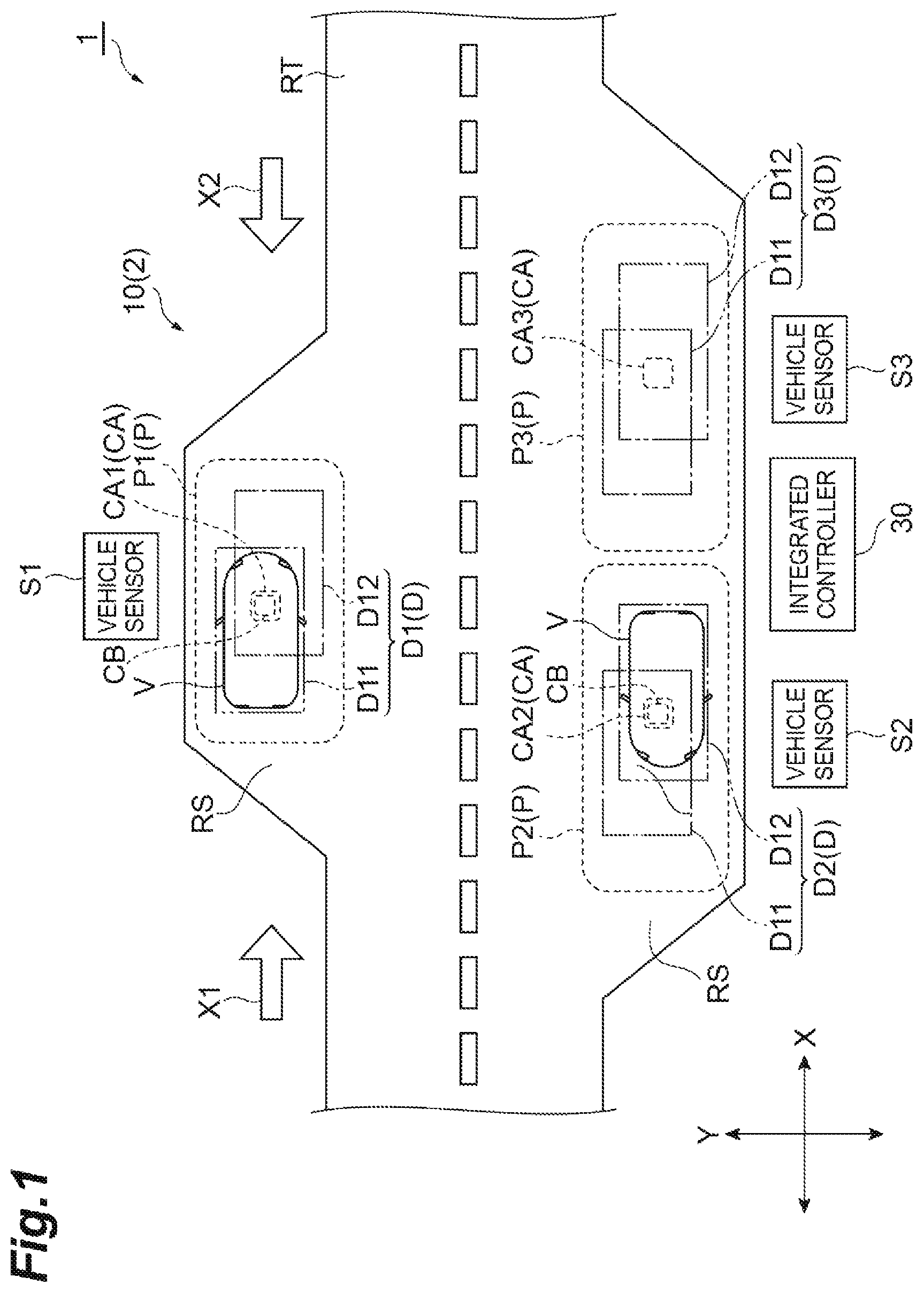
A power supply facility 1 illustrated in is a facility for supplying electric power to one or more movable objects. The movable object, for example, is a vehicle on which an electric device that requires power supply is mounted. The electric device, for example, is a battery that requires power supply for charging, an air-conditioning device that requires power supply for driving, or the like. Examples of such a vehicle include an electric automobile or a hybrid automobile on which a battery is mounted. In the present embodiment, an electric automobile will be described as an example of the movable object, and the movable object will be referred to as a “vehicle V”.
In the following description, in an in-plane direction of a road surface RS in the power supply facility 1 on which the vehicle V travels and stops, a direction in which the vehicle V moves before the start of power supply and after the end of power supply will be referred to as a front-back direction X, and a direction at a right angle with respect to the front-back direction X will be referred to as a left-right direction Y. In the front-back direction X, a direction from one side toward the other side will be referred to as a first direction X 1 , and a direction opposite to the first direction X 1 will be referred to as a second direction X 2 . In a direction which is a normal direction of the road surface RS and is perpendicular to the front-back direction X and the left-right direction Y, a direction from the road surface RS toward the vehicle V will be referred to as the top, and the opposite side thereof will be referred to as the bottom.
The power supply facility 1 includes a plurality of (three in the present embodiment) power supply spaces in which power supplying is performed to the vehicle V. In the following description, in a case where it is necessary to discriminate three power supply spaces from each other, reference numerals P 1 , P 2 , and P 3 will be applied to the power supply spaces. In a case where it is not necessary to discriminate three power supply spaces from each other, a reference numeral P will be simply applied to the power supply space. The power supply space P, for example, is a space at which one vehicle V is capable of stopping, and is a space extending in the front-back direction X on the road surface RS. Accordingly, the power supply space P has capaciousness in which at least one vehicle V is capable of stopping. That is, the length of the power supply space P in the front-back direction X is at least greater than the length of the vehicle V in the front-back direction X. The width of the power supply space P in the left-right direction Y is at least greater than the width of the vehicle V in the left-right direction Y.
The power supply space P, for example, is provided on the side of a traveling road RT extending in the front-back direction X. That is, the power supply space P is provided on the road surface RS adjacent to the traveling road RT in the left-right direction Y. In the present embodiment, the power supply space P is provided on the road surface RS on both sides of the traveling road RT in the left-right direction Y. More specifically, as illustrated in , one power supply space P 1 is arranged on the road surface RS on one side of the traveling road RT in the left-right direction Y. Then, two power supply spaces P 2 and P 3 are arranged on the road surface RS on the other side of the traveling road RT in the left-right direction Y. The power supply spaces P 2 and P 3 are arranged in parallel in the front-back direction X. The traveling road RT, for example, is a two-traffic lane road including a traffic lane in which the first direction X 1 is set as a travel direction of the vehicle V, and a traffic lane in which the second direction X 2 is set as the travel direction of the vehicle V. The traveling road RT may be a left-hand traffic road, or may be a right-hand traffic road.
In the power supply facility 1 , a ground-side power transmitter 10 (power supply device) is installed. In a case where the vehicle V traveling on the traveling road RT in the front-back direction X requires power supply, the vehicle V enters the power supply space P from the traveling road RT in the first direction X 1 or the second direction X 2 . The ground-side power transmitter 10 performs power supplying the vehicle V that enters the power supply space P. The number of vehicles V that are capable of stopping at the power supply facility 1 is identical to the number of power supply spaces P. In an example illustrated in , since the number of power supply spaces P is 3 , a maximum of three vehicles V are capable of stopping at the power supply facility 1 . The number of vehicles V that are capable of stopping at the power supply facility 1 can be suitably changed by increasing and decreasing the number of power supply spaces P, in accordance with a specification to be required for the power supply facility 1 .
The ground-side power transmitter 10 is capable of supplying power to a plurality of vehicles V that stop at the power supply facility 1 . In the example illustrated in , the ground-side power transmitter 10 is capable of supplying power to a maximum of three vehicles V that are capable of stopping at the power supply facility 1 . The ground-side power transmitter 10 is also capable of supplying power to one vehicle V, and is also capable of simultaneously supplying power to the plurality of vehicles V. Timings for supplying power to the plurality of vehicles V by the ground-side power transmitter 10 are independent from each other. Accordingly, a timing for supplying power to a certain vehicle V can be determined without being affected by a timing for supplying power to another vehicle V.
The ground-side power transmitter 10 configures a power supply system 2 together with a vehicle-side power receiver 20 mounted on the vehicle V. The power supply system 2 wirelessly supplies power to the vehicle-side power receiver 20 of the vehicle V that stops at the power supply space P from the ground-side power transmitter 10 by using magnetic coupling between the ground-side power transmitter 10 and the vehicle-side power receiver 20 . A power supply method of the power supply system 2 , for example, is magnetic resonance or electromagnetic induction.
The ground-side power transmitter 10 includes a plurality of (three in the present embodiment) power transmission coil units, a plurality of (three in the present embodiment) display units, and a plurality of (three in the present embodiment) vehicle sensors. Further, the ground-side power transmitter 10 includes an integrated controller 30 controlling the plurality of power transmission coil units and the plurality of display units. In the following description, in a case where it is necessary to discriminate the plurality of power transmission coil units from each other, reference numerals of CA 1 , CA 2 , and CA 3 will be applied to the power transmission coil units. In a case where it is not necessary to discriminate the plurality of power transmission coil units from each other, a reference numeral CA will be applied to the power transmission coil unit. Similarly, in a case where it is necessary to discriminate the plurality of display units from each other, reference numerals D 1 , D 2 , and D 3 will be applied to the display units. In a case where it is not necessary to discriminate the plurality of display units from each other, a reference numeral D will be applied to the display unit. Similarly, in a case where it is necessary to discriminate the plurality of vehicle sensors from each other, reference numerals S 1 , S 2 , and S 3 will be applied to the vehicle sensors. In a case where it is not necessary to discriminate the plurality of vehicle sensors from each other, a reference numeral S will be applied to the vehicle sensor.
The power transmission coil unit CA, the display unit D, and the vehicle sensor S are provided corresponding to each of the power supply spaces P. That is, for one power supply space P, one power transmission coil unit CA, one display unit D, and one vehicle sensor S are provided. For the power supply space P 1 , the power transmission coil unit CA 1 , the display unit D 1 , and the vehicle sensor S 1 are provided. For the power supply space P 2 , the power transmission coil unit CA 2 , the display unit D 2 , and the vehicle sensor S 2 are provided. For the power supply space P 3 , the power transmission coil unit CA 3 , the display unit D 3 , and the vehicle sensor S 3 are provided.
As illustrated in A , the power transmission coil unit CA, for example, is installed in the center of the power supply space P on the road surface RS. The power transmission coil unit CA may be embedded under the road surface RS, or may protrude from the road surface RS. The road surface RS is an installation surface in the power supply space P on which the power transmission coil unit CA is installed. The power transmission coil unit CA includes a power transmission coil C 1 , and a ferrite plate F 1 which is a magnetic member. The power transmission coil C 1 and the ferrite plate F 1 are contained in a housing that is not illustrated. In the housing, other components (such as a resonant circuit) that are capable of configuring the power transmission coil unit CA may be contained, in addition to the power transmission coil C 1 and the ferrite plate F 1 . The power transmission coil unit CA may include a magnetic member configured of a magnetic material other than ferrite, instead of the ferrite plate F 1 . The magnetic member such as the ferrite plate F 1 is not necessarily configured of one plate, and may be configured by arranging a plurality of small plate-shaped magnetic members into the shape of a plate as a whole.
The power transmission coil C 1 is a spinal coil in which a conductive wire such as a litz wire is wound. In the present embodiment, a case will be exemplified in which the power transmission coil C 1 is a circular coil. The power transmission coil C 1 , for example, may be other types of coils such as a solenoid coil. The power transmission coil C 1 wirelessly transmits power received from a power supply unit that is not illustrated to a power receiving coil C 2 (refer to B ) of the vehicle V existing in the power supply space P, in an alternating-current magnetic field. The power supply unit converts alternating-current power or direct-current power supplied from a power source to desired alternating-current power, and supplies the desired alternating-current power (for example, high-frequency power of 100 kHz) to the power transmission coil C 1 . The power supply unit, for example, includes an inverter circuit. The power supply unit may suitably include a rectification circuit, a converter circuit, and the like, in accordance with whether the power from the power source is the direct-current power or the alternating-current power.
In A , a power transmission coil region CR 1 (a hatched part) in which the power transmission coil C 1 is provided in the power transmission coil unit CA is illustrated. The power transmission coil region CR 1 is a region overlapping with the power transmission coil C 1 in the power transmission coil unit CA when viewed from above, and is one closed region including the power transmission coil C 1 . In the present embodiment, when viewed from above, the power transmission coil region CR 1 indicates the entire region positioned inside the outermost edge of the power transmission coil C 1 . In such a case, the outer edge of the power transmission coil region CR 1 overlaps with the outermost edge of the power transmission coil C 1 . For this reason, the outer shape of the power transmission coil region CR 1 is a shape following the outer shape of the power transmission coil C 1 . Hereinafter, the configuration of the power transmission coil region CR 1 when viewed from above will be described.
The power transmission coil region CR 1 has a point-symmetric shape with respect to a center CP 1 of the power transmission coil region CR 1 . Accordingly, when rotating the power transmission coil region CR 1 by 180° in a circumferential direction of the center CP 1 , the outer shape of the power transmission coil region CR 1 after the rotation is coincident with the outer shape of the power transmission coil region CR 1 before the rotation. The positions of the start and the end of the conductive wire of the power transmission coil C 1 inside the power transmission coil region CR 1 before the rotation of the power transmission coil region CR 1 are not coincident with those after the rotation of the power transmission coil region CR 1 . However, the power transmission coil region CR 1 is considered to have the point-symmetric shape, if the outer shape of the power transmission coil region CR 1 is the point-symmetric shape with no consideration given a difference in the configuration inside the power transmission coil region CR 1 (that is, a difference in the positions of the start and the end of the conductive wire of the power transmission coil C 1 ).
In an example illustrated in A , the shape of the power transmission coil region CR 1 is a square shape. The shape of the power transmission coil region CR 1 is not limited to the example illustrated in A , and may be a shape other than the square shape, for example, a rectangular shape insofar as the shape is point-symmetrical with respect to the center CP 1 . In a case where the shape of the power transmission coil region CR 1 is the square shape, it is not necessary that the shape of the power transmission coil region CR 1 is strictly the square shape. The power transmission coil C 1 has a configuration in which the conductive wire is wound. For this reason, four corners of the power transmission coil region CR 1 may be rounded corresponding to the bend radius of the conductive wire, in accordance with the winding of the conductive wire. Accordingly, in a case where the shape of the power transmission coil region CR 1 is the square shape, the shape of the power transmission coil region CR 1 may include a square shape having four rounded corners. The outer shape of the ferrite plate F 1 is basically configured to follow the outer shape of the power transmission coil C 1 . Accordingly, the outer shape of the ferrite plate F 1 can be set to a square shape, as with the outer shape of the power transmission coil region CR 1 . A region including the power transmission coil C 1 and the ferrite plate F 1 may be defined as the power transmission coil region CR 1 . The housing in which the power transmission coil C 1 is contained can be configured of a non-electrically conductive and non-magnetic material (for example, a resin member) that does not affect magnetic coupling between the power transmission coil C 1 and the power receiving coil C 2 . For this reason, the dimension or the shape of the housing does not affect power transmission performance between the power transmission coil unit CA and a power receiving coil unit CB. Accordingly, it is not necessary that the housing has a point-symmetric shape when viewed from above.
The vehicle-side power receiver 20 mounted on the vehicle V, as illustrated in B , includes the power receiving coil unit CB. The power receiving coil unit CB includes the power receiving coil C 2 , and a ferrite plate F 2 which is a magnetic member. The power receiving coil C 2 and the ferrite plate F 2 are contained in a housing that is not illustrated. In the housing, other components (such as a resonant circuit) that are capable of configuring the power receiving coil unit CB may be contained, in addition to the power receiving coil C 2 and the ferrite plate F 2 . The power receiving coil C 2 is a spinal coil in which a conductive wire such as a litz wire is wound. In the present embodiment, as with the power transmission coil C 1 , a case will be exemplified in which the power receiving coil C 2 is a circular coil. The power receiving coil C 2 , for example, may be other types of coils such as a solenoid coil. The power receiving coil unit CB may include a magnetic member configured of a magnetic material other than ferrite, instead of the ferrite plate F 2 . The magnetic member such as the ferrite plate F 2 is not necessarily configured of one plate, and may be configured by arranging a plurality of small plate-shaped magnetic members into the shape of a plate as a whole. One of the power transmission coil unit CA and the power receiving coil unit CB may include the magnetic member configured of ferrite (that is, the ferrite plate F 1 or the ferrite plate F 2 ). The other of the power transmission coil unit CA and the power receiving coil unit CB may include the magnetic member configured of the magnetic material other than ferrite. The housing in which the power receiving coil C 2 is contained can be configured of a non-electrically conductive and non-magnetic material (for example, a resin member) that does not affect the magnetic coupling between the power transmission coil C 1 and the power receiving coil C 2 . For this reason, the dimension or the shape of the housing does not affect the power transmission performance between the power transmission coil unit CA and the power receiving coil unit CB. Accordingly, it is not necessary that the housing has a point-symmetric shape when viewed from above.
As illustrated in B , the power receiving coil unit CB, for example, is arranged in a position misaligned from each of a center line CL 1 of the vehicle V in the front-back direction X and a center line CL 2 of the vehicle V in the left-right direction Y. For example, the power receiving coil unit CB may be arranged at the foot of a driver seat on the front side from the center line CL 1 (for example, a position misaligned from the front end of the vehicle V to the rear side by ⅓ of the entire length of the vehicle V in the front-back direction X). As described above, in a case where the power receiving coil unit CB is arranged in a position misaligned from the center CP of the vehicle V (that is, an intersecting point between the center lines CL 1 and CL 2 ) when viewed from above, a power supply position at which the vehicle V that enters the power supply space P from the first direction X 1 needs to stop to receive power from the power transmission coil unit CA is different from a power supply position at which the vehicle V that enters the power supply space P from the second direction X 2 needs to stop to receive power from the power transmission coil unit CA.
In B , a power receiving coil region CR 2 (a hatched part) in which the power receiving coil C 2 is provided in the power receiving coil unit CB is illustrated. As with the power transmission coil region CR 1 , the power receiving coil region CR 2 is a region overlapping with the power receiving coil C 2 in the power receiving coil unit CB when viewed from above, and is one closed region including the power receiving coil C 2 . In the present embodiment, when viewed from above, the power receiving coil region CR 2 indicates the entire region positioned inside the outermost edge of the power receiving coil C 2 . In such a case, the outer edge of the power receiving coil region CR 2 overlaps with the outermost edge of the power receiving coil C 2 . For this reason, the outer shape of the power receiving coil region CR 2 is a shape following the outer shape of the power receiving coil C 2 . Hereinafter, the configuration of the power receiving coil region CR 2 when viewed from above will be described.
The power receiving coil region CR 2 has a point-symmetric shape with respect to a center CP 2 of the power receiving coil region CR 2 . The shape of the power receiving coil region CR 2 , for example, is the same square shape as the power transmission coil region CR 1 . In a case where the shape of the power receiving coil region CR 2 is the square shape, as described above, it is not necessary that the shape of the power receiving coil region CR 2 is strictly the square shape, and four corners of the square shape may be rounded. The outer shape of the ferrite plate F 2 is basically configured to follow the outer shape of the power receiving coil C 2 . Accordingly, the outer shape of the ferrite plate F 2 can be set to a square shape, as with the outer shape of the power receiving coil region CR 2 . A region including the power receiving coil C 2 and the ferrite plate F 2 may be defined as the power receiving coil region CR 2 . The power transmission coil region CR 1 , for example, has an area slightly larger than that of the power receiving coil region CR 2 . For this reason, when the power receiving coil unit CB reaches a position facing the power transmission coil unit CA in a vertical direction, the power receiving coil region CR 2 can be positioned inside the power transmission coil region CR 1 . The power receiving coil region CR 2 may have a point-symmetric shape different from that of the power transmission coil region CR 1 . For example, the shape of the power transmission coil region CR 1 may be a square shape, whereas the shape of the power receiving coil region CR 2 may be a rectangular shape other than the square shape. Alternatively, the shape of the power transmission coil region CR 1 may be the rectangular shape other than the square shape, whereas the shape of the power receiving coil region CR 2 may be the square shape. Alternatively, the both shapes of the power transmission coil region CR 1 and the power receiving coil region CR 2 may be the rectangular shape other than the square shape. In such a case, aspect ratios of the rectangular shapes may be different from each other between the power transmission coil region CR 1 and the power receiving coil region CR 2 .
Refer to again. The display unit D is arranged around the power transmission coil unit CA when viewed from above. The display unit D displays a mark indicating the power supply position of the vehicle V to the vehicle V that enters the power supply space P. The power supply position is a position at which the vehicle V that enters the power supply space P needs to stop in the power supply space P in order to receive power from the power transmission coil unit CA. That is, the power supply position is a stop position at which the vehicle V needs to stop when the power receiving coil unit CB of vehicle V reaches the position facing the power transmission coil unit CA in the vertical direction. In the present embodiment, the power supply position of the vehicle V that enters the power supply space P in the first direction X 1 may be referred to as a first power supply position, and the power supply position of the vehicle V that enters the power supply space P in the second direction X 2 may be referred to as a second power supply position. The power receiving coil unit CB and the power transmission coil unit CA may be in a positional relationship in which there is a possibility that desired power transmission performance can be attained. The power receiving coil unit CB and the power transmission coil unit CA need not be exactly parallel, and their vertical positions need not match exactly. The desired power transmission performance, for example, indicates that a desired power transmission amount or more is attained or a desired power transmission efficiency or more is attained between the power receiving coil unit CB and the power transmission coil unit CA. Accordingly, the power receiving coil unit CB may be positioned in a range where desired power transmission performance can be attained with respect to the power transmission coil unit CA. For example, a misalignment may occur between the power receiving coil unit CB and the power transmission coil unit CA, in the range where the desired power transmission performance (hereinafter, may be simply referred to as “transmission performance”) can be attained.
The display unit D includes a first display device D 11 installed on the road surface RS of the power supply space P, and a second display device D 12 installed in a position different from that of the first display device D 11 on the road surface RS of the power supply space P. Each of the first display device D 11 and the second display device D 12 , for example, is a light emitting unit configured of one or a plurality of LEDs installed on the road surface RS of the power supply space P. Each of the first display device D 11 and the second display device D 12 may be embedded in the road surface RS, or may be arranged on the road surface RS. When viewed from above, the first display device D 11 is installed on the road surface RS of the power supply space P into the shape of a rectangular frame surrounding the vehicle V when the vehicle V that enters the power supply space P in the first direction X 1 reaches the first power supply position. When viewed from above, the second display device D 12 is installed on the road surface RS of the power supply space P into the shape of a rectangular frame surrounding the vehicle V when the vehicle V that enters the power supply space P in the second direction X 2 reaches the second power supply position.
The respective ranges of the frames of the first display device D 11 and the second display device D 12 , when viewed from above, are set to ranges in which the power receiving coil unit CB of the vehicle V is capable of attaining desired transmission performance with respect to the power transmission coil unit CA when the vehicle V stops inside the frame. Accordingly, in order for the power receiving coil unit CB to attain desired transmission performance with respect to the power transmission coil unit CA, it is necessary that the vehicle V stops inside the frame of the first display device D 11 when the vehicle V enters the power supply space P in the first direction X 1 . On the other hand, it is necessary that the vehicle V stops inside the frame of the second display device D 12 when the vehicle V enters the power supply space P in the second direction X 2 . When viewed from above, the frames of the first display device D 11 and the second display device D 12 may be installed not to overlap with the vehicle V, or may be installed to overlap with the vehicle V.
Each of the first display device D 11 and the second display device D 12 is configured to emit light by receiving power from a power source device that is not illustrated, in accordance with an instruction from the integrated controller 30 . The color of the light emitted from the first display device D 11 and the second display device D 12 may be any color as long as it is discriminable from the color of the road surface RS. For example, the color of the light emitted from the first display device D 11 and the second display device D 12 may be white, or may be other colors. The color of the light emitted from the first display device D 11 and the color of the light emitted from the second display device D 12 , for example, may be different from each other. Before the vehicle V enters the power supply space P, each of the first display device D 11 and the second display device D 12 is in a light-off state. As illustrated in A , in a case where the vehicle V enters the power supply space P in the first direction X 1 , the first display device D 11 is switched to a light-on state from the light-off state. At this time, the second display device D 12 is in the light-off state. After that, as illustrated in A , the vehicle V stops inside the frame of the first display device D 11 by aiming for the first display device D 11 in the light-on state. Accordingly, the vehicle V is capable of reaching the first power supply position.
Accordingly, it can be said that the first display device D 11 in the light-on state is in a state of displaying a first mark indicating the first power supply position of the vehicle V that enters the power supply space P in the first direction X 1 . On the contrary, in a case where the first display device D 11 is in the light-off state (refer to B ), since it is not possible or it is difficult for the vehicle V to recognize the first display device D 11 in the light-off state, it can be said that the first mark indicating the first power supply position is not displayed. That is, it can be said that the first display device D 11 in the light-off state is in a state of hiding the first mark indicating the first power supply position of the vehicle V that enters the power supply space P in the first direction X 1 . In the present embodiment, a state in which the display device is in the light-on state also includes a state in which the display device intermittently emits light (that is, a state in which the display device is blinking), in addition to a state in which the display device is continuously emitting light.
On the other hand, as illustrated in B , in a case where the vehicle V enters the power supply space P in the second direction X 2 , the second display device D 12 is switched to the light-on state from the light-off state. At this time, the first display device D 11 is in the light-off state. After that, as illustrated in B , the vehicle V stops inside the frame of the second display device D 12 by aiming for the second display device D 12 in the light-on state. Accordingly, the vehicle V is capable of reaching the second power supply position. Accordingly, it can be said that the second display device D 12 in the light-on state is in a state of displaying a second mark indicating the second power supply position of the vehicle V that enters the power supply space P in the second direction X 2 . On the contrary, in a case where the second display device D 12 is in the light-off state (refer to A ), since it is not possible or it is difficult for the vehicle V to recognize the second display device D 12 in the light-off state, it can be said that the second mark indicating the second power supply position is not displayed to the vehicle V. That is, it can be said that the second display device D 12 in the light-off state is in a state of hiding the second mark indicating the second power supply position of the vehicle V that enters the power supply space P in the second direction X 2 .
As described above, due to the fact that the power receiving coil unit CB is arranged in a position misaligned from the center CP of the vehicle V when viewed from above, the second power supply position of the vehicle V when entering the power supply space P in the second direction X 2 is a position misaligned from the first power supply position of the vehicle V when entering the power supply space P in the first direction X 1 . According to this, the second display device D 12 indicating the second power supply position of the vehicle V when entering the power supply space P in the second direction X 2 is also installed in a position misaligned from the first display device D 11 indicating the first power supply position of the vehicle V when entering the power supply space P in the first direction X 1 .
In a case where a driver of the vehicle V visually recognizes the light emitted from the first display device D 11 and the second display device D 12 , it is necessary that each of the first display device D 11 and the second display device D 12 emits visible light. In such a case, the driver of the vehicle V may recognize the first display device D 11 or the second display device D 12 in the light-on state by visual observation. On the other hand, for example, in a case where the light emitted from the first display device D 11 and the second display device D 12 is imaged with a camera, each of the first display device D 11 and the second display device D 12 may emit light other than the visible light (for example, infrared light), insofar as the emitted light can be imaged with the camera. In such a case, the first display device D 11 or the second display device D 12 in the light-on state may be recognized by being sensed with the camera (a sensor).
Refer to again. The vehicle sensor S is a sensor for sensing whether or not there are unoccupied power transmission coil units CA among the plurality of power transmission coil units CA. The vehicle sensor S, for example, is provided in a position adjacent to the power supply space P in the left-right direction Y. The vehicle sensor S, for example, senses whether or not the vehicle V stops in order to receive power from the power transmission coil unit CA in the power supply space P by using infrared light, laser light, or the like. The vehicle sensor S transmits a sensing result thereof to the integrated controller 30 . For example, the vehicle sensor S may project a beam of laser light in the direction of the power supply space P. In a case where the vehicle V stops at the power supply space P, the beam is reflected on the surface of the vehicle V. On the other hand, in a case where the vehicle V does not stop at the power supply space P, there is no reflection of the beam from the vehicle V. Therefore, the vehicle sensor S may sense whether or not the vehicle V stops at the power supply space P by sensing the presence or absence of the reflection of the beam from the vehicle V. In the example illustrated in , the vehicles V stop at the power supply space P 1 and the P 2 , respectively, in order for power supply. For this reason, the vehicle sensor S 1 transmits a sensing result indicating that the vehicle V stops at the power supply space P 1 to the integrated controller 30 . Similarly, the vehicle sensor S 2 transmits a sensing result indicating that the vehicle V stops at the power supply space P 2 to the integrated controller 30 . On the other hand, since the vehicle V does not stop at the power supply space P 3 , the vehicle sensor S 3 transmits a sensing result indicating that the vehicle V does not stop at the power supply space P 3 to the integrated controller 30 .
In the example illustrated in , since only the power transmission coil unit CA 3 of the power supply space P 3 is unoccupied, the integrated controller 30 is capable of determining that there is an unoccupied power transmission coil unit CA. In a case where the vehicles V stop at all of the power supply spaces P 1 , P 2 , and P 3 , the integrated controller 30 is capable of determining that there are no unoccupied power transmission coil units CA. In the present embodiment, a case will be exemplified in which one vehicle sensor S is provided in each of the power transmission coil units CA. However, one vehicle sensor may be provided for all of the power transmission coil units CA. In such a case, one vehicle sensor including all of the power supply spaces P in a sensing range may be used. Such a vehicle sensor may sense whether or not the vehicle V stops at each of the power supply spaces P. In a case where one vehicle sensor is used as described above, the vehicle sensor, for example, may determine whether or not the vehicle V stops at each of the power supply spaces P by image processing using an image of a camera installed such that all of the power supply spaces P come into view.
The integrated controller 30 receives information from the vehicle-side power receiver 20 and the vehicle sensor S, and controls the power transmission coil unit CA and the display unit D. The integrated controller 30 , for example, is provided in a position adjacent to the power supply space P in the left-right direction Y. The integrated controller 30 , for example, may be provided in a building that looks onto the traveling road RT. As illustrated in , the integrated controller 30 includes a ground-side communication unit 31 and a ground-side controller 32 . The ground-side communication unit 31 is configured such that wireless communication can be performed with respect to the vehicle V. The ground-side communication unit 31 is capable of performing wireless communication with respect to the vehicle V by using a known wireless communication method. In a case where a distance between the ground-side communication unit 31 and the vehicle V is within a communication start distance set in advance, the ground-side communication unit 31 , for example, may automatically transit to a state in which communication is available. The ground-side communication unit 31 is configured such that communication can be performed with respect to the vehicle sensor S, and is capable of receiving the sensing result from the vehicle sensor S.
The ground-side controller 32 performs power transmission control of the power transmission coil unit CA, and display control of the display unit D, on the basis of a communication result of the ground-side communication unit 31 . The ground-side controller 32 , for example, is configured of an electronic control unit including a central processing unit (CPU), a read only memory (ROM), a random access memory (RAM), and the like. The ground-side controller 32 functionally includes an information processor 32 a , a display controller 32 b , and a power transmission controller 32 c.
The information processor 32 a receives an entrance request from the vehicle V through the ground-side communication unit 31 . The entrance request is transmitted from the vehicle V to request the entrance of the vehicle V with respect to the power supply space P. The entrance request includes identification information of the vehicle V, and entrance direction information of the vehicle V with respect to the power supply space P. The identification information of the vehicle V indicates an identification number for wireless communication that is allocated in advance to each of the vehicles V The entrance direction information of the vehicle V indicates whether an entrance direction of the vehicle V with respect to the power supply space P is the first direction X 1 or the second direction X 2 . The information processor 32 a is capable of identifying which vehicle V transmits the entrance request by referring to the identification information of the vehicle V.
In a case where the entrance request is received, the information processor 32 a receives the sensing result from the vehicle sensor S through the ground-side communication unit 31 . The information processor 32 a determines whether or not there are unoccupied power transmission coil units CA (that is, whether or not the vehicle V stops at the power supply space P in which the power transmission coil unit CA is installed), on the basis of the sensing result. In a case where there are no unoccupied power transmission coil units CA, the information processor 32 a determines that there are no unoccupied power transmission coil units CA. In such a case, the vehicle V is not capable of performing power supplying in the power supply space P. For this reason, the information processor 32 a transmits an entrance unavailable notification indicating that the entrance of the vehicle V with respect to the power supply space P is not available to the vehicle V that is identified by the identification information through the ground-side communication unit 31 .
On the other hand, in a case where there are one or more unoccupied power transmission coil units CA, the information processor 32 a determines that there are unoccupied power transmission coil units CA, and selects one unoccupied power transmission coil unit CA. In such a case, the vehicle V is capable of performing power supplying in the power supply space P in which the selected power transmission coil unit CA is installed. For this reason, the information processor 32 a transmits an entrance available notification indicating that the entrance of the vehicle V with respect to the power supply space P in which the selected power transmission coil unit CA is installed is available to the vehicle V that is identified by the identification information through the ground-side communication unit 31 .
When the information processor 32 a transmits the entrance available notification, information indicating whether the unoccupied power supply space P is on the left side or the right side with respect to the traveling road RT may also be transmitted to the vehicle V. For example, in a case where the power supply space P 1 is unoccupied, the information processor 32 a may transmit information indicating that the power supply space P 1 is on the left side with respect to the vehicle V that travels in the first direction X 1 to the vehicle V. Accordingly, the vehicle V easily reaches the power supply space P. In a case where only one power transmission coil unit CA is installed in the power supply facility 1 , it is not necessary that the information processor 32 a performs processing of selecting one unoccupied power transmission coil unit CA. The information processor 32 a outputs a display control instruction for controlling the display of the display unit D corresponding to the selected power transmission coil unit CA, together with the entrance direction information included in the entrance request, to the display controller 32 b.
The display controller 32 b receives the display control instruction from the information processor 32 a , and controls the display of the display unit D corresponding to the selected power transmission coil unit CA. Specifically, in a case where the entrance direction information included in the entrance request indicates the first direction X 1 , the display controller 32 b performs first control of allowing only the first display device D 11 to emit light. In the first control, the first display device D 11 is in the light-on state, whereas the second display device D 12 is in the light-off state. The display controller 32 b performs the first control, thereby allowing the vehicle V that enters the power supply space P in the first direction X 1 to reach the first power supply position (refer to A ).
On the other hand, in a case where the entrance direction information indicates the second direction X 2 , the display controller 32 b performs second control of allowing only the second display device D 12 to emit light. In the second control, the second display device D 12 is in the light-on state, whereas the first display device D 11 is in the light-off state. The display controller 32 b performs the second control, thereby allowing the vehicle V that enters the power supply space P in the second direction X 2 to reach the second power supply position (refer to B ). The display controller 32 b allows the vehicle V to reach the power supply position by the first control or the second control, and then, sets both of the first display device D 11 and the second display device D 12 to be in the light-off state. That is, in a period from when the vehicle V stops at the power supply position to when the vehicle V departs from the power supply space P, and a period in which the vehicle V does not exist in the power supply space P, the display controller 32 b sets both of the first display device D 11 and the second display device D 12 to be in the light-off state. The entrance request may not include the entrance direction information. In such a case, the information processor 32 a may create the entrance direction information by automatically recognizing the entrance direction of the vehicle V, and may output the entrance direction information to the display controller 32 b . For example, a camera capturing the vehicle V that enters the power supply space P in the first direction X 1 and a camera capturing the vehicle V that enters the power supply space P in the second direction X 2 may be provided in a position adjacent to the traveling road RT. The information processor 32 a may determine which camera captures the vehicle V in the image by image processing, thereby recognizing the entrance direction of the vehicle V.
In a case where the vehicle V that enters the power supply space P in the first direction X 1 or the second direction X 2 reaches the power supply position, the information processor 32 a receives a stop completion notification indicating that the vehicle V stops at the power supply position from the vehicle V through the ground-side communication unit 31 . The information processor 32 a receives the stop completion notification, and outputs a power transmission instruction to the power transmission coil unit CA. The power transmission controller 32 c receives the power transmission instruction from the information processor 32 a , and outputs a power transmission start instruction for allowing the power transmission coil unit CA to start power transmission. After that, in a case where it is determined that the charge of the vehicle V is completed, the power transmission controller 32 c outputs a power transmission stop instruction for allowing the power transmission coil unit CA to stop the power transmission. The power transmission controller 32 c , for example, may determine that the charge of the vehicle V is completed when a given length of time has elapsed after the power transmission coil unit CA starts the power transmission. The power transmission controller 32 c may determine that the charge of the vehicle V is completed when the battery of the vehicle V is fully charged.
As illustrated in , the vehicle-side power receiver 20 further includes a vehicle-side communication unit 21 and a vehicle-side controller 22 . The vehicle-side communication unit 21 is configured such that wireless communication can be performed with respect to the ground-side communication unit 31 . The vehicle-side controller 22 controls the vehicle V, on the basis of a communication result of the ground-side communication unit 31 . The vehicle-side controller 22 , for example, is configured of an electronic control unit including a central processing unit (CPU), a read only memory (ROM), a random access memory (RAM), and the like.
In a case where it is necessary that the vehicle V enters the power supply space P in order for power supply, the vehicle-side controller 22 transmits the entrance request to the information processor 32 a of the ground-side controller 32 through the vehicle-side communication unit 21 . After that, the vehicle-side controller 22 receives the entrance unavailable notification or the entrance available notification from the information processor 32 a through the vehicle-side communication unit 21 . In a case where the vehicle-side controller 22 receives the entrance unavailable notification, the driver of the vehicle V gives up the entrance of the vehicle V with respect to the power supply space P of the power supply facility 1 , and searches for another power supply facility 1 . On the other hand, in a case where the vehicle-side controller 22 receives the entrance available notification, the driver of the vehicle V stops the vehicle V at the power supply position by aiming for the first display device D 11 or the second display device D 12 in the light-on state.
In a case where it is determined that the vehicle V stops at the power supply position, the vehicle-side controller 22 transmits the stop completion notification indicating that the vehicle V stops at the power supply position to the information processor 32 a through the vehicle-side communication unit 21 . The vehicle-side controller 22 , for example, determines that the vehicle V stops at the power supply position when the vehicle V falls inside the frame of the first display device D 11 or the second display device D 12 . Whether or not the vehicle V falls inside the frame of the first display device D 11 or the second display device D 12 may be checked by the visual observation of the driver of the vehicle V, or may be checked by the camera of the vehicle V, or the like. After that, in a case where the power transmission of the power transmission coil unit CA is started, power is wirelessly supplied to the power receiving coil unit CB, the supplied power is used in the charge of the battery of the vehicle V, or the like. Then, in a case where the vehicle-side controller 22 determines that the power supply (charge) of the vehicle V is completed, the driver of the vehicle V moves the vehicle V to the traveling road RT from the power supply space P to travel on the traveling road RT.
Subsequently, a set of control flows from when the vehicle V starts to enter the power supply space P to when the charge is completed in the power supply position will be described with reference to and . illustrates a control flow of the ground-side controller 32 . illustrates a control flow of the vehicle-side controller 22 .
First, in a case where the vehicle V that requires power supply reaches the power supply facility 1 , the vehicle-side controller 22 transmits the entrance request to the information processor 32 a of the ground-side controller 32 through the vehicle-side communication unit 21 and the ground-side communication unit 31 (step S 21 of ). As described above, the entrance request includes the identification information and the entrance direction information of the vehicle V.
Next, the information processor 32 a determines whether or not the entrance request is received from the vehicle-side controller 22 (step S 11 of ). In a case where it is determined that the entrance request is not received (“No” in step S 11 of ), the information processor 32 a performs step S 11 again. On the other hand, in a case where it is determined that the entrance request is received (“Yes” in step S 11 of ), the information processor 32 a receives the sensing result from the vehicle sensor S through the ground-side communication unit 31 . Then, the information processor 32 a determines whether or not there are unoccupied power transmission coil units CA, on the basis of the sensing result (step S 12 of ).
In a case where it is determined that there are no unoccupied power transmission coil units CA (“No” in step S 12 of ), the information processor 32 a transmits the entrance unavailable notification to the vehicle-side controller 22 of the vehicle V that is identified by the identification information through the ground-side communication unit 31 and the vehicle-side communication unit 21 . On the other hand, in a case where it is determined that there are unoccupied power transmission coil units CA (“Yes” in step S 12 of ), the information processor 32 a selects any one of the unoccupied power transmission coil units CA. In the present embodiment, the power transmission coil unit CA that is selected by the information processor 32 a is any one of the power transmission coil unit CA 1 , the power transmission coil unit CA 2 , and the power transmission coil unit CA 3 . The display controller 32 b performs the first control or the second control with respect to the display unit D corresponding to the power transmission coil unit CA that is selected by the information processor 32 a , thereby setting any one of the first display device D 11 and the second display device D 12 to be in the light-on state (step S 14 of ). The display controller 32 b keeps both of the first display device D 11 and the second display device D 12 to be in the light-off state, before performing the first control or the second control.
In a case where the entrance direction information included in the entrance request is the first direction X 1 , the display controller 32 b performs the first control in which the first display device D 11 of the selected power transmission coil unit CA is turned to the light-on state, whereas the second display device D 12 of the selected power transmission coil unit CA is turned to the light-off state. In such a case, the first display device D 11 of the selected power transmission coil unit CA is switched to the light-on state from the light-off state. The second display device D 12 of the selected power transmission coil unit CA remains in the light-off state. On the other hand, in a case where the entrance direction information is the second direction X 2 , the display controller 32 b performs the second control in which the second display device D 12 of the selected power transmission coil unit CA is turned to the light-on state, whereas the first display device D 11 of the selected power transmission coil unit CA is turned to the light-off state. In such a case, the second display device D 12 of the selected power transmission coil unit CA is switched to the light-on state from the light-off state. The first display device D 11 of the selected power transmission coil unit CA remains in the light-off state. After that, the information processor 32 a transmits the entrance available notification to the vehicle-side controller 22 of the vehicle V that is identified by the identification information through the ground-side communication unit 31 and the vehicle-side communication unit 21 (step S 15 of ).
Next, the vehicle-side controller 22 determines whether or not the entrance available notification or the entrance unavailable notification is received from the information processor 32 a (step S 22 of ). In a case where it is determined that the entrance available notification or the entrance unavailable notification is not received (“No” in step S 22 of ), the vehicle-side controller 22 performs step S 22 again. On the other hand, in a case where it is determined that the entrance available notification or the entrance unavailable notification is received (“Yes” in step S 22 of ), the vehicle-side controller 22 determines whether or not the received notification is the entrance available notification (step S 23 of ). In a case where the vehicle-side controller 22 determines that the received notification is not the entrance available notification (“No” in step S 23 of ), the vehicle-side controller 22 may notify to the effect that the entrance with respect to the power supply space P is not available to the driver of the vehicle V. As a result thereof, the driver of the vehicle V gives up the entrance of the vehicle V with respect to the power supply space P of the power supply facility 1 , and searches for another power supply facility 1 .
On the other hand, in a case where the vehicle-side controller 22 determines that the received notification is the entrance available notification (“Yes” in step S 23 of ), the vehicle-side controller 22 may notify to the effect that the entrance with respect to the power supply space P is available to the driver of the vehicle V. As a result thereof, the driver of the vehicle V stops the vehicle V at the power supply position by aiming for the first display device D 11 or the second display device D 12 in the light-on state (step S 24 of ). After that, the vehicle-side controller 22 transmits the stop completion notification to the information processor 32 a of the ground-side controller 32 through the vehicle-side communication unit 21 and the ground-side communication unit 31 (step S 25 of ).
Next, the information processor 32 a determines whether or not the stop completion notification is received from the vehicle-side controller 22 (step S 16 of ). In a case where it is determined that the stop completion notification is not received (“No” in step S 16 of ), the information processor 32 a performs step S 16 again. On the other hand, in a case where the information processor 32 a determines that the stop completion notification is received (“Yes” in step S 16 of ), the display controller 32 b sets both of the first display device D 11 of the selected power transmission coil unit CA and the second display device D 12 of the selected power transmission coil unit CA to be in the light-off state (step S 17 of ). Next, the power transmission controller 32 c outputs the power transmission start instruction to the selected power transmission coil unit CA (step S 18 of ). In the preceding control flow, an operation of one vehicle V entering the power supply space P and starting charge in the power supply position is completed. As a result thereof, another vehicle V is capable of entering the power supply space P and performing charge in the power supply position. The information processor 32 a returns to the beginning of the flowchart of , and waits for the entrance request from the another vehicle V.
On the other hand, the selected power transmission coil unit CA continues the power transmission with respect to the vehicle V. After that, in a case where it is determined that the charge of the vehicle V is completed, the power transmission controller 32 c outputs the power transmission stop instruction to the power transmission coil unit CA. After the charge of the vehicle Vis completed and the power transmission of the power transmission coil unit CA is stopped, the vehicle-side controller 22 may notify to the effect that the power transmission is stopped to the driver of the vehicle V As a result thereof, the driver of the vehicle V moves the vehicle V to the traveling road RT from the power supply space P to travel on the traveling road RT (step S 26 of ).
<Function Effect>
Function effects obtained by the ground-side power transmitter 10 and the power supply system 2 described above will be described together with the problems of a comparative example. A ground-side power transmitter 100 according to the comparative example illustrated in A and 17 B is configured by assuming that power supplying is performed with respect to the vehicle V that enters the power supply space P from one direction (for example, the first direction X 1 ). For this reason, in the ground-side power transmitter 100 according to the comparative example, both of a power transmission coil region CR 101 and a power receiving coil region CR 102 do not have a point-symmetric shape when viewed from above, unlike the ground-side power transmitter 10 according to the present embodiment. In examples illustrated in A and 17 B , each of the power transmission coil region CR 101 and the power receiving coil region CR 102 has a trapezoidal shape. The power transmission coil region CR 101 has an area slightly larger than that of the power receiving coil region CR 102 .
As illustrated in A , in a case where the vehicle V enters the power supply space P in the first direction X 1 which is one direction and reaches the first power supply position, the power receiving coil region CR 102 falls inside the power transmission coil region CR 101 when the power receiving coil region CR 102 overlaps in the vertical direction with the power transmission coil region CR 101 . In such a case, a non-overlapping region that does not overlap with the power transmission coil region CR 101 does not occur in the power receiving coil region CR 102 . For this reason, magnetic flux generated from the power transmission coil region CR 101 efficiently reaches the power receiving coil region CR 102 . Accordingly, in a case where the vehicle V enters the power supply space P in the first direction X 1 , power can be transmitted to the power receiving coil unit from the power transmission coil unit with desired transmission performance.
On the other hand, as illustrated in B , in a case where the vehicle V enters the power supply space P in the second direction X 2 which is an opposite direction and reaches the second power supply position, the power receiving coil region CR 102 does not fall inside the power transmission coil region CR 101 when the power receiving coil region CR 102 overlaps in the vertical direction with the power transmission coil region CR 101 , and a non-overlapping region RA that does not overlap with the power transmission coil region CR 101 occurs in the power receiving coil region CR 102 . In such a case, it is difficult for the magnetic flux generated from the power transmission coil region CR 101 to reach the non-overlapping region RA of the power receiving coil region CR 102 . For this reason, transmission performance between the power transmission coil unit and the power receiving coil unit may be degraded, and desired transmission performance may not be obtained.
As described above, in the ground-side power transmitter 100 according to the comparative example, since it is necessary that the vehicle V enters the power supply space P from one direction in order to obtain desired transmission performance, in a case where the travel direction of the vehicle V is the opposite direction, it is necessary for the vehicle V to enter the power supply space P from the one direction after changing the travel direction of the vehicle V. Accordingly, in the ground-side power transmitter 100 according to the comparative example, since an operation of changing the travel direction of the vehicle V is required, extra time is required until the vehicle V enters the power supply space P and performs power supplying. Further, in a case where the power supply space P is provided on a narrow road in which there is no space for changing the travel direction of the vehicle V, the vehicle V is not capable of changing the travel direction. In this case, it is necessary for the driver of the vehicle V to give up the power supply in the power supply space P or to search for another power supply space.
In contrast, in the ground-side power transmitter 10 and the power supply system 2 according to the present embodiment, each of the power transmission coil region CR 1 and the power receiving coil region CR 2 has the point-symmetric shape when viewed from above. Accordingly, the shape of the power transmission coil region CR 1 when viewed from the power receiving coil unit CB of the vehicle V is not changed between a case where the vehicle V enters the power supply space P in the first direction X 1 and a case where the vehicle V enters the power supply space P in the second direction X 2 . As a result thereof, insofar as the power receiving coil unit CB is arranged such that the power receiving coil region CR 2 falls inside the power transmission coil region CR 1 when viewed from above in a case of the power supply of the vehicle V that enters the power supply space P in the first direction X 1 (refer to A ), the power receiving coil unit CB can similarly be arranged such that the power receiving coil region CR 2 falls inside the power transmission coil region CR 1 in a case of the power supply of the vehicle V that enters the power supply space P in the second direction X 2 (refer to B ). In such a case, even when the entrance direction of the vehicle V is the first direction X 1 or the second direction X 2 , the non-overlapping region with the power transmission coil region CR 1 does not occur in the power receiving coil region CR 2 . For this reason, it is possible to allow the magnetic flux generated from the power transmission coil region CR 1 to efficiently reach the power receiving coil region CR 2 , and to avoid a situation in which the transmission performance of the power between the power receiving coil unit CB and the power transmission coil unit CA is degraded. As a result thereof, even in a case where the entrance direction of the vehicle V is the first direction X 1 or the second direction X 2 , desired transmission performance can be obtained.
Further, in a case where the entrance direction of the vehicle V is the first direction X 1 , the vehicle V is capable of easily reaching the first power supply position by aiming for the first display device D 11 in the light-on state. In a case where the entrance direction of the vehicle V is the second direction X 2 , the vehicle V is capable of easily reaching the second power supply position by aiming for the second display device D 12 in the light-on state. As described above, in the ground-side power transmitter 10 described above, the vehicle V is capable of entering the power supply space P from either of the both directions, and even in a case where the entrance direction of the vehicle V is the first direction X 1 or the second direction X 2 , the vehicle V is capable of easily reaching the power supply position. As a result thereof, the vehicle V is capable of performing power supplying in the power supply position with desired transmission performance. Accordingly, it is not necessary for the vehicle V to perform extra operations of changing the travel direction in order to perform power supplying in the power supply space P with desired transmission performance. Further, even after the power supplying is completed, the vehicle V is capable of restarting traveling without changing the travel direction. As described above, in the present embodiment, extra time is not required when the vehicle V performs the power supplying in the power supply space P.
Accordingly, as illustrated in , the vehicle V that travels on the traveling road RT in the first direction X 1 may enter any of the power supply spaces P 1 , P 2 , and P 3 in the first direction X 1 without changing the travel direction. The vehicle V that travels on the traveling road RT in the second direction X 2 may enter any of the power supply spaces P 1 , P 2 , and P 3 in the second direction X 2 without changing the travel direction. For this reason, for example, in a case where another vehicle V stops at any one of the power supply spaces P, the vehicle V is capable of entering any of the power supply spaces P except for the power supply space P at which another vehicle V stops without changing the travel direction. Further, even in a case where the power supply space is provided on a narrow road in which there is no space for the vehicle V to change the travel direction, the vehicle V is capable of entering the power supply space regardless of the travel direction and receiving power. As described above, in the ground-side power transmitter 10 and the power supply system 2 according to the present embodiment, since it is possible to increase an opportunity that the vehicle V is capable of performing the power supplying in the power supply space, the convenience in power supply can be improved. As a result thereof, the ground-side power transmitter 10 can be more effectively operated.
The second display device D 12 is installed in a position different from that of the first display device D 11 . As with the present embodiment, the power supply positions at which the vehicle V needs to stop may be different from each other between a case where the entrance direction of the vehicle V is the first direction X 1 and a case where the entrance direction of the vehicle V is the second direction X 2 . In such a case, the vehicle V is capable of easily reaching the power supply position by aiming for the first display device D 11 and the second display device D 12 installed in positions different from each other, in accordance with each of the power supply positions.
The second display device D 12 may emit light in a color different from that of the first display device D 11 . In such a case, the vehicle V is capable of easily reaching the power supply position by aiming for the first display device D 11 or the second display device D 12 displayed in colors different from each other.
In a case where the vehicle V enters the power supply space P in the first direction X 1 , the display controller 32 b may perform the first control in which the first display device D 11 is turned to the light-on state, whereas the second display device D 12 is turned to the light-off state. In a case where the vehicle V enters the power supply space P in the second direction X 2 , the display controller 32 b may perform the second control in which the second display device D 12 is turned to the light-on state, whereas the first display device D 11 is turned to the light-off state. In such a configuration, in a case where the entrance direction of the vehicle V is the first direction X 1 , only the first display device D 11 is turned to the light-on state. On the other hand, in a case where the entrance direction of the vehicle V is the second direction X 2 , only the second display device D 12 is turned to the light-on state. As described above, by setting the first display device D 11 and the second display device D 12 not to be simultaneously in the light-on state when the vehicle V enters the power supply space P, it is possible to avoid a situation in which the vehicle V mistakenly recognizes the mark to aim for, and to avoid a situation in which the vehicle V reaches a wrong power supply position. Accordingly, according to the configuration described above, even in a case where the entrance direction of the vehicle V is the first direction X 1 or the second direction X 2 , the vehicle V is capable of more reliably reaching the power supply position.
In a case where the entrance direction information of the vehicle V that is included in the entrance request indicates the first direction X 1 , the display controller 32 b performs the first control. In a case where the entrance direction information of the vehicle V that is included in the entrance request indicates the second direction X 2 , the display controller 32 b performs the second control. In such a configuration, the display controller 32 b is capable of controlling the display of the first display device D 11 and the second display device D 12 at a timing when the information processor 32 a receives the entrance request from the vehicle V. Accordingly, the display controller 32 b is capable of setting the first display device D 11 or the second display device D 12 to be in the light-on state, in accordance with the entrance direction of the vehicle V, at a suitable timing when the vehicle V enters the power supply space P. As a result thereof, the vehicle V is capable of smoothly reaching the power supply position by aiming for the first display device D 11 or the second display device D 12 in the light-on state.
The power supply space P is provided in a position adjacent to the traveling road RT in the left-right direction Y. As described above, when the power supply space P is provided on the side of the traveling road RT, and the vehicle V that travels on the traveling road RT in the first direction X 1 or the second direction X 2 stops by at the power supply space P in order for power supply, it is assumed that the vehicle V enters the power supply space P from either of the first direction X 1 and the second direction X 2 . If the entrance direction of the vehicle V with respect to the power supply space P is set to only one direction, and the vehicle V travels in an opposite direction, extra operations of changing the travel direction of the vehicle V are required. In contrast, in the present embodiment, as described above, the vehicle V is capable of entering the power supply space P from either of the both directions. Then, the vehicle V is capable of entering the power supply space P and performing the power supplying with desired transmission performance, without requiring the extra operations of changing the travel direction of the vehicle V. Accordingly, in the configuration described above, the above effect of enabling the convenience in power supply to be improved can be preferably obtained.
The ground-side power transmitter 10 and the power supply system 2 of the present disclosure are not limited to the embodiment described above. The ground-side power transmitter 10 and the power supply system 2 of the present disclosure may be suitably changed in specific aspects within a range not departing from the gist of the claims.
Modification Example 1
In Modification Example 1 illustrated in , a case will be exemplified in which the power receiving coil unit CB of the vehicle V is mounted on the vehicle V on the center line CL 2 in the left-right direction Y (refer to B ) when viewed from above. In this example, the power supply position of the vehicle V in the left-right direction Y is the same position between a case where the entrance direction of the vehicle V with respect to the power supply space P is the first direction X 1 and a case where the entrance direction of the vehicle V with respect to the power supply space P is the second direction X 2 . As illustrated in , a ground-side power transmitter 10 A according to Modification Example 1 includes a display unit D 1 A, a display unit D 2 A, and a display unit D 3 A, instead of the display unit D 1 , the display unit D 2 , and the display unit D 3 . Hereinafter, each of the display unit D 1 A, the display unit D 2 A, and the display unit D 3 A will be referred to as a display unit DA. The display unit DA includes a first display device D 21 , a second display device D 22 , and a third display device D 23 .
As with the first display device D 11 and the second display device D 12 of the embodiment described above, the first display device D 21 and the second display device D 22 are a light emitting unit configured of one or a plurality of LEDs installed on the road surface RS of the power supply space P. On the other hand, the third display device D 23 is not the light emitting unit such as LED, but for example, a stop line such as a white line drawn on the road surface RS. When the vehicle V that enters the power supply space P in the first direction X 1 or the second direction X 2 reaches the power supply position, the third display device D 23 is depicted on the road surface RS of the power supply space P as a pair of lines extending in the front-back direction X with the vehicle V interposed therebetween in the left-right direction Y when viewed from above. The length of the third display device D 23 in the front-back direction X, for example, is the same as the length of the vehicle V in the front-back direction X or is greater than the length of the vehicle V in the front-back direction X.
When the vehicle V that enters the power supply space P in the first direction X 1 reaches the first power supply position, the first display device D 21 is installed on the road surface RS of the power supply space P as a pair of lines extending in the left-right direction Y with the vehicle V interposed therebetween in the front-back direction X when viewed from above. The interval of the first display device D 21 in the front-back direction X, for example, is the same as or slightly greater than the length of the vehicle V in the front-back direction X. The first display device D 21 may be installed in a position overlapping with the vehicle V that enters the power supply space P in the first direction X 1 , or may be installed in a position slightly separated from the vehicle V not to overlap with the vehicle V, when viewed from above. When the vehicle V that enters the power supply space P in the second direction X 2 reaches the second power supply position, the second display device D 22 is installed on the road surface RS of the power supply space P as a pair of lines extending in the left-right direction Y with the vehicle V interposed therebetween in the front-back direction X when viewed from above. The interval of the second display device D 22 in the front-back direction X, for example, is the same as or slightly greater than the length of the vehicle V in the front-back direction X. The second display device D 22 may be installed in a position overlapping with the vehicle V that enters the power supply space P in the second direction X 2 , or may be installed in a position slightly separated from the vehicle V not to overlap with the vehicle V, when viewed from above. The first display device D 21 and the second display device D 22 extend in the left-right direction Y inside the pair of lines of the third display device D 23 to be connected to the pair of lines. The “position slightly separated from the vehicle V” indicates a range in which the vehicle V is capable of stopping sufficiently close to the power supply position to the extent that wireless power supplying to the power receiving coil unit CB from the power transmission coil unit CA is efficiently performed when the vehicle V enters or stops at the power supply space P with the display device (that is, the first display device D 21 or the second display device D 22 ) as a mark.
In A , the first display device D 21 emits light, thereby indicating the first power supply position in the front-back direction X of the vehicle V that enters the power supply space P in the first direction X 1 . The driver of the vehicle V recognizes the first display device D 21 in the light-on state, thereby grasping the first power supply position in the front-back direction X that is indicated by the first display device D 21 and recognizing the third display device D 23 drawn on the road surface RS. Accordingly, the vehicle V grasps the first power supply position in the left-right direction Y that is indicated by the third display device D 23 . At this time, the second display device D 22 is in the light-off state. The vehicle V is stopped by the driver inside a frame surrounded by the third display device D 23 and the first display device D 21 by aiming for the third display device D 23 and the first display device D 21 in the light-on state. Accordingly, the driver of the vehicle V is capable of reaching the first power supply position.
Accordingly, it can be said that the third display device D 23 and the first display device D 21 in the light-on state are in a state of displaying the first mark indicating the first power supply position of the vehicle V that enters the power supply space P in the first direction X 1 . The driver of the vehicle V is capable of constantly recognizing the third display device D 23 such as a white line. Accordingly, it can be said that the third display device D 23 is in a state of constantly indicating the first power supply position in the left-right direction Y of the vehicle V that enters the power supply space P in the first direction X 1 . On the contrary, in a case where the first display device D 21 is in the light-off state, the driver of the vehicle V is not capable of grasping the first power supply position in the front-back direction X even when the third display device D 23 indicates the first power supply position in the left-right direction Y. Accordingly, it can be said that the third display device D 23 and the first display device D 21 in the light-off state are in a state of hiding the first mark indicating the first power supply position of the vehicle V that enters the power supply space P in the first direction X 1 . For example, the third display device D 23 and the first display device D 21 may be recognized by a camera.
In B , the second display device D 22 emits light, thereby indicating the second power supply position in the front-back direction X of the vehicle V that enters the power supply space P in the second direction X 2 . The driver of the vehicle V recognizes the second display device D 22 in the light-on state, thereby grasping the second power supply position in the front-back direction X that is indicated by the second display device D 22 and recognizing the third display device D 23 drawn on the road surface RS. Accordingly, the driver of the vehicle V grasps the second power supply position in the left-right direction Y that is indicated by the third display device D 23 . At this time, the first display device D 21 is in the light-off state. The vehicle V is stopped by the driver inside a frame surrounded by the third display device D 23 and the second display device D 22 by aiming for the third display device D 23 and the second display device D 22 in the light-on state. Accordingly, the driver of the vehicle V is capable of reaching the second power supply position.
Accordingly, it can be said that the third display device D 23 and the second display device D 22 in the light-on state are in a state of displaying the second mark indicating the second power supply position of the vehicle V that enters the power supply space P in the second direction X 2 . On the contrary, in a case where the second display device D 22 is in the light-off state, the driver of the vehicle V is not capable of grasping the second power supply position in the front-back direction X even when the third display device D 23 indicates the second power supply position in the left-right direction Y. Accordingly, it can be said that the third display device D 23 and the second display device D 22 in the light-off state are in a state of hiding the second mark indicating the second power supply position of the vehicle V that enters power supply space P in the second direction X 2 . For example, the third display device D 23 and the second display device D 22 may be recognized by a camera.
Since the power receiving coil unit CB is mounted by being misaligned from the center line CL 1 of the vehicle V in the front-back direction X (refer to B ) when viewed from above, the second power supply position in the front-back direction X of the vehicle V that enters the power supply space P in the second direction X 2 is a position misaligned from the first power supply position in the front-back direction X of the vehicle V that enters the power supply space P in the first direction X 1 . According to this, the second display device D 22 is also installed in a position misaligned from the first display device D 21 in the front-back direction X. On the other hand, as described above, the power supply position of the vehicle V in the left-right direction Y is not changed between a case where the entrance direction of the vehicle V is the first direction X 1 and a case where the entrance direction of the vehicle V is the second direction X 2 . For this reason, the third display device D 23 constantly indicates the power supply position in the left-right direction Y in the same position.
Even in such an aspect, since the vehicle V is capable of entering the power supply space P from either of the first direction X 1 and the second direction X 2 and receiving power in the power supply position, the same effects as those in the embodiment described above can be obtained. In the example illustrated in , a case is illustrated in which the third display device D 23 is a stop line such as a white line. However, the third display device D 23 may be a block embedded in the road surface RS, or may be the same light emitting unit as the first display device D 21 and the second display device D 22 . In a case where the third display device D 23 is the light emitting unit, by setting the third display device D 23 to be in the light-on state or the light-off state, for example, at the same timing as that of the first display device D 21 , it is possible to display or hide the first mark indicating the first power supply position of the vehicle V that enters the power supply space P in the first direction X 1 . By setting the third display device D 23 to be in the light-on state or the light-off state, for example, at the same timing as that of the second display device D 22 , it is possible to display or hide the second mark indicating the second power supply position of the vehicle V that enters the power supply space P in the second direction X 2 . In such a case, the third display device D 23 may emit light in the same color as that of the first display device D 21 and the second display device D 22 , or may emit light in a color different from that of the first display device D 21 and the second display device D 22 .
Modification Example 2
As with Modification Example 1 illustrated in , in Modification Example 2 illustrated in , a case will be exemplified in which the power receiving coil unit CB of the vehicle V is mounted on the vehicle V on the center line CL 2 in the left-right direction Y (refer to B ) when viewed from above. As illustrated in , a ground-side power transmitter 10 B according to Modification Example 2 includes a display unit D 1 B, a display unit D 2 B, and a display unit D 3 B, instead of the display unit D 1 , the display unit D 2 , and the display unit D 3 . Hereinafter, each of the display unit D 1 B, the display unit D 2 B, and the display unit D 3 B will be referred to as a display unit DB. The display unit DB includes a first display device D 31 , a second display device D 32 , and the third display device D 23 . The display unit DB is different from the display unit DA illustrated in in that the first display device D 31 and the second display device D 32 are provided instead of the first display device D 21 and the second display device D 22 .
The first display device D 31 and the second display device D 32 are provided in a columnar post installed to be erected on the road surface RS outside the power supply space P. A post in which the first display device D 31 is provided and a post in which the second display device D 32 is provided are installed in positions separated from each other in the front-back direction X outside the power supply space P. The first display device D 31 and the second display device D 32 , for example, are a light emitting unit configured of one or a plurality of LEDs, and are arranged on the upper end of the post. The first display device D 31 is installed in a position indicating a front stop position at which the vehicle V that enters the power supply space P in the first direction X 1 needs to stop. That is, the first display device D 31 is installed in a position corresponding to the front stop position of the vehicle V that enters the power supply space P in the first direction X 1 (specifically, a position facing the front stop position of the vehicle V at a predetermined distance in the left-right direction Y). The first display device D 31 may be installed in a position overlapping with the front end (for example, the front end of the front portion) of the vehicle V that enters the power supply space P in the first direction X 1 in order for power supply when viewed from the left-right direction Y, or may be installed in a position slightly separated from the front end of the vehicle V.
The second display device D 32 installed in a position indicating a front stop position at which the vehicle V that enters the power supply space P in the second direction X 2 needs to stop. That is, the second display device D 32 is installed in a position corresponding to the front stop position of the vehicle V that enters the power supply space P in the second direction X 2 (specifically, a position facing the front stop position of the vehicle V at a predetermined distance in the left-right direction Y). The second display device D 32 may be installed in a position overlapping with the front end of the vehicle V that enters the power supply space P in the second direction X 2 in order for power supply when viewed from the left-right direction Y, or may be installed in a position slightly separated from the front end of the vehicle V. As with Modification Example 1 illustrated in , the third display device D 23 is a stop line such as a white line drawn on the road surface RS of the power supply space P.
In A , the first display device D 31 emits light, thereby indicating the first power supply position in the front-back direction X of the vehicle V that enters the power supply space P in the first direction X 1 . The driver of the vehicle V recognizes the first display device D 31 in the light-on state, thereby grasping the first power supply position in the front-back direction X that is indicated by the first display device D 31 and recognizing the third display device D 23 drawn on the road surface RS. Accordingly, the driver of the vehicle V grasps the first power supply position in the left-right direction Y that is indicated by the third display device D 23 . At this time, the second display device D 32 is in the light-off state. The vehicle V is stopped by the driver at a position inside the frame of the third display device D 23 and overlapping with the first display device D 31 in the light-on state in the left-right direction Y or a position closer than this position by aiming for the third display device D 23 and the first display device D 31 in the light-on state. Accordingly, the driver of the vehicle V is capable of reaching the first power supply position. Accordingly, it can be said that the third display device D 23 and the first display device D 31 in the light-on state are in a state of displaying the first mark indicating the first power supply position of the vehicle V that enters the power supply space P in the first direction X 1 . On the contrary, in a case where the first display device D 31 is in the light-off state, the driver of the vehicle V is not capable of grasping the first power supply position in the front-back direction X even when the third display device D 23 indicates the first power supply position in the left-right direction Y. Accordingly, it can be said that the third display device D 23 and the first display device D 31 in the light-off state are in a state of hiding the first mark indicating the first power supply position of the vehicle V that enters the power supply space P in the first direction X 1 . For example, the third display device D 23 and the first display device D 31 may be recognized by a camera.
In B , the second display device D 32 emits light, thereby indicating the second power supply position in the front-back direction X of the vehicle V that enters the power supply space P in the second direction X 2 . The driver of the vehicle V recognizes the second display device D 32 in the light-on state, thereby grasping the second power supply position in the front-back direction X that is indicated by the second display device D 32 and recognizing the third display device D 23 drawn on the road surface RS. Accordingly, the driver of the vehicle V grasps the second power supply position in the left-right direction Y that is indicated by the third display device D 23 . At this time, the first display device D 31 is in the light-off state. The vehicle V is stopped by the driver at a position inside the frame of the third display device D 23 and overlapping with the second display device D 32 in the light-on state in the left-right direction Y or a position closer than this position by aiming for the third display device D 23 and the second display device D 32 in the light-on state. Accordingly, the driver of the vehicle V is capable of reaching the second power supply position. Accordingly, it can be said that the third display device D 23 and the second display device D 32 in the light-on state are in a state of displaying the second mark indicating the second power supply position of the vehicle V that enters the power supply space P in the second direction X 2 . On the contrary, in a case where the second display device D 32 is in the light-off state, the driver of the vehicle V is not capable of grasping the second power supply position in the front-back direction X even when the third display device D 23 indicates the second power supply position in the left-right direction Y. Accordingly, it can be said that the third display device D 23 and the second display device D 32 in the light-off state are in a state of hiding the second mark indicating the second power supply position of the vehicle V that enters the power supply space P in the second direction X 2 . For example, the third display device D 23 and the second display device D 32 may be recognized by a camera. Even in such an aspect, since the vehicle V is capable of entering the power supply space P from either of the first direction X 1 and the second direction X 2 and receiving power in the power supply position, the same effects as those in the embodiment described above can be obtained. The first display device D 31 may be installed on the road surface RS. For example, in A of Modification Example 1 described above, in the pair of lines indicating the first display device D 21 , only the line on a side away from the vehicle V that enters the power supply space P in the first direction X 1 may function as the first display device D 31 , and the line on a side close to the vehicle V may not be provided. The second display device D 32 may be installed on the road surface RS. For example, in B of Modification Example 1, in the pair of lines indicating the second display device D 22 , only the line on a side away from the vehicle V that enters the power supply space P in the second direction X 2 may function as the second display device D 32 , and the line on a side close to the vehicle V may not be provided.
Modification Example 3
In Modification Example 3 illustrated in , an installation site of the power supply space P is different from that in the embodiment described above. As illustrated in , three power supply spaces P 1 , P 2 , and P 3 may be provided only on one side of the traveling road RT in the left-right direction Y. Three power supply spaces P 1 , P 2 , and P 3 may be arranged in parallel along the front-back direction X on the road surface RS on one side of the traveling road RT. Such an aspect is effective in a case where it is not possible to ensure a space for providing the power supply space P on both sides of the traveling road RT in the left-right direction Y. In such an aspect, since the vehicle V that travels on the traveling road RT is also capable of entering the power supply space P from either of the first direction X 1 and the second direction X 2 , the same effects as those in the embodiment described above can be obtained.
Modification Example 4
Modification Example 4 illustrated in is another modification example of Modification Example 3 illustrated in . As illustrated in , three power supply spaces P 1 , P 2 , and P 3 may be provided inside the traveling road RT. In an example illustrated in , the traveling road RT is a three-traffic lane road, and three power supply spaces P 1 , P 2 , and P 3 may be arranged in parallel along the front-back direction X on the road surface RS of the middle traffic lane among the three traffic lanes. That is, three power supply spaces P 1 , P 2 , and P 3 are arranged in a position interposed between a traffic lane with the first direction X 1 as the travel direction and a traffic lane with the second direction X 2 as the travel direction. Such an aspect is also effective in a case where it is not possible to ensure a space for providing the power supply space P on both sides of the traveling road RT in the left-right direction Y. In such an aspect, since it is assumed that the vehicle V that travels on the traveling road RT enters the power supply space P from either of the first direction X 1 and the second direction X 2 , the same effects as those in the embodiment described above can be obtained.
Modification Example 5
In Modification Example 5 illustrated in A and 15 B , the type of power transmission coil of the power transmission coil unit is different from that in the embodiment described above. As illustrated in A , a power transmission coil C 3 of a power transmission coil unit CA 4 may be a solenoid coil. In such a case, a power transmission coil region CR 3 in the power transmission coil unit CA 4 in which the power transmission coil C 3 is provided has a rectangular shape including the power transmission coil C 3 . As illustrated in A , even in a case where the power transmission coil region CR 3 has the rectangular shape, for example, four corners of the rectangular shape may be rounded to follow a circular shape indicating the sectional surface of the conductive wire of the power transmission coil C 3 . The power receiving coil of the power receiving coil unit may also be a solenoid coil. In such a case, the power receiving coil region in the power receiving coil unit in which the power receiving coil is provided may also have the same rectangular shape as that of the power transmission coil region CR 3 , or may have a shape different from that of the power transmission coil region CR 3 .
As illustrated in B , a power transmission coil unit CA 5 may have a configuration in which two circular power transmission coils C 4 are arranged adjacent to each other in the front-back direction X. In such a case, a power transmission coil region CR 4 in the power transmission coil unit CA 5 in which two power transmission coils C 4 are provided has a rectangular shape including two power transmission coils C 4 . As illustrated in B , even in a case where the power transmission coil region CR 4 has the rectangular shape, four corners of the rectangular shape may be also rounded. The power receiving coil of the power receiving coil unit may also have the same configuration as that of the power transmission coil C 4 . In such a case, the power receiving coil region in the power receiving coil unit in which the power receiving coil is provided may also have the same rectangular shape as that of the power transmission coil region CR 4 , or may have a shape different from that of the power transmission coil region CR 4 . The power transmission coil region may be a circular power transmission coil region CR 5 illustrated in A . The power transmission coil region may be an elliptical (oval) power transmission coil region CR 6 illustrated in B . The power transmission coil region may be a rectangular power transmission coil region CR 7 illustrated in C . The power transmission coil region may be a parallelogram power transmission coil region CR 8 illustrated in D . The power receiving coil region may also have the same shapes as those of the power transmission coil regions.
Other Modification Examples
In the embodiment and each of the modification examples described above, a case has been exemplified in which the “movable object” is the vehicle V. However, the “movable object” may be a ground-based movable object other than the vehicle V. Alternatively, the “movable object” may be a water movable object such as a ship, or may be an underwater movable object such as a submarine. In the embodiment and each of the modification examples described above, a case has been exemplified in which the “power supply space” is provided on the side of the traveling road. However, the “power supply space” may be a parking lot in which a vehicle is parked, or may be a standby place in which a taxi or the like stands by. For example, in a case where the “movable object” is a ship that is used on a canal, the “power supply space” may be provided in the middle of the canal. In a case where the ship travels on a narrow canal, it is not possible to change the direction in the middle of the course. Therefore, since the ship is capable of receiving power in the “power supply space” by providing the “power supply space” that the ship is capable of entering from either of the both directions in the middle of the course, regardless a travel direction of the ship, the effects of the embodiment and each of the modification examples described above can be preferably obtained.
In the embodiment and each of the modification examples described above, a case has been described in which the power receiving coil unit CB is arranged in the position misaligned from the center CP of the vehicle V when viewed from above. However, the power receiving coil unit can also be arranged on the center of the vehicle. In such a case, since the second power supply position of the vehicle when entering the power supply space in the second direction is the same position as the first power supply position of the vehicle when entering the power supply space in the first direction, the second display unit can also be installed in the same position as that of the first display unit. In each of a case where the vehicle enters the power supply space in the first direction and a case where the vehicle enters the power supply space in the second direction, both of the first display unit and the second display unit may be in the light-on state. In such a case, it is possible to display the first mark and the second mark in colors different from each other by the first display unit and the second display unit, for example, emitting light in colors different from each other.
In the embodiment and each of the modification examples described above, a case has been described in which the power transmission coil region CR 1 has the area larger than that of the power receiving coil region CR 2 . However, there can also be a case where the power receiving coil region has an area larger than that of the power transmission coil region. In such a case, insofar as the power receiving coil unit is arranged such that the power transmission coil region falls inside the power receiving coil region when viewed from above in a case of the power supply of the vehicle that enters the power supply space in the first direction, the power receiving coil unit can similarly be arranged such that the power transmission coil region falls inside the power receiving coil region in a case of the power supply of the vehicle that enters the power supply space in the second direction. In such a case, since the non-overlapping region with the power receiving coil region does not occur in the power transmission coil region, the magnetic flux generated from the power transmission coil region is capable of efficiently reaching the power receiving coil region without leaking. As a result thereof, even in a case where the entrance direction of the vehicle is the first direction or the second direction, desired transmission performance can be obtained. There can also be a case where the power receiving coil region has the same area as that of the power transmission coil region. In such a case, even in a case where the entrance direction of the vehicle is the first direction or the second direction, the power receiving coil unit can be arranged such that the power transmission coil region and the power receiving coil region overlap with each other when viewed from above. Even in such a case, since it is possible to allow the magnetic flux generated from the power transmission coil region to efficiently reach the power receiving coil region, even in a case where the entrance direction of the vehicle is the first direction or the second direction, desired transmission performance can be obtained.
REFERENCE SIGNS LIST
2 : power supply system, 10 , 10 A, 10 B: ground-side power transmitter (power supply device), 32 a : information processor, 32 b : display controller, C 1 , C 3 , C 4 : power transmission coil, C 2 : power receiving coil, CA, CAL CA 2 , CA 3 , CA 4 , CA 5 : power transmission coil unit, CB: power receiving coil unit, CP 1 , CP 2 : center, CR 1 , CR 3 , CR 4 , CR 5 , CR 6 , CR 7 , CR 8 : power transmission coil region, CR 2 : power receiving coil region, D, D 1 , D 1 A, D 1 B, D 2 , D 2 A, D 2 B, D 3 , D 3 A, D 3 B, DA, DB: display unit, D 11 , D 21 , D 31 : first display device, D 12 , D 22 , D 32 : second display device, P, P 1 , P 2 , P 3 : power supply space, RS: road surface (installation surface), RT: traveling road, V: vehicle, X 1 : first direction, X 2 : second direction.
Figures (17)
Citations
This patent cites (17)
- US20140132208
- US20150057932
- US20150231981
- US20150263536
- US20170158066
- US20190070968
- US20190225105
- US20210291682
- US2011-106216
- US2013-192404
- US2014-093916
- US2016-082618
- US2017-222295
- US2018-017085
- US2019-092359
- US2019-096102
- US2017/154985