Water Filter Device and Spray Head Having the Same
Abstract
A water filter device and a spray head using the same are disclosed in present invention. The water filter device includes a case, a detachable portion easily disassembled and reassembled from the case for forming an accommodation space with the case, a filter cartridge received in the accommodation space for forming a redirected passage together with the detachable portion and the case. The filter cartridge includes a top portion, a bottom opposite to the top portion, and a sidewall connected with the top portion and the bottom. The case further includes a lateral and an outlet port formed on the lateral and is fluidly coupled to the redirected passage. When replacing the filter cartridge, there is no need to remove the entire spray head, just directly remove the detachable portion from the case.
Claims (13)
1. A water filter device for preparing filtered water and comprising: a case comprising an inlet port; a detachable portion disassembled and reassembled from the case for forming an accommodation space with the case; a filter cartridge received in the accommodation space for forming a redirected passage together with the detachable portion and the case, the filter cartridge comprising a top portion, a bottom opposite to the top portion, and a sidewall connected with the top portion and the bottom; wherein the case further comprises a lateral and an outlet port formed on the lateral, the outlet port is fluidly coupled to the redirected passage; and wherein when using, the filtered water flows out from the bottom of the filter cartridge, enters into the redirected passage and is redirected by the redirected passage, and then is discharged out from the outlet port; the redirected passage comprises: a bottom passage located below the bottom of the filter cartridge; and a side passage formed by the lateral of the case and the sidewall of the filter cartridge; a first direction in which water flows through the inlet port into the water filter device, a second direction in which the water flows through the outlet port to leave the water filter device, and a third direction in which the water flows in the bottom passage are substantially parallel to each other; a fourth direction in which the water flows in the side passage is substantially perpendicular to the first direction, the second direction, and the third direction.
8. A water filter device for preparing filtered water and comprising: a case comprising an inlet port and a lateral; a detachable portion disassembled and reassembled from the case for forming an accommodation space with the case, the detachable portion comprising a second portion and a side portion extending from the second portion for abutting against the lateral of the case; a filter cartridge received in the accommodation space for forming a redirected passage together with the detachable portion, the filter cartridge comprising a top portion, a bottom opposite to the top portion, and a sidewall connected with the top portion and the bottom; wherein the detachable portion further comprises an outlet port formed on the side portion, the outlet port is fluidly coupled to the redirected passage; and wherein when using, the filtered water flows out from the bottom of the filter cartridge, enters into the redirected passage and is redirected by the redirected passage, and then is discharged out from the outlet port; the redirected passage comprises: a bottom passage located below the bottom of the filter cartridge; and a side passage formed by the lateral of the case and the sidewall of the filter cartridge; a first direction in which water flows through the inlet port into the water filter device, a second direction in which the water flows through the outlet port to leave the water filter device, and a third direction in which the water flows in the bottom passage are substantially parallel to each other; a fourth direction in which the water flows in the side passage is substantially perpendicular to the first direction, the second direction, and the third direction.
Show 11 dependent claims
2. The water filter device as described in claim 1 , wherein the redirected passage is formed by the bottom of the filter cartridge and an inner surface of the detachable portion.
3. The water filter device as described in claim 1 , wherein the outlet port faces the sidewall of the filter cartridge, and the side passage is fluidly coupled to the bottom passage.
4. The water filter device as described in claim 1 , wherein the outlet port is located above the top portion of the filter cartridge and the side passage is fluidly connected with the bottom passage.
5. The water filter device as described in claim 4 , wherein the case further comprises a separating wall received in the accommodation space for fixing the filter cartridge.
6. The water filter device as described in claim 1 , wherein the detachable portion comprises a second portion opposite to the bottom of the filter cartridge and directly abutting against the lateral.
7. The water filter device as described in claim 1 , wherein in usage state, the filtered water flows out from the filter cartridge through the sidewall and then enters into the redirected passage.
9. The water filter device as described in claim 8 , wherein the redirected passage is formed by the bottom of the filter cartridge together with the second portion and the side portion of the detachable portion.
10. The water filter device as described in claim 8 , wherein the outlet port faces the sidewall of the filter cartridge, the side passage formed by the side portion of the detachable portion together with the sidewall of the filter cartridge, and the side passage is fluidly coupled to the bottom passage.
11. The water filter device as described in claim 8 , wherein the outlet port is located above the top portion of the filter cartridge, the side passage formed by the side portion of the detachable portion together with the sidewall of the filter cartridge, and the side passage is fluidly coupled to the bottom passage.
12. The water filter device as described in claim 11 , wherein the case further comprises a separating wall received in the accommodation space for fixing the filter cartridge.
13. The water filter device as described in claim 8 , wherein in usage state, the filtered water flows out from the filter cartridge through the sidewall and then enters into the redirected passage.
Full Description
Show full text →
TECHNICAL FIELD
The present invention relates to a water filter device and a spray head having the same, and in particular, to an improved, a water filter device which is easily disassembled and reassembled for replacing or renewing a water filter cartridge carried therein.
BACKGROUND
In general, a typically long cylindrical water filter device with a filter cartridge is in fluid connection with a spray head and a shower arm or waterpipe in a bathroom or in a kitchen and is configured to cleanly filter out harmful substances such as rust or foreign substances mixed in the shower arm or waterpipe. Accordingly, when a filter cartridge is contaminated by harmful substances in the shower arm or waterpipe due to long-term use of the spray head, the filter cartridge of the water filter device may be replaced with a new one.
The water filter device secured between an outlet end of the waterpipe and the spray head is generally the type of one-piece and the entire periphery of the water filter device is directly assembled with the spray head. When replacing the filter cartridge, the spray head must be disassembled first. It is too difficult to disassembled and reassembled for replacing or renewing a water filter cartridge carried therein.
Therefore, it is necessary to provide a new water filter device to solve the above problems.
SUMMARY OF THE PRESENT INVENTION
In one aspect, the present disclosure provides a water filter device for preparing filtered water and comprising a case comprising an inlet port, a detachable portion disassembled and reassembled from the case for forming an accommodation space with the case, a filter cartridge received in the accommodation space for forming a redirected passage together with the detachable portion and the case, the filter cartridge comprising a top portion, a bottom opposite to the top portion, and a sidewall connected with the top portion and the bottom. Wherein the case further comprises a lateral and an outlet port formed on the lateral, the outlet port is fluidly coupled to the redirected passage.
Further, wherein the outlet port is located below the bottom of the filter cartridge, the redirected passage is formed by the bottom of the filter cartridge and the inner surface of the detachable portion.
Further, wherein the outlet port faces the sidewall of the filter cartridge, the redirected passage comprises a bottom passage located below the bottom of the filter cartridge and a side passage formed by the lateral of the case and the sidewall of the filter cartridge and fluidly coupled to the bottom passage.
Further, wherein the outlet port provides above the top portion of the filter cartridge, the redirected passage comprises a bottom passage located below the bottom of the filter cartridge and a side passage located between the lateral and sidewall of the filter cartridge and fluidly connected with the bottom passage.
Further, wherein the case further comprises a separating wall received in the accommodation space for fixing the filter cartridge.
Further, wherein the detachable portion comprises a second portion opposite to the bottom of the filter cartridge and directly abutting against the lateral.
Further, wherein in usage state, the filtered water flows out from the filter cartridge through the sidewall and/or the bottom thereof and then enters into the redirected passage.
In another aspect, the present disclosure provides a water filter device for preparing filtered water and comprising a case comprising an inlet port and a lateral, a detachable portion disassembled and reassembled from the case for forming an accommodation space with the case, the detachable portion comprising a second portion and a side portion extending from the second portion for abutting against the lateral of the case, a filter cartridge received in the accommodation space for forming a redirected passage together with the detachable portion, the filter cartridge comprising a top portion, a bottom opposite to the top portion, and a sidewall connected with the top portion and the bottom. Wherein the detachable portion further comprises an outlet port formed on the side portion, the outlet port is fluidly coupled to the redirected passage.
Further, wherein the outlet port is located below the bottom of the filter cartridge, the redirected passage is formed by the bottom of the filter cartridge together with the second portion and the side portion of the detachable portion.
Further, wherein the outlet port faces the sidewall of the filter cartridge, the redirected passage comprises a bottom passage located below the bottom of the filter cartridge and a side passage formed by the side portion of the detachable portion together with the sidewall of the filter cartridge and fluidly coupled to the bottom passage.
Further, wherein the outlet port provides above the top portion of the filter cartridge, the redirected passage comprises a bottom passage located below the bottom of the filter cartridge and a side passage formed by the side portion of the detachable portion together with the sidewall of the filter cartridge and fluidly coupled to the bottom passage.
Further, wherein the case further comprises a separating wall received in the accommodation space for fixing the filter cartridge.
Further, wherein in usage state, the filtered water flows out from the filter cartridge through the sidewall and/or the bottom thereof and then enters into the redirected passage.
In the other aspect, the present disclosure provides a water filter device for preparing filtered water and comprising a case comprising an inlet port and a lateral, a detachable portion disassembled and reassembled from the case for forming an accommodation space with the case, the detachable portion comprising a second portion and a side portion extending from the second portion for abutting against the lateral of the case, a filter cartridge received in the accommodation space for forming a redirected passage together with the detachable portion, the filter cartridge comprising a top portion, a bottom opposite to the top portion, and a sidewall connected with the top portion and the bottom. Wherein the detachable portion further comprises an outlet port formed on the side portion, the outlet port is fluidly coupled to the redirected passage.
Further, wherein the spray portion comprises an inner part connected with the case and the detachable portion for forming a receiving chamber fluidly coupling to the outlet port, the inner part comprises a baffle, a receiving opening provided on the middle of the baffle for receiving the detachable portion, a fastening wall projected from the baffle and surrounding the receiving opening for engaging with the detachable portion.
Further, wherein the detachable portion includes a second portion and a side portion extending from the second portion for abutting against the fastening wall of the spray portion.
Further, wherein the side portion comprises a first fixing wall inserted into the receiving opening and abutting against the fastening wall of the spray portion, a second fixing wall extending from the first fixing wall and connected to the lateral of the case, the outlet port is provided on the second fixing wall.
Further, wherein the second fixing wall is sandwiched between the lateral of the case and the sidewall of the filter cartridge.
Further, wherein the outlet port is located below the bottom of the filter cartridge, the redirected passage is formed by the bottom of the filter cartridge together with the second portion and the side portion of the detachable portion.
Further, wherein in usage state, the filtered water flows out from the filter cartridge through the sidewall and/or the bottom thereof and then enters into the redirected passage.
When replacing the filter cartridge, there is no need to remove the entire spray head, just directly remove the detachable portion from the case.
BRIEF DESCRIPTION OF DRAWINGS
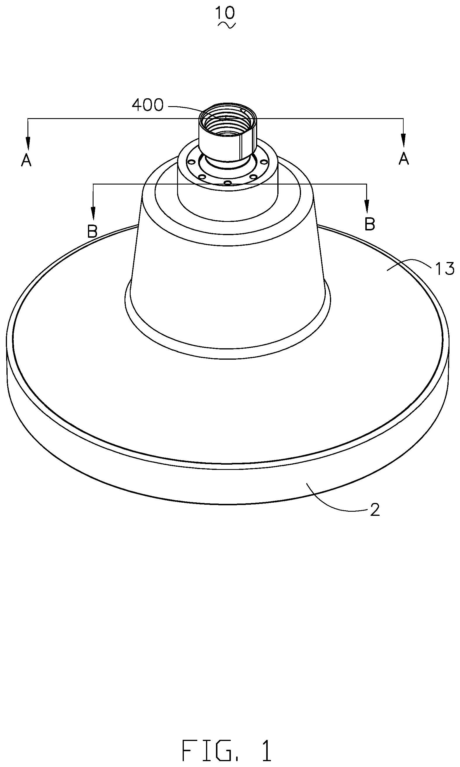
is an illustrative isometric view of a spray head according to a first embodiment of the present invention;
is an illustrative isometric view of the spray head shown in , but from another aspect;
is an exploded view of the spray head shown in ;
is an exploded view of the spray head shown in , but from another aspect;
is a cross-sectional view of the spray head taken along line A-A of ;
is a cross-sectional view of the spray head taken along line B-B of , but from another aspect, a filter media thereof being partially removed away;
is an isometric assembled of the spray head, a head portion and a case thereof being partially removed away;
is a cross-sectional view of the spray head shown in , a filter media thereof being partially removed away;
an illustrative isometric view of a water filter device according to a second embodiment of the present invention;
is an exploded view of the water filter device shown in ;
is an exploded view of the water filter device shown in , but from another aspect;
is a cross-sectional view of the water filter device shown in .
is an illustrative isometric view of a case of the water filter device shown in ;
is cross-sectional view of a water filter device according to a third embodiment of the present invention;
cross-sectional view of a water filter device according to a fourth embodiment of the present invention;
an illustrative isometric view of a water filter device according to a fifth embodiment of the present invention;
is a cross-sectional view of the water filter device shown in ;
is an illustrative isometric view of a case of the water filter device shown in .
DESCRIPTION OF EMBODIMENTS
The technical solutions of the present invention will be clearly and completely described below with reference to accompanying drawings and specific embodiments.
As shown in , a water filter device 3 of a first embodiment of the present invention adapts to be secured in a spray head 10 . The spray head 10 comprises a head portion 1 , a spray portion 2 mounted on the head portion 1 for forming a receiving cavity 11 together with the head portion 1 . The water filter device 3 received in the receiving cavity 11 . The head portion 1 is configured to deliver unfiltered water, represented by solid-line arrows, to the water filter device 3 and comprises a U-shaped central portion 12 , a supporting portion 13 protruded outwardly from the periphery of central portion 12 , and at least one leg portion 14 extending downwardly from the periphery of the supporting portion 13 for engaging with the spray portion 2 .
The spray portion 2 is attached to the head portion 11 . The spray portion 2 is two-piece type and comprises an inner part 21 and an outer part 22 covered on the inner part 21 and the head portion 1 . The inner part 21 comprises a baffle 211 , a receiving opening 212 provided on the middle of the baffle 211 , a fastening wall 213 projected from the baffle 211 and surrounding the receiving opening 212 for engaging with the water filter device 3 . The baffle 211 is a circular plate 214 and comprises a plurality of protruding portions 215 protruding from the circular plate 214 towards the outer part 22 of the spray portion 2 . Each of protruding portions 215 comprises at least one water outlet hole 216 . The plurality of protruding portions 215 may be arranged in different groups. Filtered water, represented by dotted-line arrows, flows to the water outlet holes 216 of the corresponding protruding portions 215 through the circular plate 214 of the baffle 211 and is discharged to form a spray pattern. The outer part 22 comprises a spray plate 221 and a surrounding wall 222 extending upwardly from the periphery of the spray plate 221 . The spray plate 221 comprises a middle opening 223 for receiving the water filter device 3 together with the receiving opening 212 and a plurality of apertures 224 surrounding the middle opening 223 in order. A part of each of the protruding portions 225 extends to the apertures 224 and is exposed out of the spray plate 221 , respectively.
The water filter device 3 comprises a case 4 having an inlet port 400 , a detachable portion 6 connected with the case 4 and easily disassembled and reassembled from the case 4 for forming an accommodation space 300 with the case 4 , a filter cartridge 5 received in the accommodation space 300 for dividing the accommodation space into an inlet chamber 401 and a redirected passage 402 sealed off from the inlet chamber 401 . The filter cartridge 5 and the detachable portion 6 are easily detachable and can be replaced, respectively.
The case 4 comprises a lateral 41 , a first portion 42 mounted on the lateral 41 for receiving the filter cartridge 5 together with the lateral 41 , a connecting portion 43 protruded outwardly from the periphery of the lateral 41 and positioned between the baffle 211 of the spray portion 2 and the supporting portion 13 of the head portion 1 and an engaging portion 44 extending from the periphery of the connecting portion 43 for engaging with the leg portion 14 of the head portion 1 . The first portion 42 of the case 4 is a circular plate. The lateral 41 of the case 4 is annular configuration and is surrounded by the central portion 12 of the head portion 1 . The lateral 41 of the case 4 and the central portion 12 of the head portion 1 are arranged so that the case 4 is shaped to match the head portion 1 .
The detachable portion 6 includes a second portion 61 opposite to the first portion 42 of the case 4 and a side portion 62 extending from the second portion 61 for abutting against the lateral 41 of the case 4 . The second portion 61 of the detachable portion 6 is a circular plate and the side portion 62 of the detachable portion 6 is annular configuration. In the present exemplary embodiment, the side portion 62 comprises a first fixing wall 621 inserted into the receiving opening 212 and abutting against the fastening wall 213 of the spray portion 2 , a second fixing wall 622 extending from the first fixing wall 621 and connected to the lateral 41 of the case 4 and at least an outlet port 404 drilled completely through the second fixing wall 622 . Optionally, an outlet port formed on the lateral of the case. The filtered water flows out from the outlet port of the lateral.
In the present exemplary embodiment, the inlet port 400 is provided on the first portion 42 and is in fluid connection with the inlet chamber 401 . Optionally, an inlet port is formed on the lateral and spaced apart from the outlet port 404 . While assembled, the case 4 is mounted on the inner part 21 of the spray portion 2 for forming a receiving chamber 405 fluidly coupling to the outlet port 404 and effectively delivering and guiding the filtered water to the protruding portions 215 via the outlet port 404 .
Accordingly, the first fixing wall 621 of the detachable portion 6 and the fastening wall 213 of the spray portion 2 can be secured together by threads, snap-fit, friction fit, etc., to fix the detachable portion 6 on the spray portion 2 . The lateral 41 of the case 4 and the second fixing wall 622 of the detachable portion 6 can be secured together by threads, snap-fit, friction fit, etc., to fluidly seal off the redirected passage 402 .
The filter cartridge 5 comprises a top portion 51 , a bottom 52 opposite to the top portion 51 , a sidewall 53 connected with the top portion 51 and the bottom 52 , and a cylindrical or tubular filter media 54 received therein. The top portion 51 comprises a plurality of inlet holes 55 and the bottom 52 comprises a plurality of guiding holes 56 . When assembled, the second fixing wall 622 is sandwiched between the lateral 41 of the case 4 and the sidewall 53 of the filter cartridge 5 . The redirected passage 402 is formed by the bottom 52 of the filter cartridge 5 together with the second portion 61 and the side portion 62 of the detachable portion 6 . In the present exemplary embodiment, the outlet port 404 is located below the bottom 52 of the filter cartridge 5 , so that the filtered water directly flows out from the outlet port 404 through the redirected passage 402 .
In usage state, when the unfiltered water enters into the inlet chamber 401 via the inlet port 400 and passes through the inlet holes 55 of the top portion 51 of the filter cartridge 5 will surround the filter cartridge 5 . The filtered water comes from the guiding holes 56 of the filter cartridge 5 via the bottom 52 thereof, flows down into the redirected passage 402 and is forced and redirected by the second portion 61 and the side portion 62 of the detachable portion 6 , thereby delivering and guiding the filtered water to flow into the receiving chamber 405 via the outlet port 404 , and then discharges out from the water outlet holes 216 of the protruding portions 215 .
Compared with the related art, the outlet port provides on the side portion of the detachable portion, so the filtered water can be redirected by the redirected passage and discharged out from the water filter device along a side direction of the water filter device, thereby the detachable portion can be easily disassembled and reassembled from the case and the spray portion. When replacing the filter cartridge, there is no need to remove the entire spray head, just directly remove the detachable portion from the spray portion and the case.
show a water filter 3 a device of a second embodiment of the present invention similar to that of the first embodiment of the present invention except that the water filter device 3 a adapted to be secured between an outlet end of a shower arm or waterpipe and a spray head in a known manner. The water filter device 3 a related to the present invention is preferably substantially cylindrical in shape and includes a case 4 a having an inlet port 400 a , a detachable portion 6 a connected with the case 4 a and easily disassembled and reassembled from the case 4 a for forming an accommodation space 300 a with the case 4 a , a filter cartridge 5 a received in the accommodation space 300 a for dividing the accommodation space 300 a into an inlet chamber 401 a and a redirected passage 402 a together with the case 4 a and the detachable portion 6 a . The inlet chamber 401 a is sealed off from the redirected passage 402 a . The inlet port 400 a is capable of delivering unfiltered water, represented by solid-line arrows, to the inlet chamber 401 a.
The case 4 a comprises a lateral 41 a , a first portion 42 a mounted on the lateral 41 a , and an outlet port 404 a drilled from an outer surface of the lateral 41 a completely through an inner surface of the lateral 41 a . The first portion 42 a of the case 4 a is a circular plate and the lateral 41 a of the case 4 a is annular configuration. In the present exemplary embodiment, the inlet port 400 a is formed on the lateral 41 a and spaced apart from the outlet port 404 a . The inlet port 400 a is in fluid connection with the outlet end of a shower arm or waterpipe and the outlet port 404 a is in fluid connection with the spray head. Optionally, an inlet port is formed on the first portion.
In the present exemplary embodiment, the case 4 a further comprises a separating wall 43 a received in the accommodation space 300 a for fixing the filter cartridge 5 a . The separating wall 43 a comprises a fixing portion 44 a opposite to the first portion 42 a and at least partly spaced apart from the lateral 41 a at a predetermined distance and an extending portion 45 a extending from the fixing portion 44 a and connecting to the lateral 41 a of the case 4 a . The lateral 41 a and separating wall 43 a are manufactured by injection molding, thereby forming an integral unit. Optionally, a lateral and a first portion is the type of one-piece.
The detachable portion 6 a includes a second portion 61 a opposite to the first portion 42 a of the case 4 a and a side portion 62 a and extending from the second portion 61 a for abutting against the lateral 41 a of the case 4 a . The second portion 61 a of the detachable portion 6 a is a circular plate and the side portion 62 a of the detachable portion 6 a is annular configuration.
Accordingly, the case 4 a and the detachable portion 6 a can be secured together by threads, snap-fit, friction fit, etc., to fix the detachable portion 6 on the case 4 a . In the present exemplary embodiment, the case 4 a and detachable portion 6 a may be fabricated in any desired manner, using any acceptable material, such as by molding a plastic material to form the two portions in such a manner that they are sized and dimensioned so as to be capable of being scalingly screwed together and apart. The case 4 a comprises an annular threaded lower portion and the detachable portion 6 a comprises an internally threaded annular upper portion secured to the annular threaded lower portion, thereby fluidly sealing the redirected passage 402 a.
The filter cartridge 5 a is mounted on the separating wall 43 a and captured within the accommodation space 300 a . The filter cartridge 5 a comprises a top portion 51 a mounted on the fixing portion 44 a of the case 4 a , a bottom 52 a opposite to the top portion 51 a , a sidewall 53 a connected with the top portion 51 a and the bottom 52 a and a cylindrical or tubular filter media 54 a received therein. The top portion 51 a comprises a plurality of inlet holes 55 a and the bottom 52 a comprises a plurality of guiding holes 56 a . When assembled, the redirected passage 402 a is formed by the bottom 52 a of the filter cartridge 5 a , the second portion 61 a and the side portion 62 a of the detachable portion 6 a . Optionally, a redirected passage is formed by the bottom of the filter cartridge, a lateral together with a second portion and a side portion of a detachable portion.
In the present exemplary embodiment, the outlet port 404 a provides above the top portion 51 a of the filter cartridge 5 a . Optionally, an outlet port faces the sidewall of the filter cartridge 5 a . When assembled, the redirected passage 402 a comprises a bottom passage 4021 a located below the bottom 52 a of the filter cartridge 5 a and a side passage 4022 a fluidly connected with the bottom passage 4021 a . The bottom passage 4021 a is formed by the bottom 52 a of the filter cartridge 5 a together with the second portion 61 a and the side portion 62 a of the detachable portion 6 . The side passage 4022 a is formed by the lateral 41 a of the case 4 a together with the sidewall 53 a of the filter cartridge 5 a.
In usage state, when the unfiltered water enters into the inlet chamber 401 a via the inlet port 400 a and passes through the inlet holes 55 a of the top portion 51 a of the filter cartridge 5 a will surround the filter media 54 a of the filter cartridge 5 a . Filtered water, represented by dotted-line arrows, comes from the guiding holes 56 a of the filter cartridge 5 a , flows down into the bottom passage 4021 a of the redirected passage 402 a and is forced and redirected by second portion 61 a and the side portion 62 a of the detachable portion 6 a , flows upwardly into the side passage 4022 a of the redirected passage 402 a , thereby delivering and guiding the filtered water to flow out from the outlet port 404 a.
Compared with the related art, the outlet port provides on the lateral of the case, so the filtered water can be redirected by the redirected passage and discharged from a side direction of the water filter device, thereby the detachable portion can be easily disassembled and reassembled from the case. When replacing the filter cartridge, there is no need to remove the entire water filter device and the spray head connected with the water filter device, just directly remove the detachable portion from the case.
A third embodiment of the present invention is shown in . shows a water filter device 3 b similar to that of the second embodiment of the present invention except that a position of an outlet port 404 b and a structure of a redirected passage 402 b . A water filter device 3 b related to the present invention is preferably substantially cylindrical in shape and includes a case 4 b having an inlet port 400 b , a detachable portion 6 b connected with the case 4 b and easily disassembled and reassembled from the case 4 b for forming an accommodation space 300 b with the case 4 b , a filter cartridge 5 b received in the accommodation space 300 b for dividing the accommodation space 300 b into an inlet chamber 401 b and a redirected passage 402 b sealed off from the inlet chamber 401 b . The inlet port 400 b is capable of the delivering unfiltered water, represented by solid-line arrows, to the inlet chamber 401 b.
The case 4 b comprises a lateral 41 b , a first portion 42 b mounted on the lateral 41 b , and an outlet port 404 b drilled from an outer surface of the lateral 41 b completely through an inner surface of the lateral 41 b . The first portion 42 b of the case 4 b is a circular plate and the lateral 41 b of the case 4 b is annular configuration. In the present exemplary embodiment, the inlet port 400 b is formed on the lateral 41 b and spaced apart from the outlet port 404 b . Optionally, an inlet port is formed on the first portion. The inlet port 400 b is in fluid connection with an outlet end of a shower arm or waterpipe and the outlet port 404 b is in fluid connection with a spray head.
The detachable portion 6 b includes a second portion 61 b opposite to the first portion 42 b of the case 4 b and a side portion 62 b and extending from the second portion 61 b for abutting against the lateral 41 b of the case 4 b . The second portion 61 b of the detachable portion 6 b is a circular plate and the side portion 62 b of the detachable portion 6 b is annular configuration.
Accordingly, the case 4 b and the detachable portion 6 b can be secured together by threads, snap-fit, friction fit, etc., to fix the detachable portion 6 b on the case 4 b . In the present exemplary embodiment, the case 4 b and detachable portion 6 b may be fabricated in any desired manner, using any acceptable material, such as by molding a plastic material to form the two portions in such a manner that they are sized and dimensioned so as to be capable of being sealingly screwed together and apart. The case 4 b comprises an annular threaded lower portion and the detachable portion 6 b comprises an internally threaded annular upper portion secured to the annular threaded lower portion, thereby fluidly sealing off the redirected passage 402 b.
The filter cartridge 5 b comprises a top portion 51 b , a bottom 52 b opposite to the top portion 51 b , a sidewall 53 b connected with the top portion 51 b and the bottom 52 b and a cylindrical or tubular filter media 54 b received therein. The top portion 51 b comprises a plurality of inlet holes 55 b and the bottom 52 b comprises a plurality of guiding holes 56 b . When assembled, the redirected passage 402 b is formed by the bottom 52 b of the filter cartridge 5 b together with the second portion 61 b and the side portion 62 b of the detachable portion 6 b . In the present exemplary embodiment, the outlet port 404 b is located below the bottom 52 b of the filter cartridge 5 b . Filtered water, represented by dotted-line arrows, directly flows out from the outlet port 404 b through the redirected passage 402 b.
In usage state, when the unfiltered water enters into the inlet chamber 401 b via the inlet port 400 b and passes through the inlet holes 55 b of the top portion 51 b of the filter cartridge 5 b will surround the filter cartridge 5 b . The filtered water comes from the guiding holes 56 b of the filter cartridge 5 b , flows down into the redirected passage 402 b and is forced and redirected by the second portion 61 b and the side portion 62 b of the detachable portion 6 b , thereby delivering and guiding the filtered water to flow out from the outlet port 404 b . The filtered water discharges from the filter cartridge 5 b in a different direction than the unfiltered water flows in the filter cartridge 5 b.
Compared with the related art, the outlet port provides on the side portion of the detachable portion, so the filtered water can be redirected by the redirected passage and discharged out from the water filter device along a side direction of the water filter device, thereby the detachable portion can be easily disassembled and reassembled from the case and the spray portion. When replacing the filter cartridge, there is no need to remove the entire water filter device and a spray head connected with the water filter device, just directly remove the detachable portion from the case.
A fourth embodiment of the present invention is shown in . shows a water filter device 3 c similar to that of the first, second or third embodiments of the present invention except that the side portion of the detachable portion can be omitted. The water filter device 3 c related to the present invention is preferably substantially cylindrical in shape and includes a case 4 c having an inlet port 400 c , a detachable portion 6 c connected with the case 3 c and easily disassembled and reassembled from the case 4 c for forming an accommodation space 300 c with the case 4 c , a filter cartridge 5 c received in the accommodation space 300 c for dividing the accommodation space 300 c into an inlet chamber 401 c and a redirected passage 402 c together with the case 4 c and the detachable portion 6 c . The inlet chamber 401 c is sealed off from the redirected passage 402 c . The inlet port 400 c is capable of delivering unfiltered water, represented by solid-line arrows, to the inlet chamber 401 c.
The case 4 c comprises a lateral 41 c , a first portion 42 c mounted on the lateral 41 c , and an outlet port 404 c drilled from an outer surface of the lateral 41 c completely through an inner surface of the lateral 41 c . The filter cartridge 5 c comprises a top portion 51 c , a bottom 52 c opposite to the top portion 51 c , a sidewall 53 c connected with the top portion 51 c and the bottom 52 c , and a cylindrical or tubular filter media 54 c received therein. The top portion 51 c comprises a plurality of inlet holes 55 c and the bottom 52 c comprises a plurality of guiding holes 56 c.
The detachable portion 6 c comprises a second portion 61 c directly abutting against the lateral 41 c . In the present exemplary embodiment, the outlet port 404 c provides below the bottom 52 c of the filter cartridge 5 c . When assembled, the redirected passage 402 c is formed by the bottom 52 c of the filter cartridge 5 c , the lateral 41 c of the case 4 c and the second portion 61 c of the detachable portion 6 c . Optionally, the outlet port provides above the top portion of the filter cartridge. When assembled, a redirected passage comprises a bottom passage located below the bottom of the filter cartridge and a side passage fluidly connected with the bottom passage. The bottom passage is formed by the bottom of the filter cartridge together with the lateral of the case and the second portion of the detachable portion. The side passage is formed by the lateral of the case together with the sidewall of the filter cartridge. It is understood that in an alternative exemplary embodiment, an outlet port faces the sidewall of the filter cartridge.
A fifth embodiment of the present invention is shown in . show a water filter device 3 d similar to that of the first, second, third or fourth embodiments of the present invention except that a structure of a filter cartridge 5 d . The water filter device 3 d related to the present invention is preferably substantially cylindrical in shape and includes a case 4 d having an inlet port 400 d , and a detachable portion 6 d connected with the case 4 d and easily disassembled and reassembled from the case 4 d for forming an accommodation space 300 d with the case 4 d . The filter cartridge 5 d received in the accommodation space 300 d for dividing the accommodation space 300 d into an inlet chamber 401 d and a redirected passage 402 d together with the case 4 d and the detachable portion 6 . The inlet chamber 401 d is sealed off from the redirected passage 402 d . The inlet port 400 d is capable of delivering unfiltered water, represented by solid-line arrows, to the inlet chamber 401 d.
The case 4 d comprises a lateral 41 d , a first portion 42 d mounted on the lateral 41 d , and an outlet port 404 d drilled from an outer surface of the lateral 41 d completely through an inner surface of the lateral 41 d , and a separating wall 43 d received in the accommodation space 300 a for fixing the filter cartridge 5 d surrounding the inlet chamber 401 d.
The filter cartridge 5 d comprises a top portion 51 d , a bottom 52 d opposite to the top portion 51 d , a sidewall 53 d connected with the top portion 51 d and the bottom 52 d . The material of the filter media is a filter cotton. The filter cartridge 5 d is composed of filter cotton elements stacked each other. Filtered water, represented by dotted-line arrows, flows out from the filter cartridge 5 d through the sidewall 53 d and the bottom 52 d thereof and enters into the redirected passage 402 d.
The detachable portion 6 d includes a second portion 61 d opposite to the first portion 42 d of the case 4 d and a side portion 62 d and extending from the second portion 61 d for abutting against the lateral 41 d of the case 4 d . The second portion 61 d of the detachable portion 6 d is a circular plate and the side portion 62 d of the detachable portion 6 d is annular configuration. Optionally, the side portion of the detachable portion can be omitted. A lateral directly abuts against a second portion of the detachable portion for forming a redirected passage.
The above are merely some embodiments of the present invention. It should be noted that for those of ordinary skill in the art, improvements can be made without departing from the inventive concept of the present invention, but these all fall into the protection scope of the present invention.
Figures (18)
Citations
This patent cites (2)
- US20040255377
- US20120055888