Holder for Mounting a Handheld Tool to a Surface
Abstract
A holder for mounting a hand tool to a surface has a suction cup positionable upon a surface. A yoke is connected to a central area of the suction cup, and is movable in a vertical direction relative to the surface, to distort the suction cup to secure the suction cup and yoke to the surface. A frame includes a cradle shaped to receive and support the hand tool, and a base. An extension connects the base and the cradle. A cam pin is movable within the frame, and has a cam profile that slides along the cam engagement surface of the yoke to displace the yoke along a vertical axis to increase or decrease the pressure between the suction cup and the surface.
Claims (17)
1. A holder for mounting a hand tool to a surface, the holder comprising: a suction cup positionable upon the surface, the suction cup having a central area; a yoke connected to the central area, the yoke movable in a vertical direction relative to the surface, to distort the suction cup and create an area of low pressure between the suction cup and the surface, to secure the suction cup and yoke to the surface, the yoke including a cam engagement surface; a frame including a cradle shaped to receive and support the hand tool when the hand tool is placed onto the holder; a base; an extension connecting the base and the cradle; and a cam pin movable within the frame, the cam pin including a cam profile slideably engageable with the cam engagement surface of the yoke to push the yoke vertically away from the surface or allow the yoke to move towards the surface to increase or decrease the pressure between the suction cup and the surface, wherein the yoke is biased by a resilient bumper.
Show 16 dependent claims
2. The holder of claim 1 , wherein the cradle includes at least two flexible legs.
3. The holder of claim 1 , wherein the frame is fabricated from resilient plastic.
4. The holder of claim 1 , wherein the cradle includes at least one of a projection or aperture, and wherein the hand tool includes the other of a mating aperture or projection, respectively, and wherein the projection and aperture mate when the hand tool is positioned within the cradle, to thereby maintain a predetermined position of the hand tool within the holder.
5. The holder of claim 1 , wherein the pin moves along a plane parallel to the surface when the holder is mounted to the surface.
6. The holder of claim 1 , wherein the pin passes through one or more apertures in the frame, and wherein an end of the pin forms an exposed button which can be pressed to move the pin.
7. The holder of claim 1 , wherein the cam profile of the cam pin extends at a depth within the cam pin that varies along a longitudinal axis of the cam pin.
8. The holder of claim 7 , wherein the cam profile faces away from the surface when the holder is positioned upon the surface.
9. The holder of claim 1 , wherein the cam engagement surface faces toward the surface when the holder is positioned upon the surface.
10. The holder of claim 9 , wherein the cam profile is oriented on a face of cam pin which faces away from the surface when the holder is positioned upon the surface, whereby the cam engagement surface is in operative engagement with the cam profile as the pin is moved.
11. The holder of claim 1 , wherein the yoke is biased in a direction of the surface relative to the frame, when the holder is mounted upon the surface.
12. The holder of claim 1 , wherein the bumper is affixed to the frame along a portion of its length, leaving a free portion in engagement with the yoke.
13. The holder of claim 12 , wherein the cradle is connected to the frame at a non-orthogonal angle with respect to the surface when the holder is connected to the surface using the suction cup.
14. The holder of claim 1 , wherein the yoke is co-molded to the suction cup.
15. The holder of claim 1 , wherein the yoke is a different material than the suction cup.
16. A kit comprising a container sized and dimensioned to house and limit free movement of at least the holder of claim 1 and the hand tool.
17. The kit of claim 16 , wherein the container is further sized and dimensioned to further house and limit free movement of a lancet driver tool, a plurality of lancets, a blood glucose reader, and a glucose test strip container.
Full Description
Show full text →
FIELD OF THE DISCLOSURE
The disclosure relates to a system and method for vibrating a body part to reduce pain during piercing or medical treatment of the skin, and more particularly to applying vibration using a handheld tool with a vibrating tip having protrusions, and further to a stand for supporting the handheld tool.
BACKGROUND OF THE DISCLOSURE
Procedures for reducing pain when injecting a material into the body, removing a body fluid or body tissue, or otherwise piercing the skin or body tissue, include (a) placing a very cold material against the skin or flesh of the patient at the piercing site, (b) applying a topical treatment to the skin or flesh at the piercing site, which temporarily numbs the skin or flesh or (c) rapidly manually massaging the skin or tissue at the injection site while performing the injection.
SUMMARY OF THE DISCLOSURE
In an embodiment of the disclosure, a holder for mounting a hand tool to a surface comprises: a suction cup positionable upon the surface, the suction cup having a central area; a yoke connected to the central area, the yoke movable in a vertical direction relative to the surface, to distort the suction cup and create an area of low pressure between the suction cup and the surface, to secure the suction cup and yoke to the surface, the yoke including a cam engagement surface; a frame including a cradle shaped to receive and support the hand tool when a hand tool is placed onto the holder; a base; an extension connecting the base and the cradle; and a cam pin movable within the frame, the cam pin including a cam profile slideably engageable with the cam engagement surface of the yoke to push the yoke vertically away from the surface or allow the yoke to move towards the surface to increase or decrease the pressure between the suction cup and the surface.
In variations thereof, the cradle includes at least two flexible legs; the frame is fabricated from resilient plastic; and/or the cradle includes at least one of a projection or aperture, and wherein the hand tool includes the other of a mating aperture or projection, respectively, and wherein the projection and aperture mate when the device is positioned within the cradle, to thereby maintain a predetermined position of the hand tool within the holder.
In other variations thereof, the cradle is connected to the frame at a non-orthogonal angle with respect to the surface when the holder is connected to the surface using the suction cup; the pin moves along a plane parallel to the surface when the holder is mounted to the surface; the pin passes through one or more apertures in the frame, and wherein an end of the pin forms an exposed button which can be pressed to move the pin; the cam profile of the cam pin extends at a depth within the cam pin that varies along a longitudinal axis of the cam pin; the cam profile faces away from the surface when the holder is positioned upon the surface; the cam engagement surface faces toward the mounting surface when the holder is positioned upon the mounting surface; and/or the cam profile is oriented on a face of cam pin which faces away from the mounting surface when the holder is positioned upon the surface, whereby the cam engagement surface is in operative engagement with the cam profile as the pin is moved.
In still further variations thereof, the yoke is biased in the direction of the surface relative to the frame, when the holder is mounted upon the surface; the yoke is biased by a resilient bumper; the bumper is affixed to the frame along a portion of its length, leaving a free portion in engagement with the yoke; the yoke is co-molded to the suction cup; and/or the yoke is a different material than the suction cup.
In another variation thereof, the device further includes a container sized and dimensioned to house and limit free movement of: the device of claim 1 , the hand tool, a lancet driver tool, a plurality of lancets, a blood glucose reader, and a container sized to contain glucose test strips.
BRIEF DESCRIPTION OF THE DRAWINGS
A more complete understanding of the present disclosure, and the attendant advantages and features thereof, will be more readily understood by reference to the following detailed description when considered in conjunction with the accompanying drawings wherein:
depicts a top view of a vibratory tip of the disclosure, having a plurality of nubs;
depicts a side view of the tip of ;
A depicts a detail view of a distal end of the tip of ;
B depicts alternative cross-sectional profiles for nubs of the disclosure;
depicts a perspective bottom view of an alternative vibratory tip of the disclosure, including an alternative arrangement of nubs;
depicts a top view of the tip of ;
depicts a distal end perspective view of the tip of ;
depicts a proximal end perspective view of the tip of ;
depicts a perspective top view of an alternative vibratory tip of the disclosure, including an alternative arrangement of nubs;
depicts a top perspective view of the tip of ;
depicts a side perspective view of the tip of ;
depicts a top view of a further alternative vibratory tip of the disclosure, including another arrangement of nubs;
A depicts a side view of an end of the extension arm of ;
B depicts a back view of the extension arm end of ;
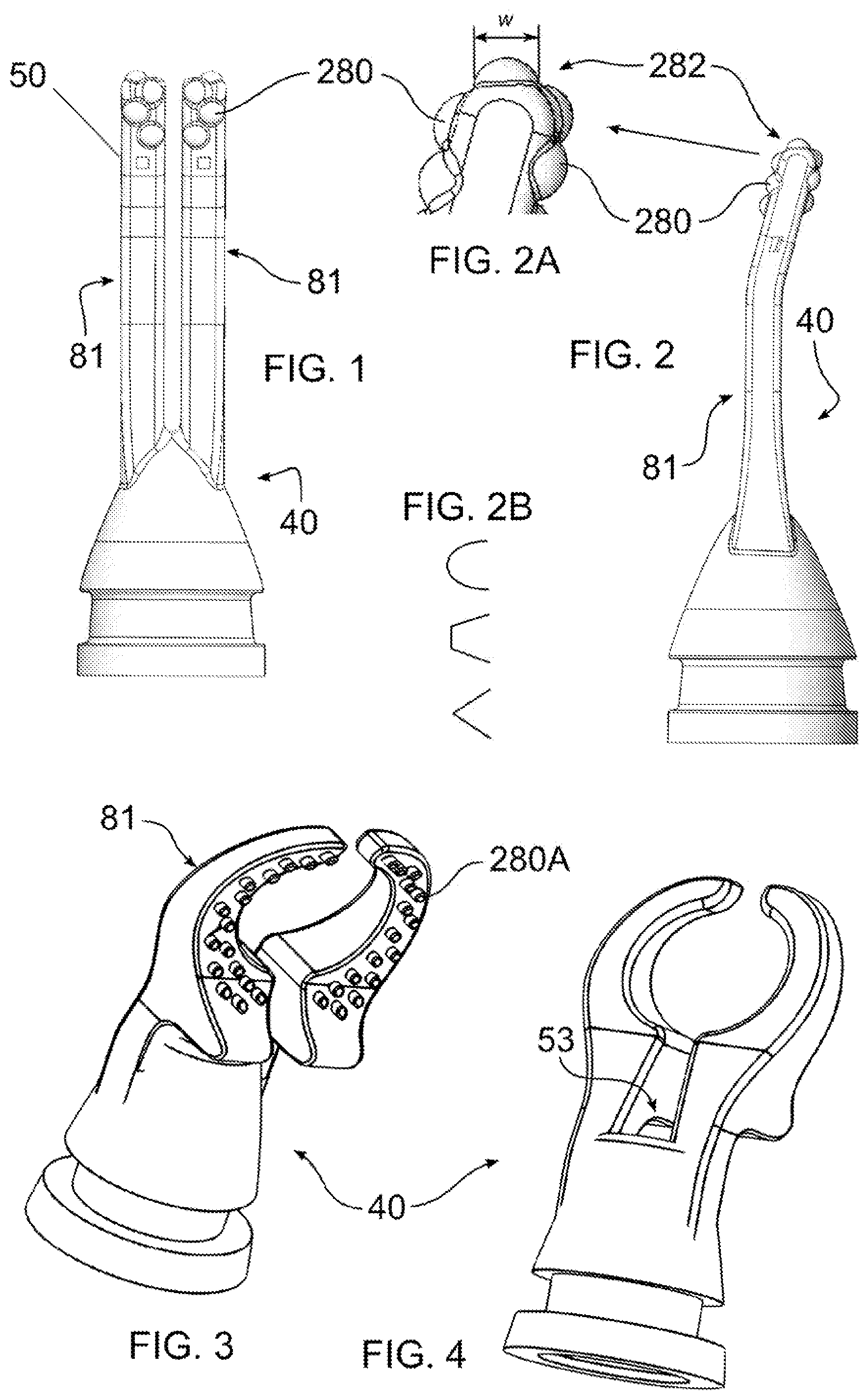
C depicts a front view of the extension arm end of ;
depicts a perspective side view of an instrument and holder of the disclosure;
depicts the instrument of , with a vibratory tip and holder removed;
depicts a cross-section of an alternative device of the disclosure, bisected approximately vertically;
depicts a top front perspective view of the holder of ;
depicts a rear perspective view of the holder of ;
depicts an exploded view of the holder of , with the suction cup, yoke, and cam pin removed;
depicts an exploded view of internal element of the holder of ;
depicts a bottom view of the holder of , with internal elements removed;
depicts a perspective view of a suction cup of the disclosure, with an unattached yoke;
depicts alternative tip shapes in accordance with the disclosure; and
depicts a kit containing an instrument of the disclosure and associated therapeutic elements.
DETAILED DESCRIPTION OF THE DISCLOSURE
As required, detailed embodiments are disclosed herein:
•
• however, it is to be understood that the disclosed embodiments are merely examples and that the systems and methods described below can be embodied in various forms. Therefore, specific structural and functional details disclosed herein are not to be interpreted as limiting, but merely as a basis for the claims and as a representative basis for teaching one skilled in the art to variously employ the present subject matter in virtually any appropriately detailed structure and function. Further, the terms and phrases used herein are not intended to be limiting, but rather, to provide an understandable description of the concepts.
The terms “a” or “an”, as used herein, are defined as one or more than one. The term plurality, as used herein, is defined as two or more than two. The term another, as used herein, is defined as at least a second or more. The terms “including” and “having.” as used herein, are defined as comprising (i.e., open language). The term “coupled.” as used herein, is defined as “connected.” although not necessarily directly, and not necessarily mechanically.
The disclosure reduces pain to a patient being injected, for example with an anesthetic, serum, vitamins, vaccine, or other medically efficacious liquid. The disclosure can be easily and inexpensively utilized during a medical, veterinary or dental procedure to almost completely or substantially eliminate the pain attendant an injection as it punctures the skin or flesh of the patient. The disclosure also reduces pain due to any disturbance of the skin our underlying tissues, for example the pain which accompanies puncture of the skin associated with removal of fluids from the body. Examples include while removing blood for a glucose test or other blood analysis; during a puncture associated with treatment of the skin, such as acne or blisters; and for other fluid withdrawals, for example during phlebotomy, paracentesis, aspiration, or synovial fluid withdrawal.
The disclosure provides a disposable tip and a hand-held apparatus, which in an embodiment has the form of an instrument 10 , for vibrating a skin or tissue area. In various embodiments, a vibrating end or tip 40 contacts at least two skin or tissue areas, or a circular skin or tissue area, immediately at an injection site, puncture site or site of a painful contact, and does so while the potentially painful therapeutic procedure takes place. Pain can be caused by injection, for example of a liquid anesthesia, serum, vitamins, vaccine, or other medical or dental efficacious material, into the skin or tissue at the injection site. Typically, a region of interest for a dentist can be the entire oral mucosa area and underlying bone, whereas the region of interest for a medical doctor can be the whole body and underlying bone. For a non-medical professional, the region of interest could be the fingertip or other area a lancet will prick to obtain blood for a glucose measure, for example. The disclosure is applicable to any of these situations, for any area of the body.
The method of the disclosure consists in vibrating tissue of a human or animal in proximity to a preselected puncture or injection site on the human or animal body while simultaneously puncturing or injecting by a needle or like instrument a liquid at the preselected site. The vibration can be effective if transmitted to a circular or other shaped area of body tissue, which can include bone underlying skin at a puncture or injection site, and particularly on opposite sides of the site.
Background helpful in understanding the disclosure can be found in the following documents, the contents of each of which are hereby incorporated herein by reference in their entirety:
•
• U.S. Patent Application 60/661,497 filed Sep. 20, 2004; • U.S. Patent Application 60/707,754 filed Aug. 12, 2005; • PCT Application PCT/US05/33769 filed Sep. 19, 2005; • U.S. Patent Application 61/163,945 filed Mar. 27, 2009; • PCT Application PCT/US09/66033 filed Nov. 29, 2009; • PCT Application PCT/US10/28858 filed Mar. 26, 2010; • U.S. patent application Ser. No. 13/179,674 filed Jul. 11, 2011, now U.S. Pat. No. 8,668,664; • U.S. patent application Ser. No. 13/225,782 filed Sep. 6, 2011, now U.S. Pat. No. 8,662,952; • U.S. patent application Ser. No. 13/253,572 filed Oct. 5, 2011; • PCT Application PCT/US12/53744 filed Sep. 5, 2012; • U.S. Patent Application 61/531,264 filed Sep. 6, 2011; • PCT Application PCT/US12/53943 filed Sep. 6, 2012; • U.S. Patent Application 61/909,544 filed Nov. 27, 2013; • PCT Application PCT/US14/67587 filed Nov. 26, 2014; • U.S. Patent Application 62/155,769 filed May 1, 2015; • U.S. patent application Ser. No. 14/803,535 filed Jul. 20, 2015; • U.S. Patent Application 62/208,860 filed Aug. 24, 2015; • International Patent Application Number PCT/US2016/029971 filed Apr. 29, 2016, and published as WO2016/178952 A1; and • International Patent Application Number PCT/US2016/029938 filed Apr. 29, 2016, and published as WO/2016/178941 A1.
With reference to , 14 , and 22 , an instrument 10 includes a handle 12 which contains a battery (not shown), and means to charge the battery, for example a cable, plug, or induction coil (not shown). A control circuit 28 is disposed within handle 12 , and controls the operation of a motor 24 . A switch 60 ( ) is pressed by a user of instrument 10 to cause the motor to start. A cam 100 A is connected to the motor output, and causes pivotal movement of a vibration transmitting rod 30 A about a pivot at O-ring 64 . A patient contacting tip 40 is connected to an end of rod 30 A opposite cam 100 A, and vibrates due to the eccentric path of cam 100 A. Tip 40 can have a smooth or rough surface, can include ridges or other shapes, or can include one or more nubs 280 positioned on a front, end, or back surface thereof. Nubs 280 facilitate transmission of vibration into the patient, which affects the nervous system of the patient to reduce a sensation of pain of the therapeutic procedure during vibration.
Handle 12 is shaped to be grasped by the hand of the user, thereby enabling instrument 12 to be used as a hand tool. A holder 400 A can be used to store or temporarily hold instrument 10 , or can be used to hold instrument 10 during a therapeutic procedure.
Tip 40 can be either permanently or removably mounted to handle 12 . In an embodiment, a twist lock connection is used to mount tip 40 . Alternatively, a snap-fit, magnetic, threaded connection, or interference fit, for example, can be used to releasably secure tip 40 to a remainder of instrument 10 .
In an embodiment of the disclosure, instrument 10 is fabricated with a minimal or no use of threaded fasteners, as these can tend to be vulnerable to loosening when instrument 10 is used to produce vibration at particular frequencies. This effect can be mitigated by using a thread locking compound or material. In an embodiment, motor 24 is mounted within handle 12 by being soldered or welded to metallic tabs which are adhered or co-molded with an interior portion of handle 12 . Likewise, battery contacts and other electrical or mechanical contacts can be inserted into retaining channels formed within a body or other component of handle 12 . Instrument 10 can further be improved by using lithium or state of the art batteries which reduce weight and/or provide an extended run time when charged.
In various embodiments of the disclosure, re-use of an end piece such as a vibrating tip of the instrument can be prevented, to avoid cross-contamination between patients. In one embodiment, the tip is broken when removed. In another embodiment, electromagnetic communication is established between an electronic tag on a tip and an electronic circuit within the body of the instrument. In this manner, a use count and validation of the tip can be monitored, and activation of the instrument can be disabled if the tip should be replaced after a period of time, or a predetermined number of uses, which are indicative of potential reuse between patients. In other embodiments, the tip can be re-used a number of times.
The embodiment disclosed herein is a tool for relieving pain associated with an injection, or any other piercing of the skin. For example, in addition to injections, the disclosure applies to other pain inducing procedures applied to any body tissue, such procedures including cauterizing, application of laser light, application of chemicals, or insertion of sutures, clips, or staples, or to pierce the skin to withdraw a sample of a body fluid. Further, it should be understood that the disclosure can be used to control the use of any tool tip, whether used in dentistry, general medicine, or within an industrial application, for example a grinding or boring machine tool tip, or other end effector.
Referring now to , a tip 40 is adapted to attach to an instrument 10 , to transmit vibration to a distal tip portion 50 , to thereby transmit the vibratory energy to the patient through contact with the treatment area. The vibration caused by contact with a device of the disclosure produces a therapeutic effect which results in a diminution of the sensation of pain associated with a therapeutic procedure, for example a skin puncture or excision, or a treatment of body tissue.
Tip 40 can have any of a variety of shapes, some of which are disclosed herein, which are adapted or adaptable to the shape and dimension of body tissue to be made less sensate to pain by a device of the disclosure. Such shapes can include for example pronged, ring shaped, and adapted to engage a finger. The tip can likewise have RFID or wireless features, and/or tearing or other reuse controlling features. For example, an RFID feature can be used to count, for example by a computing circuit within handle 12 , a number of times a tip 40 has been used, for example more than once, to prevent cross contamination between patients, and to maintain consistent performance. Tip 40 can include an overmold, and/or can be molded with different layers and components, to present a smooth external surface, and to prevent the intrusion of body fluids or other debris into instrument 10 .
With reference to A , tip 40 disclosed herein is additionally provided with nubs 280 having a small cross-sectional area with “w” relative to the cross-sectional area of an associated arm 81 . For example, w can be, for example, typically 0.25 mm to 3 mm, or as small as 0.05 and as large as 5 mm depending upon the size of the patient being treated and the cross-sectional area of arm 81 , and may be further provided with a pointed distal profile, a rounded distal profile as shown, an alternate shaped profile, or a combination of profiles. Non-limiting examples of oval, polygonal, and pointed nub 280 profiles are shown in B . In , the profile of nubs 280 A are truncated cylinders, which can have a flat distal end profile as shown, or which can have a distal end profile that forms an angle with respect to a longitudinal axis of the nub 280 A.
Referring again to , it may be seen that nubs 280 are positioned on two or more sides of arm 81 , as may be the case with any other nub shapes shown or described herein. In , nubs 280 ) are positioned on opposite sides and upon a distal end 282 of arms 81 , however they may be positioned on all sides, or any number of surfaces of arm 81 .
Without being bound to any particular theory, the inventors have found that nubs 280 / 280 A (hereinafter all nubs may collectively be referred to as 280 ) intensify the pain-relieving characteristics of tip 40 and instrument 10 . For example, the narrower distal shape of nub 280 may server to direct the vibratory energy more deeply into the skin. Further, the increased instance of points of contact with the skin may increase vibratory contact. Likewise, a combination of deeper skin penetration of vibration over a relatively greater number of contact points may result in an overall greater transfer of vibratory energy into the patient at the site of application of nubs 280 . Again, without being bound to a particular theory, a higher number of nerve sensors may be occupied conducting sensed vibratory contact, resulting in fewer nerve sensors carrying sensed pain, or nerve sensors may have a diminished capacity to convey sensed pain due to signals being conveyed relating to vibratory contact.
Additionally, by positioning one or more nubs 280 upon different sides of arm 81 , different parts of the patient's anatomy may be subjected to vibratory energy. For example, in the mouth, it would be possible to stimulate the gingivae and cheek simultaneously. It should be understood, however, that a different but beneficial therapeutic benefit can be obtained by providing a tip 40 without nubs 280 .
In the embodiment of , as with the embodiment of , a plurality of nubs 280 C are provided, positioned to extend from the front and back of arm 81 . In the embodiment of , there is only a single nub 280 C provided at each face, on each arm 81 . The presence of a single nub 280 C per face of arm 81 can serve to focus vibratory energy over a very small area, which may provide a different and useful effect, depending upon a particular therapeutic application, with respect to the multiple nubs 280 per face, as shown in . In a variation of , nub 280 C may be omitted on the front face 286 or rear face 288 . As can be seen in , arms 81 are spaced at opposite sides of gap, or alternatively adjacent a central lens 53 from which light is emitted.
In , it may be seen that nubs 280 may alternatively have the same size and shape whether they are positioned on the front, end, or back of arm 81 . While a plurality of numbs 280 are shown in , it should be understood that a single nub 280 can be provided upon any one of the front, end, and side portions of arm 81 .
In at least some embodiments of tip 40 , extension arms 81 can be bent to facilitate a therapeutic procedure using instrument 10 . For example, arms 81 can be bent to alter a fit between a cheek and gums, or otherwise bent to better fit the anatomy of a specific patient. In an embodiment, a wire or other stiff frame, for example of metal, can be placed into a mold prior to injection of overmolded thermoplastic or other material. Alternatively, the molded material can be selected from a material which at least substantially retains a shape once bent, and no underlying wire or frame is needed.
As can additionally be seen in , a light may be emitted at a location or lens 53 , and an RFID tag 370 ) can optionally be provided upon or within tip 40 .
In , for each arm 81 , nub 280 C has a curvature extending across a front face portion 286 ( A, 11 B ). Similarly, a nub 280 D extends across a rear face portion 288 ( A, 11 C ). In an embodiment, a size and location of a radius of the nubs 280 C at the front and rear facing portions 286 , 288 define curves having differing radius width and radial centers. In this manner, a shape of nubs 280 can be targeted very specifically to the anatomy typically found at a target usage site.
depicts a cross-section of an instrument 10 in accordance with the disclosure, which has an alternative tip engagement configuration with respect to that shown in . In , a vibration transmitting rod 30 A transmits motion produced within handle 12 to vibration along an exterior surface of tip 40 . Rod 30 A can optionally transmit light as well as vibration, for example by being fabricated with a light transmissive material or having a light channel, or by producing light within, to a lens 53 (not shown in ).
A base of rod 30 A includes a base recess 68 into which an eccentric cam 100 A rotates. An electric motor 24 is affixed to handle 12 , and has an output shaft 70 which is connected to circular cam 100 A having eccentric cam lobes 104 . Motor 24 can be controlled by an electronic circuit 28 , and can be activated by a switch 60 ( ), which either mechanically completes an electrical connection to motor 24 , or which signals to circuit 28 that it is desired to start motor 24 .
In an embodiment arms 81 have been found to produce a therapeutic pain relieving benefit if caused to vibrate at an amplitude of 0.1 to 5 mm, although a greater or lesser amplitude is possible, if a therapeutic procedure indicates such a need. It should be understood that amplitude will vary whether arms 81 are suspended in air, or pressed with a light pressure on the skin. The foregoing values are for amplitude based upon a light pressure upon the skin. Amplitude in air may be greater, for example 2.0-2.5 mm, which results in amplitude of 1.0-1.5 mm with light pressure upon the skin. Greater amplitude can be created, for example, by using a lower frequency and increasing power to motor 24 . A frequency within the range of 100 to 300 Hz has been found to be therapeutically beneficial for reducing pain, although a slower or faster frequency can be effective.
Without being bound to any particular theory, it appears that by cycling or pulsing as described, the brain does not get accustomed to, or habituate to the vibration, and thus the vibrations remain effective. Patterns and durations of pulsing or cycling can be used, as best determined by the practitioner as observed to reduce habituation to the vibration among various patients or patient demographics. To this end the electronic circuit 28 can be used to control pulsing to obtain a desired on/off duty cycle. The medical practitioner can apply vibration using instrument 10 for a period prior to potentially causing pain, for example for a period of 1 to 90 seconds, and can continue to apply pressure after treatment, also for a period of 1 to 90 seconds, depending on the body tissue affected, tip shape selected, and the type of treatment, for example.
In an embodiment for one type of therapeutic procedure, motor 24 is energized using one or more lithium batteries. The vibration at the free ends of arms 81 can vary from about 1.0 mm to about 3.0 mm, in an embodiment advantageously 1.5 mm to 2.0 mm. In some embodiments, the vibrating tip is placed on or near the location for anywhere from around 3 seconds to around 15 seconds, with the vibration continually applied. In other embodiments, a duty cycle of about 1.05 seconds with on pulsing of about 1 sec. and off of about 0.05 seconds is used. Depending on a patient's physiology and the desired application, at least one of the vibration amplitude and duty cycle can be varied to be more effective.
A nozzle 34 is affixed to handle 12 , and includes an internal support 62 for an O-ring 64 . Vibration transmitting rod 30 A passes through and is pivotably supported by O-ring 64 . As cam 100 A rotates, base recess moves in an orbit about output shaft 70 , which orbital motion is translated to a distal end 72 of vibration transmitting rod 30 A via pivoting about O-ring 64 . Distal end 72 inserts into a recess 74 within tip 40 . Rod 30 A and tip 40 can be attached by any other means, including alternatively providing an extension on tip 40 which inserts into a recess in distal end 72 , or distal end 72 and tip 40 can be attached by a fastener, magnet, or other means. Such attachment means is advantageously releasable, so that a new tip 40 can be used for each new patient or treatment.
An overmold or sleeve 76 can be provided to prevent passage of debris between an exterior of instrument 10 and an interior of nozzle 34 . Tip 40 can be separated from instrument 10 together with sleeve 76 , nozzle 34 , and transmitting rod 30 A. Alternatively, tip 40 can be removed together with or separated from sleeve 76 , leaving the remaining components in connection with instrument 10 , or may be removed together with various combinations of these elements. In an embodiment, nozzle 34 forms a twist-lock connection with handle 12 , whereby tip 40 can be removed or attached to instrument 10 by radial rotation of tip 40 including nozzle 34 with respect to handle 12 .
With reference to , an instrument 10 cooperative with a tip 40 , is supported by a mounting base or holder 400 A. A suction cup 430 A is positioned at a one end of a base extension 404 A, and an instrument holder 412 is positioned at an opposite end of extension 404 A. Holder 400 A can be sized and shaped to releasably and securely retain any instrument 10 of the disclosure as described herein. illustrates an embodiment of instrument 10 without a tip 40 attached, in accordance with one embodiment of tip 40 .
Instrument holder 412 is shaped to slidingly and releasably retain handle 12 of instrument 10 , and can form a tapered profile which mates with a tapered profile of handle 12 , to enables insertion of instrument 10 to a desired predetermined extent, whereby a sufficient portion of handle 12 extends from holder 412 to enable handle 12 to be easily grasped and pulled to remove instrument 10 . As an alternative to a tapered fit, handle 12 can be shaped to contact a surface of instrument 10 to prevent insertion beyond a desired predetermined extent.
In addition, or as an alternative to the foregoing, holder 412 and handle 12 can be provided with mating detent portions, such as a protrusion 442 A on one part, and a recess 444 A on another, which engage when instrument 10 has been inserted sufficiently. In the embodiment shown, protrusion 442 A is disposed on one or more of a resilient cradle arm 414 , integrally molded with holder 412 . Recess 444 A is disposed within handle 12 , although it should be understood that a recess can be provided within holder 412 , and a protrusion can be provided upon handle 12 . When instrument 10 is inserted, cradle arm 414 bends to enable protrusion 442 A to be displaced by handle 12 . When protrusion 442 A is aligned with recess 444 A, cradle arm 414 pushes protrusion 442 A into recess 444 A. An alignment of protrusion 442 A and recess 444 A can be achieved by mating surfaces in an interior surface of holder 412 , and corresponding mating exterior surfaces of instrument 10 , which contact each other to mutually guide and orient instrument 10 as it is inserted into holder 412 .
While a vibratory instrument 10 is illustrated and described, it should be understood that holder 400 A of the disclosure can be used with any hand tool, wherein a cradle formed of one or more cradle arms 414 is adapted to the shape of the particular hand tool, and wherein protrusions 442 A or recess 444 A are provided on the adapted cradle and hand tool, respectively.
Holder 412 includes two opposed cradle arms 414 , 416 which can be formed with a resilient material, whereby cradle arms 414 / 416 can bend to enable engagement and disengagement of the mating portions 442 A, 444 A. Alternatively, resilient cradle arms 414 , 416 can be formed to define, when relaxed, an interior diameter which is smaller than a diameter of instrument 10 or handle 12 , whereby a wedging force is achieved when instrument 10 has been inserted, which causes instrument 10 to be securely retained between cradle arms 414 when sufficiently inserted.
Holder 412 can further be disposed at an angle with respect to a plane defined by a bottom of suction cup 430 A, which is intended to be secured upon a mounting surface 540 upon which holder 400 A is to be mounted. In this manner, gravity can be employed to retain instrument 10 within holder 412 . In the embodiment shown, an angle of 15 degrees is formed, although any angle can be used, for example anywhere from 10 to 30 degrees, although any angle between zero and vertical, inclusive, can be used in accordance with the disclosure. In an embodiment, the angle can be selected by rotating holder 412 about a pivot (not shown) which connects holder 412 to base extension 404 A.
Base extension 404 A increases a height of holder 412 above a surface to which device stand 400 is mounted. In this manner, tip 40 does not contact the surface when instrument 10 is in holder 412 , and handle 12 is spaced from the surface to be easily grasped by a hand.
With reference to , suction cup 430 A is positioned beneath a circular base 420 A, the latter being attached to base extension 404 A. Suction cup 430 A includes a planar suction base 426 A, and a peripheral wall 426 B extending vertically, with respect to a mounted position, from suction base 426 A, which surrounds and orients circular base 420 A with respect to suction cup 430 A.
Suction cup 430 A is connected at a center of suction base 426 A to a yoke 432 A, the latter forming an aperture 452 . In , yoke 432 A and suction base 426 A are integrally formed or co-molded together. illustrates that yoke 432 A and suction base 426 A can alternatively be formed as separated parts joined by any known method, such as a fastener, including adhesive.
A cam engagement surface 434 A is provided upon yoke 432 A, facing towards aperture 452 . Yoke 432 A is inserted within a channel 436 A formed within base extension 404 , to be slideable vertically with respect to a mounting plane of holder 400 A. Suction cup, through attachment to yoke 432 A, has the ability to swivel or flex laterally and to thereby lie flat upon a mounting surface 540 adjusting for irregularities in the shape of parts or in mounting surface 540 . In an embodiment, cam engagement surface 434 A faces toward the mounting surface when holder 400 A is positioned upon the mounting surface.
A cam pin 454 passes through yoke aperture 452 , and is slideably supported by opposed apertures 456 formed in base extension 404 . Cam pin 454 includes a cam profile 458 which engages yoke cam engagement surface 434 A, to raise and lower yoke 432 A vertically, as cam pin 454 is moved horizontally, with respect to a plane of a mounting surface of holder 400 A. When a relatively deep area 458 ′ of cam profile 458 engages cam engagement surface 434 A, suction base 426 A is permitted to form a planar shape, and suction between suction base 426 A and a mounting surface 540 ) (not shown) is released, enabling holder 400 to be removed from mounting surface 540 ). In an embodiment, cam profile 458 extends at a depth within cam pin 454 that varies along a longitudinal axis of cam pin 454 . In an embodiment, when the cam engagement surface 434 A faces toward the mounting surface, cam profile 458 is oriented on a face of cam pin 454 which faces away from the mounting surface when holder 400 A is positioned upon the mounting surface, whereby cam engagement surface 434 A is driven into operative engagement with cam profile 458 .
When suction cup 430 A is in planar, sealing contact with mounting surface 540 , and cam pin 454 is moved to gradually place a relatively shallow area 458 ″ of cam profile 458 into engagement with cam engagement surface 434 A. In so doing, a center area of suction base 426 A is pulled vertically, distorting the suction base to form an area of low pressure between suction base 426 A and the mounting surface. More particularly the distorted area can have, for example, a conical or tented shape (not shown), with the vacuum present within the tented shape, thereby attaching suction cup 430 A to mounting surface 540 , and affixing holder 400 to mounting surface 540 . Opposed ends of cam pin 454 form buttons two buttons 462 , either of which extend from base extension 404 A, and which may alternately be pushed to move cam pin 454 into engagement with either deep or narrow area 458 ′, 458 ″, to create or release suction to engage or release holder 400 .
A resilient bumper 464 is positioned to have an upper end 466 secured within base extension 404 A, and a lower end 468 that freely extends within base extension 404 A to lie in deformable contact with an upper portion of yoke 432 A. Bumper 464 functions to continuously urge cam engagement surface 434 A into contact with cam profile 458 , and to press upon instrument 10 when suction cup 430 A is engaged with a mounting surface 540 . In an embodiment, a portion of yoke upper end 466 can be secured within base extension 404 A to freely extend into a space between cradle arms 414 , whereby when instrument 10 is inserted into holder 400 A, upper end 466 resiliently engages instrument 10 , for example by pressing upon handle 12 or other portion of instrument 10 , to contribute to securely holding instrument 10 within holder 400 A and in contact with cradle arms 414 , 416 , whereby instrument 10 may be used ‘hands free’ without excessive movement or displacement due to vibration. Another form of biasing element can be used for bumper 464 , including for example a coil or leaf spring, secured in a manner as described above.
Holder 400 A can be fabricated of any material, for example metal, wood, plastic, including injection molded plastic, or composite material. Plastic is advantageous as it can be used in a clinical environment, and can be machine washed or wiped with disinfectant cleaners without being damaged. Further, plastic can be selected to be inherently resilient, thereby facilitating the formation of resilient cradle arms 414 . However, other materials can also be used for some or all of holder 400 A, in particular metal, including shape metal alloys, for example. Non-limiting examples include thermoplastics such as Acrylic, ABS, Nylon, PLA, Poly benzimidazole, Polycarbonate, Polyether sulfone, Polyetherether ketone, Polyetherimide, Polyethylene, Polyphenylene oxide, Polyphenylene sulfide, Polypropylene, Polystyrene, Polyvinyl chloride, and Teflon.
Suction cup 430 A can be fabricated from any of the foregoing materials which are soft and pliable at room temperature, further including rubber or a polymeric analog, such as a thermoplastic elastomer, which can be a Styrenic block copolymers (TPE-s), Thermoplastic olefins (TPE-o), Elastomeric alloys (TPE-v or TPV), Thermoplastic polyurethanes (TPU), Thermoplastic copolyester. Thermoplastic polyamides. Other materials can include natural or synthetic rubber, or silicone based materials, as understood within the art. Similar materials can be used for bumper 464 .
Holder 400 A can be fabricated using any known method which can produce parts as a unit, as shown, or in portions which can be assembled, for example by gluing, riveting, heat welding, snap fitting, or interference fitting, for example. Parts can be produced by extrusion, grinding, molding, 3D printing, casting, or any other suitable method. A finish can be formed during production, or a coating or painted finish can be applied after production.
Accordingly, the disclosure provides a mounting base and holding system for table or wall mounting of an instrument of the disclosure. In use, holder 400 A, including suction cup 430 A, are pressed firmly downward against the surface 540 ) upon which holder 400 A is to be mounted, by the user. In the process of this action the suction cup 430 A is flattened at least partially and displaces air beneath it, until base 420 presses against a circular upper surface of suction base 420 A. To increase suction, pin 454 is moved laterally, further raising a center of suction base 420 A. Alternatively, substantially all suction is created by moving pin 454 laterally.
With reference to , alternative tip 40 shapes are presented, including elongate loop 40 A, short hook 40 B, ring 40 C, open box 40 D, fork 40 E, single shaft 40 F, single shaft with terminating bumps 40 G, curved hook 40 H, L-shape 40 J, and open hook 40 K. A medical practitioner can select a particular shape which best fits the anatomical treatment site, and which best transmits therapeutic vibration to the patient for the purposes stated herein. As with other embodiments of tip 40 described herein, the shaped tips 40 A- 40 J can be bent to, for example, alter the desired shape to improve a fit, visibility, or to match a shape which has demonstrated improved results. For various tip shapes, it can be advantageous to orient body tissue at an angle with respect to a longitudinal axis of vibration of tip 40 . For example, with reference to the tip of , a finger is placed orthogonal to a longitudinal axis of handle 12 , a side portion of the finger thereby abutting both stop members 90 . An injection, for example, can thereafter be made through the circular opening 92 .
depicts a kit 600 containing instrument 10 , holder 400 A, and components useful for a therapeutic treatment for diabetes. While kit 600 is targeted to diabetes, it should be understood that other kits can be formed which include instrument 10 and holder 400 A, to be used for reducing pain in other therapeutic procedures. In the embodiment of , kit 600 includes a sealable case 602 , a lancing device 604 , lancets 606 , instrument 10 , holder 400 A, a container of test strips 608 , and a blood glucose analyzer 610 , supported in a pouch 612 .
All references cited herein are expressly incorporated by reference in their entirety. It will be appreciated by persons skilled in the art that the present disclosure is not limited to what has been particularly shown and described herein above. In addition, unless mention was made above to the contrary, it should be noted that all of the accompanying drawings are not to scale. There are many different features to the present disclosure and it is contemplated that these features may be used together or separately. Thus, the disclosure should not be limited to any particular combination of features or to a particular application of the disclosure. Further, it should be understood that variations and modifications of the subject matter of the disclosure might occur to those skilled in the art to which the disclosure pertains. Accordingly, all expedient modifications readily attainable by one versed in the art from the disclosure set forth herein that are in accordance with the disclosure are to be included as further embodiments of the present disclosure.
DRAWING REFERENCES
•
• 10 Instrument: 12 Handle: 24 Motor: 28 Electronic Circuit: 30 A Vibration Transmitting Rod: 34 Nozzle: 40 , 40 A-H, 40 J-K Tip: 50 Distal Tip Portion: 53 Lens: 60 Switch: 62 O-ring Support; 64 O-ring; 68 Rod Base Recess; 70 Output Shaft; 72 Rod Distal End; 74 Tip Recess; 76 Sleeve; 81 Arm; 100 A Cam; 104 Cam Lobes; 280 , 280 A-D Nubs; 282 Arm Distal End; 286 Arm Front Face Portion; 288 Arm Rear Face Portion; 370 RFID Tag; 400 Mounting Base; 400 A Holder; 404 A Base Extension; 412 Instrument Holder; 414 Cradle Arm; 416 Cradle Arm; 420 A Circular Base; 426 A Planar Suction Base; 426 B Peripheral Wall; 430 A Suction Cup; 432 A Yoke; 434 A Cam Engagement; 436 A Base Channel; 442 A Handle or Holder Protrusion; 444 A Handle or Holder Detent; 452 Yoke Aperture; 454 Cam Pin; 456 Base Apertures; 458 Cam Profile; 458 ′ Cam Profile Deep Area; 458 ′ Cam Profile Shallow Area; 462 Cam Pin Buttons; 464 Resilient Bumper; 466 Bumper Upper End; 468 Bumper 10 Lower End; 540 Mounting Surface; 600 Kit; 602 Case; 604 Lancing Device; 606 Lancets; 608 Container of Test Strips; 610 Blood Glucose Analyzer; 612 Pouch.
Figures (6)
Citations
This patent cites (143)
- US1485963
- US2247258
- US2258857
- US2574945
- US3590232
- US3620209
- US3837595
- US4091805
- US4572180
- US4593973
- US4785796
- US4867141
- US5437606
- US5542845
- US5611771
- US5636988
- US5639238
- US5647851
- US5647853
- US5692900
- US5704902
- US5928170
- US5938435
- US5989022
- US6030210
- US6355007
- US6436035
- US6502794
- US6602229
- US6923762
- US7244266
- US7527231
- US7815155
- US7981071
- US8121696
- US8622952
- US8668664
- US8690872
- US8777897
- US8940008
- US9168340
- US9200667
- US9463287
- US9539171
- US9675766
- US9732785
- US10363380
- US10695508
- US20020082564
- US20030040714
- US20030195644
- US20030225429
- US20040077977
- US20040254599
- US20050215952
- US20060106363
- US20070088245
- US20070145155
- US20070150004
- US20070156179
- US20070167943
- US20080017764
- US20080086159
- US20080215039
- US20080195006
- US20080255483
- US20090047624
- US20090108153
- US20090281464
- US20100125172
- US20100179457
- US20110054386
- US20110101182
- US20110226922
- US20110226924
- US20110270154
- US20110319812
- US20120016292
- US20120029422
- US20120070799
- US20120292467
- US20130095508
- US20130197317
- US20130204202
- US20130317314
- US20130334069
- US20140055588
- US20140121557
- US20140131412
- US20140187870
- US20140188095
- US20140188107
- US20140188128
- US20140316310
- US20140343432
- US20140371542
- US20140378940
- US20150121557
- US20150134358
- US20150136922
- US20150186702
- US20150216618
- US20150245126
- US20150306286
- US20170021113
- US20180264205
- US2010229783
- US2756890
- US2580792
- US3089618
- US102473201
- US102473201
- US103826686
- US103826686
- USZL201080016524.X
- US111757989
- US2411074
- US2699083
- US15355
- USS6154832
- US548916
- US2002224183
- US2004129914
- US5549987
- US2012/0124742
- US2012/0124742
- US2011141339
- US2523203
- US728859
- US2004000196
- US2006/034324
- US2008/042936
- US2010/110823
- US2010/111611
- US2011005634
- US2012/163411
- US2012/0163411
- US2013/036625
- US2013036507
- US2014/011740
- US2015/081181
- US2016/178952
- US3024513