Abstract
A cargo carrying strap system is discussed, the strap system having a handle assembly and one or more vertical straps for wrapping around a vertical perimeter of a piece of cargo. The strap system can further include a perimeter strap for wrapping around an edge perimeter of the cargo and a horizontal strap for wrapping around a horizontal perimeter of the cargo.
Claims (20)
1. A strap system for lifting and carrying cargo, the system comprising: a) a strap assembly for placement on top of the cargo, the strap assembly further comprising a handle operatively coupled to a planar handle base configured for providing rigidity and stability to the strap assembly; b) at least one vertical strap operatively attached to the strap assembly between the handle and the planar handle base with at least one fastener extending through the handle, the at least one vertical strap, and then the planar handle base, the at least one vertical strap configured for wrapping around a vertical perimeter of the cargo; c) a connector strap disposed on the at least one vertical strap, the connector strap further comprising second releasable strap connectors; and d) a horizontal strap for releasably attaching to the second releasable strap connectors of the connector strap, wherein the combination of the horizontal strap releasably attached to the connector strap is configured for wrapping around a horizontal perimeter of the cargo.
12. A method for lifting and carrying cargo, comprising: a) placing a strap system onto the cargo, the strap system comprising: i) a strap assembly for placement on top of the cargo, the strap assembly further comprising a handle operatively coupled to a planar handle base configured for providing rigidity and stability to the strap assembly, ii) at least one vertical strap operatively attached to the strap assembly between the handle and the planar handle base with at least one fastener extending through the handle, the at least one vertical strap, and then the planar handle base, the at least one vertical strap configured for wrapping around a vertical perimeter of the cargo, iii) a connector strap disposed on the at least one vertical strap, the connector strap further comprising second releasable strap connectors, and iv) a horizontal strap for releasably attaching to the second releasable strap connectors of the connector strap, wherein the combination of the horizontal strap releasably attached to the connector strap is configured for wrapping around a horizontal perimeter of the cargo; b) fastening the strap system to the cargo; and c) carrying out a step of one or both of lifting and carrying the cargo.
Show 18 dependent claims
2. The strap system as set forth in claim 1 , wherein the at least one vertical strap further comprises a first releasable strap connector.
3. The strap system as set forth in claim 1 , wherein the planar handle base is rectangular.
4. The strap system as set forth in claim 1 , wherein the at least one fastener comprises one or more of threaded fasteners, rivets, grommets, threaded stitching, and adhesive.
5. The strap system as set forth in claim 1 , further comprising an edge perimeter strap configured for wrapping around an edge perimeter of the cargo, the edge perimeter strap configured for releasably attaching to the strap assembly.
6. The strap system as set forth in claim 5 , further comprising third releasable strap connectors disposed on opposing ends of the strap assembly configured for releasably attaching to the edge perimeter strap.
7. The strap system as set forth in claim 1 , wherein the horizontal strap is orthogonal to the at least one vertical strap.
8. The strap system as set forth in claim 5 , wherein the edge perimeter strap is orthogonal to the at least one vertical strap.
9. The strap system as set forth in claim 5 , wherein the edge perimeter strap is orthogonal to the horizontal strap.
10. The strap system as set forth in claim 5 , wherein the edge perimeter strap is orthogonal to both the at least one vertical strap and the horizontal strap.
11. The strap system as set forth in claim 1 , wherein the connector strap is configured to move freely on the at least one vertical strap.
13. The method as set forth in claim 12 , wherein the at least one vertical strap further comprises a first releasable strap connector.
14. The method as set forth in claim 12 , wherein the at least one fastener comprises one or more of threaded fasteners, rivets, grommets, threaded stitching, and adhesive.
15. The method as set forth in claim 12 , wherein the horizontal strap is orthogonal to the at least one vertical strap.
16. The method as set forth in claim 12 , wherein the strap system further comprises an edge perimeter strap configured for wrapping around an edge perimeter of the cargo, the edge perimeter strap configured for releasably attaching to the strap assembly.
17. The method as set forth in claim 16 , wherein the strap system further comprises third releasable strap connectors disposed on opposing ends of the strap assembly configured for releasably attaching to the edge perimeter strap.
18. The method as set forth in claim 16 , wherein the edge perimeter strap is orthogonal to the at least one vertical strap.
19. The method as set forth in claim 16 , wherein the edge perimeter strap is orthogonal to the horizontal strap.
20. The method as set forth in claim 12 , wherein the connector strap is configured to move freely on the at least one vertical strap.
Full Description
Show full text →
CROSS-REFERENCE TO RELATED APPLICATIONS
This application claims priority of U.S. Provisional Patent Application Ser. No. 63/075,698 filed Sep. 8, 2020, which is incorporated by reference into this application in its entirety.
TECHNICAL FIELD
The present disclosure is related to the field of cargo carrying straps, in particular, cargo carrying strap systems that can be easily attached to, and detached from, cargo such as boxes, cases and the like.
BACKGROUND
Goods packaged in large or odd-shaped boxes can be awkward or difficult to lift and carry, especially if the boxes lack handholds or openings for grasping and carrying. For example, flat-screen televisions often are packed in cardboard boxes that are wide and tall but thin in depth and often require two persons to carry due to the awkwardness in carrying such a box. In other circumstances, storage cases or suitcases may have a handle but may be too narrow or difficult to grasp or may have had the handle broken off making lifting and carrying of such cases difficult or impossible.
It is, therefore, desirable to provide a cargo carrying strap system that can be easily attached to, and detached from, the boxes and cases described above to enable the lifting and carrying thereof.
SUMMARY
In some embodiments, a cargo carrying strap system can be provided, the strap system comprising a handle assembly and one or more vertical straps for wrapping around a vertical perimeter of a piece of cargo. In some embodiments, the strap system can further comprise a perimeter strap for wrapping around an edge perimeter of the cargo. In some embodiments, the strap system can further comprise a horizontal strap for wrapping around a horizontal perimeter of the cargo.
Broadly stated, in some embodiments, a strap system can be provide for lifting and carrying cargo, the system comprising: a handle assembly configured for placement on top of the cargo; and at least one vertical strap operatively coupled to the handle assembly, the at least one vertical strap configured for wrapping around the cargo in a vertical direction.
Broadly stated, in some embodiments, the at least one vertical strap can further comprise a first releasable strap connector.
Broadly stated, in some embodiments, the handle assembly can further comprise a handle operatively coupled to a handle base.
Broadly stated, in some embodiments, the handle and the at least one vertical strap can be coupled to the handle base with at least one fastener.
Broadly stated, in some embodiments, the at least one fastener can comprise one or more of threaded fasteners, rivets, grommets, threaded stitching and adhesive.
Broadly stated, in some embodiments, the strap system can further comprise a horizontal strap configured for wrapping around a horizontal perimeter of the cargo, the horizontal strap configured for releasably attaching to the at least one vertical strap.
Broadly stated, in some embodiments, the strap system can further comprise a connector strap disposed on the at least one vertical strap, the connector strap further comprising second releasable strap connectors configured for releasably attaching to the horizontal strap.
Broadly stated, in some embodiments, the system can further comprise a perimeter strap configured for wrapping around an edge perimeter of the cargo, the perimeter strap configured for releasably attaching to the handle assembly.
Broadly stated, in some embodiments, the strap system can further comprise third releasable strap connectors disposed on opposing ends of the handle assembly configured for releasably attaching to the perimeter strap.
BRIEF DESCRIPTION OF THE DRAWINGS
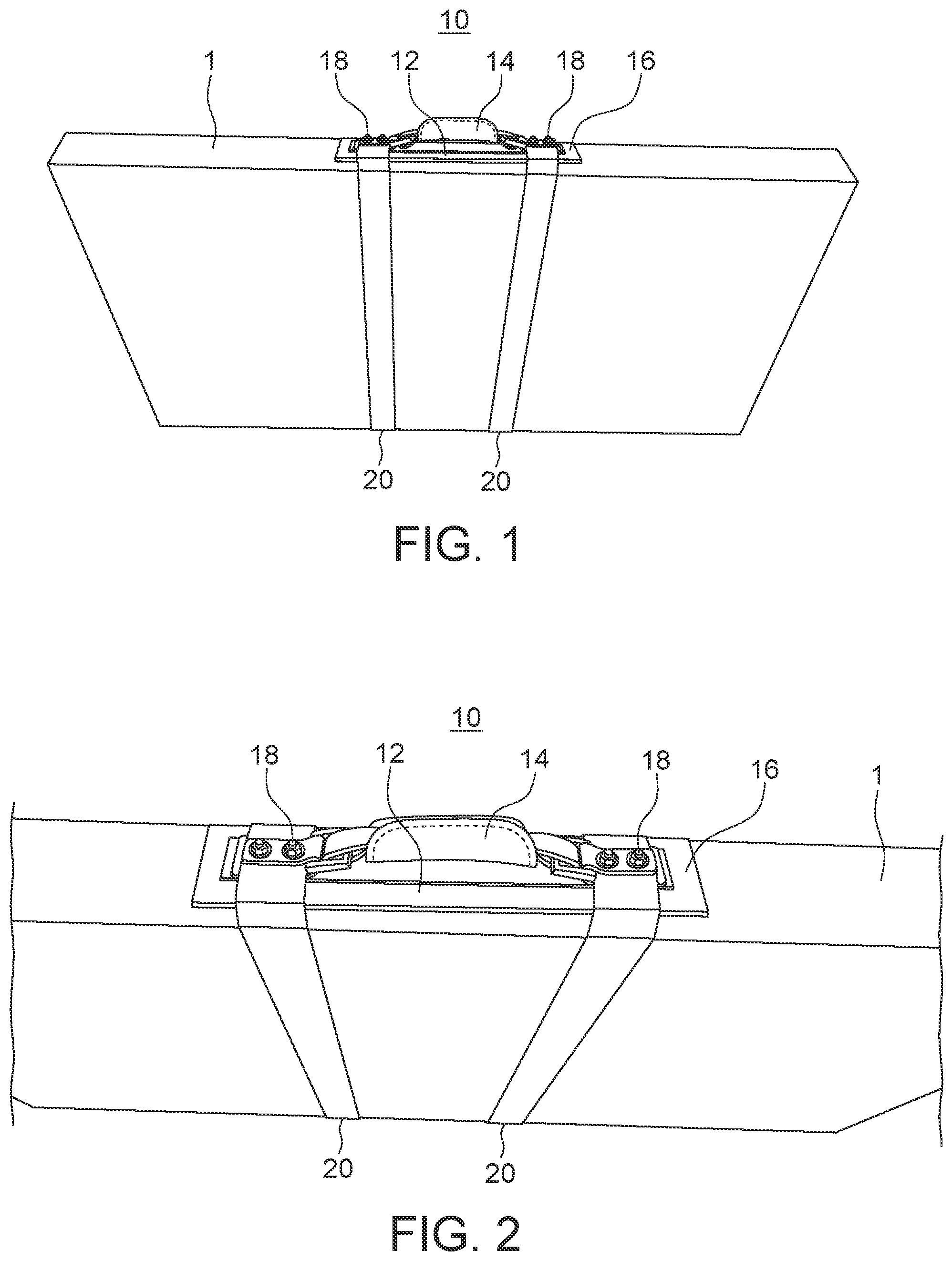
is a side perspective view depicting a first embodiment of a cargo carrying strap system attached to a box.
is a close-up perspective view depicting the cargo carrying strap system of .
is a top perspective view depicting the cargo carrying strap system of .
is a top plan view depicting the cargo carrying strap system of .
is a top plan view depicting a second embodiment of a cargo carrying strap system attached to a box.
is an end perspective view depicting the cargo carrying strap system of .
is a front side elevation view depicting the cargo carrying strap system of .
is a side elevation view depicting a connector strap of the cargo carrying strap system of .
is a rear side elevation view depicting the cargo carrying strap system of .
DETAILED DESCRIPTION OF EMBODIMENTS
In this description, references to “one embodiment”, “an embodiment”, or “embodiments” mean that the feature or features being referred to are included in at least one embodiment of the technology. Separate references to “one embodiment”, “an embodiment”, or “embodiments” in this description do not necessarily refer to the same embodiment and are also not mutually exclusive unless so stated and/or except as will be readily apparent to those skilled in the art from the description. For example, a feature, structure, act, etc. described in one embodiment can also be included in other embodiments but is not necessarily included. Thus, the present technology can include a variety of combinations and/or integrations of the embodiments described herein.
Referring to to 3 , a first embodiment of cargo carrying strap system 10 is shown attached to box 1 . In some embodiments, strap system 10 can comprise of handle assembly 12 fastened to one or more vertical straps 20 with fasteners 18 , wherein straps 20 are disposed around a vertical perimeter of box 1 . In some embodiments, strap assembly 12 can comprise of handle 14 operatively attached to handle base 16 . In some embodiments, handle base 16 can provide rigidity and stability to strap assembly 12 and to strap system 10 . In some embodiments, handle base 16 can be comprised of one or more of cardboard, metal, wood, rigid plastic and other like material as well known to those skilled in the art. In some embodiments, when one vertical strap 20 is used, it will need to be placed near the center of gravity of box 1 so that it is balanced when lifted by strap assembly 12 . In other embodiments, when two vertical straps 20 are used, the two straps 20 can be placed on the outer ends of strap assembly 12 , respectively, near strap connectors 24 that can allow for more stability and security when attached to box 1 .
In the illustrated embodiment, handle 14 and vertical straps 20 can be fastened to handle base 16 with fasteners 18 . While the illustrated embodiment shows fasteners 18 to be threaded nut and bolt fasteners, those skilled in the art would understand that fasteners 18 can comprise one or more of threaded fasteners, rivets, grommets, threaded stitching, adhesives and any other fastening means as well known to those skilled in the art. In some embodiments, handle 14 can be comprised of one or more of fabric, nylon or polyester webbing, leather, rubber, metal or non-metal reinforcement strands and the like as well known to those skilled in the art. In some embodiments, handle 14 can be operatively coupled to strap attachment members 17 with rings or buckles 15 . In some embodiments, each of vertical straps 20 can further comprise strap connector 22 to permit easy wrapping of perimeter straps 20 around box 1 in a vertical direction, and then to fasten the ends of vertical straps 20 together with strap connector 22 . In some embodiments, straps 20 can be comprised of one or more of fabric, nylon or polyester webbing, leather, rubber, metal or non-metal reinforcement strands and the like as well known to those skilled in the art.
In some embodiments, strap connector can comprise of a quick release connector, also known as side release connectors, buckle connectors, bayonet connectors and cam buckles as well known to those skilled in the art. Such connectors can comprise means for quick coupling and uncoupling of the connector ends in addition to including means for tightening the slack of the perimeter strap by pulling the loose end of the strap taut after the connectors ends have been joined together.
Referring to to 9 , a second embodiment of cargo carrying strap system 10 is shown. As shown in , strap assembly 12 can further comprise of additional strap connectors 24 disposed on opposing ends thereof. Referring to , box perimeter strap 26 can be disposed around an edge perimeter of box 1 as shown wherein perimeter strap 26 can couple to strap assembly 12 via strap connectors 24 . Referring to to 9 , in some embodiments, cargo carrying strap system 10 can further comprise of horizontal strap 28 disposed around a horizontal perimeter of box 1 , as shown in these figures. In some embodiments, either or both of straps 26 and 28 can be comprised of one or more of fabric, nylon or polyester webbing, leather, rubber, metal or non-metal reinforcement strands and the like as well known to those skilled in the art.
In some embodiments, strap system 10 can further comprise of connector strap 30 , which can comprise of a single strap comprised of one or more of fabric, nylon or polyester webbing, leather, rubber, metal or non-metal reinforcement strands and the like as well known to those skilled in the art, with each end of connector strap 30 wrapped around one of straps 20 to form loops 34 , with the strap ends then secured to connector strap 30 with fasteners 36 , which can comprise one or more of threaded fasteners, rivets, grommets, threaded stitching, adhesives and the like. Connector strap 30 can further comprise strap connectors 32 disposed on opposing ends thereof to provide means for attaching horizontal strap 28 to. In some embodiments, connector strap 30 can move freely on straps 20 as straps 20 can be inserted through loops 34 before being connected together with strap connectors 22 . Thus, in some embodiments, connector strap 30 and horizontal strap 28 can be implemented on strap system 10 for additional strength and security in enclosing box 1 therewith.
In some embodiments, strap system 10 can use vertical straps 20 , perimeter strap 26 and horizontal strap 28 to encase box 1 on each of its orthogonal axes to provide secure attachment of strap system 10 thereto. By attaching strap system 10 to box 1 in this manner, box 1 can then easily be lifted and carried by grasping handle 14 . After moving box 1 , strap system 10 can then be removed from box 1 by releasing all of the strap connectors.
Although a few embodiments have been shown and described, it will be appreciated by those skilled in the art that various changes and modifications can be made to these embodiments without changing or departing from their scope, intent or functionality. The terms and expressions used in the preceding specification have been used herein as terms of description and not of limitation, and there is no intention in the use of such terms and expressions of excluding equivalents of the features shown and described or portions thereof, it being recognized that the invention is defined and limited only by the claims that follow.
Figures (6)
Citations
This patent cites (55)
- US164994
- US495151
- US799793
- US841620
- US1082017
- US1187496
- US1847501
- US2978154
- US3172586
- US3923222
- US3933287
- US4127223
- US4483380
- US4559906
- US4656566
- US4796936
- US4804218
- US4867359
- US5054816
- US5148956
- US5558382
- US6193293
- US6953214
- US7093324
- USD564761
- US7976088
- US8123236
- USD689284
- US8579345
- US8616600
- US8998052
- US9107489
- USD743628
- USD760653
- US9681738
- US10039368
- US10464727
- US11134770
- US11147361
- USD948871
- US20030222110
- US20060055192
- US20080042460
- US20090057358
- US20090200347
- US20140239656
- US20160100671
- US20170008661
- US20170027308
- US20170055688
- US20180206621
- US20190092571
- US20200297102
- US3017472
- US191105314