Digital Image Sensing Device with Light Intensifier
Abstract
The present disclosure provides a digital image sensing device with a light intensifier, its structure includes a locating handle, a button, a host, a light intensifier, a regulating mechanism and a sensor, wherein the locating handle is connected to the host, the host fits with the light intensifier through the button in a form of electric connection, and the regulating mechanism is arranged between the light intensifier and the sensor; a stopping device and an interweaving device are arranged on a force-assisted body, and mutual fit is performed on a fillet cylinder through the stopping device and the interweaving device; when a guide rail has a closing tendency, a drum bulge inside the guide rail will firstly push the fillet cylinder to roll upwards, the interweaving device is guided to be located on a stabilizer through a pulling sheet.
Claims (8)
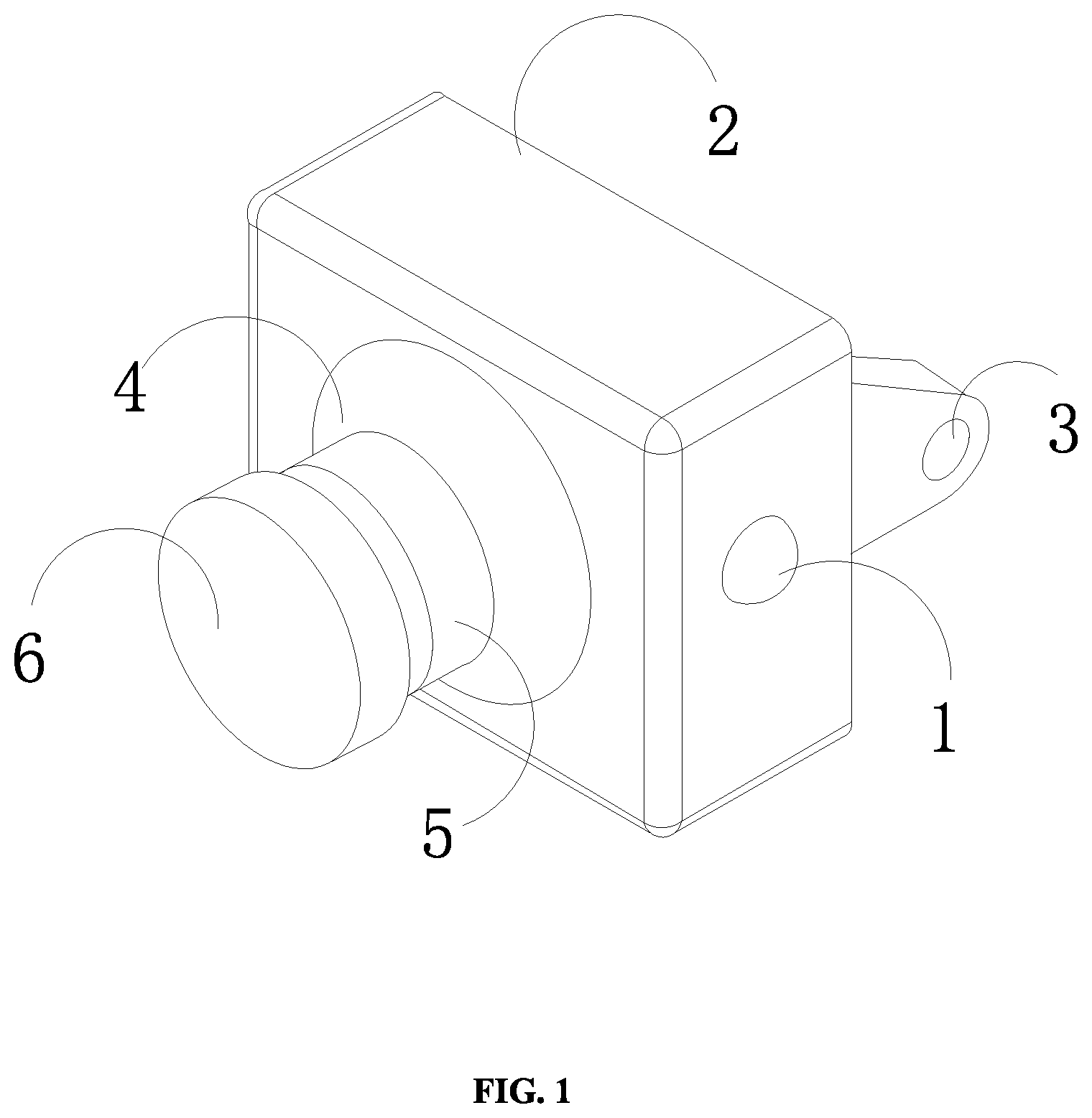
1. A digital image sensing device with a light intensifier, wherein its structure comprises a locating handle ( 3 ), a button ( 1 ), a host ( 2 ), a light intensifier ( 4 ), a regulating mechanism ( 5 ) and a sensor ( 6 ), wherein the locating handle ( 3 ) is connected to the host ( 2 ), the host ( 2 ) fits with the light intensifier ( 4 ) through the button ( 1 ) in a form of electric connection, the regulating mechanism ( 5 ) is arranged between the light intensifier ( 4 ) and the sensor ( 6 ), the regulating mechanism ( 5 ) comprises an opening and closing clip (q 5 ), a drum bulge (w 2 ), a stabilizer (e 1 ), a force-assisted body (r 3 ), a release base (t 4 ) and a guide rail (g 6 ), the opening and closing clip (q 5 ) is connected below the sensor ( 6 ) and in sliding fit with the guide rail (g 6 ), the guide rail (g 6 ) is connected to the release base (t 4 ) through the drum bulge (w 2 ) and provided with the force-assisted body (r 3 ), and the release base (t 4 ) is connected to the light intensifier ( 4 ) through the stabilizer (e 1 ).
Show 7 dependent claims
2. The digital image sensing device with the light intensifier according to claim 1 , wherein the force-assisted body (r 3 ) comprises a pulling sheet (y 34 ), a stopping structure (u 33 ), a fillet cylinder (i 32 ), a shock insulator (o 31 ) and an interweaving device (p 35 ); the pulling sheet (y 34 ) is connected to the fillet cylinder (i 32 ) and in clearance fit with the stabilizer (e 1 ) through the stopping structure (u 33 ); and the fillet cylinder (i 32 ) is installed with the interweaving device (p 35 ) through the shock insulator (o 31 ) and in transition fit with the drum bulge (w 2 ).
3. The digital image sensing device with the light intensifier according to claim 2 , wherein the fillet cylinder (i 32 ) and the shock insulator (o 31 ) are movably clamped between the stabilizer (e 1 ) and the opening and closing clip (q 5 ) through the pulling sheet (y 34 ).
4. The digital image sensing device with the light intensifier according to claim 2 , wherein the stopping structure (u 33 ) comprises a snap ring ( 3 a 3 ), a clamping jaw ( 3 s 2 ), a cross frame ( 3 d 1 ), a filling plate ( 3 f 4 ) and an undertaking member ( 3 h 5 ); and the snap ring ( 3 a 3 ) is connected to the shock insulator (o 31 ) and connected to the clamping jaw ( 3 s 2 ), and the cross frame ( 3 d 1 ) and the filling plate ( 3 f 4 ) are movably clamped in the clamping jaw ( 3 s 2 ) through the undertaking member ( 3 h 5 ).
5. The digital image sensing device with the light intensifier according to claim 4 , wherein the clamping jaw ( 3 s 2 ) is in clearance fit with the shock insulator (o 31 ) and the fillet cylinder (i 32 ) through the cross frame ( 3 d 1 ).
6. The digital image sensing device with the light intensifier according to claim 4 , wherein the undertaking member ( 3 h 5 ) comprises a fillet handrail (j 51 ), a connecting rod (k 54 ), an auxiliary belt ( 152 ), push-together buckles (z 53 ) and a bent handle (x 55 ); the fillet handrail (j 51 ) is connected to the auxiliary belt ( 152 ) through the auxiliary belt ( 152 ) and connected to the push-together buckles (z 53 ), the bent handle (x 55 ) is connected between the push-together buckles (z 53 ), the belt handle (x 55 ) is in clearance fit below the filling plate ( 3 f 4 ), the auxiliary belt ( 152 ) is connected to the connecting rod (k 54 ) through the cross frame ( 3 d 1 ), and the connecting rod (k 54 ) is in sliding fit with the clamping jaw ( 3 s 2 ).
7. The digital image sensing device with the light intensifier according to claim 2 , wherein the interweaving device (p 35 ) comprises a stopper ( 5 c 3 ), a stacked tape ( 5 v 2 ), an isolation mat ( 5 b 1 ) and a folded plate ( 5 n 4 ); and the stopper ( 5 c 3 ) is connected to the fillet cylinder (i 32 ) and movably clamped with the folded plate ( 5 n 4 ) through the stacked tape ( 5 v 2 ); and the folded plate ( 5 n 4 ) is in clearance fit with the stabilizer (e 1 ) and the pulling sheet (y 34 ) through the isolation mat ( 5 b 1 ).
8. The digital image sensing device with the light intensifier according to claim 7 , wherein the isolation mat ( 5 b 1 ) comprises a flat dragging base (w 14 ), a guard plate (e 13 ), a guide pin (r 12 ), a resisting pin (t 11 ) and a passage pole (y 15 ); the flat dragging base (w 14 ) is connected between the stopper ( 5 c 3 ) and the passage pole (y 15 ) and connected to the guide pin (r 12 ); and the guide pin (r 12 ) is in sliding fit with the passage pole (y 15 ), the passage pole (y 15 ) is in rotary fit between the guard plate (e 13 ) and the folded plate ( 5 n 4 ) through the resisting pin (t 11 ), and the guard plate (e 13 ) is in clearance fit with the stabilizer (e 1 ).
Full Description
Show full text →
TECHNICAL FIELD
The present disclosure relates to the technical field of image sensing, in particular to a digital image sensing device with a light intensifier.
BACKGROUND
With the maturity of technology, an image quality of an existing digital camera is getting close to the standard of a traditional camera. At present, the digital camera with millions of pixels has become the mainstream on the market, and the digital camera will replace the market of the traditional camera. A light intensifier may be used to fill light when necessary, thereby improving an image capture effect. The existing digital image sensing device with the light intensifier is usually provided with an inverted-V opening and closing clip, which cooperates with a guide rail to regulate a distance with the light intensifier, and has a certain light-gathering ability, to ensure that its light-emitting scope is the same as the image capture scope of the sensor, thereby increasing the brightness of the image. Since the inclined opening of the guide rail is supported by a drum bulge, when the opening and closing clip slides and clamps an edge of the guide rail, a maximum clamping force will be applied to the guide rail, so that the guide rail has a closing tendency, and the drum bulge inside the guide rail is extruded, resulting in a flat drum bulge and overflowing to an inner wall of the opening and closing clip; and the opening and closing clip is guided secondly to slide upwards, and exceed the light-emitting scope of the light intensifier, so as to reduce the image capture effect after the device is filled with light.
SUMMARY
Aim at the above problem, the present disclosure provides a digital image sensing device with a light intensifier, its structure includes a locating handle, a button, a host, a light intensifier, a regulating mechanism and a sensor, wherein the locating handle is connected to the host, the host fits with the light intensifier through the button in a form of electric connection, the regulating mechanism is arranged between the light intensifier and the sensor, the regulating mechanism includes an opening and closing clip, a drum bulge, a stabilizer, a force-assisted body, a release base and a guide rail, the opening and closing clip is connected below the sensor and in sliding fit with the guide rail, the guide rail is connected to the release base through the drum bulge and provided with the force-assisted body, and the release base is connected to the light intensifier through the stabilizer.
As a further improvement of the present disclosure, the force-assisted body includes a pulling sheet, a stopping structure, a fillet cylinder, a shock insulator and an interweaving device; the pulling sheet is connected to the fillet cylinder and in clearance fit with the stabilizer through the stopping structure; and the fillet cylinder is installed with the interweaving device through the shock insulator and in transition fit with the drum bulge.
As a further improvement of the present disclosure, the fillet cylinder and the shock insulator are clamped between the stabilizer and the opening and closing clip through the pulling sheet, so as to regulate itself rolling angle completely, and with an initial backstop function.
As a further improvement of the present disclosure, the stopping structure includes a snap ring, a clamping jaw, a cross frame, a filling plate and an undertaking member; and the snap ring is connected to the shock insulator and connected to the clamping jaw, and the cross frame and the filling plate are movably clamped in the clamping jaw through the undertaking member.
As a further improvement of the present disclosure, the clamping jaw is in clearance fit with the shock insulator and the fillet cylinder through the cross frame, so as to effectively control the rolling direction of the fillet cylinder.
As a further improvement of the present disclosure, the undertaking member includes a fillet handrail, a connecting rod, an auxiliary belt, push-together buckles and a bent handle; the fillet handrail is connected to the auxiliary belt through the auxiliary belt and connected to the push-together buckles, the bent handle is connected between the push-together buckles, the belt handle is in clearance fit below the filling plate, the auxiliary belt is connected to the connecting rod through the cross frame, and the connecting rod is in sliding fit with the clamping jaw.
As a further improvement of the present disclosure, the interweaving device includes a stopper, a stacked tape, an isolation mat and a folded plate; and the stopper is connected to the fillet cylinder and movably clamped with the folded plate through the stacked tape; and the folded plate is in clearance fit with the stabilizer and the pulling sheet through the isolation mat.
As a further improvement of the present disclosure, the isolation mat includes a flat dragging base, a guard plate, a guide pin, a resisting pin and a passage pole; the flat dragging base is connected between the stopper and the passage pole and connected to the guide pin; and the guide pin is in sliding fit with the passage pole, the passage pole is in rotary fit between the guard plate and the folded plate through the resisting pin, and the guard plate is in clearance fit with the stabilizer.
Beneficial Effects:
Compared with the prior art, the present disclosure has the following beneficial effects:
1. In the present disclosure, the stopping device and the interweaving device are arranged on the force-assisted body, and mutual fit is performed on the fillet cylinder by using the stopping device and the interweaving device; when the guide rail has a closing tendency, the drum bulge inside the guide rail will firstly push the fillet cylinder to roll upwards, the interweaving device is guided to be located on the stabilizer through the pulling sheet, and then the interweaving device is intensively clamped on the stopping structure through the isolation mat in a four-side supporting manner, so that the interweaving device extrudes and rebates on the rolling fillet cylinder, a stop force is formed for the drum bulge, thereby maintaining the stability of the opening and closing clip on the guide rail and ensuring the image capture effect after the device is filled with light.
2. The present disclosure may have deformation and bending of different degrees in a manner that the bent handle is pushed through the push-together buckles and in cooperation with the cross stress of the filling plate and the cross frame, so that the bent handle is convenient to press powerfully at the two sides of the drum bulge, thereby effectively controlling the transverse extension of the drum bulge.
3. In the present disclosure, the guide pin is a bending structure, wherein a protrusion part of the folded plate is adhered to at a bending part, so as to change itself extension degree, further control the rotation direction of the passage pole and strengthen the support of the passage pole to the stopper.
BRIEF DESCRIPTION OF THE DRAWINGS
is a structural schematic diagram of a digital image sensing device with a light intensifier device in the present disclosure.
is a structural schematic diagram of a regulating mechanism in the present disclosure.
is a structural schematic diagram of a force-assisted body in the present disclosure.
is a structural schematic diagram of a stopping structure in the present disclosure.
is a structural schematic diagram of an undertaking member in the present disclosure.
is a structural schematic diagram of an interweaving device in the present disclosure.
is a structural schematic diagram of an isolation mat in the present disclosure.
In the drawings: locating handle- 3 , button- 1 , host- 2 , light intensifier- 4 , regulating mechanism- 5 , sensor- 6 , opening and closing clip-q 5 , drum bulge-w 2 , stabilizer-e 1 , force-assisted body-r 3 , release base-t 4 , guide rail-g 6 , pulling sheet-y 34 , stopping structure-u 33 , fillet cylinder-i 32 , shock insulator-o 31 , interweaving device-p 35 , snap ring- 3 a 3 , clamping jaw- 3 s 2 , cross frame- 3 d 1 , filling plate- 3 f 4 , undertaking member- 3 h 5 , fillet handrail j 51 , connecting rod-k 54 , auxiliary belt- 152 , push-together buckle-z 53 , bent handle-x 55 , stopper- 5 c 3 , stacked tape- 5 v 2 , isolation mat- 5 b 1 , folded plate- 5 n 4 , flat dragging base-w 14 , guard plate-e 13 , guide pin-r 12 , resisting pin-t 11 , passage pole-y 15 .
DETAILED DESCRIPTION OF THE EMBODIMENTS
Based on the embodiments of the present disclosure, all the other embodiments obtained by those of ordinary skill in the art on the premise of not contributing creative effort should belong to the protection scope of the present disclosure.
Embodiment 1
As shown in to , the present disclosure provides a digital image sensing device with a light intensifier, its structure includes a locating handle 3 , a button 1 , a host 2 , a light intensifier 4 , a regulating mechanism 5 and a sensor 6 , wherein the locating handle 3 is welded on the host 2 , the host 2 fits with the light intensifier 4 through the button 1 in a form of electric connection, and the regulating mechanism 5 is arranged between the light intensifier 4 and the sensor 6 ; the regulating mechanism 5 includes an opening and closing clip q 5 , a drum bulge w 2 , a stabilizer e 1 , a force-assisted body r 3 , a release base t 4 and a guide rail g 6 , the opening and closing clip q 5 is fixedly connected below the sensor 6 and in sliding fit with the guide rail g 6 , the guide rail g 6 is in hinge connection with the release base t 4 through the drum bulge w 2 and provided with the force-assisted body r 3 , and the release base t 4 is in embedding connection with the light intensifier 4 through the stabilizer e 1 . The force-assisted body r 3 includes a pulling sheet y 34 , a stopping structure u 33 , a fillet cylinder i 32 , a shock insulator o 31 and an interweaving device p 35 ; the pulling sheet y 34 is in hinge connection with the fillet cylinder i 32 and in clearance fit with the stabilizer e 1 through the stopping structure u 33 ; and the fillet cylinder i 32 is installed with the interweaving device p 35 through the shock insulator o 31 and in transition fit with the drum bulge w 2 . Four fillet cylinders i 32 are provided and movably clamped between the stabilizer e 1 and the opening and closing clip q 5 through the pulling sheet y 34 and the shock insulator o 31 , so as to completely regulate the itself rolling angle and have the initial backstop function. The stopping device u 33 and the interweaving device p 35 are arranged on the force-assisted body r 3 , mutual fit is performed on the fillet cylinder i 32 by using the stopping device u 33 and the interweaving device p 35 ; when the guide rail g 6 has a closing tendency, the drum bulge w 2 inside the guide rail g 6 will firstly push the fillet cylinder i 32 to roll upwards, the interweaving device p 35 is guided to be located on the stabilizer e 1 through the pulling sheet y 34 , and then the interweaving device p 35 is intensively clamped on the stopping structure u 33 through the shock insulator o 31 in a four-side supporting manner, so that the stopping structure u 33 extrudes and rebates on the rolling fillet cylinder i 32 , a stop force is formed for the drum bulge w 2 , thereby maintaining the stability of the opening and closing clip q 5 on the guide rail g 6 and ensuring the image capture effect after the device is filled with light.
Embodiment 2
As shown in to , based on the embodiment 1 and in combination with the mutual fit with the following structure components in the present disclosure, the stopping structure u 33 includes a snap ring 3 a 3 , a clamping jaw 3 s 2 , a cross frame 3 d 1 , a filling plate 3 f 4 and an undertaking member 3 h 5 ; and the snap ring 3 a 3 is in welding connection with a shock insulator o 31 and in hinged connection with the clamping jaw 3 s 2 , the cross frame 3 d 1 and the filling plate 3 f 4 are movably clamped in the clamping jaw 3 s 2 through the undertaking member 3 h 5 , and the clamping jaw 3 s 2 is in clearance fit with the shock insulator o 31 and the fillet cylinder i 32 through the cross frame 3 d 1 , so as to effectively control the rolling direction of the fillet cylinder i 32 . The undertaking member 3 h 5 includes a fillet handrail j 51 , a connecting rod k 54 , an auxiliary belt 152 , push-together buckles z 53 and a bent handle x 55 ; the fillet handrail j 51 is in hinge connection with the auxiliary belt 152 through the auxiliary belt 152 and fixedly connected to the push-together buckles z 53 , the bent handle x 55 is welded between the push-together buckles z 53 , the belt handle x 55 is in clearance fit below the filling plate 3 f 4 , the auxiliary belt 152 is in sleeve connection with the connecting rod k 54 through the cross frame 3 d 1 , and the connecting rod k 54 is in sliding fit with the clamping jaw 3 s 2 . The interweaving device p 35 includes a stopper 5 c 3 , a stacked tape 5 v 2 , an isolation mat 5 b 1 and a folded plate 5 n 4 ; and the stopper 5 c 3 is a triangular structure, in welding connection with the fillet cylinder i 32 and movably clamped with the folded plate 5 n 4 through the stacked tape 5 v 2 ; and the folded plate 5 n 4 is in clearance fit with the stabilizer e 1 and the pulling sheet y 34 through the isolation mat 5 b 1 . The isolation mat 5 b 1 includes a flat dragging base w 14 , a guard plate e 13 , a guide pin r 12 , a resisting pin t 11 and a passage pole y 15 ; the flat dragging base w 14 is in welding connection between the stopper 5 c 3 and the passage pole y 15 and in hinge connection with the guide pin r 12 ; and the guide pin r 12 is in sliding fit with the passage pole y 15 , the passage pole y 15 is in rotary fit between the guard plate e 13 and the folded plate 5 n 4 through the resisting pin t 11 , and the guard plate e 13 is in clearance fit with the stabilizer e 1 . The deformation and bending of different degrees may generate in a manner that the bent handle x 55 is pushed through the push-together buckle z 53 and in cooperation with the cross stress of the filling plate 3 f 4 and the cross frame 3 d 1 , so that the bent handle x 55 is convenient to press powerfully at the two sides of the drum bulge w 2 , thereby effectively controlling the transverse extension of the drum bulge w 2 . The guide pin r 12 is a bending structure, wherein a protrusion part of the folded plate 5 n 4 is adhered to a bending part, so as to change itself extension degree, further control the rotation direction of the passage pole y 15 and strengthen the support of the passage pole y 15 to the stopper 5 c 3 .
The working principle of the digital image sensing device with the light intensifier in the technical solution is described in details below:
During use, when the opening and closing clip q 5 is slidingly clamped to the edge of the guide rail g 6 , the force-assisted body r 3 is arranged on the stabilizer e 1 in order to prevent the closing tendency of the guide rail g 6 and prevent the overflow of the drum bulge w 2 inside the guide rail g 6 . When the guide rail g 6 is further tightened outside the drum bulge w 2 , the guide rail g 6 will firstly contact with the outer side of the fillet cylinder i 32 , so that the fillet cylinder i 32 pulls the shock insulator o 31 to roll inside the opening and closing clip q 5 and drives the pulling sheet y 34 to close to the stabilizer e 1 synchronously, and then the pulling sheet y 34 is opened, and the guide rail g 6 is pressed at the two sides of the folded plate 5 n 4 by the stopper 5 c 3 along the stacked tape 5 v 2 , and the folded plate 5 n 4 pushes the bent part of the guide pin r 12 to arch due to the promotion of the drum bulge w 2 . Taking the flat dragging base w 14 as a support point, a tip is closed and slides on the passage pole y 15 , so that the passage pole y 15 turns out at the two sides of the resisting pin t 11 , and the resisting pin t 11 is driven to push the guard plate e 13 to be resisted on the stabilizer e 1 together, thereby gradually hanging with the tip of the stabilizer e 1 and being folded together. The rolling angle of the fillet cylinder i 32 inside the guide rail g 6 is initially limited, while the fillet cylinder i 32 rolls, the other side will pull the shock insulator o 31 to be stretched together, so that the shock insulator o 31 will be straightened and relax on the snap ring 3 a 3 . The snap ring 3 a 3 is horizontally driven to stretch, so as to change the rolling angle and the opening degree of the clamping jaw 3 s 2 above the snap ring 3 a 3 , control the clamping jaw 3 s 2 to be opened upwards, isolate the limitation of the shock insulator o 31 and pull the cross frame 3 d 1 to deform together. Taking the clamping jaw 3 s 2 as a support point, the filling plate 3 f 4 is clamped and reversely arched to the bent handle x 55 , so that the bent handle x 55 is stressed and adhered to the drum bulge w 2 . When being stabilized, the bent handle x 55 may also reversely support the clamping jaw 3 s 2 to be opened and stretch and climb above the fillet cylinder i 32 , and then the further rolling and stability of the fillet cylinder i 32 are limited. At the same time, in cooperation with the deformation of the cross frame 3 d 1 , the auxiliary belt 152 may be driven to synchronously grab and pull the deflection of the fillet handle j 51 on the connecting rod k 54 , so that the fillet handle j 51 internally rotates and pushes the push-together buckle z 553 and extrudes the two sides of the bent handle x 55 , and then the fillet handle j 51 is in crossed pressing on the drum bulge w 2 in a *-shaped. The deformation direction and itself elasticity of the drum bulge w 2 may be completely regulated and controlled, the stability of the opening and closing clip q 5 on the guide rail g 6 is maintained, the light-gathering ability of the opening and closing clip q 5 on the light intensifier 4 is ensured, and the image capture effect of the sensor 6 is strengthened.
In the description of the present disclosure, it is understood that orientation or position relationships indicated by the terms “center”, “lateral”, “length”, “width”, “height”, “upper”, “lower”, “front”, “rear”, “left”, “right”, “vertical”, “horizontal”, “top”, “bottom”, “inner”, “outer”, “side” and the like are based on the orientation or position relationships as shown in the drawings, for ease of describing the present disclosure and simplifying the description only, rather than indicating or implying that the mentioned apparatus or element necessarily has a particular orientation and must be constructed and operated in the particular orientation. Therefore, these terms should not be understood as limitations to the present disclosure.
Each technical feature of the above embodiments may be combined freely. For simplicity of description, not all possible combinations of each technical solution in the above embodiments are described. However, any combination of these technical features shall fall within the scope recorded in the specification without conflicting.
Figures (7)
Citations
This patent cites (22)
- US6172708
- US7092013
- US7129462
- US7696462
- US7928397
- US8164667
- US8902523
- US10692902
- US10734183
- US11910125
- US20030230707
- US20030231245
- US20090050811
- US20100283877
- US20120069431
- US20120070119
- US20120162489
- US20150350629
- US20160165104
- US20190006400
- US20210335566
- US20220030153