Motor, Motor State Detection Device, and Motor State Determination Device
Abstract
A motor includes a rotor having a rotation shaft, a stator arranged oppositely in a circumferential direction of the rotor, and a pair of bearing portions rotatably supporting the rotation shaft, the pair of bearing portions each include a first bearing being rotatable together with the rotation shaft and a second bearing being rotatable together with the first bearing, the first bearing rotates together with the rotation shaft when the first bearing is normal, and the second bearing as well as the first bearing rotates together with the rotation shaft when the first bearing is abnormal.
Claims (12)
1. A motor comprising: a rotor having a rotation shaft; a stator arranged oppositely in a circumferential direction of the rotor; and a pair of bearing portions rotatably supporting the rotation shaft, wherein the pair of bearing portions each comprise: a first bearing being rotatable together with the rotation shaft; and a second bearing being rotatable together with the first bearing, and the first bearing rotates together with the rotation shaft when the first bearing is normal, and the second bearing as well as the first bearing rotates together with the rotation shaft when the first bearing is abnormal, wherein each bearing portion of the pair of bearing portions comprise a coupling portion coupling the first bearing and the second bearing to rotate in conjunction, and the coupling portions respectively comprised in the pair of bearing portions are coupled to rotate in conjunction.
9. A motor comprising: a rotor having a rotation shaft; a stator arranged oppositely in a circumferential direction of the rotor; and a pair of bearing portions rotatably supporting the rotation shaft, wherein the pair of bearing portions each comprise: a first bearing being rotatable together with the rotation shaft; and a second bearing being rotatable together with the first bearing, and the first bearing rotates together with the rotation shaft when the first bearing is normal, and the second bearing as well as the first bearing rotates together with the rotation shaft when the first bearing is abnormal, wherein the first bearing has a kinetic viscosity lower than a kinetic viscosity of the second bearing.
10. A motor comprising: a rotor having a rotation shaft; a stator arranged oppositely in a circumferential direction of the rotor; and a pair of bearing portions rotatably supporting the rotation shaft, wherein the pair of bearing portions each comprise: a first bearing being rotatable together with the rotation shaft; and a second bearing being rotatable together with the first bearing, and the first bearing rotates together with the rotation shaft when the first bearing is normal, and the second bearing as well as the first bearing rotates together with the rotation shaft when the first bearing is abnormal, further comprising a bearing operation detecting unit detecting operation of the bearing portions, wherein the first bearing comprises a first inner race being rotatable together with the rotation shaft, a first outer race provided on an outer periphery side of the first inner race, and a first rolling element arranged between the first inner race and the first outer race, the second bearing comprises a second inner race being rotatable together with the first outer race, a second outer race provided on an outer periphery side of the second inner race, and a second rolling element arranged between the second inner race and the second outer race, and the bearing operation detecting unit outputs bearing operation information according to rotational operation of the first outer race.
Show 9 dependent claims
2. The motor according to claim 1 , wherein the first bearing comprises a first inner race being rotatable together with the rotation shaft, a first outer race provided on an outer periphery side of the first inner race, and a first rolling element arranged between the first inner race and the first outer race, and the second bearing comprises a second inner race being rotatable together with the first outer race, a second outer race provided on an outer periphery side of the second inner race, and a second rolling element arranged between the second inner race and the second outer race.
3. The motor according to claim 2 , wherein the second bearing is provided at a position distanced from the first bearing in an axial line direction of the rotation shaft.
4. The motor according to claim 2 , wherein the second bearing is provided on an outer periphery side of the first bearing.
5. The motor according to claim 2 , wherein the pair of bearing portions each comprise a coupling portion rotatably coupling the first outer race and the second inner race.
6. The motor according to claim 1 , wherein the first bearing comprises a first inner race being rotatable together with the rotation shaft, a first outer race provided on an outer periphery side of the first inner race, and a first rolling element arranged between the first inner race and the first outer race, the second bearing is provided at a position distanced from the first bearing in an axial line direction of the rotation shaft, and comprises a second inner race being rotatable together with the first outer race, a second outer race provided on an outer periphery side of the second inner race, and a second rolling element arranged between the second inner race and the second outer race, and the coupling portion rotatably couples the first outer race and the second inner race.
7. The motor according to claim 6 , comprising a bearing operation detecting unit detecting operation of at least one of the pair of bearing portions, wherein the bearing operation detecting unit outputs bearing operation information according to rotational operation of the first outer race.
8. The motor according to claim 7 , wherein the bearing operation detecting unit comprises a bearing operation detecting magnet being rotatable together with the first outer race and a bearing operation detecting sensor outputting the bearing operation information according to rotational operation of the bearing operation detecting magnet.
11. The motor according to claim 10 , wherein the bearing operation detecting unit comprises a bearing operation detecting magnet being rotatable together with the first outer race and a bearing operation detecting sensor outputting the bearing operation information according to rotational operation of the bearing operation detecting magnet.
12. The motor according to claim 10 , wherein the second bearing is provided at a position distanced from the first bearing in an axial line direction of the rotation shaft, and the pair of bearing portions each comprise a coupling portion rotatably coupling the first outer race and the second inner race.
Full Description
Show full text →
TECHNICAL FIELD
The present invention relates to a motor, a motor state detection device, and a motor state determination device.
BACKGROUND ART
A cause of failure of a motor is an abnormality such as failure of bearings supporting a rotation shaft attached to a rotor.
In order to appropriately diagnose the presence or absence of a failure sign of the bearings of the motor, it has been known to provide a first temperature sensor for detecting the temperature of a first bearing provided on one end side of a shaft member of an electric motor, a second temperature sensor for detecting the temperature of a second bearing provided on another end side of the shaft member, and a bearing failure sign diagnosing means for diagnosing the presence or absence of a failure sign of the first bearing and the second bearing based on the difference between the temperature of the first bearing and the temperature of the second bearing (see Patent Literature 1).
DOCUMENT LIST
Patent Literature
• Patent Literature 1: Japanese Patent Application Publication No. 2015-231295
SUMMARY OF INVENTION
Technical Problem
When abnormality of a bearing occurs in a motor, there occurs trouble in the rotation of a rotor and thus a need to replace the bearing. In particular, a motor for a cooling fan (hereinafter referred to as a fan motor) for cooling the interior of a server is required to have high reliability because if the fan motor fails, there also occurs trouble in the use of the server. High reliability of a bearing in a fan motor specifically means that the period of time until the occurrence of abnormality of the bearing, that is, the life of the bearing, is long, or that the life of the bearing can be predicted.
However, in the technique of Patent Literature 1, although the life of a bearing can be predicted, increasing the life of the bearing is not considered. In addition, in the technique of Patent Literature 1, since it is necessary to provide the temperature sensors to the two respective bearings, the structure of the motor is complex such as due to the necessity to provide spaces for attachment of the temperature sensors.
The present invention is for the above-described problem as an example, and it is an objective of the present invention to provide a technique that can improve the reliability of a bearing in a motor.
Solution to Problem
In order to achieve the above-mentioned objective, a motor according to the present invention includes: a rotor having a rotation shaft; a stator arranged oppositely in a circumferential direction of the rotor; and a pair of bearing portions rotatably supporting the rotation shaft, wherein the pair of bearing portions each include: a first bearing being rotatable together with the rotation shaft; and a second bearing being rotatable together with the first bearing, and the first bearing rotates together with the rotation shaft when the first bearing is normal, and the second bearing as well as the first bearing rotates together with the rotation shaft when the first bearing is abnormal.
In the motor according to one aspect of the present invention, the first bearing includes a first inner race being rotatable together with the rotation shaft, a first outer race provided on an outer periphery side of the first inner race, and a first rolling element arranged between the first inner race and the first outer race, and the second bearing includes a second inner race being rotatable together with the first outer race, a second outer race provided on an outer periphery side of the second inner race, and a second rolling element arranged between the second inner race and the second outer race.
In the motor according to one aspect of the present invention, the second bearing is provided at a position distanced from the first bearing in an axial line direction of the rotation shaft.
In the motor according to one aspect of the present invention, the second bearing is provided on an outer periphery side of the first bearing.
In the motor according to one aspect of the present invention, the pair of bearing portions each include a coupling portion rotatably coupling the first outer race and the second inner race.
In the motor according to one aspect of the present invention, the first bearing has a kinetic viscosity lower than a kinetic viscosity of the second bearing.
In the motor according to one aspect of the present invention, a bearing operation detecting unit detecting operation of the bearing portions is further included, the first bearing includes a first inner race being rotatable together with the rotation shaft, a first outer race provided on an outer periphery side of the first inner race, and a first rolling element arranged between the first inner race and the first outer race, the second bearing includes a second inner race being rotatable together with the first outer race, a second outer race provided on an outer periphery side of the second inner race, and a second rolling element arranged between the second inner race and the second outer race, and the bearing operation detecting unit outputs bearing operation information according to rotational operation of the first outer race.
In the motor according to one aspect of the present invention, the bearing operation detecting unit includes a bearing operation detecting magnet being rotatable together with the first outer race and a bearing operation detecting sensor outputting the bearing operation information according to rotational operation of the bearing operation detecting magnet.
In the motor according to one aspect of the present invention, a first base plate provided on an outer periphery side of the bearing portions is included, and the bearing operation detecting sensor is mounted to the first base plate.
In the motor according to one aspect of the present invention, the second bearing is provided at a position distanced from the first bearing in an axial line direction of the rotation shaft, and the pair of bearing portions each include a coupling portion rotatably coupling the first outer race and the second inner race.
In the motor according to one aspect of the present invention, the bearing operation detecting unit is provided on an outer periphery side of the coupling portion.
In the motor according to one aspect of the present invention, a second base plate arranged to sandwich the stator with the first base plate in an axial line direction of the rotation shaft, and a rotor operation detecting unit mounted to the second base plate and outputting rotor operation information according to rotational operation of the rotor are included.
In order to achieve the above-mentioned objective, in the motor according to the present invention, the pair of bearing portions each include a coupling portion coupling the first bearing and the second bearing to rotate in conjunction, and the coupling portions respectively included in the pair of bearing portions are coupled to rotate in conjunction.
In the motor according to one aspect of the present invention, the first bearing includes a first inner race being rotatable together with the rotation shaft, a first outer race provided on an outer periphery side of the first inner race, and a first rolling element arranged between the first inner race and the first outer race, the second bearing is provided at a position distanced from the first bearing in an axial line direction of the rotation shaft, and includes a second inner race being rotatable together with the first outer race, a second outer race provided on an outer periphery side of the second inner race, and a second rolling element arranged between the second inner race and the second outer race, and the coupling portion rotatably couples the first outer race and the second inner race.
In the motor according to one aspect of the present invention, a bearing operation detecting unit detecting operation of at least one of the pair of bearing portions is included, and the bearing operation detecting unit outputs bearing operation information according to rotational operation of the first outer race.
In the motor according to one aspect of the present invention, the bearing operation detecting unit includes a bearing operation detecting magnet being rotatable together with the first outer race and a bearing operation detecting sensor outputting the bearing operation information according to rotational operation of the bearing operation detecting magnet.
In the motor according to one aspect of the present invention, the bearing operation detecting sensor is mounted to a base plate provided on an outer periphery side of a bearing portion of the pair of bearing portions provided with the bearing operation detecting unit.
In the motor according to one aspect of the present invention, the bearing operation detecting unit is provided on an outer periphery side of the coupling portion.
In the motor according to one aspect of the present invention, a rotor operation detecting unit outputting rotor operation information according to rotational operation of the rotor is mounted to the base plate.
In order to achieve the above-mentioned objective, a motor state detection device according to the present invention is a device detecting a state of a bearing portion of a motor, the motor includes: a rotor having a rotation shaft; a stator arranged oppositely in a circumferential direction of the rotor; a pair of bearing portions rotatably supporting the rotation shaft and each including a first bearing being rotatable together with the rotation shaft, a second bearing being rotatable together with the first bearing, and a coupling portion coupling the first bearing and the second bearing to rotate in conjunction; a bearing operation detecting unit provided to at least one of the pair of bearing portions and outputting bearing operation information according to rotational operation of the first bearing, and the motor state detection device includes: an information acquiring unit acquiring rotation information, the rotation information being information based on rotational movement of the motor; and a state detecting unit detecting a state of rotational movement of the bearing portions based on the rotation information acquired by the information acquiring unit.
In the motor state detection device according to one aspect of the present invention, the rotation information is information on a rotational frequency of the rotor.
In the motor state detection device according to one aspect of the present invention, the rotation information is information on motor current of the motor.
In the motor state detection device according to one aspect of the present invention, it is determined whether the first bearing or the second bearing is rotating together with the rotation shaft in the bearing portions based on the rotation information.
In order to achieve the above-mentioned objective, a motor state determination device according to the present invention is a state determination device determining a state of a bearing portion of a motor, the motor includes: a first bearing including a first inner race being rotatable together with a rotation shaft of a rotor, a first outer race provided on an outer periphery side of the first inner race, and a first rolling element arranged between the first inner race and the first outer race and rotatably supporting the rotation shaft; a second bearing including a second inner race being rotatable together with the first outer race, a second outer race provided on an outer periphery side of the second inner race, and a second rolling element arranged between the second inner race and the second outer race; and a bearing operation detecting unit outputting bearing operation information according to rotational operation of the first outer race, and the state determination device includes a state determining unit determining a state of rotational movement of the first bearing based on the bearing operation information output by the bearing operation detecting unit.
In the motor state determination device according to one aspect of the present invention, the state determining unit determines whether the first bearing is degraded based on the bearing operation information.
In the motor state determination device according to one aspect of the present invention, the motor includes a rotor operation detecting unit outputting rotor operation information according to rotational operation of the rotor, and the state determining unit determines a state of rotational movement of the first bearing based on the bearing operation information and the rotor operation information.
In the motor state determination device according to one aspect of the present invention, the bearing operation information is information according to a rotational frequency of the first outer race, and the rotor operation information is information according to a rotational frequency of the rotor.
In the motor state determination device according to one aspect of the present invention, the state determining unit determines whether the first bearing is in failure based on information according to a rotational frequency of the first outer race and information according to a rotational frequent rotational frequency of the rotor.
In the motor state determination device according to one aspect of the present invention, a pair of bearing portions each including a coupling portion coupling the first bearing and the second bearing to rotate in conjunction is included, the coupling portion rotatably couples the first outer race and the second inner race, the bearing operation detecting unit is provided to at least one of the pair of bearing portions, and in the state determination device, the state determining unit determines a state of rotational movement of the pair of bearing portions based on the bearing operation information output by the bearing operation detecting unit.
In the motor state determination device according to one aspect of the present invention, the state determination device determines whether at least one of the pair of bearing portions is degraded based on the bearing operation information.
In the motor state determination device according to one aspect of the present invention, the bearing operation detecting unit is provided to one of the pair of bearing portions, and when one of the pair of bearing portions is degraded, it is determined that the first bearing included in either one of the pair of bearing portions is degraded by means of rotational operation of the coupling portion.
In the motor state determination device according to one aspect of the present invention, when the other of the pair of bearing portions is degraded, it is determined that the first bearing included in either one of the pair of bearing portions is degraded by means of rotational operation of the coupling portion.
In the motor state determination device according to one aspect of the present invention, the motor includes a rotor operation detecting unit outputting rotor operation information according to rotational operation of the rotor, and the state determining unit determines the state of rotational movement of the first bearing based on the bearing operation information and the rotor operation information.
In the motor state determination device according to one aspect of the present invention, the bearing operation information is information according to a rotational frequency of the first outer race, and the rotor operation information is information according to a rotational frequency of the rotor.
Effects of Invention
According to the present invention, it is possible to improve the reliability of a bearing in a motor.
BRIEF DESCRIPTION OF DRAWINGS
A front view schematically showing configuration of a fan device including a motor of a first embodiment according to the present invention.
A sectional view schematically showing configuration of the fan device shown in .
A sectional view schematically showing configuration of a rotation shaft and bearing portions included in the fan device shown in .
A flow chart for showing transition of operations of the bearing portions of the motor included in the fan device shown in .
A schematic diagram showing transition of the rotational speed and motor current of the motor included in the fan device shown in .
A functional block diagram of a driving control device of the motor according to the embodiment of the present invention.
A flow chart for showing an example of a state detection process for bearing portions by the driving control device of the motor shown in .
A flow chart for showing a variation of the state detection process for the bearing portions by the driving control device of the motor shown in .
A sectional view schematically showing configuration of a rotation shaft and bearing portions included in a motor according to a second embodiment of the present invention.
A sectional view schematically showing configuration of a fan device including a motor of a third embodiment according to the present invention.
A front view schematically showing configuration of the motor shown in .
A sectional view schematically showing configuration of the motor shown in .
A sectional view schematically showing configuration of a rotation shaft and bearing portions included in the fan device shown in .
A functional block diagram of a driving control device of the motor according to the third embodiment of the present invention.
A flow chart for showing transition of operations of the bearing portions and operations of a bearing operation detecting unit in the motor included in the fan device shown in .
A flow chart for showing an example of a state detection process for the bearing portions by the driving control device of the motor shown in .
A schematic diagram of (a) an FG signal as rotor operation information based on a first Hall signal, (b) a bearing rotational frequency signal as bearing operation information based on a second Hall signal in the state where a first bearing is in normal operation, (c) a bearing rotational frequency signal as bearing operation information based on a second Hall signal in the state where the first bearing is degraded, (d) a bearing rotational frequency signal as bearing operation information based on a second Hall signal in the state where the first bearing is locked up (fails), in the motor included in the fan device shown in .
A sectional view schematically showing configuration of a fan device including a motor of a fourth embodiment according to the present invention.
An exploded perspective view schematically showing configuration of bearing portions included in the fan device shown in .
A sectional view schematically showing configuration of the bearing portions included in the fan device shown in .
A functional block diagram of a driving control device of the motor according to the fourth embodiment of the present invention.
A flow chart for showing transition of operations of the bearing portions and operations of a bearing operation detecting unit when the bearing portion on the lower side is degraded in the motor included in the fan device shown in .
A flow chart for showing transition of operations of the bearing portions and operations of the bearing operation detecting unit when the bearing portion on the upper side is degraded in the motor included in the fan device shown in .
DESCRIPTION OF EMBODIMENTS
Hereinafter, a motor, a motor state detection device, a motor state determination device according to embodiments of the present invention will be described with reference to the drawings.
<First Embodiment of Motor>
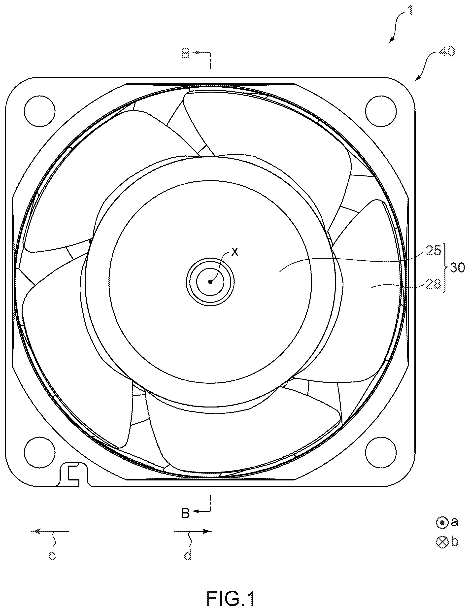
is a front view schematically showing configuration of a fan device 1 including a motor 10 of a first embodiment according to the present invention. is a sectional view schematically showing configuration of the fan device 1 . is a sectional view schematically showing configuration of a rotation shaft 23 and bearing portions 22 included in the fan device 1 .
In the following description, for convenience, it is assumed that the direction of arrow a in the axial line x direction is an upper side a and the direction of arrow b is a lower side b. It is also assumed that a direction away from the axial line x in the radial direction perpendicular to the axial line x (the direction of arrow c in ) is an outer periphery side c and a direction toward the axial line x (the direction of arrow d in ) is an inner periphery side d. In the following description, for convenience, it is assumed that the direction indicated in is toward a side surface of the motor. In the following description, for convenience, it is also assumed that the direction of seeing the motor from the upper side a toward the lower side b is toward a front surface and the direction of seeing the motor from the lower side b toward the upper side a is toward a bottom surface.
As shown in to 3 , the motor 10 according to the present embodiment is provided to the fan device 1 and includes a rotor having the rotation shaft 23 , a stator 24 arranged oppositely in the circumferential direction of the rotor, and a pair of bearing portions 22 A and 22 B rotatably supporting the rotation shaft 23 , the pair of bearing portions 22 A and 22 B each include a first bearing 221 being rotatable together with the rotation shaft 23 and a second bearing 222 being rotatable together with the first bearing 221 , the first bearing 221 rotates together with the rotation shaft 23 when the first bearing 221 is normal, and the second bearing 222 as well as the first bearing 221 rotates together with the rotation shaft 23 when the first bearing 221 is abnormal. Hereinafter, configuration and operation of the fan device 1 including the motor 10 will be specifically described.
[Configuration of Fan Device]
As shown in , the fan device 1 includes an impeller 30 including a plurality of blades 28 at a hub 25 and a casing 40 covering the outer periphery of the impeller 30 and defining the outer shape of the fan device 1 . In the impeller 30 , the hub 25 is arranged at a central portion around the axial line x inside the casing 40 . As shown in , in the fan device 1 , the motor 10 is arranged inside the hub 25 of the impeller 30 .
The motor 10 is, for example, an outer rotor-type brushless DC (Direct Current) motor in which the rotation shaft 23 as well as a rotor yoke 26 and the impeller 30 connected to the rotation shaft 23 form the rotor. The motor 10 includes the rotation shaft 23 , a bearing housing 21 , the pair of bearing portions 22 A and 22 B, the stator 24 , the rotor yoke 26 , and a magnet 27 .
As shown in , the rotation shaft 23 is a rod-shaped member arranged such that the longitudinal direction of the rotation shaft 23 is the axial line x direction. The bearing housing 21 is a hollow cylindrical body supported at a central portion of the casing 40 . The bearing housing 21 rotatably supports the rotation shaft 23 via the pair of bearing portions 22 A and 22 B. The bearing housing 21 includes a bearing supporting portion 212 supporting the bearing portion 22 A at one end of a cylindrical housing body 211 in the axial line x direction and a bearing supporting portion 213 supporting the bearing portion 22 B at another end of the housing body 211 in the axial line x direction. The bearing supporting portions 212 and 213 are each formed on the inner peripheral surface of the housing body 211 .
The pair of bearing portions 22 A and 22 B are specifically the bearing portion 22 A supported by the bearing supporting portion 212 provided at one end of the bearing housing 21 in the axial line x direction and the bearing portion 22 B supported by the bearing supporting portion 213 provided at another end of the bearing housing 21 in the axial line x direction, as described above. The pair of bearing portions 22 A and 22 B each include the first bearing 221 , the second bearing 222 , and a coupling portion 223 . As shown in , in each of the pair of bearing portions 22 A and 22 B, the second bearing 222 is provided at a position distanced from the first bearing 221 in the axial line x direction of the rotation shaft 23 .
The first bearing 221 includes a first inner race 2211 , a first outer race 2212 , and first rolling elements 2213 . The first inner race 2211 is an annular member having an inner peripheral surface that can be fitted to an outer circumferential surface 23 a of the rotation shaft 23 . The first inner race 2211 is rotatable together with the rotation shaft 23 when fitted to the outer circumferential surface 23 a of the rotation shaft 23 . The first outer race 2212 is provided on the outer periphery side c of the first inner race 2211 . The first outer race 2212 is an annular member being coaxial with the first inner race 2211 and having a larger diameter than that of the first inner race 2211 . The first rolling elements 2213 are a plurality of spherical members arranged between the first inner race 2211 and the first outer race 2212 . In the first bearing 221 , lubricant is infused between the first inner race 2211 , the first outer race 2212 , and the first rolling elements 2213 .
The second bearing 222 includes a second inner race 2221 , a second outer race 2222 , and second rolling elements 2223 . The second inner race 2221 is an annular member having an inner peripheral surface that can be fitted to the coupling portion 223 . The second inner race 2221 is rotatable together with the first outer race 2212 via the coupling portion 223 when fitted to the coupling portion 223 . The second outer race 2222 is provided on the outer periphery side c of the second inner race 2221 . The second outer race 2222 is an annular member being coaxial with the second inner race 2221 and having a larger diameter than that of the second inner race 2221 . The second rolling elements 2223 are a plurality of spherical members arranged between the second inner race 2221 and the second outer race 2222 . In the second bearing 222 , lubricant is infused between the second inner race 2221 , the second outer race 2222 , and the second rolling elements 2223 .
The first bearing 221 and the second bearing 222 have different kinetic viscosities from each other such as due to difference in the coefficients of mechanical friction of the components and the viscosities of the lubricants used in the first bearing 221 and the second bearing 222 . In the present embodiment, for example, the first bearing 221 has a kinetic viscosity lower than the kinetic viscosity of the second bearing 222 .
The coupling portion 223 includes a first bearing accommodating part 2231 , a second bearing accommodating part 2232 , and a step portion 2233 . The coupling portion 223 rotatably couples the first outer race 2212 and the second inner race 2221 by the first bearing accommodating part 2231 and the second bearing accommodating part 2232 , which are cylindrical portions having different radial dimensions, and the step portion 2233 connecting the first bearing accommodating part 2231 and the second bearing accommodating part 2232 .
The first bearing accommodating part 2231 has an inner peripheral surface that can accommodate the first outer race 2212 of the first bearing 221 . Specifically, the first bearing accommodating part 2231 is formed to have a shape and dimension that is rotatable in cooperation with the first outer race 2212 .
The second bearing accommodating part 2232 has an inner peripheral surface having a shape and dimension to have a predetermined air gap from the outer circumferential surface 23 a of the rotation shaft 23 . In addition, the second bearing accommodating part 2232 has an outer circumferential surface that can accommodate the second inner race 2221 of the second bearing 222 . The second bearing accommodating part 2232 is formed to have a shape and dimension that is rotatable in cooperation with the second inner race 2221 .
The stator 24 is fixed on the lower side b, for example, of the casing 40 . The stator 24 includes, for example, a stator core 241 formed by laminating a plurality of electromagnetic steel plates, an insulator provided to the stator core 241 , and a coil 242 wound on the stator core 241 via the insulator.
The rotor yoke 26 is provided on the inner periphery portion of the hub 25 of the impeller 30 , for example. The rotor yoke 26 is formed in a generally tubular shape, for example, for accommodating the magnet 27 . The rotor yoke 26 may be formed separately from or integrally with the hub 25 . The magnet 27 is attached to the inner peripheral surface of the rotor yoke 26 . The magnet 27 is provided to have a predetermined gap from the stator 24 provided on the inner periphery side d.
[Operation of Fan Device]
Next, operation of the fan device 1 having the above-described configuration will be described.
is a flow chart for showing transition of operations of the bearing portions 22 A and 22 B of the motor 10 included in the fan device 1 . As shown in , in the motor 10 , rotation of the rotation shaft 23 starts when driving current flows (step S 11 ). As shown in , the rotation shaft 23 of the motor 10 is rotatably supported by the pair of bearing portions 22 A and 22 B fitted to the bearing housing 21 . In addition, one end of the rotation shaft 23 on the upper side a is coupled to the hub 25 of the impeller 30 . Thus, when the motor 10 is driven, the rotation shaft 23 rotates about the axial line x, and the impeller 30 also rotates about the axial line x in association.
Here, in the motor 10 , the pair of bearing portions 22 A and 22 B each include the first bearing 221 being rotatable together with the rotation shaft 23 and the second bearing 222 being rotatable together with the first bearing 221 . Here, in the pair of bearing portions 22 A and 22 B, the kinetic viscosity of the first bearing 221 and the kinetic viscosity of the second bearing 222 are different. That is, in the motor 10 , one of the first bearing 221 and the second bearing 222 that has a lower kinetic viscosity (for example, the first bearing 221 ) rotates more easily due to the difference in kinetic viscosity between the two bearings (the first bearing 221 and the second bearing 222 ) included in each of the pair of bearing portions 22 A and 22 B. In the bearing portions 22 A and 22 B of the motor 10 configured in this manner, in a regular state (during a predetermined time after starting operation), the first bearing 221 having a lower kinetic viscosity has a normal operational function, and thus the first inner race 2211 is supported by the first rolling elements 2213 and the first outer race 2212 and rotates together with the rotation shaft 23 . Such a state where the first inner race 2211 is supported by the first rolling elements 2213 and the first outer race 2212 and rotates together with the rotation shaft 23 in the first bearing 221 is referred to as a normal state.
Thereafter, in the bearing portions 22 A and 22 B in the motor 10 , when the operational function of the first bearing 221 is degraded or starts to fail, the coefficient of friction of the first bearing 221 rises (step S 12 ). Such a state where degradation or failure of the operational function of the first bearing 221 occurs to cause abnormality and the coefficient of friction rises is referred to as an abnormal state. In the bearing portions 22 A and 22 B, when the rotational torque of the first bearing 221 exceeds a starting torque of the second bearing 222 , the coupling portion 223 and the second bearing 222 start to rotate (step S 13 ). Specifically, in the bearing portions 22 A and 22 B, the first inner race 2211 , the first outer race 2212 , and the first rolling elements 2213 of the first bearing 221 integrally rotate together with the rotation shaft 23 . In the coupling portion 223 , the inner peripheral surface of the first bearing accommodating part 2231 is connected to be rotatable together with the first outer race 2212 of the first bearing 221 . In such a state where the first outer race 2212 rotates together with the first inner race 2211 in the first bearing 221 , the second bearing 222 starts rotation (co-rotation) together with the rotation shaft 23 via the coupling portion 223 (step S 14 ). That is, the second inner race 2221 of the second bearing 222 is attached to the outer circumferential surface of the second bearing accommodating part 2232 of the coupling portion 223 and thus can rotate in association with the rotation of the coupling portion 223 . Thus, in the motor 10 , the coupling portion 223 and the second bearing 222 rotate together with the rotation shaft 23 (step S 15 ).
With the motor 10 configured as described above and the fan device 1 including the motor 10 , since the rotation shaft 23 is supported by the pair of bearing portions 22 A and 22 B including the first bearing 221 and the second bearing 222 having different kinetic viscosities, it is possible to continue operation without replacing bearing components even when the first bearing 221 is in an abnormal state such as degradation or failure. That is, with the motor 10 configured as described above and the fan device 1 including the motor 10 , it is possible to increase the life of the bearings even in an application in which constant operation is performed and timing for maintenance such as component replacement is limited, such as a cooling fan for a server, for example.
is a schematic diagram showing transition of the rotational speed and motor current of the motor 10 included in the fan device 1 . shows change in the values of the rotational speed and motor current of the motor 10 in association with degradation of the bearing portions 22 A and 22 B from the start of the operation of the motor 10 . In , there are shown t0: the time of start of the operation of the motor 10 , t1: the time at which the first bearing 221 is no longer in a normal operational state (start of failure of the first bearing 221 ), and t2: the time at which the first bearing 221 together with the coupling portion 223 starts to rotate integrally with the rotation shaft 23 (co-rotation of the inner and outer races of the first bearing 221 ). As shown in , in the period of time from t0 to t1, the motor 10 is operated with a rotational speed of R2 and a motor current value of A1 since the first bearing 221 is in normal operation. However, in the period of time until t2 after t1, in the motor 10 , the first bearing 221 is degraded and the rotational torque of the first bearing 221 gradually increases, and thus the rotational speed decreases from R2 and the motor current value rises from A1. After t2, when the rotational torque of the first bearing 221 exceeds the starting torque of the second bearing 222 , the second bearing 222 operates in the bearing portions 22 A and 22 B, and thus the rotational speed becomes R1 and the motor current value becomes A2.
With the motor 10 and the fan device 1 including the motor 10 configured as described above, since the rotation shaft 23 is supported by the pair of bearing portions 22 A and 22 B including the first bearing 221 and the second bearing 222 having different kinetic viscosities, it is possible to easily recognize which of the first bearing 221 or the second bearing 222 is operating in the bearing portions 22 A and 22 B by measuring the rotational speed and motor current of the motor 10 , for example. That is, with the motor 10 configured as described above and the fan device 1 including the motor 10 , it is possible to easily recognize the operational state of the bearing portions 22 A and 22 B and thus predict the replacement timing and life of the bearing portions 22 A and 22 B.
Therefore, with the motor 10 configured as described above and the fan device 1 including the motor 10 , it is possible to improve the reliability of the bearings.
In addition, with the motor 10 and the fan device 1 including the motor 10 , it is possible to transmit the rotation of the rotation shaft 23 to the second bearing 222 by means of the coupling portion 223 when the first bearing 221 is degraded, and thus improve the reliability of the bearings. In addition, since the coupling portion 223 does not transmit the rotation to the second bearing 222 when the first bearing 221 is in normal operation, it is possible to improve the reliability of the bearings without causing loss in the bearing portions 22 A and 22 B.
<Motor State Detection Device of First Embodiment>
Next, a motor state detection device of the first embodiment will be described.
In the present embodiment, a driving control device 3 of the motor 10 functions as a state detection device that detects the state of the bearing portions 22 A and 22 B of the motor 10 . The driving control device 3 includes a rotational frequency calculating unit 32 as an information acquiring unit that acquires rotation information, which is information based on rotational movement of the motor 10 , and a bearing abnormality determining unit 35 as a state detecting unit that detects the state of rotational movement of the bearing portions 22 A and 22 B based on the rotation information acquired by the rotational frequency calculating unit 32 . Hereinafter, the driving control device 3 of the motor 10 functioning as a motor state detection device will be described.
is a functional block diagram of the driving control device 3 of the motor 10 according to the embodiment of the present invention. As shown in , the driving control device 3 of the motor 10 includes a speed command analyzing unit 31 , the rotational frequency calculating unit 32 , a PWM (Pulse Width Modulation) command unit 33 , a PWM signal generating unit 34 , and the bearing abnormality determining unit 35 . The driving control device 3 is realized by, for example, an information processing device capable of executing various computer programs including a program for realizing the following functional blocks of the driving control device 3 according to the present invention, such as an MCU (Micro Controller Unit), and a storage device such as a ROM (Read-Only Memory) for storing the computer programs, data for executing the programs, and the like. The ROM also stores information on predetermined values for the rotation information used for the processing of the bearing abnormality determining unit 35 , which will be described later.
The speed command analyzing unit 31 receives a speed command signal Sc for the motor 10 from external equipment (not shown) such as a control unit of a server, and generates a target rotational frequency signal S 1 for providing an indication to the PWM command unit 33 .
The rotational frequency calculating unit 32 acquires a first Hall signal Sh 1 (information on a rotational frequency) acquired by a Hall sensor H 1 attached to the motor 10 and provided to detect the rotational frequency of the rotor (the rotation shaft 23 or the impeller 30 ) as actual rotation information of the rotor, and calculates the rotational frequency of the rotor. The rotational frequency calculating unit 32 outputs a rotational frequency signal S 2 to the PWM command unit 33 and the bearing abnormality determining unit 35 . In addition, the rotational frequency calculating unit 32 outputs the calculated rotational frequency of the rotor to the external equipment as an FG (Frequency Generator) signal.
The PWM command unit 33 outputs, to the PWM signal generating unit 34 , a PWM setting indication signal S 3 generated based on the target rotational frequency signal S 1 output from the speed command analyzing unit 31 and the rotational frequency signal S 2 output from the rotational frequency calculating unit 32 . The PWM setting indication signal S 3 is a signal indicating setting of a PWM signal to be generated by the PWM signal generating unit 34 , that is, the duty cycle of a PWM signal required to drive the motor 10 at a desired rotational frequency.
The PWM signal generating unit 34 generates and outputs a driving control signal Sd for controlling a motor driving unit 2 , that is, a PWM signal S 4 having a desired duty cycle based on the PWM setting indication signal S 3 output by the PWM command unit 33 .
The motor driving unit 2 drives the motor 10 based on the driving control signal Sd. In addition, the bearing abnormality determining unit 35 acquires a current signal S 5 , which is information on the motor current flowing in the motor driving unit 2 as an example of rotation information of the motor.
The bearing abnormality determining unit 35 functions as an information acquiring unit that acquires rotation information, which is information based on rotational movement of the motor 10 , and a state detecting unit that detects the state of rotational movement of the bearing portions 22 A and 22 B based on the rotation information acquired by the information acquiring unit. Specifically, the bearing abnormality determining unit 35 determines whether the first bearing 221 or the second bearing 222 is rotating together with the rotation shaft 23 in the bearing portions 22 A and 22 B based on at least one of the rotational frequency signal S 2 and the current signal S 5 , which are the rotation information, and detects whether an abnormal state such as degradation or failure of the first bearing 221 of the bearing portions 22 A and 22 B is occurring. When detecting abnormality of the bearing portions 22 A and 22 B, the bearing abnormality determining unit 35 outputs information indicating the abnormal state of the bearing portions 22 A and 22 B to the external equipment as an abnormality reporting signal Sa.
is a flow chart for showing an example of a state detection process for the bearing portions 22 A and 22 B by the driving control device 3 of the motor 10 . In the example of the state detection process for the bearing portions 22 A and 22 B by the driving control device 3 shown in , the bearing abnormality determining unit 35 detects the state of the bearing portions 22 A and 22 B based on the rotational frequency signal S 2 , which is information on the rotational frequency of the motor, and the current signal S 5 , which is information on the motor current flowing in the motor driving unit 2 , as the rotation information. As shown in , in the driving control device 3 , the bearing abnormality determining unit 35 determines whether the rotational frequency of the motor is greater than or equal to a predetermined value, for example, R1 shown in , based on the rotational frequency signal S 2 output by the rotational frequency calculating unit 32 (S 101 ).
If the rotational frequency of the motor is less than or equal to the predetermined value (step S 101 : NO), the bearing abnormality determining unit 35 determines whether the motor current flowing in the motor 10 is less than a predetermined value, for example, A2 shown in , based on the current signal S 5 , which is information on the motor current flowing in the motor driving unit 2 (step S 102 ).
If the motor current flowing in the motor 10 exceeds the predetermined value (step S 102 : NO), the bearing abnormality determining unit 35 determines that the first bearing 221 of the bearing portions 22 A and 22 B is in an abnormal state of being degraded (step S 103 ). As shown in , when the first bearing 221 is degraded, the rotational torque of the first bearing 221 gradually increases, and thus the rotational speed decreases from the normal state and the motor current also rises from the normal state. Thus, the bearing abnormality determining unit 35 can detect that both of the rotational speed and motor current of the motor 10 are changed from the normal numerical values to detect the abnormal state, that is, life of the bearing portions 22 A and 22 B.
On the other hand, if the rotational frequency of the motor 10 is greater than or equal to the predetermined value (step S 101 : YES) or the motor current of the motor 10 is less than the predetermined value (step S 102 : YES), the bearing abnormality determining unit 35 determines that the first bearing 221 of the bearing portions 22 A and 22 B is in normal operation (step S 104 ).
is a flow chart for showing a variation of the state detection process for the bearing portions 22 A and 22 B by the driving control device 3 of the motor 10 . In the variation of the state detection process for the bearing portions 22 A and 22 B by the driving control device 3 shown in , the bearing abnormality determining unit 35 detects the state of the bearing portions 22 A and 22 B based on either information of the rotational frequency signal S 2 , which is information on the rotational frequency of the motor, or the current signal S 5 , which is information on the motor current flowing in the motor driving unit 2 , as the rotation information. As shown in , in the driving control device 3 , the bearing abnormality determining unit 35 determines whether the rotational frequency of the motor is greater than or equal to a predetermined value, for example, R1 shown in , based on the rotational frequency signal S 2 output by the rotational frequency calculating unit 32 (step S 201 ).
If the rotational frequency of the motor 10 is greater than or equal to the predetermined value (step S 201 : YES), the bearing abnormality determining unit 35 determines whether the motor current flowing in the motor 10 is less than a predetermined value, for example, A2 shown in , based on the current signal S 5 , which is information on the motor current flowing in the motor driving unit 2 (step S 202 ).
If the rotational frequency of the motor 10 is less than or equal to the predetermined value (step S 201 : NO) or the motor current flowing in the motor 10 exceeds the predetermined value (step S 202 : NO), the bearing abnormality determining unit 35 determines that the first bearing 221 of the bearing portions 22 A and 22 B is in an abnormal state of being degraded (S 203 ). In the variation, in a manner similar to the example previously described, the bearing abnormality determining unit 35 can detect that both of the rotational speed and motor current of the motor 10 are changed from the normal values to detect the abnormal state, that is, life of the bearing portions 22 A and 22 B.
On the other hand, if the motor current of the motor 10 is less than the predetermined value (step S 202 : YES), the bearing abnormality determining unit 35 determines that the first bearing 221 of the bearing portions 22 A and 22 B is in normal operation (step S 204 ).
With the driving control device 3 of the motor 10 configured as described above, since the operational state of the bearing portions 22 A and 22 B is determined based on the rotation information of the motor 10 in which the rotation shaft 23 is supported by the pair of bearing portions 22 A and 22 B including the first bearing 221 and the second bearing 222 having different kinetic viscosities, for example, the rotation information obtained by measuring at least one of the rotational speed and motor current of the motor 10 , it is possible to easily determine which of the first bearing 221 or the second bearing 222 is operating in the bearing portions 22 A and 22 B, that is, the operational state of the bearing portions 22 A and 22 B. That is, with the driving control device 3 of the motor 10 configured as described above, it is possible to easily determine the operational state of the bearing portions 22 A and 22 B of the motor 10 and thus predict the replacement timing and life of the bearing portions 22 A and 22 B.
Therefore, with the driving control device 3 of the motor 10 configured as described above, it is possible to improve the reliability of the bearings.
<Second Embodiment of Motor>
Next, a second embodiment of a motor according to the present invention will be described. Note that components of the motor according to the present embodiment similar to those of the motor 10 previously described are given by the same reference characters, and descriptions of these components will be omitted.
is a sectional view schematically showing configuration of the rotation shaft 23 and bearing portions 22 Ab and 22 Bb included in the motor according to the second embodiment of the present invention.
As shown in , in the pair of bearing portions 22 Ab and 22 Bb included in the motor according to the second embodiment, in a manner similar to the pair of bearing portions 22 A and 22 B previously described, the bearing portion 22 Ab is supported by a bearing supporting portion 212 b provided at one end of a bearing housing 21 b in the axial line x direction, and the bearing portion 22 Bb is supported by a bearing supporting portion 213 b provided at another end of the bearing housing 21 b in the axial line x direction.
The pair of bearing portions 22 Ab and 22 Bb included in the motor according to the second embodiment are different from the pair of bearing portions 22 A and 22 B previously described in that a first bearing 221 b and a second bearing 222 b of the bearing portions 22 Ab and 22 Bb are arranged at positions along a direction perpendicular to the axial line x direction of the rotation shaft 23 . That is, in the pair of bearing portions 22 Ab and 22 Bb, the second bearing 222 b is provided on the radially outer side of the first bearing 221 b , that is, on the outer periphery side c of the first bearing 221 b . Since the first bearing 221 b and the second bearing 222 b are arranged in the above-described manner, the pair of bearing portions 22 Ab and 22 Bb are different from the pair of bearing portions 22 A and 22 B previously described in that a first outer race 2212 b of the first bearing 221 b and a second inner race 2221 b of the second bearing 222 b contact each other. Also, the pair of bearing portions 22 Ab and 22 Bb are different from the pair of bearing portions 22 A and 22 B previously described in that there is no coupling portion 223 connecting the first outer race 2212 and the second inner race 2221 since the first outer race 2212 b of the first bearing 221 b and the second inner race 2221 b of the second bearing 222 b contact each other and are configured to be rotatable together.
With the motor and the fan device including the bearing portions 22 Ab and 22 Bb configured as described above, since the rotation shaft 23 is supported by the pair of bearing portions 22 Ab and 22 Bb including the first bearing 221 b and the second bearing 222 b having different kinetic viscosities, it is possible to continue operation without replacing bearing components even when the first bearing 221 b is degraded or fails. That is, with the motor and the fan device including the bearing portions 22 Ab and 22 Bb configured as described above, it is possible to increase the life of the bearings even in an application in which constant operation is performed and timing for maintenance such as component replacement is limited, such as a cooling fan for a server, for example.
Therefore, with the motor and the fan device including the bearing portions 22 A and 22 B configured as described above, it is possible to improve the reliability of the bearings.
<Third Embodiment of Motor>
Next, a fan device 1 C including a motor 10 C of a third embodiment according to the present invention will be described. Note that components of the motor 10 C according to the present embodiment similar to those of the motor 10 previously described are given by the same reference characters, and descriptions of these components will be omitted.
is a sectional view schematically showing configuration of the fan device 1 C. is a front view schematically showing configuration of the motor 10 C. is a sectional view schematically showing configuration of the motor 10 C. is a sectional view schematically showing configuration of a rotation shaft 23 C and bearing portions 22 AC and 22 BC included in the fan device 1 C.
As shown in to 13 , the motor 10 C according to the present embodiment is provided to the fan device 1 C and includes a rotor having a rotation shaft 23 C, a stator 24 C arranged oppositely in the circumferential direction of the rotor, a pair of bearing portions 22 AC and 22 BC rotatably supporting the rotation shaft 23 C and including a first bearing 221 C being rotatable together with the rotation shaft 23 C and a second bearing 222 C being rotatable together with the first bearing 221 C, and a bearing operation detecting unit 37 for detecting operation of the bearing portion 22 AC and 22 BC, the first bearing 221 C includes a first inner race 2211 C being rotatable together with the rotation shaft 23 C, a first outer race 2212 C provided on the outer periphery side c of the first inner race 2211 C, and first rolling elements 2213 C arranged between the first inner race 2211 C and the first outer race 2212 C, the second bearing 222 C includes a second inner race 2221 C being rotatable together with the first outer race 2212 C, a second outer race 2222 C provided on the outer periphery side of the second inner race 2221 C, and second rolling elements 2223 C arranged between the second inner race 2221 C and the second outer race 2222 C, and the bearing operation detecting unit 37 outputs bearing operation information according to rotational operation of the first outer race 2212 C. Hereinafter, configuration and operation of the fan device 1 C including the motor 10 C will be specifically described.
[Configuration of Fan Device]
As shown in , the fan device 1 C includes an impeller 30 C including a plurality of blades 28 C at a hub 25 C and a casing 40 C covering the outer periphery of the impeller 30 C and defining the outer shape of the fan device 1 C. In the impeller 30 C, the hub 25 C is arranged at a central portion around the axial line x inside the casing 40 C. As shown in , in the fan device 1 C, the motor 10 C is arranged inside the hub 25 C of the impeller 30 C.
As shown in , the motor 10 C is, for example, an outer rotor-type brushless DC (Direct Current) motor in which the rotation shaft 23 C, a rotor yoke 26 C connected to the rotation shaft 23 C, and the impeller 30 C form the rotor. The motor 10 C includes the rotation shaft 23 C, a bearing housing 21 C, the pair of bearing portions 22 AC and 22 BC, the stator 24 C, the rotor yoke 26 C, a magnet 27 C, a first base plate 291 C, a second base plate 292 C, a rotor operation detecting sensor (an example of a rotor operation detecting unit) 36 C, and the bearing operation detecting unit 37 .
As shown in , 12 , and 13 , the rotation shaft 23 C is a rod-shaped member arranged such that the longitudinal direction of the rotation shaft 23 C is the axial line x direction. The bearing housing 21 C is a hollow cylindrical body supported at a central portion of the casing 40 C. The bearing housing 21 C rotatably supports the rotation shaft 23 C via the pair of bearing portions 22 AC and 22 BC. The bearing housing 21 C includes a bearing supporting portion 212 C supporting the bearing portion 22 AC at one end of a cylindrical housing body 211 C in the axial line x direction and a bearing supporting portion 213 C supporting the bearing portion 22 BC at another end of the housing body 211 C in the axial line x direction. The bearing supporting portions 212 C and 213 C are each formed on the inner peripheral surface of the housing body 211 C.
The pair of bearing portions 22 AC and 22 BC are specifically the bearing portion 22 AC supported by the bearing supporting portion 212 C provided at one end of the bearing housing 21 C in the axial line x direction and the bearing portion 22 BC supported by the bearing supporting portion 213 C provided at another end of the bearing housing 21 C in the axial line x direction, as described above. The pair of bearing portions 22 AC and 22 BC each include the first bearing 221 C, the second bearing 222 C, and a coupling portion 223 C. As shown in , in each of the pair of bearing portions 22 AC and 22 BC, the second bearing 222 C is provided at a position distanced from the first bearing 221 C in the axial line x direction of the rotation shaft 23 C.
As shown in , the first bearing 221 C includes the first inner race 2211 C, the first outer race 2212 C, and the first rolling elements 2213 C. The first inner race 2211 C is an annular member having an inner peripheral surface that can be fitted to an outer circumferential surface 23 a of the rotation shaft 23 C. The first inner race 2211 C is rotatable together with the rotation shaft 23 C when fitted to the outer circumferential surface 23 a of the rotation shaft 23 C. The first outer race 2212 C is provided on the outer periphery side c of the first inner race 2211 C. The first outer race 2212 C is an annular member being coaxial with the first inner race 2211 C and having a larger diameter than that of the first inner race 2211 C. The first rolling elements 2213 C are a plurality of spherical members arranged between the first inner race 2211 C and the first outer race 2212 C. In the first bearing 221 C, lubricant is infused between the first inner race 2211 C, the first outer race 2212 C, and the first rolling elements 2213 C.
The second bearing 222 C includes the second inner race 2221 C, the second outer race 2222 C, and the second rolling elements 2223 C. The second inner race 2221 C is an annular member having an inner peripheral surface that can be fitted to the coupling portion 223 C. The second inner race 2221 C is rotatable together with the first outer race 2212 C via the coupling portion 223 C when fitted to the coupling portion 223 C. The second outer race 2222 C is provided on the outer periphery side c of the second inner race 2221 C. The second outer race 2222 C is an annular member being coaxial with the second inner race 2221 C and having a larger diameter than that of the second inner race 2221 C. The second rolling elements 2223 C are a plurality of spherical members arranged between the second inner race 2221 C and the second outer race 2222 C. In the second bearing 222 C, lubricant is infused between the second inner race 2221 C, the second outer race 2222 C, and the second rolling elements 2223 C.
The first bearing 221 C and the second bearing 222 C may have different kinetic viscosities from each other such as due to difference in the coefficients of mechanical friction of the components and the viscosities of the lubricants used in the first bearing 221 C and the second bearing 222 C. In the present embodiment, for example, the first bearing 221 C has a kinetic viscosity lower than the kinetic viscosity of the second bearing 222 C. Note that the kinetic viscosity of the first bearing 221 C may be the same as the kinetic viscosity of the second bearing 222 C or higher than the kinetic viscosity of the second bearing 222 C.
The coupling portion 223 C includes a first bearing accommodating part 2231 C, a second bearing accommodating part 2232 C, and a step portion 2233 C. The coupling portion 223 C rotatably couples the first outer race 2212 C and the second inner race 2221 C by the first bearing accommodating part 2231 C and the second bearing accommodating part 2232 C, which are cylindrical portions having different radial dimensions, and the step portion 2233 C connecting the first bearing accommodating part 2231 C and the second bearing accommodating part 2232 C.
The first bearing accommodating part 2231 C has an inner peripheral surface that can accommodate the first outer race 2212 C of the first bearing 221 C. Specifically, the first bearing accommodating part 2231 C is formed to have a shape and dimension that is rotatable in cooperation with the first outer race 2212 C.
The second bearing accommodating part 2232 C has an inner peripheral surface having a shape and dimension to have a predetermined air gap from the outer circumferential surface 23 a of the rotation shaft 23 C. In addition, the second bearing accommodating part 2232 C has an outer circumferential surface that can accommodate the second inner race 2221 C of the second bearing 222 C. The second bearing accommodating part 2232 C is formed to have a shape and dimension that is rotatable in cooperation with the second inner race 2221 C.
The stator 24 C is fixed on the lower side b, for example, of the casing 40 C. The stator 24 C includes, for example, a stator core 241 C formed by laminating a plurality of electromagnetic steel plates, a coil 242 C wound on the stator core 241 C, and an insulator 243 C provided to the stator core 241 C.
The rotor yoke 26 C is provided on the inner periphery portion of the hub 25 C of the impeller 30 C, for example. The rotor yoke 26 C is formed in a generally tubular shape, for example, for accommodating the magnet 27 C. The rotor yoke 26 C may be formed separately from or integrally with the hub 25 C. The magnet 27 C is attached to the inner peripheral surface of the rotor yoke 26 C. The magnet 27 C is provided to have a predetermined gap from the stator 24 C provided on the inner periphery side d.
As shown in , the first base plate 291 C is provided on the outer periphery side c of at least one of the bearing portions 22 AC and 22 BC, for example, the bearing portion 22 AC on the upper side a at one end of the stator 24 C in the axial line x direction. As shown in , the first base plate 291 C is a plate-shaped base plate formed in a substantially arc shape at a portion on the outer periphery side c of the bearing portion 22 AC. A bearing operation detecting sensor 372 of the bearing operation detecting unit 37 is mounted on the upper side a of the first base plate 291 C.
As shown in , the second base plate 292 C is provided on the outer periphery side c of at least the other of the bearing portions 22 AC and 22 BC, for example, the bearing portion 22 BC on the lower side b at another end of the stator 24 C in the axial line x direction. That is, the second base plate 292 C is arranged to sandwich the stator 24 C with the first base plate 291 C in a direction parallel to the axial line x of the rotation shaft 23 C of the rotor. As shown in , the second base plate 292 C is a base plate formed such that its outer shape is a substantially disc shape on the outer periphery side c of the bearing portion 22 BC. A rotor operation detecting sensor 36 C as a rotor operation detecting unit is mounted on the upper side a of the second base plate 292 C.
The rotor operation detecting sensor 36 C is mounted on the upper side a of the second base plate 292 C as described above. The rotor operation detecting sensor 36 C is arranged in the magnetic field range of the magnet 27 C provided on the inner peripheral surface of the hub 25 C of the impeller 30 C forming the rotor, for example, on the inner periphery side d of the magnet 27 C. As the magnet 27 C attached to the rotor rotates, the rotor operation detecting sensor 36 C outputs a first Hall signal (an example of rotor operation information) as rotor operation information, which is a positional signal according to rotational operation of the magnet 27 C. The rotor operation information is, specifically, for example, information according to the rotational frequency of the rotor such as information on the rotational frequency or rotational speed of the rotor, and is, specifically, the first Hall signal mentioned above or information on the rotational frequency of the rotor (a rotor rotational frequency signal) calculated from the first Hall signal. Note that the number of rotor operation detecting sensors 36 C is not limited to that in the present embodiment.
The bearing operation detecting unit 37 is formed by a bearing operation detecting magnet 371 and the bearing operation detecting sensor 372 . The bearing operation detecting magnet 371 is provided on the outer periphery side c of the first outer race 2212 C, for example, on the outer periphery side c of the first bearing accommodating part 2231 C of the coupling portion 223 C, which covers the outer periphery side c of the first outer race 2212 C and is rotatable together with the first outer race 2212 C. The bearing operation detecting magnet 371 is rotatable together with the first outer race 2212 C by being arranged in this manner. The bearing operation detecting sensor 372 is mounted in the magnetic field range of the bearing operation detecting magnet 371 , specifically, on the upper side a of the first base plate 291 C located on the outer periphery side c of the bearing operation detecting magnet 371 . As the bearing operation detecting magnet 371 attached to the coupling portion 223 C rotating together with the first outer race 2212 C rotates, the bearing operation detecting sensor 372 outputs a second Hall signal as bearing operation information, which is a Hall signal according to the rotational operation of the bearing operation detecting magnet 371 . The bearing operation information is, specifically, for example, information on the rotational frequency or rotational speed of the bearing, and is, specifically, the second Hall signal or information according to the rotational frequency of the first bearing 221 C (a bearing rotational frequency signal) calculated from the second Hall signal. Note that the number of bearing operation detecting units 37 is not limited to that in the present embodiment.
<Motor State Determination Device of Third Embodiment>
Next, configuration of a driving control device 3 C as a motor state determination device according to the third embodiment will be described. Note that components of the driving control device 3 C of the motor 10 C according to the present embodiment similar to those of the driving control device 3 previously described are given by the same reference characters, and descriptions of these components will be omitted.
In the present embodiment, the driving control device 3 C of the motor 10 C functions as a state determination device that determines the state of the bearing portions 22 AC and 22 BC of the motor 10 C. The driving control device 3 C includes a bearing abnormality determining unit 35 C as a state determining unit that determines the state of rotational movement of the first bearing 221 C by using the bearing operation information output by the bearing operation detecting sensor 372 of the bearing operation detecting unit 37 of the motor 10 C and the rotor operation information output by the rotor operation detecting sensor 36 C. As will be described later, the bearing abnormality determining unit 35 C determines whether the first bearing 221 C is degraded based on the bearing operation information. In addition, the bearing abnormality determining unit 35 C determines whether the first bearing 221 C is in failure based on the bearing operation information and the rotor operation information. Hereinafter, the driving control device 3 C of the motor 10 C functioning as a motor state determination device will be described.
is a functional block diagram of the driving control device 3 C of the motor 10 C according to the third embodiment of the present invention. As shown in , the driving control device (an example of a state determination device) 3 C of the motor 10 C includes a speed command analyzing unit 31 C, a first rotational frequency calculating unit 321 C, a second rotational frequency calculating unit 322 C, a PWM (Pulse Width Modulation) command unit 33 C, a PWM signal generating unit 34 C, and the bearing abnormality determining unit (an example of a state determining unit) 35 C. The driving control device 3 C is realized by, for example, an information processing device capable of executing various computer programs including a program for realizing the following functional blocks of the driving control device 3 C according to the present invention, such as an MCU (Micro Controller Unit), and a storage device such as a ROM (Read-Only Memory) for storing the computer programs, data for executing the programs, and the like. The ROM also stores a threshold value used in processing of the bearing abnormality determining unit 35 C, which will be described later, for determining that the first bearing 221 C is degraded, and information on the ratio of a rotor rotational frequency signal (an example of rotor operation information) S 2 to a bearing rotational frequency signal (an example of bearing operation information) S 5 for determining that the first bearing 221 C is in failure.
The speed command analyzing unit 31 C receives a speed command signal Sc for the motor 10 C from external equipment (not shown) such as a control unit of a server, and generates a target rotational frequency signal S 1 for providing an indication to the PWM command unit 33 C.
The first rotational frequency calculating unit 321 C acquires a first Hall signal Sh 1 (information on the rotational frequency of the rotor; an example of rotor operation information) acquired by the rotor operation detecting sensor 36 C attached to the motor 10 C and provided to detect the rotational frequency of the magnet 27 C of the rotor, calculates the rotational frequency of the rotor based on the first Hall signal Sh 1 , and outputs a rotor rotational frequency signal S 2 . The first rotational frequency calculating unit 321 C outputs the rotor rotational frequency signal S 2 to the PWM command unit 33 C and the bearing abnormality determining unit 35 C. In addition, the first rotational frequency calculating unit 321 C outputs the calculated rotational frequency of the rotor to the external equipment as an FG (Frequency Generator) signal FG.
The second rotational frequency calculating unit 322 C acquires a second Hall signal Sh 2 (information on the rotational frequency of the first outer race 2212 C of the first bearing 221 C) acquired from the bearing operation detecting unit 37 provided to detect the rotational frequency of the first outer race 2212 C of the first bearing 221 C of the bearing portions 22 AC and 22 BC in the motor 10 C, calculates the rotational frequency of the first outer race 2212 C based on the second Hall signal Sh 2 , and outputs a bearing rotational frequency signal S 5 . The second rotational frequency calculating unit 322 C outputs the bearing rotational frequency signal S 5 to the PWM command unit 33 C and the bearing abnormality determining unit 35 C.
The PWM command unit 33 C outputs, to the PWM signal generating unit 34 C, a PWM setting indication signal S 3 generated based on the target rotational frequency signal S 1 output from the speed command analyzing unit 31 C and the rotor rotational frequency signal S 2 output from the first rotational frequency calculating unit 321 C. The PWM setting indication signal S 3 is a signal indicating setting of a PWM signal to be generated by the PWM signal generating unit 34 C, that is, the duty cycle of a PWM signal required to drive the motor 10 C at a desired rotational frequency.
The PWM signal generating unit 34 C generates and outputs a driving control signal Sd for controlling a motor driving unit 2 C, that is, a PWM signal S 4 having a desired duty cycle based on the PWM setting indication signal S 3 output by the PWM command unit 33 C.
The motor driving unit 2 C drives the motor 10 C based on the driving control signal Sd.
The bearing abnormality determining unit 35 C functions as a state determining unit that determines the state of rotational movement of the bearing portions 22 AC and 22 BC based on the rotor operation information calculated by the first rotational frequency calculating unit 321 C and the bearing operation information calculated by the second rotational frequency calculating unit 322 C.
When the bearing operation information, that is, the second Hall signal Sh 2 that is a pulse signal indicating that the first outer race 2212 C is rotating or the bearing rotational frequency signal S 5 is detected, the bearing abnormality determining unit 35 C determines that the second bearing 222 C is rotating together with the rotation shaft 23 C in the bearing portions 22 AC and 22 BC.
The bearing abnormality determining unit 35 C detects whether abnormality such as degradation or failure of the first bearing 221 C of the bearing portions 22 AC and 22 BC is occurring by comparing the bearing operation information (for example, the bearing rotational frequency signal S 5 ) and the rotor operation information (for example, the rotor rotational frequency signal S 2 ). Specifically, the bearing abnormality determining unit 35 C compares the bearing operation information and the rotor operation information to determine that degradation (functional deterioration) of the first bearing 221 C is occurring if the first outer race 2212 C is rotating and the ratio of the rotational frequency of the rotor to the rotational frequency of the first outer race 2212 C is less than a predetermined numerical value. In addition, the bearing abnormality determining unit 35 C compares the bearing operation information and the rotor operation information to determine that the abnormal state, that is, degradation of the first bearing 221 C progresses and the rotation shaft 23 C and the first bearing 221 C are locked up, that is, are in failure if the ratio of the rotational frequency of the rotor to the rotational frequency of the first outer race 2212 C is greater than or equal to the predetermined numerical value. The bearing abnormality determining unit 35 C outputs information on the detected state of the bearing portions 22 AC and 22 BC to the external equipment as an abnormality reporting signal Sa. Note that the bearing abnormality determining unit 35 C is only required to determine the degradation or failure of the first bearing 221 C by using the rotor operation information and the bearing operation information. Thus, the bearing abnormality determining unit 35 C may use, for example, the first Hall signal Sh 1 or the FG signal FG for the processing instead of the rotor rotational frequency signal S 2 . In addition, the bearing abnormality determining unit 35 C may use, for example, the second Hall signal Sh 2 for the processing instead of the bearing rotational frequency signal S 5 .
[Operation of Fan Device and Driving Control Device]
Next, operation of the fan device 1 C and the driving control device 3 C of the motor 10 C of the fan device 1 C having the above-described configuration will be described.
is a flow chart for showing transition of operations of the bearing portions 22 AC and 22 BC and operations of the bearing operation detecting unit 37 in the motor 10 C included in the fan device 1 C. is a flow chart for showing an example of a state detection process for the bearing portions 22 AC and 22 BC by the driving control device 3 C of the motor 10 C. is a schematic diagram of (a) the FG signal FG as the rotor operation information based on the first Hall signal Sh 1 , (b) the bearing rotational frequency signal S 5 as the bearing operation information based on the second Hall signal Sh 2 in the state where the first bearing 221 C is in normal operation, (c) the bearing rotational frequency signal S 5 as the bearing operation information based on the second Hall signal Sh 2 in the state where the first bearing 221 C is degraded, (d) the bearing rotational frequency signal S 5 as the bearing operation information based on the second Hall signal Sh 2 in the state where the first bearing 221 C is locked up (fails), in the motor 10 C included in the fan device 1 C.
As shown in , in the motor 10 C, rotation of the rotation shaft 23 C starts when driving current flows (step S 310 ). As shown in , 12 , and 13 , the rotation shaft 23 C of the motor 10 C is rotatably supported by the pair of bearing portions 22 AC and 22 BC fitted to the bearing housing 21 C. In addition, one end of the rotation shaft 23 C on the upper side a is coupled to the hub 25 C of the impeller 30 C. Thus, when the motor 10 C is driven, the rotation shaft 23 C rotates about the axial line x, and the impeller 30 C also rotates about the axial line x in association.
In the motor 10 C, the pair of bearing portions 22 AC and 22 BC each include the first bearing 221 C being rotatable together with the rotation shaft 23 C and the second bearing 222 C being rotatable together with the first bearing 221 C. Here, in the pair of bearing portions 22 AC and 22 BC, the first inner race 2211 C of the first bearing 221 C and the outer circumferential surface 23 a of the rotation shaft 23 C contact each other, and thus the first inner race 2211 C and the rotation shaft 23 C rotate together. The first outer race 2212 C of the first bearing 221 C contacts the first bearing accommodating part 2231 C of the coupling portion 223 C. The second inner race 2221 C of the second bearing 222 C contacts the second bearing accommodating part 2232 C of the coupling portion 223 C. Thus, in the bearing portions 22 AC and 22 BC, when the first bearing 221 C is degraded or fails and the first inner race 2211 C and the first outer race 2212 C rotate integrally, the second bearing 222 C rotates together with the rotation shaft 23 C.
In the bearing portions 22 AC and 22 BC of the motor 10 C configured as described above, in a regular state (during a predetermined time after starting operation), the first bearing 221 C having a lower kinetic viscosity has a normal operational function, and thus the first inner race 2211 C is supported by the first rolling elements 2213 C and the first outer race 2212 C and rotates together with the rotation shaft 23 C. In this case, the rotor operation detecting sensor 36 C outputs pulses according to the rotational operation as in (a) in when the rotor rotates at a predetermined rotational frequency, for example.
That is, in the motor 10 C, in the regular state, the first inner race 2211 C rotates together with the rotation shaft 23 C, and thus the first outer race 2212 C and the coupling portion 223 C, which is rotatable together with the first outer race 2212 C, do not rotate. Thus, the bearing operation detecting magnet 371 , which is attached to the outer periphery side c of the coupling portion 223 C, also does not rotate (step S 311 ). Since the bearing operation detecting magnet 371 does not rotate, the second Hall signal Sh 2 output from the bearing operation detecting sensor 372 is output as a constant signal of High or Low, not as a pulse signal, as shown in (b) in (step S 312 ).
Thereafter, in the bearing portions 22 AC and 22 BC in the motor 10 C, when the operational function of the first bearing 221 C is degraded or starts to fail, the coefficient of friction of the first bearing 221 C rises (step S 320 ). In the bearing portions 22 AC and 22 BC, when the rotational torque of the first bearing 221 C exceeds a starting torque of the second bearing 222 C, the coupling portion 223 C and the second bearing 222 C start to rotate (step S 330 ). Specifically, in the bearing portions 22 AC and 22 BC, the first inner race 2211 C, the first outer race 2212 C, and the first rolling elements 2213 C of the first bearing 221 C integrally rotate together with the rotation shaft 23 C. In the motor 10 C, in such a state where abnormality such as degradation or failure of the operational function of the first bearing 221 C occurs, in the first bearing 221 C, the rotational torque of the first bearing 221 C rises in association with the degradation or failure conditions, and the first outer race 2212 C rotates together with the first inner race 2211 C. Thus, the coupling portion 223 C, which is rotatable together with the first outer race 2212 C and the first outer race 2212 C, also rotates together with the first outer race 2212 C. In addition, the bearing operation detecting magnet 371 , which is attached to the outer periphery side c of the coupling portion 223 C, also starts to rotate (step S 331 ). In this case, the first bearing 221 C continues the rotational operation with a different ratio than that of the rotor since the first inner race 2211 C and the first rolling elements 2213 C are not completely locked up. That is, in the first bearing 221 C, the rotation of the first outer race 2212 C is at a lower rotational frequency than the rotation shaft 23 C (rotor) and is not synchronized with the rotational frequency of the rotor, and thus, the second Hall signal Sh 2 output from the bearing operation detecting sensor 372 is output at a different period than the FG signal FG shown in (a) in , as shown in (c) in (step S 332 ).
In the coupling portion 223 C, the inner peripheral surface of the first bearing accommodating part 2231 C is connected to be rotatable together with the first outer race 2212 C of the first bearing 221 C as described above. In such a state where the first outer race 2212 C rotates (co-rotates) together with the first inner race 2211 C in the first bearing 221 C (step S 340 ), the rotational torque of the first bearing 221 C exceeds the starting torque of the second bearing 222 C. At this time, in the bearing portions 22 AC and 22 BC, the second bearing 222 C starts to rotate together with the rotation shaft 23 C via the coupling portion 223 C. That is, the second inner race 2221 C of the second bearing 222 C is attached to the outer circumferential surface of the second bearing accommodating part 2232 C of the coupling portion 223 C as described above, and can rotate in association with the rotation of the coupling portion 223 C. Thus, in the motor 10 C, the coupling portion 223 C and the second bearing 222 C rotate together with the rotation shaft 23 C (step S 350 ).
In the motor 10 C, when the state where the operational function of the first bearing 221 C is degraded or fail progresses, in the first bearing 221 C, the rotational frequencies of the first inner race 2211 C, the first rolling elements 2213 C, and the first outer race 2212 C gradually rise, and the first inner race 2211 C, the first rolling elements 2213 C, and the first outer race 2212 C finally rotate integrally with the rotation shaft 23 C at the same rotational frequency as that of the rotation shaft 23 C. Thus, the coupling portion 223 C, which is rotatable together with the first outer race 2212 C and the first outer race 2212 C, also rotates together with the first outer race 2212 C at the same rotational frequency as that of the rotation shaft 23 C. In addition, the rotational frequency of the bearing operation detecting magnet 371 , which is attached to the outer periphery side c of the coupling portion 223 C, also rises in a manner similar to the rotational frequency of the first outer race 2212 C, and it rotates at the same rotational frequency as that of the rotation shaft 23 C (step S 351 ). That is, in the first bearing 221 C, the rotation of the first outer race 2212 C is synchronized with the rotation shaft 23 C (rotor), and thus, the second Hall signal Sh 2 output from the bearing operation detecting sensor 372 rises in frequency and is output at a frequency approximately similar to the FG signal FG shown in (a) in , as shown in (d) in (step S 352 ).
is a flow chart for showing an example of a state detection process for the bearing portions 22 AC and 22 BC by the driving control device 3 C of the motor 10 C. In the example of the state detection process for the bearing portions 22 AC and 22 BC by the driving control device 3 C shown in , the bearing abnormality determining unit 35 C determines that degradation (functional deterioration) of the first bearing 221 C is occurring if the first outer race 2212 C is rotating and the ratio of the rotational frequency of the rotor to the rotational frequency of the first outer race 2212 C is less than a predetermined numerical value, as described above. In addition, the bearing abnormality determining unit 35 C determines that the degradation of the first bearing 221 C progresses and the rotation shaft 23 C and the first bearing 221 C are locked up, that is, are in failure if the ratio of the rotational frequency of the rotor to the rotational frequency of the first outer race 2212 C is greater than or equal to the predetermined numerical value. In the example of the state detection process for the bearing portions 22 AC and 22 BC shown in , the second Hall signal Sh 2 output from the bearing operation detecting unit 37 is used as the bearing operation information. In addition, in the example of the state detection process for the bearing portions 22 AC and 22 BC shown in , the FG signal FG is used as the rotor operation information.
The bearing abnormality determining unit 35 C determines whether the second Hall signal Sh 2 has a pulse output waveform shown in (c) in or (d) in via the second rotational frequency calculating unit 322 C (step S 3101 ).
If the second Hall signal Sh 2 does not have the pulse output waveform, that is, it is the normal-state signal shown in (b) in (step S 3101 : NO), the bearing abnormality determining unit 35 C determines that the first bearing 221 C is normal (in the state where the first inner race 2211 C rotates with the rotation shaft 23 C and the first outer race 2212 C does not rotate) in the bearing portions 22 AC and 22 BC of the motor 10 C based on the second Hall signal Sh 2 (step S 3102 ).
If the second Hall signal Sh 2 has the pulse output waveform, that is, the second Hall signal Sh 2 is a signal output when the first bearing 221 C is degraded or fails as shown in (c) in or (d) in (step S 3101 : YES), the bearing abnormality determining unit 35 C compares the second Hall signal Sh 2 and the FG signal FG and determines whether the ratio of the rotational frequency of the first outer race to rotational frequency of the rotor is a predetermined value (step S 3103 ). When the first bearing 221 C is degraded, the rotational torque of the first bearing 221 C gradually increases, and thus the period of the pulse signal of the second Hall signal Sh 2 becomes closer to the period of the pulse signal as the FG signal FG. That is, in other words, when the first bearing 221 C is degraded, the rotational frequency of the first bearing 221 C becomes closer to a predetermined rotational frequency that is the actual rotational frequency of the motor 10 C. In this step, either whether the first bearing 221 C is degraded or whether the first bearing 221 C is in failure is determined based on the ratio in period between the second Hall signal Sh 2 and the FG signal FG.
If the period of the second Hall signal Sh 2 does not have a pulse output waveform with a predetermined ratio relative to the period of the FG signal FG as shown in (c) in (step S 3103 : NO), the bearing abnormality determining unit 35 C determines that the first outer race 2212 C is rotating but the rotation of the first outer race 2212 C is not synchronized with the rotation of the rotation shaft 23 C (rotor), and thus the first bearing 221 C is in a degraded state of rotating at less than a predetermined rotational frequency (step S 3104 ).
On the other hand, if the period of the second Hall signal Sh 2 has a pulse output waveform with a predetermined ratio, for example, a ratio of 50% relative to the period of the FG signal FG as shown in (d) in (step S 3103 : YES), the bearing abnormality determining unit 35 C determines that the rotation of the first outer race 2212 C is synchronized with the rotation of the rotation shaft 23 C (rotor) in the first bearing 221 C (the first bearing 221 C is rotating at the same predetermined rotational frequency as that of the rotation shaft 23 C), and determines that the first inner race 2211 C, the first outer race 2212 C, and the first rolling elements 2213 C of the first bearing 221 C are in a failure state of being locked up (step S 3105 ).
With the motor 10 C configured as described above, it is possible to output the second Hall signal Sh 2 from the bearing operation detecting unit 37 , which detects the operational conditions of the first outer race 2212 C of the first bearing 221 C, in the motor 10 C in which the rotation shaft 23 C is supported by the pair of bearing portions 22 AC and 22 BC including the first bearing 221 C and the second bearing 222 C. In addition, with the driving control device 3 C of the motor 10 C, the operational state of the bearing portions 22 AC and 22 BC is determined from the bearing rotational frequency signal S 5 based on the second Hall signal Sh 2 output from the motor 10 C. Thus, it is possible to easily determine which of the first bearing 221 C or the second bearing 222 C is operating in the bearing portions 22 AC and 22 BC, that is, the operational state of the bearing portions 22 AC and 22 BC. That is, with the driving control device 3 C of the motor 10 C configured as described above, it is possible to easily determine the operational state of the bearing portions 22 AC and 22 BC of the motor 10 C and thus predict the replacement timing and life of the bearing portions 22 AC and 22 BC.
<Fourth Embodiment of Motor>
Next, a fan device 1 D including a motor 10 D of a fourth embodiment according to the present invention will be described. Note that components of the motor 10 D according to the present embodiment similar to those of the motor 10 , 10 C previously described are given by the same reference characters, and descriptions of these components will be omitted.
As shown in to 20 , the motor 10 D according to the present embodiment includes a rotor having a rotation shaft 23 D, a stator 24 D arranged oppositely in the circumferential direction of the rotor, and a pair of bearing portions 22 AD and 22 BD rotatably supporting the rotation shaft 23 D. The pair of bearing portions 22 AD and 22 BD each include a first bearing 221 AD, 221 BD being rotatable together with the rotation shaft 23 D, a second bearing 222 AD, 222 BD being rotatable together with the first bearing 221 AD, 221 BD, and a coupling portion 223 AD, 223 BD coupling the first bearing 221 AD, 221 BD and the second bearing 222 AD, 222 BD to rotate in conjunction, and the coupling portions 223 AD and 223 BD respectively included in the pair of bearing portions 22 AD and 22 BD are coupled to rotate in conjunction. Hereinafter, configuration and operation of the fan device 1 D including the motor 10 D will be specifically described.
[Configuration of Fan Device]
As shown in , the fan device 1 D includes an impeller 30 D including a plurality of blades 28 D at a hub 25 D and a casing 40 D covering the outer periphery of the impeller 30 D and defining the outer shape of the fan device 1 D. In the impeller 30 D, the hub 25 D is arranged at a central portion around the axial line x inside the casing 40 D. In the fan device 1 D, the motor 10 D is arranged inside the hub 25 D of the impeller 30 D.
As shown in , the motor 10 D is, for example, an outer rotor-type brushless DC (Direct Current) motor in which the rotation shaft 23 D, a rotor yoke 26 D connected to the rotation shaft 23 D, and the impeller 30 D form the rotor. The motor 10 D includes the rotation shaft 23 D, a bearing housing 21 D, the pair of bearing portions 22 AD and 22 BD, the stator 24 D, the rotor yoke 26 D, a magnet 27 D, a base plate 29 D, a rotor operation detecting sensor (an example of a rotor operation detecting unit) 36 D, and a bearing operation detecting unit 37 D.
As shown in , the rotation shaft 23 D is a rod-shaped member arranged such that the longitudinal direction of the rotation shaft 23 D is the axial line x direction. The bearing housing 21 D is a hollow cylindrical body supported at a central portion of the casing 40 D. The bearing housing 21 D rotatably supports the rotation shaft 23 D via the pair of bearing portions 22 AD and 22 BD. As shown in , the bearing housing 21 D includes a bearing supporting portion 212 D supporting the bearing portion 22 AD at one end of a cylindrical housing body 211 D in the axial line x direction and a bearing supporting portion 213 D supporting the bearing portion 22 BD at another end of the housing body 211 D in the axial line x direction. The bearing supporting portions 212 D and 213 D are each formed on the inner peripheral surface of the housing body 211 D.
As shown in , the pair of bearing portions 22 AD and 22 BD are specifically the bearing portion 22 AD supported by the bearing supporting portion 212 D provided at one end of the bearing housing 21 D in the axial line x direction and the bearing portion 22 BD supported by the bearing supporting portion 213 D provided at the other end of the bearing housing 21 D in the axial line x direction, as described above. The pair of bearing portions 22 AD and 22 BD each include the first bearing 221 AD, 221 BD, the second bearing 222 AD, 222 BD, and the coupling portion 223 AD, 223 BD. In each of the pair of bearing portions 22 AD and 22 BD, the second bearing 222 AD, 222 BD is provided at a position distanced from the first bearing 221 AD, 221 BD in the axial line x direction of the rotation shaft 23 D.
As shown in , the first bearing 221 AD, 221 BD includes a first inner race 2211 D, a first outer race 2212 D, and first rolling elements 2213 D. The first inner race 2211 D is an annular member having an inner peripheral surface that can be fitted to an outer circumferential surface 23 a of the rotation shaft 23 D shown in . The first inner race 2211 D is rotatable together with the rotation shaft 23 D when fitted to the outer circumferential surface 23 a of the rotation shaft 23 D. The first outer race 2212 D is provided on the outer periphery side c of the first inner race 2211 D. The first outer race 2212 D is an annular member being coaxial with the first inner race 2211 D and having a larger diameter than that of the first inner race 2211 D. The first rolling elements 2213 D are a plurality of spherical members arranged between the first inner race 2211 D and the first outer race 2212 D. In the first bearing 221 AD, 221 BD, lubricant is infused between the first inner race 2211 D, the first outer race 2212 D, and the first rolling elements 2213 D.
The second bearing 222 AD, 222 BD includes a second inner race 2221 D, a second outer race 2222 D, and second rolling elements 2223 D. The second inner race 2221 D is an annular member having an inner peripheral surface that can be fitted to the coupling portion 223 AD, 223 BD. The second inner race 2221 D is rotatable together with the first outer race 2212 D via the coupling portion 223 AD, 223 BD when fitted to the coupling portion 223 AD, 223 BD. The second outer race 2222 D is provided on the outer periphery side c of the second inner race 2221 D. The second outer race 2222 D is an annular member being coaxial with the second inner race 2221 D and having a larger diameter than that of the second inner race 2221 D. The second rolling elements 2223 d are a plurality of spherical members arranged between the second inner race 2221 D and the second outer race 2222 D. In the second bearing 222 AD, 222 BD, lubricant is infused between the second inner race 2221 D, the second outer race 2222 D, and the second rolling elements 2223 D. The second bearing 222 AD, 222 BD may have a property of being less prone to rotate at a high-speed rotation than the first bearing 221 AD, 221 BD such as by a technique of using a rubber seal-type bearing, for example.
The coupling portions 223 AD and 223 BD each include a first bearing accommodating part 2231 D, a second bearing accommodating part 2232 D, a step portion 2233 D, and a joint portion 2234 AD, 2234 BD. The coupling portion 223 AD, 223 BD rotatably couples the first outer race 2212 D and the second inner race 2221 D by the first bearing accommodating part 2231 D and the second bearing accommodating part 2232 D, which are cylindrical portions having different radial dimensions, and the step portion 2233 D connecting the first bearing accommodating part 2231 D and the second bearing accommodating part 2232 D.
The first bearing accommodating part 2231 D has an inner peripheral surface that can accommodate the first outer race 2212 D of the first bearing 221 AD, 221 BD. Specifically, the first bearing accommodating part 2231 D is formed to have a shape and dimension that is rotatable in cooperation with the first outer race 2212 D.
The second bearing accommodating part 2232 D has an inner peripheral surface having a shape and dimension to have a predetermined air gap from the outer circumferential surface 23 a of the rotation shaft 23 D. In addition, the second bearing accommodating part 2232 D has an outer circumferential surface that can accommodate the second inner race 2221 D of the second bearing 222 AD, 222 BD. The second bearing accommodating part 2232 D is formed to have a shape and dimension that is rotatable in cooperation with the second inner race 2221 D.
In addition, the coupling portion 223 AD provided on the upper side a in the axial line x direction and the coupling portion 223 BD provided on the lower side b are coupled to rotate in conjunction. In the coupling portions 223 AD and 223 BD, specifically, the coupling portion 223 AD on the upper side a and the coupling portion 223 BD on the lower side b are coupled to rotate in conjunction by the joint portions 2234 AD and 2234 BD provided at an end portion on the opposite side to the first bearing accommodating part 2231 D in the axial line x direction. The joint portion 2234 AD provided to the coupling portion 223 AD on the upper side a and the joint portion 2234 BD provided to the coupling portion 223 BD on the lower side b are coupled to rotate in conjunction by a structure such as fitting or bonding. The joint portion 2234 AD is formed to have a depression portion that can receive a protruding portion of the joint portion 2234 BD. The joint portion 2234 BD is also formed to have a depression portion that can accommodate a protruding portion of the joint portion 2234 AD. In the coupling portions 223 AD and 223 BD, the protruding portion of the joint portion 2234 AD and the protruding portion of the joint portion 2234 BD accommodate each other, and thus, when one of the coupling portion 223 AD and the coupling portion 223 BD rotates, the joint portion 2234 AD and the joint portion 2234 BD contact each other and can rotate integrally together with the other of the coupling portion 223 AD and the coupling portion 223 BD. Since the coupling portions 223 AD and 223 BD are configured in this manner, the second bearing 222 AD on the upper side a in the axial line x direction and the second bearing 222 BD on the lower side b can rotate in conjunction.
Note that the method of coupling the joint portions 2234 AD and 2234 BD, shapes of coupling the joint portions 2234 AD and 2234 BD, and the like, are not particularly limited. The joint portions 2234 AD and 2234 BD are only required to be configured such that either one of the coupling portions 223 AD or 223 BD can rotate integrally in association with rotation of the other. In addition, the joint portions 2234 AD and 2234 BD may be formed integrally as long as the motor 10 D can be assembled.
As shown in , the stator 24 D is fixed on the lower side b, for example, of the casing 40 D. The stator 24 D includes, for example, a stator core 241 D formed by laminating a plurality of electromagnetic steel plates, a coil 242 D wound on the stator core 241 D, and an insulator 243 D provided to the stator core 241 D.
The rotor yoke 26 D is provided on the inner periphery portion of the hub 25 D of the impeller 30 D, for example. The rotor yoke 26 D is formed in a generally tubular shape, for example, for accommodating the magnet 27 D. The rotor yoke 26 D may be formed separately from or integrally with the hub 25 D. The magnet 27 D is attached on the inner peripheral surface of the rotor yoke 26 D. The magnet 27 D is provided to have a predetermined gap from the stator 24 D provided on the inner periphery side d.
As shown in , the base plate 29 D is provided on the outer periphery side c of at least one of the bearing portions 22 AD and 22 BD, for example, the bearing portion 22 BD on the lower side at another end of the stator 24 D in the axial line x direction. For example, the base plate 29 D is a plate-shaped base plate formed in a substantially annular shape on the outer periphery side c of the bearing portion 22 BD. A rotor operation detecting sensor 36 D as a rotor operation detecting unit is mounted on the upper side a of the base plate 29 D. In addition, a bearing operation detecting sensor 372 D of the bearing operation detecting unit 37 D is mounted on the lower side b of the base plate 29 D.
The rotor operation detecting sensor 36 D is mounted on the upper side a of the base plate 29 D as described above. The rotor operation detecting sensor 36 D is arranged in the magnetic field range of the magnet 27 D provided on the inner peripheral surface of the hub 25 D of the impeller 30 D forming the rotor, for example, on the lower side b of the magnet 27 D. As the magnet 27 D attached to the rotor rotates, the rotor operation detecting sensor 36 D outputs a first Hall signal (an example of rotor operation information) as rotor operation information, which is a positional signal according to rotational operation of the magnet 27 D. The rotor operation information is, specifically, for example, information according to the rotational frequency of the rotor such as information on the rotational frequency or rotational speed of the rotor, and is, specifically, the first Hall signal mentioned above or information on the rotational frequency of the rotor (a rotor rotational frequency signal) calculated from the first Hall signal. Note that the number of rotor operation detecting sensors 36 D is not limited to that in the present embodiment.
The bearing operation detecting unit 37 D is formed by a bearing operation detecting magnet 371 D and the bearing operation detecting sensor 372 D. As shown in , the bearing operation detecting magnet 371 D is provided on the outer periphery side c of the first outer race 2212 D of the bearing portion 22 BD on the lower side b, for example, on the outer periphery side c of the first bearing accommodating part 2231 D of the coupling portion 223 BD, which covers the outer periphery side c of the first outer race 2212 D of the bearing portion 22 BD and is rotatable together with the first outer race 2212 D. The bearing operation detecting magnet 371 D is rotatable together with the first outer race 2212 D by being arranged in this manner. The bearing operation detecting sensor 372 D is mounted in the magnetic field range of the bearing operation detecting magnet 371 D, specifically, on the lower side b of the base plate 29 D located on the outer periphery side c of the bearing operation detecting magnet 371 D. As the bearing operation detecting magnet 371 D attached to the coupling portion 223 BD rotating together with the first outer race 2212 D rotates, the bearing operation detecting sensor 372 D outputs a second Hall signal as bearing operation information, which is a Hall signal according to the rotational operation of the bearing operation detecting magnet 371 D. The bearing operation information is, specifically, for example, information on the rotational frequency or rotational speed of the bearing, and is, specifically, the second Hall signal or information according to the rotational frequency of the first bearing 221 AD, 221 BD (a bearing rotational frequency signal) calculated from the second Hall signal. Note that the number of bearing operation detecting units 37 D is not limited to that in the present embodiment.
<Motor State Determination Device of Fourth Embodiment>
Next, configuration of a driving control device 3 D as a motor state determination device according to the fourth embodiment will be described.
The driving control device 3 D of the motor 10 D in the present embodiment is similar to the driving control device 3 C of the motor 10 C previously described. That is, in the present embodiment, the driving control device 3 D of the motor 10 D functions as a state determination device that determines the state of the bearing portions 22 AD and 22 BD of the motor 10 D. The driving control device 3 D includes a bearing abnormality determining unit 35 D as a state determining unit that determines the state of rotational movement of the first bearing 221 AD, 221 BD by using the bearing operation information output by the bearing operation detecting sensor 372 D of the bearing operation detecting unit 37 D of the motor 10 D and the rotor operation information output by the rotor operation detecting sensor 36 D. As will be described later, the bearing abnormality determining unit 35 D determines whether at least one of the first bearings 221 AD and 221 BD is degraded based on the bearing operation information. In addition, the bearing abnormality determining unit 35 D determines whether at least one of the first bearings 221 AD and 221 BD is in failure based on the bearing operation information and the rotor operation information. Hereinafter, the driving control device 3 D of the motor 10 D functioning as a motor state determination device will be described.
is a functional block diagram of the driving control device 3 D of the motor 10 D according to the fourth embodiment of the present invention. As shown in , the driving control device (an example of a state determination device) 3 D of the motor 10 D includes a speed command analyzing unit 31 D, a first rotational frequency calculating unit 321 D, a second rotational frequency calculating unit 322 D, a PWM (Pulse Width Modulation) command unit 33 D, a PWM signal generating unit 34 D, and the bearing abnormality determining unit (an example of a state determining unit) 35 D. The driving control device 3 D is realized by, for example, an information processing device capable of executing various computer programs including a program for realizing the following functional blocks of the driving control device 3 D according to the present invention, such as an MCU (Micro Controller Unit), and a storage device such as a ROM (Read-Only Memory) for storing the computer programs, data for executing the programs, and the like. The ROM also stores a threshold value used in processing of the bearing abnormality determining unit 35 D, which will be described later, for determining that at least one of the first bearings 221 AD and 221 BD is degraded, and information on the ratio of a rotor rotational frequency signal (an example of rotor operation information) S 2 to a bearing rotational frequency signal (an example of bearing operation information) S 5 for determining that at least one of the first bearings 221 AD and 221 BD is in failure.
The speed command analyzing unit 31 D receives a speed command signal Sc for the motor 10 D from external equipment (not shown) such as a control unit of a server, and generates a target rotational frequency signal S 1 for providing an indication to the PWM command unit 33 D.
The first rotational frequency calculating unit 321 D acquires a first Hall signal Sh 1 (information on the rotational frequency of the rotor; an example of rotor operation information) acquired by the rotor operation detecting sensor 36 D attached to the motor 10 D and provided to detect the rotational frequency of the magnet 27 D of the rotor, calculates the rotational frequency of the rotor based on the first Hall signal Sh 1 , and outputs a rotor rotational frequency signal S 2 . The first rotational frequency calculating unit 321 D outputs the rotor rotational frequency signal S 2 to the PWM command unit 33 D and the bearing abnormality determining unit 35 D. In addition, the first rotational frequency calculating unit 321 D outputs the calculated rotational frequency of the rotor to the external equipment as an FG (Frequency Generator) signal FG.
The second rotational frequency calculating unit 322 D acquires a second Hall signal Sh 2 (information on the rotational frequency of the first outer race 2212 D of the first bearing 221 AD, 221 BD) acquired from the bearing operation detecting unit 37 D provided to detect the rotational frequency of the first outer race 2212 D of the first bearing 221 AD, 221 BD of the bearing portions 22 AD and 22 BD in the motor 10 D, calculates the rotational frequency of the first outer race 2212 D based on the second Hall signal Sh 2 , and outputs a bearing rotational frequency signal S 5 . The second rotational frequency calculating unit 322 D outputs the bearing rotational frequency signal S 5 to the bearing abnormality determining unit 35 D.
The PWM command unit 33 D outputs, to the PWM signal generating unit 34 D, a PWM setting indication signal S 3 generated based on the target rotational frequency signal S 1 output from the speed command analyzing unit 31 D and the rotor rotational frequency signal S 2 output from the first rotational frequency calculating unit 321 D. The PWM setting indication signal S 3 is a signal indicating setting of a PWM signal to be generated by the PWM signal generating unit 34 D, that is, the duty cycle of a PWM signal required to drive the motor 10 D at a desired rotational frequency.
The PWM signal generating unit 34 D generates and outputs a driving control signal Sd for controlling the motor driving unit 2 D, that is, a PWM signal S 4 having a desired duty cycle based on the PWM setting indication signal S 3 output by the PWM command unit 33 D.
A motor driving unit 2 D drives the motor 10 D based on the driving control signal Sd.
The bearing abnormality determining unit 35 D functions as a state determining unit that determines the state of rotational movement of the pair of bearing portions 22 AD and 22 BD based on the rotor operation information calculated by the first rotational frequency calculating unit 321 D and the bearing operation information calculated by the second rotational frequency calculating unit 322 D.
When the bearing operation information, that is, the second Hall signal Sh 2 that is a pulse signal indicating that the first outer race 2212 D is rotating is output from the bearing operation detecting sensor 372 D and the bearing rotational frequency signal S 5 is output from the second rotational frequency calculating unit 322 D, the bearing abnormality determining unit 35 D determines that the second bearings 222 AD and 222 BD are rotating together with the rotation shaft 23 D in the bearing portions 22 AD and 22 BD.
The bearing abnormality determining unit 35 D detects whether abnormality such as degradation or failure of at least one of the first bearings 221 AD and 221 BD of the bearing portions 22 AD and 22 BD is occurring by comparing the bearing operation information (for example, the bearing rotational frequency signal S 5 ) and the rotor operation information (for example, the rotor rotational frequency signal S 2 ). Specifically, the bearing abnormality determining unit 35 D compares the bearing operation information and the rotor operation information to determine that degradation (functional deterioration) of at least one of the first bearings 221 AD and 221 BD is occurring if the first outer race 2212 D is rotating and the ratio of the rotational frequency of the rotor to the rotational frequency of the first outer race 2212 D is less than a predetermined numerical value. In addition, the bearing abnormality determining unit 35 D compares the bearing operation information and the rotor operation information to determine that the abnormal state, that is, degradation of at least one of the first bearings 221 AD and 221 BD progresses and the rotation shaft 23 D and at least one of the first bearings 221 AD and 221 BD are locked up, that is, are in failure if the ratio of the rotational frequency of the rotor to the rotational frequency of the first outer race 2212 D is greater than or equal to the predetermined numerical value. The bearing abnormality determining unit 35 D outputs information on the detected state of the bearing portions 22 AD and 22 BD to the external equipment as an abnormality reporting signal Sa. Note that the bearing abnormality determining unit 35 D is only required to determine the degradation or failure of at least one of the first bearings 221 AD and 221 BD by using the rotor operation information and the bearing operation information. Thus, the bearing abnormality determining unit 35 D may use, for example, the first Hall signal Sh 1 or the FG signal FG for the processing instead of the rotor rotational frequency signal S 2 . In addition, the bearing abnormality determining unit 35 D may use, for example, the second Hall signal Sh 2 for the processing instead of the bearing rotational frequency signal S 5 .
[Operation of Fan Device and Driving Control Device]
Next, operation of the fan device 1 D and the driving control device 3 D of the motor 10 D of the fan device 1 D having the above-described configuration will be described.
is a flow chart for showing transition of operations of the bearing portions 22 AD and 22 BD and operations of the bearing operation detecting unit 37 D when the bearing portion 22 BD on the lower side b is degraded in the motor 10 D included in the fan device 1 D. is a flow chart for showing transition of operations of the bearing portions 22 AD and 22 BD and operations of the bearing operation detecting unit 37 D when the bearing portion 22 AD on the upper side a is degraded in the motor 10 D included in the fan device 1 D.
Hereinafter, transition of operations of the bearing portions 22 AD and 22 BD and operations of the bearing operation detecting unit 37 D when the bearing portion 22 BD on the lower side b is degraded in the motor 10 D included in the fan device 1 D will be described with reference to .
As shown in , in the motor 10 D, rotation of the rotation shaft 23 D starts when driving current flows (step S 41 ). As shown in , the rotation shaft 23 D of the motor 10 D is rotatably supported by the pair of bearing portions 22 AD and 22 BD fitted to the bearing housing 21 D. In addition, one end of the rotation shaft 23 D on the upper side a is coupled to the hub 25 D of the impeller 30 D. Thus, when the motor 10 D is driven, the rotation shaft 23 D rotates about the axial line x, and the impeller 30 D also rotates about the axial line x in association.
In the motor 10 D, the pair of bearing portions 22 AD and 22 BD each include the first bearing 221 AD, 221 BD being rotatable together with the rotation shaft 23 D and the second bearing 222 AD, 222 BD being rotatable together with the first bearing 221 AD, 221 BD. Here, in the pair of bearing portions 22 AD and 22 BD, the first inner race 2211 D of the first bearing 221 AD, 221 BD and the outer circumferential surface 23 a of the rotation shaft 23 D contact each other, and thus the first inner race 2211 D and the rotation shaft 23 D rotate together. The first outer race 2212 D of the first bearing 221 AD, 221 BD contacts the first bearing accommodating part 2231 D of the coupling portion 223 AD, 223 BD. The second inner race 2221 D of the second bearing 222 AD, 222 BD contacts the second bearing accommodating part 2232 D of the coupling portion 223 AD, 223 BD. Thus, in the bearing portions 22 AD and 22 BD, when the first bearing 221 AD, 221 BD is degraded or fails and the first inner race 2211 D and the first outer race 2212 D rotate integrally, the second bearing 222 AD, 222 BD rotates together with the rotation shaft 23 D.
In the bearing portions 22 AD and 22 BD of the motor 10 D configured as described above, in a regular state (during a predetermined time after starting operation), the first bearing 221 AD, 221 BD has a normal operational function, and thus the first inner race 2211 D is supported by the first rolling elements 2213 D and the first outer race 2212 D and rotates together with the rotation shaft 23 D. In this case, the rotor operation detecting sensor 36 D outputs a pulse signal (first Hall signal Sh 1 ) according to the rotational operation as in (a) in when the rotor rotates at a predetermined rotational frequency, for example.
That is, in the motor 10 D, in the regular state, the first inner race 2211 D rotates together with the rotation shaft 23 D, and thus the first outer race 2212 D and the coupling portion 223 AD, 223 BD, which is rotatable together with the first outer race 2212 D, do not rotate. Thus, the bearing operation detecting magnet 371 D, which is attached to the outer periphery side c of the coupling portion 223 BD, also does not rotate (step S 411 ). Since the bearing operation detecting magnet 371 D does not rotate, the second Hall signal Sh 2 output from the bearing operation detecting sensor 372 D is output as a constant signal of High or Low, not as a pulse signal, as shown in (b) in (step S 412 ).
Thereafter, in the motor 10 D, degradation of the operational function of the first bearing 221 BD of the bearing portion 22 BD, which is the one of the bearing portions 22 AD and 22 BD on the lower side b, that is, on the side where the bearing operation detecting magnet 371 D is provided in the axial line x direction, starts (step S 42 ). In the bearing portion 22 BD, when the rotational torque of the first bearing 221 BD exceeds a starting torque of the second bearing 222 AD, the coupling portion 223 BD and the second bearing 222 BD start to rotate (step S 43 ). Specifically, in the bearing portion 22 BD, the first inner race 2211 D, the first outer race 2212 D and the first rolling elements 2213 D of the first bearing 221 BD integrally rotate together with the rotation shaft 23 D. In the motor 10 D, in such a state where abnormality such as degradation or failure of the operational function of the first bearing 221 BD occurs, in the first bearing 221 BD, the rotational torque of the first bearing 221 BD rises in association with the degradation or failure conditions, and the first outer race 2212 D rotates together with the first inner race 2211 D. Thus, the coupling portion 223 BD, which is rotatable together with the first outer race 2212 D and the first outer race 2212 D, also rotates together with the first outer race 2212 D. Also, the bearing operation detecting magnet 371 D, which is attached to the outer periphery side c of the coupling portion 223 BD, also starts to rotate (step S 431 ). In this case, the first bearing 221 BD continues the rotational operation with a different ratio than the rotor since the first inner race 2211 D and the first rolling elements 2213 D are not completely locked up. That is, in the first bearing 221 BD, the rotation of the first outer race 2212 D is at a lower rotational frequency than the rotation shaft 23 D (rotor) and is not synchronized with the rotational frequency of the rotor, and thus, the second Hall signal Sh 2 output from the bearing operation detecting sensor 372 D is output at a different period than the FG signal FG shown in (a) in , as shown in (c) in (step S 432 ).
In the coupling portion 223 AD, 223 BD, the inner peripheral surface of the first bearing accommodating part 2231 D is connected to be rotatable together with the first outer race 2212 D of the first bearing 221 AD, 221 BD as described above. In such a state where the first outer race 2212 D rotates (co-rotates) together with the first inner race 2211 D in the first bearing 221 BD (step S 44 ), the rotational torque of the first bearing 221 BD exceeds the starting torque of the second bearing 222 BD. At this time, in the bearing portion 22 BD, the second bearing 222 BD starts to rotate together with the rotation shaft 23 D via the coupling portion 223 BD. That is, the second inner race 2221 D of the second bearing 222 BD is attached to the outer circumferential surface of the second bearing accommodating part 2232 D of the coupling portion 223 BD as described above, and can rotate in association with the rotation of the coupling portion 223 BD. Thus, in the motor 10 D, the coupling portion 223 BD and the second bearing 222 BD rotate together with the rotation shaft 23 D (step S 45 ).
In the motor 10 D, when the state where the operational function of the first bearing 221 BD is degraded or fail progresses, in the first bearing 221 BD, the rotational frequency of the first inner race 2211 D, the first rolling elements 2213 D, and the first outer race 2212 D gradually rises, and the first inner race 2211 D, the first rolling elements 2213 D, and the first outer race 2212 D finally rotate integrally with the rotation shaft 23 D at the same rotational frequency as the that of rotation shaft 23 D. Thus, the coupling portion 223 BD, which is rotatable together with the first outer race 2212 D and the first outer race 2212 D, also rotates together with the first outer race 2212 D at the same rotational frequency as that of the rotation shaft 23 D. In addition, the rotational frequency of the bearing operation detecting magnet 371 D, which is attached to the outer periphery side c of the coupling portion 223 BD, also rises in a manner similar to the rotational frequency of the first outer race 2212 D, and the bearing operation detecting magnet 371 D rotates at the same rotational frequency as the rotation shaft 23 D (step S 451 ). That is, in the first bearing 221 BD, the rotation of the first outer race 2212 D is synchronized with the rotation shaft 23 D (rotor), and thus, the second Hall signal Sh 2 output from the bearing operation detecting sensor 372 D rises in frequency and is output at a frequency approximately similar to the FG signal FG shown in (a) in , as shown in (d) in (step S 452 ).
Next, transition of operations of the bearing portions 22 AD and 22 BD and operations of the bearing operation detecting unit 37 D when the bearing portion 22 AD on the upper side a is degraded in the motor 10 D included in the fan device 1 D will be described with reference to . Note that, in the following description, the same numbers are used for processes common with the transition of operations of the bearing portions 22 AD and 22 BD and operations of the bearing operation detecting unit 37 D when the bearing portion 22 BD on the lower side b is degraded as previously described, and only differences will be described.
As shown in , in the motor 10 D, when driving current flows, rotation of the rotation shaft 23 D starts, and operations and processes from step S 41 to step S 412 are performed.
Thereafter, in the motor 10 D, degradation of the operational function of the first bearing 221 AD of the bearing portion 22 AD, which is the one of the bearing portions 22 AD and 22 BD on the upper side a, that is, on the opposite side to the side where the bearing operation detecting magnet 371 D is provided in the axial line x direction, starts (step S 420 ). In the bearing portion 22 AD, when the rotational torque of the first bearing 221 AD exceeds a starting torque of the second bearing 222 AD, the coupling portion 223 AD and the second bearing 222 AD start to rotate (step S 430 ). Specifically, in the bearing portion 22 AD, the first inner race 2211 D, the first outer race 2212 D, and the first rolling elements 2213 D of the first bearing 221 AD integrally rotate together with the rotation shaft 23 D. In the motor 10 D, in such a state where abnormality such as degradation or failure of the operational function of the first bearing 221 AD occurs, in the first bearing 221 AD, the rotational torque of the first bearing 221 AD rises in association with the degradation or failure conditions, and the first outer race 2212 D rotates together with the first inner race 2211 D. Thus, the coupling portion 223 AD, which is rotatable together with the first outer race 2212 D and the first outer race 2212 D, also rotates together with the first outer race 2212 D.
By virtue of the joint portions 2234 AD and 2234 BD, the coupling portion 223 BD, which is coupled to be rotatable together with the coupling portion 223 AD, also rotates (step S 46 ). Also, the bearing operation detecting magnet 371 D, which is attached to the outer periphery side c of the coupling portion 223 BD, also starts to rotate (step S 461 ). In this case, the first bearing 221 AD continues the rotational operation with a different ratio than that of the rotor since the first inner race 2211 D and the first rolling elements 2213 D are not completely locked up. That is, in the first bearing 221 AD, the rotation of the first outer race 2212 D is at a lower rotational frequency than the rotation shaft 23 D (rotor) and is not synchronized with the rotational frequency of the rotor, and thus, the second Hall signal Sh 2 output from the bearing operation detecting sensor 372 D is output at a different period than the FG signal FG shown in (a) in , as shown in (c) in (step S 462 ).
In the coupling portion 223 AD, 223 BD, the inner peripheral surface of the first bearing accommodating part 2231 D is connected to be rotatable together with the first outer race 2212 D of the first bearing 221 AD, 221 BD as described above. In such a state where the first outer race 2212 D rotates (co-rotates) together with the first inner race 2211 D in the first bearing 221 AD (step S 440 ), the rotational torque of the first bearing 221 AD exceeds the starting torque of the second bearing 222 AD. At this time, in the bearing portion 22 AD, the second bearing 222 AD starts to rotate together with the rotation shaft 23 D via the coupling portion 223 AD. That is, the second inner race 2221 D of the second bearing 222 AD is attached to the outer circumferential surface of the second bearing accommodating part 2232 D of the coupling portion 223 AD as described above, and can rotate in association with the rotation of the coupling portion 223 AD. Thus, in the motor 10 D, the coupling portion 223 AD and the second bearing 222 AD rotate together with the rotation shaft 23 D. In addition, the coupling portion 223 BD on the lower side b, which is coupled to the coupling portion 223 AD, also rotates integrally with the coupling portion 223 AD (step S 47 ).
In the motor 10 D, when the state where the operational function of the first bearing 221 AD is degraded or fail progresses, in the first bearing 221 AD, the rotational frequency of the first inner race 2211 D, the first rolling elements 2213 D, and the first outer race 2212 D gradually rises, and the first inner race 2211 D, the first rolling elements 2213 D, and the first outer race 2212 D finally rotate integrally with the rotation shaft 23 D at the same rotational frequency as that of the rotation shaft 23 D. Thus, the coupling portions 223 AD and 223 BD, which are rotatable together with the first outer race 2212 D and the first outer race 2212 D, also rotate together with the first outer race 2212 D at the same rotational frequency as that of the rotation shaft 23 D. In addition, the rotational frequency of the bearing operation detecting magnet 371 D, which is attached to the outer periphery side c of the coupling portion 223 BD, also rises in a manner similar to the rotational frequency of the first outer race 2212 D, and the bearing operation detecting magnet 371 D rotates at the same rotational frequency as that of the rotation shaft 23 D (step S 471 ). That is, in the first bearing 221 AD, the rotation of the first outer race 2212 D is synchronized with the rotation shaft 23 D (rotor), and thus, the second Hall signal Sh 2 output from the bearing operation detecting sensor 372 D rises in frequency and is output at a frequency approximately similar to the FG signal FG shown in (a) in , as shown in (d) in (step S 472 ).
In the present embodiment as well, processes are performed in a manner similar to the flow chart shown in . That is, in the example of the state detection process for the bearing portions 22 AD and 22 BD by the driving control device 3 D, the bearing abnormality determining unit 35 D determines that degradation (functional deterioration) of at least one of the first bearings 221 AD and 221 BD is occurring if the first outer race 2212 D is rotating and the ratio of the rotational frequency of the rotor to the rotational frequency of the first outer race 2212 D is less than a predetermined numerical value, as described above. In addition, the bearing abnormality determining unit 35 D determines that the degradation of at least one of the first bearings 221 AD and 221 BD progresses and the rotation shaft 23 D and one of the first bearings 221 AD and 221 BD are locked up, that is, are in failure if the ratio of the rotational frequency of the rotor to the rotational frequency of the first outer race 2212 D is greater than or equal to the predetermined numerical value. In the example of the state detection process for the bearing portions 22 AD and 22 BD shown in , the second Hall signal Sh 2 output from the bearing operation detecting unit 37 D is used as the bearing operation information. In addition, in the example of the state detection process for the bearing portions 22 AD and 22 BD shown in , the FG signal FG is used as the rotor operation information.
The bearing abnormality determining unit 35 D determines whether the second Hall signal Sh 2 has a pulse output waveform shown in (c) in or (d) in via the second rotational frequency calculating unit 322 D (step S 3101 ).
If the second Hall signal Sh 2 does not have the pulse output waveform, that is, the second Hall signal Sh 2 is the normal-state signal shown in (b) in (step S 3101 : NO), the bearing abnormality determining unit 35 D determines that the first bearing 221 AD, 221 BD is normal (in the state where the first inner race 2211 D rotates with the rotation shaft 23 D and the first outer race 2212 D does not rotate) in the bearing portions 22 AD and 22 BD of the motor 10 D based on the second Hall signal Sh 2 (step S 3102 ).
If the second Hall signal Sh 2 has the pulse output waveform, that is, it is a signal output when the first bearing 221 AD, 221 BD is degraded or fails as shown in (c) in or (d) in (step S 3101 : YES), the bearing abnormality determining unit 35 D compares the second Hall signal Sh 2 and the FG signal FG and determines whether the ratio of the rotational frequency of the first outer race 2212 D to rotational frequency of the rotor is a predetermined value (step S 3103 ). For example, when the first bearing 221 AD is degraded, the rotational torque of the first bearing 221 AD gradually increases, and thus the period of the pulse signal of the second Hall signal Sh 2 becomes closer to the period of the pulse signal as the FG signal FG. That is, in other words, when the first bearing 221 AD is degraded, the rotational frequency of the first outer race 2212 D becomes closer to a predetermined rotational frequency that is the actual rotational frequency of the motor 10 D. In this step, either whether the first bearing 221 AD, 221 BD is degraded or whether the first bearing 221 AD, 221 BD is in failure is determined based on the ratio in period between the second Hall signal Sh 2 and the FG signal FG.
If the period of the second Hall signal Sh 2 does not have a pulse output waveform with a predetermined ratio relative to the period of the FG signal FG (in the present embodiment, a longer period than the FG signal FG in (a) in ) as shown in (c) in (step S 3103 : NO), the bearing abnormality determining unit 35 D determines that the first outer race 2212 D is rotating but the rotation of the first outer race 2212 D is not synchronized with the rotation of the rotation shaft 23 D (rotor), and thus the first outer race 2212 D is in a degraded state of rotating at less than a predetermined rotational frequency (step S 3104 ).
On the other hand, if the period of the second Hall signal Sh 2 has a pulse output waveform with a predetermined ratio relative to the period of the FG signal FG (in the present embodiment, the same period as the FG signal FG in (a) in ) as shown in (d) in (step S 3103 : YES), the bearing abnormality determining unit 35 D determines that the rotation of the first outer race 2212 D is synchronized with the rotation of the rotation shaft 23 D (rotor) in the first bearing 221 AD, 221 BD (the first bearing 221 AD, 221 BD is rotating at the same predetermined rotational frequency as that of the rotation shaft 23 D), and determines that the first inner race 2211 D, the first outer race 2212 D, and the first rolling elements 2213 D of the first bearing 221 AD or 221 BD are in a failure state of being locked up (step S 3105 ).
With the motor 10 D configured as described above, it is possible to output the second Hall signal Sh 2 from the bearing operation detecting unit 37 D, which detects the operational conditions of the first outer race 2212 D of the first bearing 221 AD, 221 BD, in the motor 10 D in which the rotation shaft 23 D is supported by the pair of bearing portions 22 AD and 22 BD including the first bearing 221 AD and the second bearing 222 AD, the first bearing 221 BD and the second bearing 222 BD. In addition, with the driving control device 3 D of the motor 10 D, the operational state of the bearing portions 22 AD and 22 BD is determined from the bearing rotational frequency signal S 5 based on the second Hall signal Sh 2 output from the motor 10 D. Thus, it is possible to easily determine which of the first bearing 221 AD, 221 BD or the second bearing 222 AD, 222 BD is operating in the bearing portions 22 AD and 22 BD, that is, the operational state of the bearing portions 22 AD and 22 BD. That is, with the driving control device 3 D of the motor 10 D configured as described above, it is possible to easily determine the operational state of the bearing portions 22 AD and 22 BD of the motor 10 D and thus predict the replacement timing and life of the bearing portions 22 AD and 22 BD.
With the motor 10 D, since the coupling portions 223 AD and 223 BD respectively included in the pair of bearing portions 22 AD and 22 BD provided at a distance on the upper side a and the lower side b in the axial line x direction are coupled to rotate in conjunction, it is possible to detect failure that occurs in either one of the pair of bearing portions 22 AD and 22 BD by monitoring abnormality occurrence conditions of one bearing portion, for example, the bearing portion 22 BD by the bearing operation detecting magnet 371 D and the bearing operation detecting sensor 372 D of the bearing operation detecting unit 37 D. That is, with the motor 10 D, it is possible to detect failure of the bearing portions 22 AD and 22 BD with a simple structure and improve the reliability of the bearings. In addition, with the motor 10 D, by virtue of a structure in which the joint portions 2234 AD and 2234 BD of the coupling portions 223 AD and 223 BD are meshed to enable integral rotation, the coupling portions 223 AD and 223 BD and the second bearings 222 AD and 222 BD attached to the coupling portions 223 AD and 223 BD are less prone to rotate even at the time of high-speed rotation.
Therefore, with the driving control device 3 D of the motor 10 D configured as described above, it is possible to improve the reliability of the bearings.
Besides, those skilled in the art can modify the motor and the motor state detection device of the present invention as appropriate in accordance with conventionally known knowledge. It is apparent that such modification is still encompassed by the scope of the present invention as long as the configuration of the present invention is still provided. For example, although in the above-described embodiments, the motor 10 is an outer rotor-type brushless DC motor, the type and structure of the motor is not limited thereto in the present invention. In addition, although in the above-described embodiments, the first outer race 2212 and the second inner race 2221 are connected by using the coupling portion 223 in the case where the first bearing 221 and the second bearing 222 of the bearing portions 22 A and 22 B are arranged at positions distanced in the axial line x direction, the present invention is not limited thereto. For example, similar action may be obtained by connecting the first outer race 2212 and the second inner race 2221 by welding or the like. In addition, in the driving control device 3 of the motor 10 , the abnormality reporting signal Sa and the FG signal FG may be output through a common output line. Further, in the driving control device 3 of the motor 10 , the predetermined values of the rotational frequency signal S 2 and the current signal S 5 of the motor 10 used for abnormality determination are not limited to the above-described examples, and any value can be used. In addition, the motor current used for abnormality determination is not limited to the current flowing in the motor driving unit and may be current flowing in another circuit portion.
In addition, although in the above-described embodiments, the first outer race 2212 C, D and the second inner race 2221 C, D are connected by using the coupling portion 223 C, AD in the case where the first bearing 221 C, AD and the second bearing 222 C, BD of the bearing portions 22 AC, AD and 22 BC, BD are arranged at positions distanced in the axial line x direction, the present invention is not limited thereto. For example, similar action may be obtained by connecting the first outer race 2212 C, D and the second inner race 2221 C, D by welding or the like. In addition, in the driving control device 3 C, D of the motor 10 C, D, the abnormality reporting signal Sa and the FG signal FG may be output through a common output line. In addition, in the driving control device 3 C, D of the motor 10 C, D, the predetermined values of the rotor rotational frequency signal S 2 and the bearing rotational frequency signal S 5 of the motor 10 C, D used for abnormality determination are not limited to the above-described examples, and any value can be used. In addition, determination of whether the period of the bearing rotational frequency signal S 5 and the period of the rotor rotational frequency signal S 2 are equivalent may be determined based on a correlation between the period of the bearing rotational frequency signal S 5 and the period of the rotor rotational frequency signal S 2 , and thus those periods may not be the same. Further, although in the present embodiments, the bearing operation detecting unit 37 , 37 D, which detects rotational operation of the bearing portion 22 AC, AD, 22 BC, BD, is attached only to the bearing portion 22 AC, AD, the bearing operation detecting unit 37 , 37 D may be attached to the bearing portion 22 BC, BD, or the bearing operation detecting unit 37 , 37 D may be attached to each of the pair of bearing portions 22 AC, AD, 22 BC, BD.
The second bearing 222 AD, 222 BD may have a property of being less prone to rotate at a high-speed rotation than the first bearing 221 AD, 221 BD by a technique other than using a rubber seal-type bearing as described above. Specifically, the coupling portion 223 BD may be made less prone to rotate by creating a structure in which a magnetic member such as a steel plate is added, for example, on the inner periphery side d of the bearing housing 21 D, near the bearing operation detecting magnet 371 D provided on the outer periphery side c of the second bearing 222 BD. In addition, the coupling portion 223 AD, 223 BD may be made less prone to rotate by arranging a magnet on the outer periphery side c of the coupling portion 223 AD, 223 BD provided on the inner periphery side d of the second inner race 2221 D of the second bearing 222 AD, 222 BD and generating magnetic force to the stator 24 D to provide suction force such that the coupling portion 223 AD, 223 BD is made less prone to rotate.
In addition, for example, the first bearing 221 AD, 221 BD and the second bearing 222 AD, 222 BD may have different kinetic viscosities from each other such as due to difference in the coefficients of mechanical friction of the components and the viscosities of the lubricants used in the first bearing 221 AD, 221 BD and the second bearing 222 AD, 222 BD.
LIST OF REFERENCE SIGNS
•
• 1 , 1 C, 1 D fan device, • 2 , 2 C, 2 D motor driving unit, • 3 , 3 C, 3 D driving control device (example of state determination device), • 10 , 10 C, 10 D motor, • 21 , 21 b , 21 C, 21 D bearing housing, • 22 A, 22 B, 22 Ab, 22 Bb, 22 AC, 22 BC, 22 AD, 22 BD bearing portion, • 23 , 23 C, 23 D rotation shaft, • 23 a outer circumferential surface, • 24 , 24 C, 24 D stator, • 25 , 25 C, 25 D hub, • 26 , 26 C, 26 D rotor yoke, • 27 , 27 C, 27 D magnet, • 28 , 28 C, 28 D blade, • 30 , 30 C, 30 D impeller, • 31 , 31 C, 31 D speed command analyzing unit, • 32 rotational frequency calculating unit, • 33 , 33 C, 33 D PWM command unit, • 34 , 34 C, 34 D PWM signal generating unit, • 35 , 35 C, 35 D bearing abnormality determining unit (example of state determining unit), • 36 C, 36 D rotor operation detecting sensor (example of rotor operation detecting unit), • 37 , 37 D bearing operation detecting unit, • 40 , 40 C, 40 D casing, • 211 , 211 b , 211 C, 211 D housing body, • 212 , 212 b , 212 C, 212 D bearing supporting portion, • 213 , 213 b , 213 C, 213 D bearing supporting portion, • 221 , 221 b , 221 C, 221 AD, 221 BD first bearing, • 222 , 222 b , 222 C, 222 AD, 222 BD second bearing, • 223 , 223 C, 223 D coupling portion, • 241 , 241 C, 241 D stator core, • 242 , 242 C, 242 D coil, • 243 C, 243 D insulator, • 291 C first base plate, • 292 C second base plate, • 321 C, 321 D first rotational frequency calculating unit, • 322 C, 322 D second rotational frequency calculating unit, • 371 , 371 D bearing operation detecting magnet, • 372 , 372 D bearing operation detecting sensor, • 2211 , 2211 b , 2211 C, 2211 D first inner race, • 2212 , 2212 b , 2212 C, 2212 D first outer race, • 2213 , 2213 b , 2213 C, 2213 D first rolling element, • 2221 , 2221 b , 2221 C, 2221 D second inner race, • 2222 , 2222 b , 2222 C, 2222 D second outer race, • 2223 , 2223 b , 2223 C, 2223 D second rolling element, • 2231 , 2231 C, 2231 D first bearing accommodating part, • 2232 , 2232 C, 2232 D second bearing accommodating part, • 2233 , 2233 C, 2233 D step portion, • 2234 AD, 2234 BD ( 2234 D) joint portion, • Sc speed command signal, • S 1 target rotational frequency signal, • S 2 rotor rotational frequency signal (example of rotor operation information) • S 3 PWM setting indication signal, • S 4 PWM signal, • S 5 bearing rotational frequency signal (example of bearing operation information), • Sd driving control signal, • Sh 1 first Hall signal (example of rotor operation information), • Sh 2 second Hall signal (example of bearing operation information), • Sa abnormality reporting signal, • FG FG signal
Figures (20)
Citations
This patent cites (24)
- US1804600
- US2488825
- US2488929
- US3365596
- US4733152
- US4869374
- US5998894
- US7604414
- US20040074315
- US20180136282
- US20220170507
- US20220337118
- US104567966
- US104865400
- US205998830
- USS16-1384
- US49-140546
- USS62-282261
- USH03-238786
- US04-125045
- US09-273547
- US2004-156779
- US2015-231295
- US20120057400