Naturally Load Balanced Redundant Power Conversion System
Abstract
A plurality of generators redundantly supply power to AC motors via a main DC bus system having a pair of buses, each of which is connected to each generator by an active front end (AFE) inverter containing an insulated-gate bipolar transistor. Isolated DC/AC inverters are connected to the pair of main buses in pairs, respectively. Each pair of the isolated DC/AC inverters is connected to one of the AC motors with a filter of capacitors and inductors between each inverter and the motor. The AFE inverters and isolated DC/AC inverters galvanically isolate the main buses and enable load sharing among the generators.
Claims (20)
1. An electrical power conversion system receiving alternating current power from power sources and supplying alternating current power to primary loads, comprising: isolated power source inverters, each power source connected to a pair of the isolated power source inverters; a pair of primary direct current buses, galvanically isolated from each other, each primary direct current bus connected to a different inverter in the pair of the isolated power source inverters connected to each power source; and isolated parallel DC/AC inverters, connected to the pair of primary direct current buses in pairs, respectively, each pair of the isolated parallel DC/AC inverters connected to one of the primary loads, converting direct current power to alternating current power supplied to the primary loads.
Show 19 dependent claims
2. The electrical power conversion system according to claim 1 , wherein each of the isolated power source inverters includes an active front end insulated-gate bipolar transistor.
3. The electrical power conversion system according to claim 2 , further comprising filters, including capacitors and inductors, respectively connected between each of the primary loads and the pair of the isolated parallel DC/AC inverters connected thereto.
4. The electrical power conversion system according to claim 3 , wherein secondary loads are connected to the electrical power conversion system, further comprising: pairs of isolating DC/DC inverters, each pair of the isolating DC/DC inverters correspondingly connected to the pair of primary direct current buses; a pair of secondary direct current buses, each of the secondary direct current buses connected to one of the pairs of the isolating DC/DC inverters, and secondary DC/AC inverters, each connected between one of the pair of secondary direct current buses and one of the secondary loads.
5. The electrical power conversion system according to claim 4 , wherein an emergency generator is connected to the electrical power conversion system, wherein the secondary DC/AC inverters include a pair of grid inverters correspondingly connected to the pair of secondary direct current buses, further comprising: an emergency panel connected to the emergency generator; and a pair of transformers correspondingly connected to the pair of grid inverters and both of the transformers connected to the emergency panel.
6. The electrical power conversion system according to claim 5 , wherein the electrical power conversion system is on a marine vessel that can receive power from shore, further comprising a shore power connector; and a shore power inverter connected between the shore power connector and one of secondary direct current buses, wherein one of the grid inverters supplies the emergency panel with power from the one of secondary direct current buses when the shore power connector receives power from shore.
7. The electrical power conversion system according to claim 4 , wherein the secondary loads include non-essential motors, and wherein the secondary DC/AC inverters include variable frequency drive controllers, each controlling one of the non-essential motors.
8. The electrical power conversion system according to claim 3 , wherein the power sources include generators of different sizes.
9. The electrical power conversion system according to claim 3 , wherein the power sources include an odd number of generators.
10. The electrical power conversion system according to claim 3 , wherein the power sources include at least one battery system.
11. The electrical power conversion system according to claim 1 , further comprising filters, including capacitors and inductors, respectively connected between each of the primary loads and the pair of the isolated parallel DC/AC inverters connected thereto.
12. The electrical power conversion system according to claim 11 , wherein the power sources include generators of different sizes.
13. The electrical power conversion system according to claim 11 , wherein the power sources include an odd number of generators.
14. The electrical power conversion system according to claim 11 , wherein the power sources include at least one battery system.
15. The electrical power conversion system according to claim 1 , wherein secondary loads are connected to the electrical power conversion system, further comprising: pairs of isolating DC/DC inverters, each pair of the isolating DC/DC inverters correspondingly connected to the pair of primary direct current buses; a pair of secondary direct current buses, each of the secondary direct current buses connected to one of the pairs of the isolating DC/DC inverters, and secondary DC/AC inverters, each connected between one of the pair of secondary direct current buses and one of the secondary loads.
16. The electrical power conversion system according to claim 15 , wherein an emergency generator is connected to the electrical power conversion system, wherein the secondary DC/AC inverters include a pair of grid inverters correspondingly connected to the pair of secondary direct current buses, further comprising: an emergency panel connected to the emergency generator; and a pair of transformers correspondingly connected to the pair of grid inverters and both of the transformers connected to the emergency panel.
17. The electrical power conversion system according to claim 16 , wherein the electrical power conversion system is on a marine vessel that can receive power from shore, further comprising a shore power connector; and a shore power inverter connected between the shore power connector and one of secondary direct current buses, wherein one of the grid inverters supplies the emergency panel with power from the one of secondary direct current buses when the shore power connector receives power from shore.
18. The electrical power conversion system according to claim 15 , wherein the secondary loads include non-essential motors, and wherein the secondary DC/AC inverters include variable frequency drive controllers, each controlling one of the non-essential motors.
19. The electrical power conversion system according to claim 1 , wherein the power sources include generators of different sizes.
20. The electrical power conversion system according to claim 1 , wherein the power sources include an odd number of generators.
Full Description
Show full text →
CROSS-REFERENCE TO RELATED APPLICATIONS
This application claims priority to U.S. Provisional Application No. 63/175,374, filed Apr. 15, 2021, which is incorporated by reference herein in its entirety.
BACKGROUND
Described below is a power conversion system that may be used for propulsion of marine vessels, as well as in other applications in which power is automatically routed from redundant power supplies to multiple loads. Known systems utilize a ring bus or tie breakers to isolate circuits in the event of a short circuit failure. This is inefficient due to using AC network design as a basis for a DC network.
SUMMARY
An aspect of at least one of the embodiments described herein is to provide variable frequency operation of each generator or other power supply independently.
Another aspect of at least one of the embodiments is to provide balanced load sharing from both power generation and loads to balance power demand.
A further aspect of at least one of the embodiments is to deliver power from any generator or stored energy source to any load without either a tie breaker between the galvanically isolated bus systems or a ring bus connecting galvanically isolated bus systems.
Yet another aspect of at least one of the embodiments is to provide galvanically isolated DC bus systems that are load balanced by output inverters that actively synchronize their AC outputs with each other while maintaining galvanic isolation of the DC bus systems to which they are connected.
A further aspect of at least one of the embodiments is to share loads in parallel feeds by using inverters in a DC network to control the direction and amplitude of current and voltage.
Yet another aspect of at least one of the embodiments is to allow for an odd number of generators or battery banks to be installed on a vessel while still providing a balanced power system.
A further aspect of at least one of the embodiments is to provide cost-effective enhanced redundancy using dual power sources for critical loads.
A still further aspect of at least one of the embodiments is to allow two generators in variable frequency mode to be used in class 2 dynamic positioning systems rated DP 2 or DP-3 by the International Maritime Organization (IMO) without energy storage in a parallel galvanically isolated bus configuration; thereby providing potential fuel savings of up to 75% compared to four generators in 60 Hz fixed frequency mode by using fewer or smaller generators and/or smaller thrusters to obtain a desired vessel performance operating profile.
Yet another aspect of at least one of the embodiments is to eliminate reduce the risk of a zero voltage condition at the connected loads.
A still further aspect of at least one of the embodiments is to eliminate the need for live short circuit testing in closed bus configurations.
Yet another aspect of at least one of the embodiments is to provide soft failure in which a single bus failure or short circuit results in reduced power available to all loads, without zero voltage conditions at load. As a result, the worst case of a single-point failure of the power conversion system is the failure of a single motor or thruster.
A still further aspect of at least one of the embodiments is to provide selectable redundancy . . . . Each active front end (AFE) insulated-gate bipolar transistor inverter that feeds a bus and each inverter that feeds a motor can be sized to provide a desired amount of redundancy. For example each AFE inverter can be sized for 50%, 75% or 100% of the generator capacity, while each inverter can be sized for 50%, 75% or 100% of the motor load.
Yet another aspect of at least one of the embodiments is to provide significantly enhanced operational capabilities for marine vessels classed for dynamic positioning applications, e.g., IMO Class DP 2, etc.
BRIEF DESCRIPTION OF DRAWINGS
These and other aspects and advantages will become more apparent and more readily appreciated from the following description of the exemplary embodiments, taken in conjunction with the accompanying drawings of which:
A- 1 B are a circuit diagram of an embodiment of a naturally load balanced redundant power conversion system.
DETAILED DESCRIPTION OF EMBODIMENTS
Reference will now be made in detail to embodiments, examples of which are illustrated in the accompanying drawings. In this regard, the embodiments may have different forms and should not be construed as being limited to the descriptions set forth herein. To further clearly describe features of the embodiments, descriptions of other features that are well known to one of ordinary skill in the art are omitted here.
The articles “a”, “an” and “the” are intended to include both singular and plural forms of the following nouns. Phrases using the term “and/or” include a plurality of combinations of relevant items or any one item among a plurality of relevant items. The term “at least [number]” preceding a list of items denotes any combination of the items in the list that satisfies the expression. In the case of “at least one” the expression includes any one item among a plurality of the listed item(s), as well as multiple items. Expressions such as “at least one of,” when preceding a list of elements, modify the entire list of elements and do not modify the individual elements of the list.
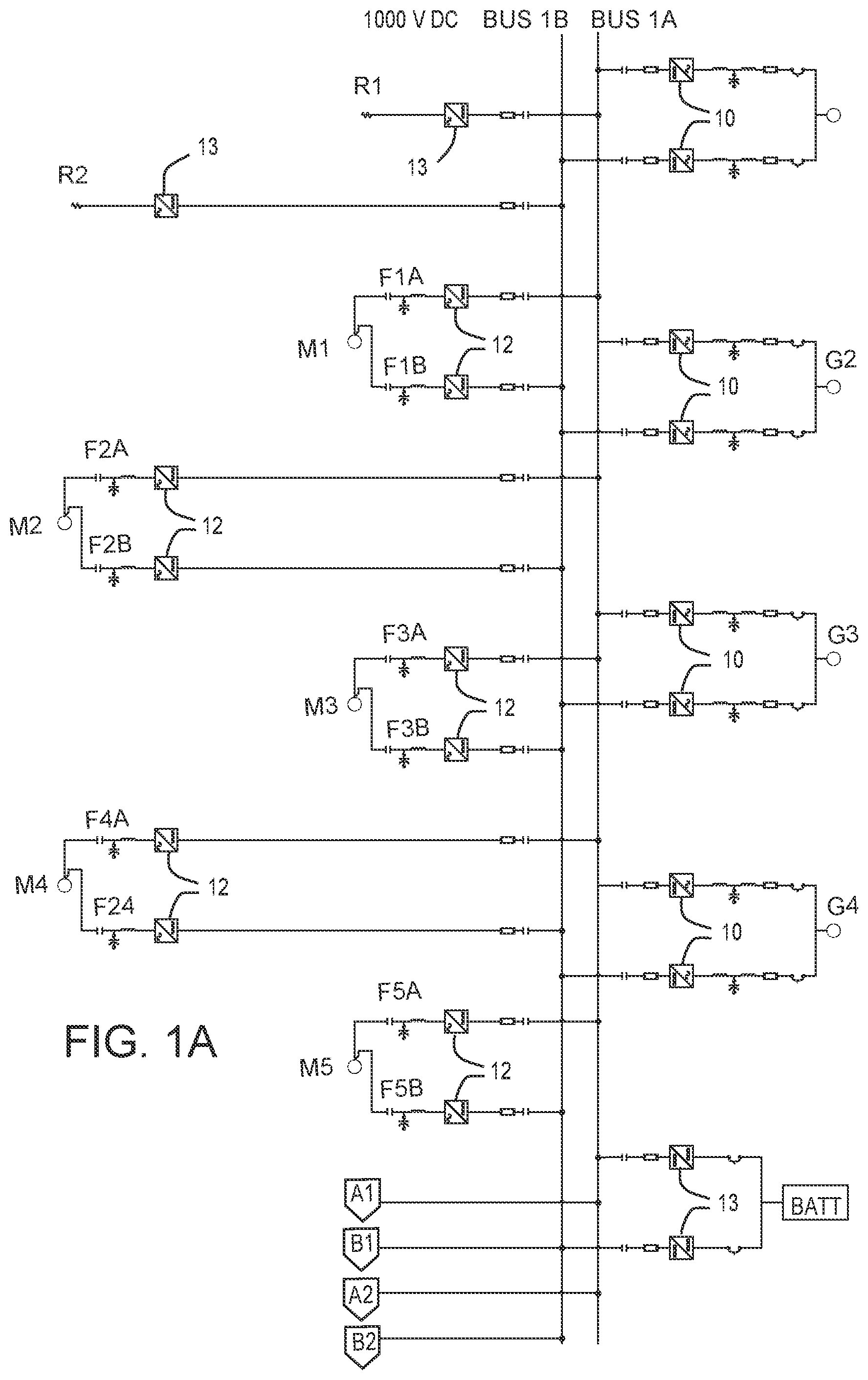
In the embodiment illustrated in , generators G 1 to G 4 may produce AC power at 480V, 690V or higher. Isolated power source inverters 10 , e.g., AFE inverters, convert the AC output of generators G 1 to G 4 to DC and galvanically isolate at least two 1000 VDC class main (primary) bus systems BUS 1 A, BUS 1 B. Each generator is connected to at least two of the isolated AFE inverters 10 . The AFE inverters 10 on BUS 1 A load share with all active inverters 10 on BUS 1 A via adjustable settings within the inverter (DC Bus Voltage Reference, Droop %). The AFE inverters 10 on BUS 1 B load share with all active inverters 10 on BUS 1 B via adjustable settings within the inverter (DC Bus Voltage Reference, Droop %). Each AFE 10 that feeds a bus can be sized to provide the desired amount of redundancy. For example, each AFE 10 can be sized up to 100%+ of the generator's capacity.
The AFE inverters 10 allow generators G 1 to G 4 to load share while being galvanically isolated from each other, without synchronization. The AFE inverters 10 eliminate harmonics, correct power factor to near 1.0, boost the AC voltage from generators G 1 to G 4 when converted to DC and precisely control the DC bus voltage of main bus systems BUS 1 A, BUS 1 B. The AFE inverters 10 are capable of balanced load sharing independently without communicating with each other via adjustable settings within the inverter (DC Bus Voltage Reference, Droop %), thus providing a naturally load balanced power conversion system.
As illustrated in A , energy storage system(s) BATT are each connected to main bus systems Bus 1 A, Bus 1 B via multiple DC/DC converters 11 . The energy storage system(s) BATT may be charged by any of generators G 1 to G 4 and supply power to main bus systems BUS 1 A, BUS 1 B when loads exceed running generator capacity or when none of generators G 1 to G 4 are in operation.
In the embodiment illustrated in A , main drive motors M 1 to M 5 are supplied with power from main bus systems BUS 1 A, BUS 1 B. For example, main drive motors M 1 and M 5 may be port and starboard drives drawing 1850 KW each, while main drive motors M 2 to M 4 may be bow thrusters drawing 1050 KW each. Each of the main drive motors M 1 to M 5 may be fed by a pair of isolated parallel DC/AC inverters 12 with a master controller (not shown) for each pair. One of the pair of inverters 12 for each motor is fed from BUS 1 A and the other inverter 12 is fed from BUS 1 B. Inverters 12 are connected to motors M 1 to M 5 via inductor/capacitor filters F 1 A to F 5 B. Load sharing between the inverters 12 is controlled by inverter software that communicates with the inverters 12 via a fiber optic cable (not shown). Inverters 12 actively synchronize their AC outputs which are tied together to redundantly feed a single load while maintaining galvanic isolation of the separate DC bus systems BUS 1 A, BUS 1 B. If one inverter 12 goes down, the other inverter 12 can remain active if the master controller is operational. Each inverter 12 can be sized for up to 100%+ of the motor load. One 50% inverter is capable of spinning a thruster driven by a motor to approximately 65-70% of maximum speed.
In addition, overvoltage conditions on main bus systems BUS 1 A, BUS 1 B may be controlled or mitigated by brake resistors R 1 , R 2 , connected to main bus systems BUS 1 A, BUS 1 B, respectively, via brake choppers 13 .
As indicated by the off-page connectors A 1 , B 1 , A 2 , B 2 on A and 1 B , in the embodiment illustrated in A and 1 B , the 1000 VDC Bus System BUS 1 A, BUS 1 B is connected to a secondary 710 VDC bus system BUS 2 A, BUS 2 B. Although only one secondary bus system is illustrated in B , there may be two or more 710 VDC bus systems. Each 710 VDC bus system BUS 2 A, BUS 2 B is dual fed from the 1000 VDC bus system BUS 1 A, BUS 1 B by a pair of DC/DC converters 14 that load share to make sure that 710 VDC Bus 2 A is equally sourced from 1000 VDC bus system BUS 1 A, BUS 1 B and that the 710 VDC BUS 2 B is equally sourced from the 1000 VDC bus system BUS 1 A, BUS 1 B. 710 VDC bus system BUS 2 A, BUS 2 B is isolated from 1000 VDC bus system BUS 1 A, BUS 1 B by DC/DC converters 14 . As a result 1000 VDC bus system BUS 1 A, BUS 1 B can be completely isolated while the vessel is on shore power for maintenance of 1000 VDC bus system BUS 1 A, BUS 1 B.
In the embodiment illustrated in B , hotel loads and smaller motors are supplied with power from 710 VDC bus system BUS 2 A, BUS 2 B. A pair of 480 VAC load centers 16 , each fed by a grid inverter 17 via a 480V input/480V output isolation transformer 18 , provide for nonessential non-motor loads. The 480V input/480V output isolation transformer prevents common mode voltages from occurring. Individual non-essential motors m 1 to m 5 are supplied with power from the 710 VDC bus system BUS 2 A, BUS 2 B by variable frequency drive controllers 20 .
A pair of 480 VAC grid inverters 22 , one from BUS 2 A and the other from BUS 2 B provide a parallel and redundant source of power for emergency panel 24 . This allows for hot sync to and from emergency generator EG when normal and emergency power are available.
A shore power inverter 26 is connected to 710 VDC BUS 2 A allowing for hot sync to and from shore power SR One of the grid inverters 22 connected to emergency panel EP can be used to safely back feed 710 VDC BUS 2 B when 710 VDC BUS 2 A is connected to shore power SP.
The embodiment described above provides all of the following benefits simultaneously:
•
• (1) galvanically isolated variable frequency operation of all generators; • (2) balanced load sharing between galvanically isolated redundant DC bus systems; • (3) enhanced redundancy without the use of tie breakers or a ring bus system; • (4) differentiated worst case single point failure analysis with no zero voltage conditions; • (5) ability to balance loads with odd numbers of generators or battery systems and load share with multiple different sized generators; • (6) a self-healing system in which failure is isolated to the part of the system that fails; and • (7) seamless closed transition to and from shore power.
For example, the naturally load balanced DC buses BUS 1 A, BUS 1 B have several advantages over the power distribution system illustrated in of U.S. Pat. No. 8,946,928. This known system has four generators, each generator connected via dual thyristor rectifiers to two DC distribution buses. Four AC motors are powered by the distribution system illustrated in of the '928 patent with two AC motors connected to each bus via DC/AC inverters. As a result, a single bus failure results in loss of power to half of the four motors. In other words, while there is redundant power generation, the distribution system illustrated in of the '928 patent is not load balanced or fault redundant. Thus, a single power bus failure in the system described above continues to supply power to all motors, possibly reduced depending on the capacity of the inverters, unlike the distribution system illustrated in of the '928 patent.
The many features and advantages of the embodiments are apparent from the detailed specification and, thus, it is intended by the appended claims to cover all such features and advantages of the embodiments that fall within the true spirit and scope thereof. Further, since numerous modifications and changes will readily occur to those skilled in the art, it is not desired to limit the inventive embodiments to the exact construction and operation illustrated and described, and accordingly all suitable modifications and equivalents may be resorted to, falling within the scope thereof.
Figures (2)
Citations
This patent cites (38)
- US249191
- US598424
- US873818
- US3127865
- US4164661
- US4661714
- US6188139
- US7544108
- US7980905
- US8062081
- US8159082
- US8706330
- US8946928
- US9148080
- US9154067
- US9413164
- US9550556
- US9745038
- US9780643
- US9899842
- US9941772
- US10020652
- US10541536
- US10734930
- US10770895
- US10938215
- US10974802
- US20040102109
- US20080143182
- US20100283318
- US20150295403
- US20150326022
- US20170101167
- US20170373502
- US20200212669
- US20210376602
- US0 730 333
- US2 445 382