Abstract
An electrical wire processing device ( 1 ) includes a pair of cutting blades ( 40 A, 40 B) capable of cutting an electrical wire ( 5 ) and circumferentially notching a covering ( 5 b ), a slit blade ( 43 A, 43 B) disposed farther in one side in a longitudinal direction (CL) of the electrical wire ( 5 ) than the cutting blades ( 40 A, 40 B) and capable of slitting the covering ( 5 b ) in the longitudinal direction (CL) of the electrical wire ( 5 ), and a slit blade actuator ( 35 A, 35 B) that moves the slit blade ( 43 A, 43 B) between a slit position in which the slit blade ( 43 A, 43 B) comes closer to the electrical wire ( 5 ) than the cutting blades ( 40 A, 40 B) and a retraction position in which the slit blade ( 43 A, 43 B) goes farther from the electrical wire ( 5 ) than the cutting blades ( 40 A, 40 B).
Claims (13)
1. An electrical wire processing device that processes an electrical wire having a core wire and a covering that covers a periphery of the core wire, the electrical wire processing device comprising: a pair of cutting blades capable of cutting the electrical wire and circumferentially notching the covering; a slit blade disposed farther in one side in a longitudinal direction of the electrical wire than the cutting blades and capable of slitting the covering in the longitudinal direction of the electrical wire; and a slit blade actuator that moves the slit blade between a slit position in which the slit blade comes closer to the electrical wire than the cutting blades and a retraction position in which the slit blade goes farther from the electrical wire than the cutting blades.
8. An electrical wire processing device that processes an electric wire having a core wire and a covering that covers a periphery of the core wire, the electrical wire processing device comprising: a pair of cutting blades capable of cutting the electrical wire and circumferentially notching the covering; a pair of first stripping blades disposed farther in one side in a longitudinal direction of the electrical wire than the cutting blades and capable of circumferentially notching the covering; a pair of second stripping blades disposed farther in the other side in the longitudinal direction of the electrical wire than the cutting blades and capable of circumferentially notching the covering; a slit blade disposed farther in the one side or the other side in the longitudinal direction of the electrical wire than the cutting blades and capable of slitting the covering in the longitudinal direction of the electrical wire; and a slit blade actuator that moves the slit blade between a slit position in which the slit blade comes closer to the electrical wire than the cutting blades, the first stripping blades, and the second stripping blades and a retraction position in which the slit blade goes farther from the electrical wire than the cutting blades, the first stripping blades, and the second stripping blades.
Show 11 dependent claims
2. The electrical wire processing device according to claim 1 , further comprising: a clamp member that is disposed farther in the one side in the longitudinal direction of the electrical wire than slit blade and holds the electrical wire; and a clamp actuator that relatively moves the clamp member and the slit blade along the longitudinal direction of the electrical wire.
3. The electrical wire processing device according to claim 2 , further comprising: a main actuator that drives the pair of cutting blades such that the cutting blades come closer to each other and separate from each other; and a controller that controls the slit blade actuator, the clamp actuator, and the main actuator, wherein the controller includes a first position notching control section that circumferentially notches a first position in a middle portion of the covering of the electrical wire by driving the main actuator such that the cutting blades move toward the electrical wire while holding the slit blade in the retraction position, a first slit blade control section that notches the covering by driving the slit blade actuator to move the slit blade to the slit position and moving the slit blade toward the electrical wire, a second slit blade control section that relatively moves the slit blade with respect to the covering between the first position and a second position by driving the clamp actuator, and a second position notching control section that moves the slit blade to the retraction position by driving the slit blade actuator and circumferentially notches the second position of the covering by driving the main actuator such that the cutting blades move toward the electrical wire.
4. The electrical wire processing device according to claim 3 , further comprising: a slit blade supporting member that supports the slit blade such that the slit blade is movable between the slit position and the retraction position and is joined to a corresponding one of the cutting blades to move with the cutting blade to come closer to and separate from the electrical wire, wherein the first slit blade control section is configured to move the slit blade toward the electrical wire to notch the covering by driving the main actuator.
5. The electrical wire processing device according to claim 1 , further comprising: a pair of stripping blades disposed farther in one side or the other side in the longitudinal direction of the electrical wire than the cutting blades and capable of circumferentially notching the covering.
6. The electrical wire processing device according to claim 3 , further comprising: a pair of stripping blades disposed farther in one side or the other side in the longitudinal direction of the electrical wire than the cutting blades and capable of circumferentially notching the covering, wherein each of the stripping blades is joined to a corresponding one of the cutting blades to move with the cutting blade to come closer to and separate from the electrical wire, the clamp actuator is configured to relatively move the clamp member and the stripping blades along the longitudinal direction of the electrical wire, the controller includes a cutting control section that cuts the electrical wire by driving the main actuator such that the cutting blades move toward the electrical wire while holding the slit blade in the retraction position, a stripping blade notching control section that circumferentially notches an end portion of the covering of the electrical wire by driving the main actuator such that the stripping blades move toward the end portion of the cut electrical wire while holding the slit blade in the retraction position, and a stripping control section that relatively moves the clamp member and the stripping blades in the longitudinal direction of the electrical wire by driving the clamp actuator in a state where the end portion of the covering of the electrical wire is being notched by the stripping blades while holding the slit blade in the retraction position.
7. The electrical wire processing device according to claim 5 , wherein the slit blade is disposed farther in the one side in the longitudinal direction of the electrical wire than the stripping blades.
9. The electrical wire processing device according to claim 8 , further comprising: a first clamp member that is disposed farther in the one side in the longitudinal direction of the electrical wire than the first stripping blades and the slit blade and holds the electrical wire; a second clamp member that is disposed farther in the other side in the longitudinal direction of the electrical wire than the second stripping blades and the slit blade and holds the electrical wire; a first clamp actuator that relatively moves the first clamp member and the slit blade along the longitudinal direction of the electrical wire; and a second clamp actuator that relatively moves the second clamp member and the slit blade along the longitudinal direction of the electrical wire.
10. The electrical wire processing device according to claim 9 , further comprising: a main actuator that drives the pair of cutting blades such that the cutting blades come closer to each other and separate from each other; and a controller that controls the slit blade actuator, the first clamp actuator, the second clamp actuator, and the main actuator, wherein the controller includes a first position notching control section that circumferentially notches a first position in a middle portion of the covering of the electrical wire by driving the main actuator such that the cutting blades move toward the electrical wire while holding the slit blade in the retraction position, a first slit blade control section that notches the covering by driving the slit blade actuator to move the slit blade to the slit position and moving the slit blade toward the electrical wire, a second slit blade control section that relatively moves the slit blade with respect to the covering between the first position and a second position by driving the first clamp actuator or the second clamp actuator, and a second position notching control section that moves the slit blade to the retraction position by driving the slit blade actuator and circumferentially notches the second position of the covering by driving the main actuator such that the cutting blades move toward the electrical wire.
11. The electrical wire processing device according to claim 10 , further comprising: a slit blade supporting member that supports the slit blade such that the slit blade is movable between the slit position and the retraction position and is joined to a corresponding one of the cutting blades to move with the cutting blade to come closer to and separate from the electrical wire, wherein the first slit blade control section is configured to move the slit blade toward the electrical wire to notch the covering by driving the main actuator.
12. The electrical wire processing device according to claim 10 , wherein each of the first stripping blades and each of the second stripping blades are joined to a corresponding one of the cutting blades to move with the cutting blade to come closer to and separate from the electrical wire, the first clamp actuator is configured to relatively move the first clamp member and the first stripping blades along the longitudinal direction of the electrical wire, the second clamp actuator is configured to relatively move the second clamp member and the second stripping blades along the longitudinal direction of the electrical wire, and the controller includes a cutting control section that cuts and divides the electrical wire into a first electrical wire in the one side in the longitudinal direction of the electrical wire and a second electrical wire in the other side in the longitudinal direction of the electrical wire by driving the main actuator such that the cutting blades move toward the electrical wire while holding the slit blade in the retraction position, a stripping blade notching control section that circumferentially notches end portions of the coverings of the first electrical wire and the second electrical wire by driving the main actuator such that the first stripping blades move toward the end portion of the divided first electrical wire and the second stripping blades move toward the end portion of the divided second electrical wire while holding the slit blade in the retraction position, and a stripping control section that relatively moves the first clamp member and the first stripping blades in the longitudinal direction of the first electrical wire and relatively moves the second clamp member the second stripping blades in the longitudinal direction of the second electrical wire by driving the first clamp actuator and the second clamp actuator in a state where the end portion of the covering of the first electrical wire is being notched by the first stripping blades and the end portion of the covering of the second electrical wire is being notched by the second stripping blades while holding the slit blade in the retraction position.
13. The electrical wire processing device according to claim 8 , wherein the slit blade is disposed farther in the one side in the longitudinal direction of the electrical wire than the first stripping blades or is disposed farther in the other side in the longitudinal direction of the electrical wire than the second stripping blades.
Full Description
Show full text →
BACKGROUND OF THE INVENTION
Technical Field
The present invention relates to an electrical wire processing device that can cut an electrical wire and strip a covering.
Background Art
Conventionally, electrical wire processing devices that perform a process of cutting an electrical wire and a process of stripping a covering of a middle portion of the electrical wire have been known (see, for example, Patent Document 1).
An electrical wire processing device disclosed in Patent Document 1 includes a pair of upper and lower cutting and notch cutters and a pair of upper and lower slit cutters disposed on right of the cutting and notch cutters. In the electrical wire processing device, in stripping a covering of a middle portion of an electrical wire, first, a first position in the covering of the middle portion of the electrical wire is circumferentially notched by the cutting and notch cutters. Next, the electrical wire is moved to right to be disposed between the pair of upper and lower slit cutters. Then, the covering of the middle portion of the electrical wire is slitted from the first position to a second position along a longitudinal direction of the electrical wire by the slit cutters. Thereafter, the electrical wire is moved to left to be disposed between the pair of upper and lower cutting and notch cutters again. Then, the second position in the covering of the middle portion of the electrical wire is circumferentially notched by the cutting and notch cutters. Thus, the covering of the middle portion is stripped.
CITATION LIST
Patent Document
•
• PATENT DOCUMENT: Japanese Laid-open Patent Publication No. H5-30621
SUMMARY OF THE INVENTION
Problem to be Solved by Invention
In the electrical wire processing device described above, using the cutting and notch cutters that perform a process of cutting the electrical wire, a part of a process of stripping the covering of the middle portion of the electrical wire (that is, a process of circumferentially notching the covering) can be performed. However, in performing the process of stripping the covering of the middle portion of the electrical wire, the electrical wire needs to be moved to left and right. Therefore, there is a problem in which an effort and a time are required for performing the process of stripping the covering of the middle portion of the electrical wire.
In view of the foregoing, the present invention has been devised and it is therefore an object of the present invention to, in an electrical wire processing device that can perform a process of cutting an electrical wire and a process of stripping a covering of a middle portion of the electrical wire, enable performing these processes quickly and efficiently.
Solution to Problem
An electrical wire processing device according to the present invention is an electrical wire processing device that processes an electrical wire having a core wire and a covering that covers a periphery of the core wire and includes a pair of cutting blades capable of cutting the electrical wire and circumferentially notching the covering, a slit blade disposed farther in one side in a longitudinal direction of the electrical wire than the cutting blades and capable of slitting the covering in the longitudinal direction of the electrical wire, and a slit blade actuator that moves the slit blade between a slit position in which the slit blade comes closer to the electrical wire than the cutting blades and a retraction position in which the slit blade goes farther from the electrical wire than the cutting blades.
According to the above-described electrical wire processing device, a process of cutting the electrical wire by moving the pair of cutting blades in a direction in which the cutting blades come closer to each other (which will be hereinafter referred to as a cutting process) while the slit blade is held in the retraction position can be performed.
After moving the slit blade to the slit position and moving the slit blade toward the electrical wire to notch the covering, the covering of a middle portion of the electrical wire can be slitted along the longitudinal direction of the electrical wire by relatively moving the slit blade and the electrical wire such that the slit blade relatively moves along the longitudinal direction of the electrical wire. Both sides of a slitted portion of the covering can be circumferentially notched by moving the pair of cutting blades closer to each other while the slit blade is held in the retraction position. Thus, a process of stripping the covering of the middle portion of the electrical wire (which will be hereinafter referred to as a middle portion stripping process) can be performed.
According to the electrical wire processing device, the cutting blades and the slit blade are disposed along the longitudinal direction of the electrical wire. Therefore, in the middle portion stripping process, an operation of moving the electrical wire in a direction perpendicular to the longitudinal direction is not needed. Accordingly, the middle portion stripping process can be performed quickly and efficiently. According to the electrical wire processing device, the cutting process, and the middle portion stripping process can be performed quickly and efficiently.
According to one preferred aspect of the present invention, the electrical wire processing device further includes a clamp member that is disposed farther in the one side in the longitudinal direction of the electrical wire than the slit blade and holds the electrical wire, and a clamp actuator that relatively moves the clamp member and the slit blade along the longitudinal direction of the electrical wire.
According to the above-described aspect, the clamping member can hold the electrical wire. The clamping member and the slit blade can be moved along the longitudinal direction of the electrical wire while the clamping member holds the electrical wire. Therefore, the cutting process and the middle portion stripping process can be favorably performed.
According to one preferred aspect of the present invention, the electrical wire processing device further includes a main actuator that drives the pair of cutting blades such that the cutting blades come closer to each other and separate from each other and a controller that controls the slit blade actuator, the clamp actuator, and the main actuator. The controller includes a first position notching control section that circumferentially notches a first position in a middle portion of the covering of the electrical wire by driving the main actuator such that the cutting blades move toward the electrical wire while holding the slit blade in the retraction position, a first slit blade control section that notches the covering by driving the slit blade actuator to move the slit blade to the slit position and moving the slit blade toward the electrical wire, a second slit blade control section that relatively moves the slit blade with respect to the covering between the first position and a second position by driving the clamp actuator, and a second position notching control section that moves the slit blade to the retraction position by driving the slit blade actuator and circumferentially notches the second position of the covering by driving the main actuator such that the cutting blades move toward the electrical wire.
According to the above-described aspect, the middle portion stripping process is automatically executed by the controller.
According to one preferred aspect of the present invention, the electrical wire processing device further includes a slit blade supporting member that supports the slit blade such that the slit blade is movable between the slit position and the retraction position and is joined to a corresponding one of the cutting blades to move with the cutting blade to come closer to and separate from the electrical wire. The first slit blade control section is configured to move the slit blade toward the electrical wire to notch the covering by driving the main actuator.
According to the above-described aspect, the slit blade can be moved toward the electrical wire to notch the covering by the main actuator that drives the cutting blades. Therefore, a dedicated actuator for moving the slit blade toward the electrical wire to notch the covering is not needed. Accordingly, the number of actuators can be reduced, and a cost and a size of the electrical wire processing device can be reduced.
According to one preferred aspect of the present invention, the electrical wire processing device further includes a pair of stripping blades disposed farther in one side or the other side in the longitudinal direction of the electrical wire than the cutting blades and capable of circumferentially notching the covering.
According to the above-described aspect, the covering of the end portion of the cut electrical wire can be circumferentially notched by moving the pair of stripping blades in a direction in which the stripping blades come closer to each other while the slit blade is held in the retraction position. Then, by relatively moving the stripping blades and the electrical wire such that the stripping blades relatively move to a tip end of the electrical wire, a process of stripping the covering of the end portion of the electrical wire (which will be hereinafter referred to as an end portion stripping process) can be performed. According to the above-described aspect, the cutting process, the end portion stripping process, and the middle portion stripping process can be performed quickly and efficiently.
According to one preferred aspect of the present invention, the electrical wire processing device further includes a pair of stripping blades disposed farther in one side or the other side in the longitudinal direction of the electrical wire than the cutting blades and capable of circumferentially notching the covering. Each of the stripping blades is joined to a corresponding one of the cutting blades to move with the cutting blade to come closer to and separate from the electrical wire. The clamp actuator is configured to relatively move the clamp member and the stripping blades along the longitudinal direction of the electrical wire. The controller includes a cutting control section that cuts the electrical wire by driving the main actuator such that the cutting blades move toward the electrical wire while holding the slit blade in the retraction position, a stripping blade notching control section that circumferentially notches an end portion of the covering of the electrical wire by driving the main actuator such that the stripping blades move toward the end portion of the cut electrical wire while holding the slit blade in the retraction position, and a stripping control section that relatively moves the clamp member and the stripping blades in the longitudinal direction of the electrical wire by driving the clamp actuator in a state where the end portion of the covering of the electrical wire is being notched by the stripping blades while holding the slit blade in the retraction position.
According to the above-described aspect, the cutting process and the end portion stripping process can be automatically executed by the controller.
According to one preferred aspect of the present invention, the slit blade is disposed farther in the one side in the longitudinal direction of the electrical wire than the stripping blades.
According to the above-described aspect, the slit blade is disposed in a side opposite to a side in which the cutting blades are provided with respect to the stripping blades. A margin in space is relatively large in the side of the stripping blades opposite to the side thereof in which the cutting blades are provided, and therefore, setting of the slit blades is facilitated.
Another electrical wire processing device according to the present invention is an electrical wire processing device that processes an electric wire having a core wire and a covering that covers a periphery of the core wire and includes a pair of cutting blades capable of cutting the electrical wire and circumferentially notching the covering, a pair of first stripping blades disposed farther in one side in a longitudinal direction of the electrical wire than the cutting blades and capable of circumferentially notching the covering, a pair of second stripping blades disposed farther in the other side in the longitudinal direction of the electrical wire than the cutting blades and capable of circumferentially notching the covering, a slit blade disposed farther in the one side or the other side in the longitudinal direction of the electrical wire than the cutting blades and capable of slitting the covering in the longitudinal direction of the electrical wire, and a slit blade actuator that moves the slit blade between a slit position in which the slit blade comes closer to the electrical wire than the cutting blades, the first stripping blades, and the second stripping blades and a retraction position in which the slit blade goes farther from the electrical wire than the cutting blades, the first stripping blades, and the second stripping blades.
According to the electrical wire processing device, the cutting process can be performed by moving the pair of cutting blades in the direction in which the cutting blades come closer to each other while the slit blade is held in the retraction position.
Also, by moving the pair of first stripping blades and the pair of the second stripping blades in a direction in which the pair of first stripping blades come closer to each other and the pair of the second stripping blades come closer to each other while the slit blade is held in the retraction position, the coverings of the end portions of the cut electrical wire in one side and the other side can be circumferentially notched. Then, by relatively moving the first and second stripping blades such that each of the first and second stripping blades relatively moves to a corresponding tip end of the covering, the end stripping process for both the end portions of the electrical wire can be performed.
Furthermore, by, after moving the slit blade to the slit position and moving the slit blade in a direction in which the slit blade comes closer to the electrical wire to notch the covering, relatively moving the stripping blades and the electrical wire such that the slit blade relatively moves along the longitudinal direction of the electrical wire, the covering of the middle portion of the electrical wire can be slitted along the longitudinal direction of the electrical wire. Also, by moving the pair of cutting blades in the direction in which the cutting blades come closer to each other while the slit blade is held in the retraction position, both sides of the slitted portion of the covering can be circumferentially notched. Thus, the middle portion stripping process can be performed.
According to the electrical wire processing device, the cutting blades, the first stripping blades, the second stripping blades, and the slit blade are disposed along the longitudinal direction of the electrical wire. Therefore, in the middle portion stripping process, an operation of moving the electrical wire in a direction perpendicular to the longitudinal direction is not needed. Accordingly, the middle portion stripping process can be performed quickly and efficiently. Also, when one of the cutting process, the end portion stripping process, and the middle portion stripping process is shifted to another one of the processes, the operation of moving the electrical wire in a direction perpendicular to the longitudinal direction is not needed. Therefore, according to the electrical wire processing device, the cutting process, the end portion stripping process, and the middle portion stripping process can be performed quickly and efficiently.
According to one preferred aspect of the present invention, the electrical wire processing device further includes a first clamp member that is disposed farther in the one side in the longitudinal direction of the electrical wire than the first stripping blades and the slit blade and holds the electrical wire, a second clamp member that is disposed farther in the other side in the longitudinal direction of the electrical wire than the second stripping blades and the slit blade and holds the electrical wire, a first clamp actuator that relatively moves the first clamp member and the slit blade along the longitudinal direction of the electrical wire, and a second clamp actuator that relatively moves the second clamp member and the slit blade along the longitudinal direction of the electrical wire.
According to the above-described aspect, the first and second clamp members can hold the electrical wire. Also, while the electrical wire is held, the first clamp member and the slit blade can be relatively moved along the longitudinal direction of the electrical wire and the second clamp member and the slit blade can be relatively moved along the longitudinal direction of the electrical wire. Therefore, the cutting process, the end portion stripping process, and the middle portion stripping process can be favorably performed.
According to one preferred aspect of the present invention, the electrical wire processing device further includes a main actuator that drives the pair of cutting blades such that the cutting blades come closer to each other and separate from each other, and a controller that controls the slit blade actuator, the first clamp actuator, the second clamp actuator, and the main actuator. The controller includes a first position notching control section that circumferentially notches a first position in a middle portion of the covering of the electrical wire by driving the main actuator such that the cutting blades move toward the electrical wire while holding the slit blade in the retraction position, a first slit blade control section that notches the covering by driving the slit blade actuator to move the slit blade to the slit position and moving the slit blade toward the electrical wire, a second slit blade control section that relatively moves the slit blade with respect to the covering between the first position and a second position by driving the first clamp actuator or the second clamp actuator, and a second position notching control section that moves the slit blade to the retraction position by driving the slit blade actuator and circumferentially notches the second position of the covering by driving the main actuator such that the cutting blades move toward the electrical wire.
According to the above-described aspect, the middle portion stripping process can be automatically executed by the controller.
According to one preferred aspect of the present invention, the electrical wire processing device further includes a slit blade supporting member that supports the slit blade such that the slit blade is movable between the slit position and the retraction position and is joined to a corresponding one of the cutting blades to move with the cutting blade to come closer to and separate from the electrical wire. The first slit blade control section is configured to move the slit blade toward the electrical wire to notch the covering by driving the main actuator.
According to the above-described aspect, the slit blade can be moved toward the electrical wire by the main actuator that drives the cutting blades to notch the covering. Therefore, a dedicated actuator for moving the slit blade toward the electrical wire to notch the covering is not needed. Accordingly, the number of actuators can be reduced and a cost and a size of the electrical wire processing device can be reduced.
According to one preferred aspect of the present invention, each of the first stripping blades and each of the second stripping blades are joined to a corresponding one of the cutting blades to move with the cutting blade to come closer to and separate from the electrical wire. The first clamp actuator is configured to relatively move the first clamp member and the first stripping blades along the longitudinal direction of the electrical wire. The second clamp actuator is configured to relatively move the second clamp member and the second stripping blades along the longitudinal direction of the electrical wire. The controller includes a cutting control section that cuts and divides the electrical wire into a first electrical wire in the one side in the longitudinal direction of the electrical wire and a second electrical wire in the other side in the longitudinal direction of the electrical wire by driving the main actuator such that the cutting blades move toward the electrical wire while holding the slit blade in the retraction position, a stripping blade notching control section that circumferentially notches end portions of the coverings of the first electrical wire and the second electrical wire by driving the main actuator such that the first stripping blades move toward the end portion of the divided first electrical wire and the second stripping blades move toward the end portion of the divided second electrical wire while holding the slit blade in the retraction position, and a stripping control section that relatively moves the first clamp member and the first stripping blades in the longitudinal direction of the first electrical wire and relatively moves the second clamp member and the second stripping blades in the longitudinal direction of the second electrical wire by driving the first clamp actuator and the second clamp actuator in a state where the end portion of the covering of the first electrical wire is being notched by the first stripping blades and the end portion of the covering of the second electrical wire is being notched by the second stripping blades while holding the slit blade in the retraction position.
According to the above-described aspect, the cutting process and the end portion stripping process for the end portions of both the electrical wires are automatically executed by the controller.
According to one preferred aspect of the present invention, the slit blade is disposed farther in the one side in the longitudinal direction of the electrical wire than the first stripping blades or is disposed farther in the other side in the longitudinal direction of the electrical wire than the second stripping blades.
According to the above-described aspect, the slit blade is disposed in a side opposite to a side in which the cutting blades are provided with respect to the first stripping blades or in a side opposite to a side in which the cutting blades are provided with respect to the second stripping blades. A margin in space is relatively large in the side of the first stripping blades opposite to the side thereof in which the cutting blades are provided and in the side of the second stripping blades opposite to the side thereof in which the cutting blades are provided, and therefore, setting of the slit blades is facilitated.
Effects of the Invention
According to the present invention, in an electrical wire processing device that can perform a process of cutting an electrical wire and a process of stripping a covering of a middle portion of the electrical wire, these processes can be performed quickly and efficiently.
BRIEF DESCRIPTION OF THE DRAWINGS
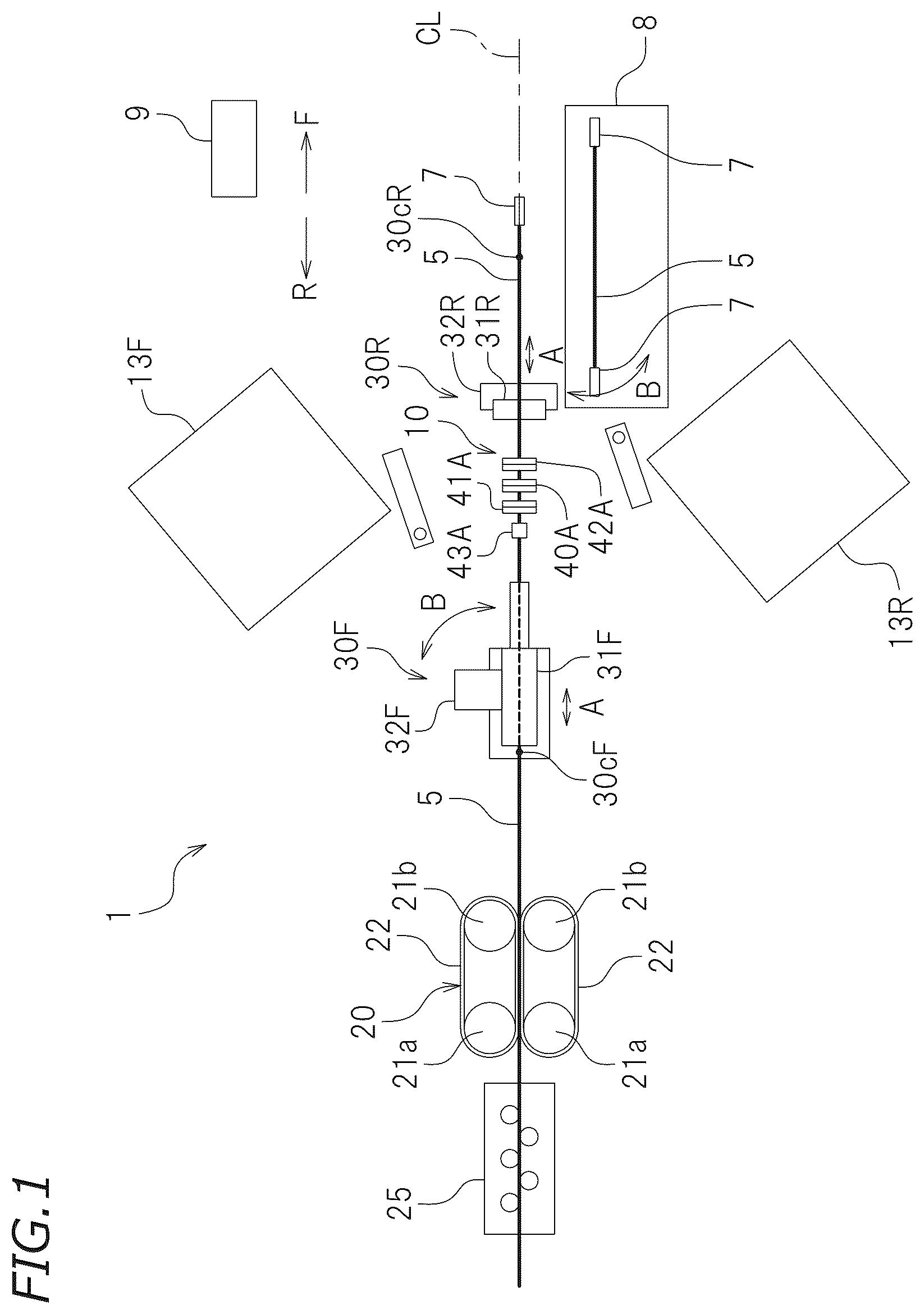
is a plan view schematically illustrating a configuration of an electrical wire processing device according to an embodiment.
is a perspective view of an electrical wire.
is a right side view of a cutter device.
is a block diagram of a control system of the electrical wire processing device.
is a right side view of a main portion of the cutter device when the electrical wire is cut.
is a right side view of the main portion of the cutter device when the electrical wire is notched by strip blades.
is a right side view of the main portion of the cutter device when a covering of an end portion of the electrical wire is stripped.
is a right side view of the main portion of the cutter device when a first position in the covering is notched by cutting blades.
is a right side view of the main portion of the cutter device when the electrical wire is moved rearward such that the first position of the covering is located between a pair of slit blades.
is a right side view of the main portion of the cutter device when the first position in the covering is notched by the slit blades.
is a right side view of the main portion of the cutter device when the covering is slitted from the first position to a second position by the slit blades.
is a right side view of the main portion of the cutter device when the slit blades are moved to a retraction position.
is a right side view of the main portion of the cutter device when the electrical wire is moved forward such that the second position in the covering is located between the pair of cutting blades.
is a right side view of the main portion of the cutter device when the second position of the covering is notched by the cutting blades.
DETAILED DESCRIPTION OF THE PREFERRED EMBODIMENTS
With reference to the attached drawings, preferred embodiments of the present invention will be described below. is a plan view schematically illustrating a configuration of an electrical wire processing device 1 according to an embodiment of the present invention. In the following description, assume that a right side and a left side in are a front side and a rear side, respectively. Assume that an upper side and a lower side in are a left side and a right side, respectively. Reference symbols F and R in the drawings indicate front and rear, respectively. However, these directions are used in the following description merely for convenience of description and do not limit the present invention.
The electrical wire processing device 1 includes a wire drawing machine 25 , a feeder 20 for feeding an electrical wire 5 , electrical wire clamp devices 30 F and 30 R, a cutter device 10 , crimping machines 13 F and 13 R, a controller 9 , and a tray 8 . As illustrated in , the electrical wire 5 is a so-called covered electrical wire, and includes a core wire 5 a formed of a conductor and a covering 5 b covering a periphery of the core wire 5 a and formed of an insulator.
The wire drawing machine 25 removes a curl of the electrical wire 5 and corrects the electrical wire 5 such that the electrical wire 5 becomes straight. The wire drawing machine 25 includes a plurality of rollers disposed in a staggered manner.
The feeder 20 includes a pair of left and right driving rollers 21 a , a pair of left and right driven rollers 21 b , and a pair of left and right conveyance belts 22 each of which is wound around a corresponding one of the driving rollers 21 a and a corresponding one of the driven rollers 21 b . By causing the conveyance belts 22 to run by the driving rollers 21 a , the electrical wire 5 sandwiched between the left and right conveyance belts 22 is sent forward. However, the feeder 20 may be a device that can send the electrical wire 5 and there is no limitation on a specific configuration thereof.
Each of the electrical wire clamp devices 30 F and 30 R can hold the electrical wire 5 , move along a longitudinal direction CL of the electrical wire 5 (see an arrow A), and turn around a corresponding one of vertical lines 30 c F and 30 c R (see an arrow B). The electrical wire clamp device 30 F includes a first clamp member 31 F that holds the electrical wire 5 , a first clamp actuator 32 F that moves the first clamp member 31 F in the longitudinal direction CL of the electrical wire 5 (a front-rear direction in this embodiment), and a first turning actuator 36 F (see ) that turns the first clamp member 31 F around the vertical line 30 c F. The electrical wire clamp device 30 R includes a second clamp member 31 R that holds the electrical wire 5 , a second clamp actuator 32 R that moves the second clamp member 31 R in the longitudinal direction CL of the electrical wire 5 , and a second turning actuator 36 R (see ) that turns the second clamp member 31 R around the vertical line 30 c R.
The cutter device 10 can cut the electrical wire 5 , strip the covering 5 b of an end portion of the electrical wire 5 , and strip the covering 5 b of a middle portion of the electrical wire 5 . A specific configuration of the cutter device 10 will be described later.
The crimping machines 13 F and 13 R crimp a terminal 7 to end portions of the electrical wire 5 . As described above, each of the electrical wire clamp devices 30 F and 30 R is configured to turn around a corresponding one of the vertical lines 30 c F and 30 c R. The crimping machine 13 F is configured to crimp the terminal 7 to a front end portion of the electrical wire 5 held by the electrical wire clamp device 30 F. The crimping machine 13 R is configured to crimp the terminal 7 to a rear end portion of the electrical wire 5 held by the electrical wire clamp device 30 R.
The tray 8 is a box body in which the electrical wire 5 after processing is collected. The tray 8 houses the electrical wire 5 to which the terminal 7 is crimped in both sides, the electrical wire 5 from which the covering 5 b of the middle portion has been stripped, or the like.
Next, a detailed configuration of the cutter device 10 will be described. is a right side view of the cutter device 10 . The cutter device 10 incudes a pair of upper and lower cutting blades 40 A and 40 B, a pair of upper and lower first stripping blades 41 A and 41 B disposed rearward of the cutting blades 40 A and 40 B, a pair of upper and lower second stripping blades 42 A and 42 B disposed forward of the cutting blades 40 A and 40 B, and a pair of upper and lower slit blades 43 A and 43 B disposed rearward of the first stripping blades 41 A and 41 B. The cutting blades 40 A and 40 B, the first stripping blades 41 A and 41 B, the second stripping blades 42 A and 42 B, and the slit blades 43 A and 43 B are disposed along the longitudinal direction CL of the electrical wire 5 . Specifically, the upper cutting blade 40 A, the upper first stripping blade 41 A, the upper second stripping blade 42 A, and the upper slit blade 43 A are disposed in line in the front-rear direction, and the lower cutting blade 40 B, the lower first stripping blade 41 B, the lower second stripping blade 42 B, and the lower slit blade 43 B are disposed in line in the front-rear direction. The cutter device 10 includes a frame 31 , a guide 15 provided in the frame 31 and extending up and down, an upper block 33 A and a lower block 33 B engaged with the guide 15 so as to be slidable up and down, and a main actuator 32 driving the upper block 33 A and the lower block 33 B up and down such that the upper block 33 A and the lower block 33 B come closer to each other or separate from each other.
The upper cutting blade 40 A, the upper first stripping blade 41 A, and the upper second stripping blade 42 A are supported by the upper block 33 A. Note that, in this specification, the expression “being supported” indicates both a case of being directly supported and a case of being indirectly supported via some other member, unless otherwise noted. In this embodiment, the upper cutting blade 40 A, the upper first stripping blade 41 A, and the upper second stripping blade 42 A are indirectly supported by the upper block 33 A and are configured to move up and down with the upper block 33 A. The upper stripping blades 41 A and 42 A are indirectly joined to the upper cutting blade 40 A to move up and down with the upper cutting blade 40 A. The lower cutting blade 40 B, the lower first stripping blade 41 B, and the lower second stripping blade 42 B are supported by the lower block 33 B and are configured to move up and down with the lower block 33 B. The lower first stripping blades 41 B and the lower second stripping blade 42 B are indirectly joined to the lower cutting blade 40 B to move up and down with the lower cutting blade 40 B.
The main actuator 32 may be an actuator that can drive the upper block 33 A and the lower block 33 B up and down, and there is no limitation on a type of the main actuator 32 . In this embodiment, the main actuator 32 is constituted by a servo motor. The main actuator 32 is configured to cause the upper block 33 A and the lower block 33 B to come closer to each other and separate from each other. When the upper block 33 A and the lower block 33 B move to come closer to each other, the upper cutting blade 40 A and the lower cutting blade 40 B come closer to each other, the upper first stripping blade 41 A and the lower first stripping blade 41 B come closer to each other, and the upper second stripping blade 42 A and the lower second stripping blade 42 B come closer to each other. That is, when the upper block 33 A and the lower block 33 B move to come closer to each other, the cutting blades 40 A and 40 B, the first stripping blades 41 A and 41 B, and the second stripping blades 42 A and 42 B move toward the electrical wire 5 . On the other hand, when the upper block 33 A and the lower block 33 B move to separate from each other, the upper cutting blade 40 A and the lower cutting blade 40 B separate from each other, the upper first stripping blade 41 A and the lower first stripping blade 41 B separate from each other, and the upper second stripping blade 42 A and the lower second stripping blade 42 B separate from each other. That is, when the upper block 33 A and the lower block 33 B move to separate from each other, the cutting blades 40 A and 40 B, the first stripping blades 41 A and 41 B, and the second stripping blades 42 A and 42 B move to separate from the electrical wire 5 .
An upper slit blade supporting member 34 A is fixed to the upper block 33 A. The upper slit blade supporting member 34 A is configured to move up and down with the upper block 33 A. The upper slit blade 43 A is supported so as to be movable up and down by the upper slit blade supporting member 34 A. The upper slit blade 43 A is movable up and down between a slit position in which the upper slit blade 43 A is closer to the electrical wire 5 than the upper cutting blade 40 A and the upper stripping blades 41 A and 42 A and a retraction position in which the upper slit blade 43 A goes farther from the electrical wire 5 than the upper cutting blade 40 A and the upper stripping blades 41 A and 42 A. A slit blade actuator 35 A that drives the upper slit blade 43 A up and down is fixed to the upper slit blade supporting member 34 A.
A lower slit blade supporting member 34 B is fixed to the lower block 33 B. The lower slit blade supporting member 34 B is configured to move up and down with the lower block 33 B. The lower slit blade 43 B is fixed to the lower slit blade supporting member 34 B so as to be movable up and down. The lower slit blade 43 B is movable up and down between a slit position in which the lower slit blade 43 B comes closer to the electrical wire 5 than the lower cutting blade 40 B and the lower stripping blades 41 B and 42 B and the retraction position in which the lower slit blade 43 B goes farther from the electrical wire 5 than the lower cutting blade 40 B and the lower stripping blades 41 B and 42 B. A slit blade actuator 35 B that drives the lower slit blade 43 B up and down is fixed to the lower slit blade supporting member 34 B.
Each of the slit blade actuators 35 A and 35 B can move a corresponding one of the upper and lower slit blades 43 A and 43 B to the slit position and the retraction position. In this embodiment, each of the slit blade actuators 35 A and 35 B is constituted by an air cylinder. However, each of the slit blade actuators 35 A and 35 B may be an actuator capable of moving a corresponding one of the slit blades 43 A and 43 B to the slit position and the retraction position and is not limited to the air cylinder. Each of the slit blade actuator 35 A and 35 B may be constituted by, for example, a solenoid or a motor.
As illustrated in , the controller 9 is communicably coupled to the wire drawing machine 25 , the feeder 20 , the electrical wire clamp devices 30 F and 30 R, the cutter device 10 , and the crimping machines 13 F and 13 R and controls operations thereof. The controller 9 may be a dedicated computer for the electrical wire processing device 1 and may be a general purpose computer, such as a personal computer or the like. The controller 9 includes a cutting control section 91 , a stripping blade notching control section 92 , a stripping control section 93 , a first position notching control section 94 , a second position notching control section 95 , a first slit blade control section 96 , and a second slit blade control section 97 . Note that a process performed by each of the sections 91 to 97 will be described later. In this embodiment, each of the above-described sections 91 to 97 is realized by executing a predetermined program by the computer.
Next, each process performed by the electrical wire processing device 1 will be described. As will be described below, the electrical wire processing device 1 can perform a process of cutting the electrical wire 5 (cutting process), a process of stripping the covering 5 b of an end portion of the cut electrical wire 5 (end portion stripping process), a process of crimping the terminal 7 to the end portion of the electrical wire 5 (terminal crimping process), and a process of stripping the covering 5 b of a middle portion of the electrical wire 5 (middle portion stripping process). Each process described below is executed by the controller 9 .
First, the cutting process will be described. In the cutting process, the cutting control section 91 of the controller 9 holds the slit blades 43 A and 43 B in the retraction position. The cutting control section 91 drives the main actuator 32 such that the electrical wire 5 is held by the first clamp member 31 F and the second clamp member 31 R and the cutting blades 40 A and 40 B move toward the electrical wire 5 . Specifically, the cutting control section 91 causes the cutting blades 40 A and 40 B to come closer to each other until respective edges of the cutting blades 40 A and 40 B cross each other. Thus, as illustrated in , the electrical wire 5 is cut and divided into a rear electrical wire 5 and a front electrical wire 5 by the cutting blades 40 A and 40 B. The cutting process is as described above.
Subsequently, as illustrated in , the stripping blade notching control section 92 of the controller 9 drives the main actuator 32 such that the first stripping blades 41 A and 41 B and the second stripping blades 42 A and 42 B move toward the electrical wire 5 . Thus, the covering 5 b of a front end portion of the rear electrical wire 5 is circumferentially notched by the first stripping blades 41 A and 41 B. The covering 5 b of a rear end portion of the front electrical wire 5 is circumferentially notched by the second stripping blades 42 A and 42 B. Next, as illustrated in , the stripping control section 93 of the controller 9 moves the first clamp member 31 F holding the rear electrical wire 5 rearward and moves the second clamp member 31 R holding the front electrical wire 5 forward. Then, the rear electrical wire 5 is pulled rearward and the covering 5 b of the front end portion of the rear electrical wire 5 is stripped by the first stripping blades 41 A and 41 B. The front electrical wire 5 is pulled forward and the covering 5 b of the rear end portion of the front electrical wire 5 is stripped by the second stripping blades 42 A and 42 B. Thus, the covering 5 b of the end portions of both the electrical wires 5 after being cut is stripped. The end portion stripping process is as described above.
When the end portion stripping process ends, the controller 9 turns the electrical wire clamp devices 30 F and 30 R (see ). The electrical wire clamp device 30 F turns leftward while holding the rear electrical wire 5 and guides the front end portion of the rear electrical wire 5 to the crimping machine 13 F. On the other hand, the electrical wire clamp device 30 R turns rightward while holding the front electrical wire 5 and guides the read end portion of the front electrical wire 5 to the crimping machine 13 R. Then, the terminal 7 is crimped to the front end portion of the rear electrical wire 5 and the rear end portion of the front electrical wire 5 by the crimping machines 13 F and 13 R. The terminal crimping process is as described above.
Thereafter, the electrical wire clamp device 30 F returns to an initial position (the position illustrated in ) opposed to the cutter device 10 while holding the rear electrical wire 5 , and releases holding of the electrical wire 5 . After releasing holding of the front electrical wire 5 , the electrical wire clamp device 30 R returns to an initial position (the position illustrated in ) opposed to the cutter device 10 . Note that, when the holding by the electrical wire clamp device 30 R is released, the front electrical wire 5 falls and is collected in the tray 8 .
Next, the middle portion stripping process will be described. First, the controller 9 causes the first clamp member 31 F and the second clamp member 31 R to hold the electrical wire 5 . Next, the first position notching control section 94 of the controller 9 drives the main actuator 32 such that the slit blades 43 A and 43 B are held in the retraction position and the cutting blades 40 A and 40 B move toward the electrical wire 5 . Specifically, the first position notching control section 94 causes the cutting blades 40 A and 40 B to come closer to each other such that each of the cutting blades 40 A and 40 B comes to a position just before a position in which the respective edges of the cutting blades 40 A and 40 B cross each other. Then, as illustrated in , the covering 5 b of the middle portion of the electrical wire 5 is circumferentially notched. Note that this notching position will be hereinafter referred to as a first position P 1 .
Next, as illustrated in , the controller 9 causes the cutting blades 40 A and 40 B to separate from each other and moves the electrical wire 5 rearward until the first position P 1 of the covering 5 b matches a position between the slit blades 43 A and 43 B. That is, the controller 9 moves the electrical wire 5 rearward until the first position P 1 of the covering 5 b matches a position directly below the upper slit blade 43 A and a position directly above the lower slit blade 43 B.
The first slit blade control section 96 of the controller 9 drives the slit blade actuators 35 A and 35 B to move the slit blades 43 A and 43 B from the retraction position to the slit position. Note that a timing of moving the slit blades 43 A and 43 B to the slit position may be before, after, and during moving the electrical wire 5 rearward. Next, the first slit blade control section 96 of the controller 9 drives the main actuator 32 such that the upper block 33 A and the lower block 33 B come closer to each other. Thus, the slit blades 43 A and 43 B move to come closer to each other. The first slit blade control section 96 moves the slit blades 43 A and 43 B toward the electrical wire 5 until the slit blades 43 A and 43 B notch the first position P 1 of the covering 5 b (see ).
Next, the second slit blade control section 97 of the controller 9 moves the electrical wire 5 forward while a state where the slit blades 43 A and 43 B are notching the covering 5 b by driving the first clamp actuator 32 F and the second clamp actuator 32 R is kept. Then, as illustrated in , the covering 5 b is slitted along the longitudinal direction CL of the electrical wire 5 by the slit blades 43 A and 43 B. The second slit blade control section 97 moves the electrical wire 5 forward until the slit blades 43 A and 43 B reach a preset second position P 2 of the covering 5 b . Thus, the electrical wire 5 is slitted from the first position P 1 of the covering 5 b to the second position P 2 thereof in the longitudinal direction CL.
Next, as illustrated in , the controller 9 drives the main actuator 32 such that the upper block 33 A and the lower block 33 B separate from each other.
The second position notching control section 95 of the controller 9 drives the slit blade actuators 35 A and 35 B to move the slit blades 43 A and 43 B from the slit position to the retraction position. Note that a timing of moving the slit blades 43 A and 43 B to the retraction position may be before, after, and during causing the upper block 33 A and the lower block 33 B to separate from each other. As illustrated in , the second position notching control section 95 of the controller 9 moves the electrical wire 5 forward until the second position P 2 of the covering 5 b matches a position between the cutting blades 40 A and 40 B. That is, the second position notching control section 95 moves the electrical wire 5 forward until the second position P 2 of the covering 5 b matches a position directly below the upper cutting blade 40 A and a position directly above the lower cutting blade 40 B. Note that a timing of moving the electrical wire 5 forward may be before, after, and during moving the slit blades 43 A and 43 B to the retraction position.
The second position notching control section 95 of the controller 9 drives the main actuator 32 such that, while the slit blades 43 A and 43 B are held in the retraction position, the cutting blades 40 A and 40 B move toward the electrical wire 5 . Specifically, the second position notching control section 95 causes the cutting blades 40 A and 40 B to come closer to each other such that each of the cutting blades 40 A and 40 B comes to a position just before a position in which the respective edges of the cutting blades 40 A and 40 B cross each other. Thus, as illustrated in , the covering 5 b is circumferentially notched in the second position P 2 by the cutting blades 40 A and 40 B. As a result, the covering 5 b of the middle portion of the electrical wire 5 is circumferentially notched in the first position P 1 and the second position P 2 and the electrical wire 5 is slitted from the first position P 1 to the second position P 2 in the longitudinal direction CL of the electrical wire 5 , and therefore, a portion of the covering 5 b between the first position P 1 and the second position P 2 is stripped. That is, the covering 5 b of the middle portion of the electrical wire 5 is stripped. The middle portion stripping process is as described above.
Note that there is no particular limitation on a timing of performing the above-described middle portion stripping process. The middle portion stripping process may be performed regardless of the end portion stripping process and the terminal crimping process. The middle portion stripping process may be performed after the cutting process and may be performed after the end portion stripping process. The middle portion stripping process may be performed after performing the cutting process, the end portion stripping process, and the terminal crimping process. Note that, in this case, the middle portion stripping process is performed on the rear electrical wire 5 .
As described above, the electrical wire processing device 1 according to this embodiment includes the slit blade actuators 35 A and 35 B that move the slit blades 43 A and 43 B to the slit position and the retraction position. The cutting blades 40 A and 40 B and the slit blades 43 A and 43 B are disposed along the longitudinal direction CL of the electrical wire 5 but, by moving the slit blades 43 A and 43 B to the retraction position, the covering 5 b of the middle portion of the electrical wire 5 can be circumferentially notched by the cutting blades 40 A and 40 B without being interfered by the slit blades 43 A and 43 B. On the other hand, by moving the slit blades 43 A and 43 B to the slit position, the covering 5 b of the middle portion of the electrical wire 5 can be slitted in the longitudinal direction by the slit blades 43 A and 43 B without being interfered by the cutting blades 40 A and 40 B. Therefore, By the electrical wire processing device 1 according to this embodiment, while the cutting blades 40 A and 40 B and the slit blades 43 A and 43 B are disposed along the longitudinal direction CL of the electrical wire 5 , the process of stripping the covering 5 b of the middle portion of the electrical wire 5 (middle portion stripping process) can be performed. Accordingly, in the middle portion stripping process, it is sufficient to move the electrical wire 5 in the longitudinal direction CL (that is, the front-rear direction) and an operation of moving the electrical wire 5 in a direction (for example, a left-right direction) perpendicular to the longitudinal direction CL is not needed. An operation of moving the electrical wire 5 in the longitudinal direction CL can be performed quickly and efficiently, as compared to the operation of moving the electrical wire 5 in the direction perpendicular to the longitudinal direction CL. Therefore, By the electrical wire processing device 1 according to this embodiment, the middle portion stripping process can be performed quickly and efficiently.
By the electrical wire processing device 1 according to this embodiment, the cutting process and the end portion stripping process can be performed by the cutting blades 40 A and 40 B, the first stripping blades 41 A and 41 B, and the second stripping blades 42 A and 42 B disposed along the longitudinal direction CL of the electrical wire 5 . In shifting from the cutting process to the end portion stripping process, the operation of moving the electrical wire 5 in the direction perpendicular to the longitudinal direction CL is not needed. In shifting from the cutting process or the end portion stripping process to the middle portion stripping process, and in sifting from the middle portion stripping process to the cutting process or the end portion stripping process, the operation of moving the electrical wire 5 in the direction perpendicular to the longitudinal direction CL is not needed. Therefore, by the electrical wire processing device 1 according to this embodiment, the cutting process, the end portion stripping process, and the middle portion stripping process can be performed quickly and efficiently.
The electrical wire processing device 1 according to this embodiment includes the first clamp member 31 F disposed rearward of the first stripping blades 41 A and 41 B and the slit blades 43 A and 43 B, the second clamp member 31 R disposed forward of the second stripping blades 42 A and 42 B and the slit blades 43 A and 43 B, the first clamp actuator 32 F that moves the first clamp member 31 F in the longitudinal direction CL of the electrical wire 5 , and the second clamp actuator 32 R that moves the second clamp member 31 R in the longitudinal direction CL of the electrical wire 5 . Therefore, the cutting process, the end portion stripping process for the end portions of both the electrical wires, and the middle portion stripping process can be favorably performed.
Note that different actuators may be provided for driving the cutting blades 40 A and 40 B, the first stripping blades 41 A and 41 B, and the second stripping blades 42 A and 42 B and for driving the slit blades 43 A and 43 B toward the electrical wire 5 . However, according to this embodiment, a single main actuator 32 serves as those actuators. By the main actuator 32 that drives the cutting blades 40 A and 40 B, the slit blades 43 A and 43 B can be moved toward the electrical wire 5 to notch the covering 5 b . According to this embodiment, the number of actuators can be reduced, so that a cost and a size of the electrical wire processing device 1 can be reduced.
In this embodiment, the slit blades 43 A and 43 B are disposed rearward of the first stripping blades 41 A and 41 B. That is, the slit blades 43 A and 43 B are disposed in a side opposite to a side in which the cutting blades 40 A and 40 B are provided with respect to the first stripping blades 41 A and 41 B. A margin in space is relatively large in the side of the first stripping blades 41 A and 41 B opposite to the side thereof in which the cutting blades 40 A and 40 B are provided. Therefore, according to this embodiment, the slit blades 43 A and 43 B can be easily set.
Note that there is no particular limitation on positions of the slit blades 43 A and 43 B. The slit blades 43 A and 43 B may be disposed forward of the second stripping blades 42 A and 42 B. That is, the slit blades 43 A and 43 B may be disposed in a side opposite to a side in which the cutting blades 40 A and 40 B are provided with respect to the second stripping blades 42 A and 42 B. Also in this case, setting of the slit blades 43 A and 43 B is facilitated.
On the other hand, in a case where there is a sufficient space between the cutting blades 40 A and 40 B and the first stripping blades 41 A and 41 B, the slit blades 43 A and 43 B may be disposed between the cutting blades 40 A and 40 B and the first stripping blades 41 A and 41 B. In a case where there is a sufficient space between the cutting blades 40 A and 40 B and the second stripping blades 42 A and 42 B, the slit blades 43 A and 43 B may be disposed between the cutting blades 40 A and 40 B and the second stripping blades 42 A and 42 B. Thus, a dimension of the cutter device 10 in the front-rear direction can be reduced, so that a size of the cutter device 10 can be reduced.
One embodiment of the present invention has been described above, but the above-described embodiment is merely an example. The present invention can be implemented in various other modes. Next, examples of other embodiments will be briefly described.
In the above-described embodiment, the cutting blades 40 A and 40 B, the first stripping blades 41 A and 41 B, the second stripping blades 42 A and 42 B, and the slit blades 43 A and 43 B are provided in pairs of upper and lower blades. However, the blades of each of the pairs of the cutting blades 40 A and 40 B, the first stripping blades 41 A and 41 B, the second stripping blades 42 A and 42 B, and the slit blades 43 A and 43 B may be disposed to face each other with the electrical wire 5 interposed therebetween and a disposition direction of each of the pairs is not limited to an up-down direction. For example, the cutting blades 40 A and 40 B, the first stripping blades 41 A and 41 B, the second stripping blades 42 A and 42 B, and the slit blades 43 A and 43 B may be provided in pairs of left and right blades.
In the above-described embodiment, the electrical wire processing device 1 includes the first stripping blades 41 A and 41 B disposed rearward of the cutting blades 40 A and 40 B and the second stripping blades 42 A and 42 B disposed forward of the cutting blades 40 A and 40 B such that the covering 5 b of both end portions of the electrical wire 5 after being cut can be simultaneously stripped. However, the first stripping blades 41 A and 41 B disposed rearward of the cutting blades 40 A and 40 B or the second stripping blades 42 A and 42 B disposed forward of the cutting blades 40 A and 40 B may not be provided. That is, a pair of stripping blades may be provided only rearward or forward of the cutting blades 40 A and 40 B.
In the above-described embodiment, the cutter device 10 includes a pair of slit blades 43 A and 43 B. However, as long as the covering 5 b of the middle portion of the electrical wire 5 can be stripped, one of the slit blades 43 A and 43 B may not be provided. That is, the number of slit blades of the cutter device 10 may be one.
In the above-described embodiment, the first stripping blades 41 A and 41 B and the second stripping blades 42 A and 42 B are indirectly joined to the cutting blades 40 A and 40 B such that the cutting blades 40 A and 40 B, the first stripping blades 41 A and 41 B, and the second stripping blades 42 A and 42 B can be driven by the same actuator 32 . However, the first stripping blades 41 A and 41 B and the second stripping blades 42 A and 42 B may not be joined to the cutting blades 40 A and 40 B. Different actuators may be provided for driving the cutting blades 40 A and 40 B and for driving the first stripping blades 41 A and 41 B or the second stripping blades 42 A and 42 B.
In the above-described embodiment, the slit blades 43 A and 43 B are supported by the upper slit blade supporting member 34 A fixed to the upper block 33 A and the lower slit blade supporting member 34 B fixed to the lower block 33 B, respectively, such that the cutting blades 40 A and 40 B and the slit blades 43 A and 43 B can be driven by the same actuator 32 . However, the upper slit blade supporting member and the lower slit blade supporting member movably supporting the slit blades 43 A and 43 B may not be fixed to the upper block 33 A and the lower block 33 B, respectively. Different actuators may be provided for driving the cutting blades 40 A and 40 B and for driving the slit blades 43 A and 43 B.
In the above-described embodiment, in the middle portion stripping process, after the first position P 1 of the covering 5 b is circumferentially notched, the covering 5 b is slitted from the first position P 1 to the second position P 2 in the longitudinal direction CL, and then, the second position P 2 is circumferentially notched. However, in the middle portion stripping process, circumferentially notchings of the first position P 1 and the second position P 2 and slitting of the covering 5 b from the first position P 1 to the second position P 2 in the longitudinal direction CL may be eventually performed, and there is no particular limitation on an order of the notchings and the slitting. For example, after circumferentially notchings of the first position P 1 and the second position P 2 are performed, slitting of the covering 5 b from the first position P 1 to the second position P 2 may be performed. As another option, after slitting of the covering 5 b from the first position P 1 to the second position P 2 is performed, circumferentially notchings of the first position P 1 and the second position P 2 may be performed. In a case where the slit blades 43 A and 43 B are configured to slit the covering 5 b both forward and rearward, a starting position of slitting of the covering 5 b by the slit blades 43 A and 43 B may be an arbitrary position between the first position P 1 and the second position P 2 . If the slit blades 43 A and 43 B are configured to be moved forward and rearward relative to the covering 5 b , the starting position of slitting of the covering 5 b by the slit blades 43 A and 43 B is not limited to the first position P 1 or the second position P 2 . The slit blades 43 A and 43 B may be configured to eventually slit the covering 5 b from the first position P 1 to the second position P 2 .
In the above-described embodiment, the first clamp member 31 F and the second clamp member 31 R are configured to turn for the terminal cramping process, but there is no particular limitation thereon. The first clamp member 31 F and the second clamp member 31 R may be configured to move, for example, in a left-right direction.
In a case where the end portion stripping process is not needed, the first stripping blades 41 A and 41 B and the second stripping blades 42 A and 42 B of the cutter device 10 may not be provided.
The first clamp actuator 32 F may be configured to relatively move the first clamp member 31 F and the cutter device 10 along the longitudinal direction CL of the electrical wire 5 , and is not limited to the clamp actuator that moves the first clamp member 31 F. The first clamp actuator 32 F may be configured to move the cutter device 10 in the longitudinal direction CL of the electrical wire 5 . Similarly, the second clamp actuator 32 R may be configured to relatively move the second clamp member 31 R and the cutter device 10 along the longitudinal direction CL of the electrical wire 5 , and is not limited to the clamp actuator that moves the second clamp member 31 R. The second clamp actuator 32 R may be configured to move the cutter device 10 in the longitudinal direction CL of the electrical wire 5 .
In the above-described embodiment, in the middle portion stripping process, in sticking the slit blades 43 A and 43 B into the covering 5 b of the electrical wire 5 , the slit blades 43 A and 43 B are first moved to the slit position by driving the slit blade actuators 35 A and 35 B, and then, the slit blades 43 A and 43 B are moved to come closer to the electrical wire 5 by driving the main actuator 32 . However, there is no particular limitation on an operation of sticking the slit blades 43 A and 43 B into the covering 5 b of the electrical wire 5 . For example, the slit blades 43 A and 43 B may be first moved to come closer to the electrical wire 5 by driving the main actuator 32 , and then, the slit blades 43 A and 43 B may be stuck into the covering 5 b of the electrical wire 5 by driving the slit blade actuators 35 A and 35 B.
The crimping machines 13 F and 13 R may not be needed. In a case where crimping of the terminal 7 is not needed, the crimping machines 13 F and 13 R may be omitted.
REFERENCE SIGNS LIST
•
• 1 Electrical wire processing device • 5 Electrical wire • 5 b Covering • 9 Controller • 31 F First clamp member • 31 R Second clamp member • 32 Main actuator • 32 F First clamp actuator • 32 R Second clamp actuator • 34 A, 34 B Slit blade supporting member • 35 A, 35 B Slit blade actuator • 40 A, 40 B Cutting blade • 41 A, 41 B First stripping blade • 42 A, 42 B Second stripping blade • 43 A, 43 B Slit blade
Figures (14)
Citations
This patent cites (17)
- US5146673
- US5522130
- US5526718
- US6766724
- US7103978
- US7140215
- US9397488
- US11588308
- US20050050713
- US20130104720
- US20220029394
- US104051931
- US63-287312
- US04-261316
- US05-30621
- US06-178421
- US2008-160911