Optical System, Lens Module, and Terminal Device Including Seven Lenses of ++−−+−−, +−+−+−−,++−++−−,++−−++− OR ++−−+−+ Refractive Powers
Abstract
An optical system, a lens module, and a terminal device are provided. The optical system includes a first lens and a fifth lens, each of which has a positive refractive power. The optical system also includes multiple lenses with refractive powers. Each of the first lens, a second lens, and a seventh lens has an object-side surface which is convex at an optical axis. Each of the third lens and a fifth lens has an image-side surface which is convex at the optical axis. The seventh lens has an image-side surface which is concave at the optical axis. The seventh lens has an inflection point on the object-side surface and/or the image-side surface. The optical system satisfies the expressions tan ω/ƒ>0.21 mm−1 and Y2/Y1+Y3/Y1+Y4/Y1<3.1.
Claims (16)
1. An optical system comprising in order from an object side to an image side: a first lens with a positive refractive power, wherein the first lens has an object-side surface which is convex at an optical axis; a second lens with a refractive power, wherein the second lens has an object-side surface which is convex at the optical axis; a third lens with a refractive power, wherein the third lens has an image-side surface which is convex at the optical axis; a fourth lens with a refractive power; a fifth lens with a positive refractive power, wherein the fifth lens has an image-side surface which is convex at the optical axis; a sixth lens with a refractive power; and a seventh lens with a refractive power, wherein the seventh lens has an object-side surface which is convex at the optical axis and an image-side surface which is concave at the optical axis, and at least one of the object-side surface or the image-side surface of the seventh lens has an inflection point; wherein the optical system satisfies the following expressions: tan ω/ f> 0.21mm −1 , and Y 2/ Y 1 +Y 3/ Y 1+ Y 4/ Y 1<3.1, wherein tan ω represents a tangential value of half of a maximum angle of view of the optical system, f represents an effective focal length of the optical system, Y1 represents an optical maximum effective radius of the object-side surface of the first lens, Y2 represents an optical maximum effective radius of the object-side surface of the second lens, Y3 represents an optical maximum effective radius of an object-side surface of the third lens, and Y4 represents an optical maximum effective radius of an object-side surface of the fourth lens; and wherein the optical system satisfies the following expression: TTL/EPD< 2.8, wherein TTL represents a distance on the optical axis from the object-side surface of the first lens to an imaging surface of the optical system, and EPD represents an entrance pupil diameter of the optical system, wherein the optical system satisfies the following expression: 3.7< f/CT 5<5.1, wherein CT5 represents a thickness of the fifth lens on the optical axis.
7. A lens module, comprising: an optical system comprising in order from an object side to an image side: a first lens with a positive refractive power, wherein the first lens has an object-side surface which is convex at an optical axis; a second lens with a refractive power, wherein the second lens has an object-side surface which is convex at the optical axis; a third lens with a refractive power, wherein the third lens has an image-side surface which is convex at the optical axis; a fourth lens with a refractive power; a fifth lens with a positive refractive power, wherein the fifth lens has an image-side surface which is convex at the optical axis; a sixth lens with a refractive power; a seventh lens with a refractive power, wherein the seventh lens has an object-side surface which is convex at the optical axis and an image-side surface which is concave at the optical axis, and at least one of the object-side surface or the image-side surface of the seventh lens has an inflection point; wherein the optical system satisfies the following expressions: tan ω/ f> 0.21 mm −1 , and Y 2/ Y 1+ Y 3/ Y 1+ Y 4/ Y 1<3.1, wherein tan ω represents a tangential value of half of a maximum angle of view of the optical system, f represents an effective focal length of the optical system, Y1 represents an optical maximum effective radius of the object-side surface of the first lens, Y2 represents an optical maximum effective radius of the object-side surface of the second lens, Y3 represents an optical maximum effective radius of an object-side surface of the third lens, and Y4 represents an optical maximum effective radius of an object-side surface of the fourth lens; and a photosensitive element located at the image side of the optical system; wherein the optical system satisfies the following expression: TTL/EPD< 2.8, wherein TTL represents a distance on the optical axis from the object-side surface of the first lens to an imaging surface of the optical system, and EPD represents an entrance pupil diameter of the optical system, wherein the optical system satisfies the following expression: 3.7< f/CT 5<5.1, wherein CT5 represents a thickness of the fifth lens on the optical axis.
12. A terminal device, comprising a lens module, the lens module comprising: an optical system comprising in order from an object side to an image side: a first lens with a positive refractive power, wherein the first lens has an object-side surface which is convex at an optical axis; a second lens with a refractive power, wherein the second lens has an object-side surface which is convex at the optical axis; a third lens with a refractive power, wherein the third lens has an image-side surface which is convex at the optical axis; a fourth lens with a refractive power; a fifth lens with a positive refractive power, wherein the fifth lens has an image-side surface which is convex at the optical axis; a sixth lens with a refractive power; a seventh lens with a refractive power, wherein the seventh lens has an object-side surface which is convex at the optical axis and an image-side surface which is concave at the optical axis, and at least one of the object-side surface or the image-side surface of the seventh lens has an inflection point; wherein the optical system satisfies the following expressions: tan ω/ f> 0.21 mm −1 , and Y 2 /Y 1+ Y 3/ Y 1+ Y 4/ Y 1<3.1, wherein tan ω represents a tangential value of half of a maximum angle of view of the optical system, f represents an effective focal length of the optical system, Y1 represents an optical maximum effective radius of the object-side surface of the first lens, Y2 represents an optical maximum effective radius of the object-side surface of the second lens, Y3 represents an optical maximum effective radius of an object-side surface of the third lens, and Y4 represents an optical maximum effective radius of an object-side surface of the fourth lens; and a photosensitive element located at the image side of the optical system; wherein the optical system satisfies the following expression: TTL/EPD< 2.8, wherein TTL represents a distance on the optical axis from the object-side surface of the first lens to an imaging surface of the optical system, and EPD represents an entrance pupil diameter of the optical system, wherein the optical system satisfies the following expression: 3.7< f/CT 5<5.1, wherein CT5 represents a thickness of the fifth lens on the optical axis.
Show 13 dependent claims
2. The optical system as claimed in claim 1 , wherein the optical system satisfies the following expression: 1< f 1 /f< 1.6, wherein f1 represents a focal length of the first lens.
3. The optical system as claimed in claim 1 , wherein the optical system satisfies the following expression: f 12/ f 34>−0.54,
4. The optical system as claimed in claim 1 , wherein the optical system satisfies the following expression: 1.66< n 4<1.69, wherein n4 represents a refractive index of the fourth lens.
5. The optical system as claimed in claim 1 , wherein the optical system satisfies the following expression: 0.5< f/f 5<1.4, wherein f5 represents a focal length of the fifth lens.
6. The optical system as claimed in claim 1 , wherein the optical system satisfies the following expression: FNO/ImgH ≤0.55 mm −1 , wherein FNO represents an F-number of the optical system, and ImgH represents half of a diagonal length of an effective pixel area on an imaging surface of the optical system.
8. The lens module as claimed in claim 7 , wherein the optical system satisfies the following expression: 1< f 1 /f< 1.6, wherein f1 represents a focal length of the first lens.
9. The lens module as claimed in claim 7 , wherein the optical system satisfies the following expression: f 12/ f 34>−0.54, wherein f12 represents a focal length of the first lens and the second lens, and f34 represents a combined focal length of the third lens and the fourth lens.
10. The lens module as claimed in claim 7 , wherein the optical system satisfies the following expression: 1.66 <n 4<1.69, wherein n4 represents a refractive index of the fourth lens.
11. The lens module as claimed in claim 7 , wherein the optical system satisfies the following expression: 0.5< f/f 5<1.4, wherein f5 represents a focal length of the fifth lens.
13. The lens module as claimed in claim 12 , wherein the optical system satisfies the following expression: 1< f 1 /f< 1.6, wherein f1 represents a focal length of the first lens.
14. The lens module as claimed in claim 12 , wherein the optical system satisfies the following expression: f 12/ f 34>−0.54, wherein f12 represents a combined focal length of the first lens and the second lens, and f34 represents a combined focal length of the third lens and the fourth lens.
15. The terminal device as claimed in claim 12 , wherein the optical system satisfies the following expression: 1.66< n 4<1.69, wherein n4 represents a refractive index of the fourth lens.
16. The terminal device as claimed in claim 12 , wherein the optical system satisfies the following expression: 0.5< f/f 5<1.4, wherein f5 represents a focal length of the fifth lens.
Full Description
Show full text →
CROSS-REFERENCE TO RELATED APPLICATION (S)
This application is a continuation of International Application No. PCT/CN2020/084253, filed on Apr. 10, 2020, the disclosure of which is hereby incorporated by reference in its entirety.
TECHNICAL FIELD
This disclosure relates to the field of optical imaging technology, and more particularly to an optical system, a lens module, and a terminal device.
BACKGROUND
In recent years, with the popularity of portable electronic devices such as smart phones and tablet personal computers (PCs), the demand of users for the camera lens loaded thereon is increasing. A wide-angle lens can capture a vaster scene within a limited distance, which satisfies the usage experience and the demand of the users.
Generally speaking, most of the portable electronic devices are loaded with five-piece wide-angle lenses, or sometimes six-piece wide-angle lenses. However, these lenses are hard to satisfy the demands for a compact size and high imaging quality at the same time. Therefore, it requires a wide-angle lens with a compact size and excellent imaging quality to satisfy the demand for the usage experience of the users.
SUMMARY
Disclosed herein are implementations of an optical system, a lens module, and a terminal device. The optical system realizes a compact size and high imaging quality of a wide-angle lens to improve usage experience for users.
In a first aspect, according to implementations of this disclosure, an optical system is provided. The optical system includes in order from an object side to an image side: a first lens with a positive refractive power, a second lens with a refractive power, a third lens with a refractive power, a fourth lens with a refractive power, a fifth lens with a positive refractive power, a sixth lens with a refractive power, and a seventh lens with a refractive power. The first lens has an object-side surface which is convex at an optical axis. The second lens has an object-side surface which is convex at the optical axis. The third lens has an image-side surface which is convex at the optical axis. The fifth lens has an image-side surface which is convex at the optical axis. The seventh lens has an object-side surface which is convex at the optical axis and an image-side surface which is concave at the optical axis. At least one of the object-side surface or the image-side surface of the seventh lens has an inflection point. The refractive power represents a capacity of the optical system to deflect a ray. Each of the second lens, the third lens, the fourth lens, the fifth lens, the sixth lens, and the seventh lens has the respective refractive power, which means that each of the second lens, the third lens, the fourth lens, the fifth lens, the sixth lens, and the seventh lens may have a positive or negative refractive power. The lens with the positive refractive power can converge light whereas the lens with the negative refractive power can diverge the light. For example, in one implementation, the first lens has a positive refractive power, the second lens has a positive refractive power, the third lens has a negative refractive power, the fourth lens has a negative refractive power, the fifth lens has a positive refractive power, the sixth lens has a negative refractive power, and the seventh lens has a negative refractive power. There may be other combinations of the refractive powers of the seven lenses. When the lens has no refractive power, that is, the refractive power equals to zero, planar refraction will occur where the ray parallel to an axis remains parallel to the axis after refraction. The optical system satisfies the expressions tan ω/f>0.21 mm −1 and Y2/Y1+Y3/Y1+Y4/Y1<3.1, where tan ω represents a tangential value of half of a maximum angle of view of the optical system, f represents an effective focal length of the optical system, Y1 represents an optical maximum effective radius of the object-side surface of the first lens, Y2 represents an optical maximum effective radius of the object-side surface of the second lens, Y3 represents an optical maximum effective radius of an object-side surface of the third lens, and Y4 represents an optical maximum effective radius of an object-side surface of the fourth lens.
Through proper arrangement of the refractive power of each of the first lens to the seventh lens and the surface profile of each of the first lens, the second lens, the third lens, the fifth lens, and the seventh lens and the setting of tan ω/f>0.21 and Y2/Y+Y3/Y1+Y4/Y1<3.1, the optical system has characteristics of compact size and wide-angle imaging. Through the setting of the inflection point, the excessive increase of an angle of incident ray of off-axis field of view can be suppressed, which can effectively correct aberration and reduce distortion to improve the imaging quality.
Through controlling the optical maximum effective radius of each of the first lens, the second lens, the third lens, and the fourth lens, the optical system can have a small forward end aperture and a small head shape, which satisfies the demand for the compact size of the optical system. If Y2/Y1 +Y3/Y1 +Y4/Y1 ≥3.1, any aperture of the first lens, the second lens, the third lens, and the fourth lens is relatively large, so that the entire volume of the forward end of the optical system will become larger, which is not beneficial to the realization of the compact size of the optical system. Through proper arrangement of a range of tan ω/f, the optical system has the characteristic of wide-angle imaging. If tan ω/f≤0.21, the angle of view will become smaller and a range of the captured image will become narrower on the condition that the focal length is the same.
In some implementations, the optical system satisfies the expression 1<f1/f<1.6, where f represents an effective focal length of the optical system, and f 1 represents a focal length of the first lens. Through the proper arrangement of the range of a ratio of f 1 /f, field curvature of the optical system can be corrected and the high imaging quality can be ensured. In addition, the effective focal length of the optical system can be reasonably shortened, which facilitates the shortening of a total length of the optical system, so that the optical system has the characteristic of compact size.
In some implementations, the optical system satisfies the expression f/2/f34 >−0.54, where f12 represents a combined focal length of the first lens and the second lens, and f34 represents a combined focal length of the third lens and the fourth lens. The combined lens of the first lens and the second lens provides the positive refractive power. The combined lens of the third lens and the fourth lens provides the negative refractive power, which can facilitate the correction of spherical aberration generated by the first lens and the second lens. When f/2/f34>−0.54, the optical system can have the high imaging quality. When f12/f34≤−0.54, the combined focal length of the first lens and the second lens becomes larger and the positive refractive power smaller, which is not beneficial to the improvement of the imaging quality.
In some implementations, the optical system satisfies the expression 1.66<n4<1.69, where n4 represents a refractive index of the fourth lens. The fourth lens has a high refractive index, which can improve a modulation transfer function of the optical system to realize a better systematic performance and correct chromatic aberration to ensure the imaging quality
In some implementations, the optical system satisfies the expression 0.5<f/f5<1.4, where f represents an effective focal length of the optical system, and f5 represents a focal length of the fifth lens. The first lens provides most of the positive refractive power for imaging. The fifth lens compensates the first lens and provides the positive refractive power together with the first lens to improve the imaging quality.
In some implementations, the optical system satisfies the expression 3.7<f/CT5<5.1, where f represents an effective focal length of the optical system, and CTS represents a thickness of the fifth lens on the optical axis. The fifth lens has the positive refractive power. Through the proper arrangement of the thickness of the fifth lens on the optical axis, the total length of the optical system can be effectively shortened to facilitate the realization of the compact size of the optical system.
In some implementations, the optical system satisfies the expression TTL/EPD<2.8, where TTL represents a distance on the optical axis from the object-side surface of the first lens to an imaging surface of the optical system, and EPD represents an entrance pupil diameter of the optical system. Generally, the optical system with seven-piece lenses will be configured with the bigger entrance pupil diameter to increase an amount of passed light. Through the proper arrangement of the ratio of TTL/EPD, the total length of the optical system can be effectively shortened to facilitate the realization of the compact size of the optical system.
In some implementations, the optical system satisfies the expression FNO/ImgH≤0.55 mm −1 , where FNO represents an F-number of the optical system, and ImgII represents half of a diagonal length of an effective pixel area on the imaging surface of the optical system. Through defining the proper range of FNO/ImgH, the optical system can have the large aperture to improve the imaging quality.
In a second aspect, according to implementations of this disclosure, a lens module is provided. The lens module includes the optical system of any of the implementations as described above and a photosensitive element located at the image side of the optical system.
In a third aspect, according to implementations of this disclosure, a terminal device is provided. The terminal device includes the lens module as described above.
Through the proper arrangement of the refractive power of each of the first lens to the seventh lens and the surface profile of each of the first lens, the second lens, the third lens, the fifth lens, and the seventh lens and the setting of tan ω/f>0.21 and Y2/Y1+Y3/Y1+Y4/Y1<3.1, the optical system has characteristics of compact size and wide-angle lens imaging. Through the setting of the inflection point, the excessive increase of an angle of incident ray of off-axis field of view can be suppressed, which can effectively correct aberration and reduce distortion to improve the imaging quality.
BRIEF DESCRIPTION OF THE DRAWINGS
To describe the technical solutions in implementations of the present disclosure or in the background more clearly, the following briefly introduces the accompanying drawings required for describing the implementations or the background.
is a schematic diagram of an optical system applied in a terminal device according to this disclosure.
is a schematic structural diagram of an optical system according to an implementation of this disclosure.
illustrates a longitudinal spherical aberration curve, an astigmatic curve, and a distortion curve of the optical system of .
is a schematic structural diagram of an optical system according to an implementation of this disclosure.
illustrates a longitudinal spherical aberration curve, an astigmatic curve, and a distortion curve of the optical system of .
is a schematic structural diagram of an optical system according to an implementation of this disclosure.
illustrates a longitudinal spherical aberration curve, an astigmatic curve, and a distortion curve of the optical system of .
is a schematic structural diagram of an optical system according to an implementation of this disclosure.
illustrates a longitudinal spherical aberration curve, an astigmatic curve, and a distortion curve of the optical system of .
is a schematic structural diagram of an optical system according to an implementation of this disclosure.
illustrates a longitudinal spherical aberration curve, an astigmatic curve, and a distortion curve of the optical system of .
is a schematic structural diagram of an optical system according to an implementation of this disclosure.
illustrates a longitudinal spherical aberration curve, an astigmatic curve, and a distortion curve of the optical system of .
is a schematic structural diagram of an optical system according to an implementation of this disclosure.
illustrates a longitudinal spherical aberration curve, an astigmatic curve, and a distortion curve of the optical system of .
is a schematic structural diagram of an optical system according to an implementation of this disclosure.
illustrates a longitudinal spherical aberration curve, an astigmatic curve, and a distortion curve of the optical system of .
DETAILED DESCRIPTION
Implementations of this disclosure will be described hereinafter with reference to the accompanying drawings of this disclosure.
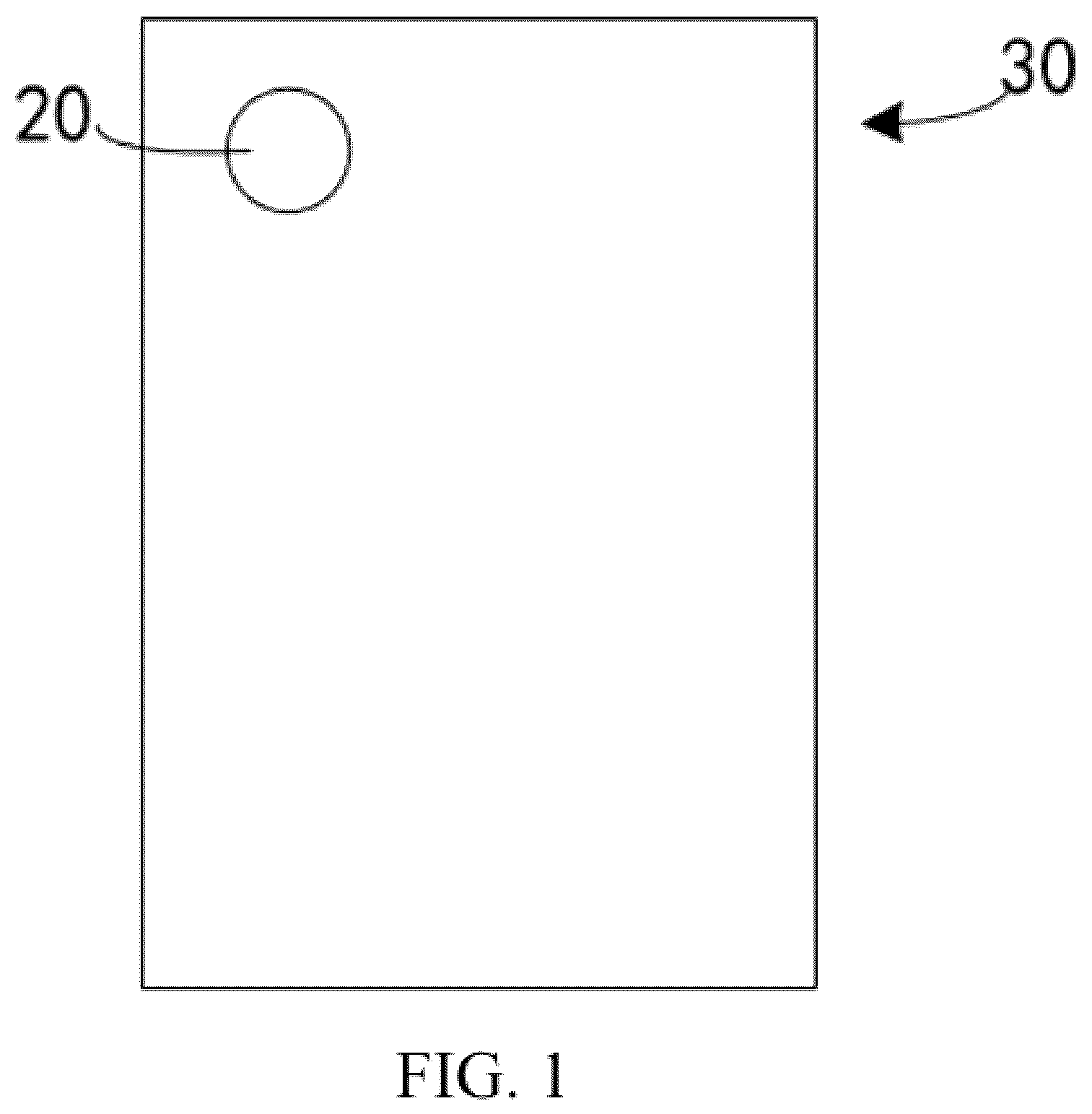
Referring to , an optical system in this disclosure is applicable in a lens module 20 of a terminal device 30 . The terminal device 30 may be a mobile phone, a tablet computer, a drone, a computer, and other types of devices. A photosensitive element of the lens module 20 is located at an image side of the optical system, and the lens module 20 is assembled in the terminal device 30 .
In this disclosure, a lens module is provided. The lens module includes a photosensitive element and the optical system according to the implementations of the disclosure. The photosensitive element is located at the image side of the optical system. The photosensitive element is configured to convert a ray, which passes through the first to seventh lenses and is incident on the photosensitive element, to an electrical signal of an image. The photosensitive element may be a complementary metal oxide semiconductor (CMOS) or a charge-coupled device (CCD). Through installation of the optical system in the lens module, the lens module can have characteristics of wide-angle imaging and compact size as well as good imaging quality.
In this disclosure, a terminal device is provided. The terminal device includes the lens module in implementations of this disclosure. The terminal device can be a mobile phone, a tablet computer, a drone, a computer, and other types of devices. Through the installation of the lens module in the terminal device, the terminal device can have characteristics of wide-angle imaging and compact size as well as good imaging quality.
In this disclosure, an optical system is provided. The optical system includes seven lenses, i.e., a first lens, a second lens, a third lens, a fourth lens, a fifth lens, a sixth lens, and a seventh lens, arranged in order from an object side to an image side of the optical system.
The surface profile and the refractive power of each of the seven lenses can be set as follows. The first lens has a positive refractive power, where the first lens has an object-side surface which is convex at an optical axis. The second lens has a refractive power, where the second lens has an object-side surface which is convex at the optical axis. The third lens has a refractive power, where the third lens has an image-side surface which is convex at the optical axis. The fourth lens has a refractive power. The fifth lens has a positive refractive power, where the fifth lens has an image-side surface which is convex at the optical axis. The sixth lens has a refractive power. The seventh lens has a refractive power, where the seventh lens has an object-side surface which is convex at the optical axis and an image-side surface which is concave at the optical axis. At least one of the object-side surface or the image-side surface of the seventh lens has an inflection point. The optical system satisfies the expressions tan ω/f>0.21 and Y2/Y1+Y3/Y1+Y4/Y1<3.1, where tan ω represents a tangential value of half of a maximum angle of view of the optical system, f represents an effective focal length of the optical system, Y1 represents an optical maximum effective radius of the object-side surface of the first lens, Y2 represents an optical maximum effective radius of the object-side surface of the second lens, Y3 represents an optical maximum effective radius of an object-side surface of the third lens, and Y4 represents an optical maximum effective radius of an object-side surface of the fourth lens.
Through proper arrangement of the refractive power of each of the first lens to the seventh lens and the surface profile of each of the first lens, the second lens, the third lens, the fifth lens, and the seventh lens and setting of tan ω/f>0.21mm −1 and Y2/Y1+Y3/Y1+Y4/Y1<3.1, the optical system has characteristics of compact size and wide-angle imaging. Through the setting of the inflection point, the excessive increase of an angle of incident ray of off-axis field of view can be suppressed, which can effectively correct aberration and reduce distortion to improve the imaging quality.
Through controlling the optical maximum effective radius of each of the first lens, the second lens, the third lens, and the fourth lens, the optical system can have a small forward end aperture and a small head shape, which satisfies the demand for the compact size of the optical system. If Y2/Y1+Y3/Y1+Y4/Y1≥3.1, any aperture of the first lens, the second lens, the third lens, and the fourth lens is relatively large, so that the entire volume of the forward end of the optical system will become larger, which is not beneficial to the realization of the compact size of the optical system. Through proper arrangement of a range of tan ω/f, the optical system has the characteristic of wide-angle imaging. If tan ω/f≤0.21, the angle of view will become smaller and a range of the captured image will become narrower on the condition that the focal length is the same.
In some implementations, the optical system satisfies the expression 1<f1/f<1.6, where f represents an effective focal length of the optical system and f1 represents a focal length of the first lens. Through the proper arrangement of the range of a ratio of f1/f, field curvature of the optical system can be corrected and the high imaging quality can be ensured. In addition, the effective focal length of the optical system can be reasonably shortened, which facilitates the shortening of a total length of the optical system, so that the optical system has the characteristic of compact size.
In some implementations, the optical system satisfies the expression f12/f34>−0.54, where f12 represents a combined focal length of the first lens and the second lens, and f34 represents a combined focal length of the third lens and the fourth lens. The combined lens of the first lens and the second lens provides the positive refractive power. The combined lens of the third lens and the fourth lens provides the negative refractive power, which can facilitate the correction of spherical aberration generated by the first lens and the second lens. When f12/f34>−0.54, the optical system can have the high imaging quality. When f12/f34<−0.54, the combined focal length of the first lens and the second lens becomes larger and the positive power smaller, which is not beneficial to the improvement of the imaging quality.
In some implementations, the optical system satisfies the expression 1.66<n4<1.69, where n4 represents a refractive index of the fourth lens. The fourth lens has a high refractive index, which can improve a modulation transfer function of the optical system to realize a better systematic performance and correct chromatic aberration to ensure the imaging quality
In some implementations, the optical system satisfies the expression 0.5<f/f5<1.4, where f represents an effective focal length of the optical system and f5 represents a focal length of the fifth lens. The first lens provides most of the positive refractive power for imaging. The fifth lens compensates the first lens and provides the positive refractive power together with the first lens to improve the imaging quality.
In some implementations, the optical system satisfies the expression 3.7<f/CT5<5.1, where f represents an effective focal length of the optical system and CTS represents a thickness of the fifth lens on the optical axis. The fifth lens has the positive refractive power. Through the proper arrangement of the thickness of the fifth lens on the optical axis, the total length of the optical system can be effectively shortened to facilitate the realization of the compact size of the optical system.
In some implementations, the optical system satisfies the expression TTL/EPD<2.8, where TTL represents a distance on the optical axis from the object-side surface of the first lens to an imaging surface of the optical system, and EPD represents an entrance pupil diameter of the optical system. Generally, the optical system with seven-piece lens will be configured with the bigger entrance pupil diameter to increase an amount of passed light. Through the proper arrangement of the ratio of TTL/EPD, the total length of the optical system can be effectively shortened to facilitate the realization of the compact size of the optical system.
In some implementations, the optical system satisfies the expression FNO/ImgH≤0.55 mm −1 , where FNO represents an F-number of the optical system, and ImgH represents half of a diagonal length of an effective pixel area on an imaging surface of the optical system. Through defining the proper range of FNO/ImgII, the optical system can have the large aperture to improve the imaging quality.
The optical system is provided with aspheric lenses to facilitate the aberration correction of the optical system and improve the imaging quality of the optical system. Equations which apply to aspheric curves include but are not limited to the following expression:
Z = c r 2 1 + 1 - ( k + 1 ) c 2 r 2 + ∑ i Air i
Where Z represents a distance from a respective point on an aspheric surface to a plane tangent to a vertex of the aspheric surface, r represents a distance from the respective point on the aspheric surface to the optical axis, c represents a curvature of the vertex of the aspheric surface, k represents a conic coefficient, and Ai represents a coefficient corresponding to the i-th higher-order term in the aspheric equation.
Detailed description will be provided hereinafter, through eight implementations, to illustrate this disclosure.
In , a straight line 11 represent an optical axis. A side of a first lens L 1 away from a second lens L 2 is an object side 12 . A side of a seventh lens L 7 away from a sixth lens L 6 is an image side 13 . An optical system of this implementation includes, from the object side 12 to the image side 13 , a stop STO, the first lens L 1 , the second lens L 2 , a third lens L 3 , a fourth lens L 4 , a fifth lens L 5 , the sixth lens L 6 , the seventh lens L 7 , and an infrared cut-off filter (IRCF). At least one of an object-side surface or an image-side surface of the seventh lens L 7 has an inflection point.
The first lens L 1 with a positive refractive power is made of plastic. An object-side surface S 1 is convex at the optical axis and at a periphery. An image-side surface S 2 is concave at the optical axis and convex at the periphery. Both the object-side surface S 1 and the image-side surface S 2 of the first lens L 1 are aspheric.
The second lens L 2 with a positive refractive power is made of plastic. An object-side surface S 3 is concave at the optical axis and at the periphery. An image-side surface S 4 is convex at the optical axis and at the periphery. Both the object-side surface S 3 and the image-side surface S 4 of the second lens L 2 are aspheric.
The third lens L 3 with a negative refractive power is made of plastic. An object-side surface S 5 is concave at the optical axis and at the periphery. An image-side surface S 6 is convex at the optical axis and at the periphery. Both the object-side surface S 5 and the image-side surface S 6 of the third lens L 3 are aspheric.
The fourth lens L 4 with a negative refractive power is made of plastic. An object-side surface S 7 is concave at the optical axis and at the periphery. An image-side surface S 8 is concave at the optical axis and convex at the periphery. Both the object-side surface S 7 and the image-side surface S 8 of the fourth lens L 4 are aspheric.
The fifth lens L 5 with a positive refractive power is made of plastic. An object-side surface S 9 is concave at the optical axis and at the periphery. An image-side surface S 10 is convex at the optical axis and at the periphery. Both the object-side surface S 9 and the image-side surface S 10 of the fifth lens L 5 are aspheric.
The sixth lens L 6 with a negative refractive power is made of plastic. An object-side surface S 11 is concave at the optical axis and at the periphery. An image-side surface S 12 is concave at the optical axis and convex at the periphery. Both the object-side surface S 11 and the image-side surface S 12 of the sixth lens L 6 are aspheric.
The seventh lens L 7 with a negative refractive power is made of plastic. An object-side surface S 13 is convex at the optical axis and at the periphery. An image-side surface S 14 is concave at the optical axis and convex at the periphery. Both the object-side surface S 13 and the image-side surface S 14 of the seventh lens L 7 are aspheric.
The stop STO may be located between the object side of the optical system and the seventh lens L 7 . In this implementation, the stop STO is disposed at one side of the first lens L 1 away from the second lens L 2 to control the amount of light passed.
The IRCF is disposed after the seventh lens L 7 . The IRCF has an object-side surface S 15 and an image-side surface S 16 . The IRCF is configured to filter out infrared light so that the light incident onto the imaging surface is visible light. Visible light has a wavelength ranging from 380 nm to 780 nm. The IRCF is made of glass.
An imaging surface S 17 is the surface where an image formed by the light of the photographed object after going through the optical system is located.
Table 1 a illustrates characteristics of the optical system in this implementation.
TABLE 1a
Implementation of
f = 3.565 mm, FNO = 1.98, FOV = 90°, TTL = 5.04 mm
Radius of Focal
Surface Surface Surface curvature Thickness Refractive Abbe length
number name type (mm) (mm) Material index number (mm)
Object Object spheric Infinity 446.049
surface surface
STO STO spheric Infinity −0.197
S1 First lens aspheric 1.881 0.432 plastic 1.539 52.860 4.686
S2 aspheric 6.727 0.147
S3 Second aspheric −22.902 0.352 plastic 1.535 55.790 9.313
S4 lens aspheric −4.125 0.124
S5 Third aspheric −4.423 0.220 plastic 1.659 21.220 −13.023
S6 lens aspheric −9.227 0.170
S7 Fourth aspheric −17.297 0.352 plastic 1.671 20.390 −13.383
S8 lens aspheric 19.183 0.212
S9 Fifth lens aspheric −5.003 0.750 plastic 1.578 34.300 2.659
S10 aspheric −1.246 0.095
S11 Sixth lens aspheric −5.855 0.306 plastic 1.671 20.390 −5.391
S12 aspheric 9.896 0.348
S13 Seventh aspheric 1.215 0.408 plastic 1.563 39.240 −6.543
S14 lens aspheric 0.804 0.506
S15 Infrared spheric Infinity 0.234 glass 1.517 64.167
S16 cut-off spheric Infinity 0.386
filter
S17 Imaging spheric Infinity 0.000
surface
Note:
a reference wavelength is 555 nm
In Table 1 a , f represents an effective focal length of the optical system, FNO represents an F-number of the optical system, FOV represents an angle of view of the optical system diagonally, and TTL represents a distance on the optical axis from the object-side surface of the first lens to the imaging surface of the optical system.
Table 1 b shows high-order coefficients A4, A6, A8, A10, A12, A14, A16, A18, and A20 which are applicable to each of the aspheric lens surfaces S 1 , S 2 , S 3 , S 4 , S 5 , S 6 , S 7 , S 8 , S 9 , S 10 , S 11 , and S 12 of the implementation of .
TABLE 1b
Implementation of
Aspheric coefficients
Surface
number S1 S2 S3 S4 S5 S6 S7
K −5.4635E−01 2.1177E+01 9.9000E+01 3.8413E+00 6.7267E−01 −2.9540E+00 9.9000E+01
A4 −1.0873E−03 −2.6947E−02 −4.3175E−02 −5.5636E−02 −1.5460E−02 1.1055E−02 −1.3355E−01
A6 −7.2443E−02 −2.5124E−01 −3.3378E−02 −1.7834E−02 2.7862E−01 −6.9698E−02 −2.1894E−02
A8 8.2285E−01 1.9177E+00 1.1413E−01 1.1703E−01 −2.2147E+00 3.5719E−01 −2.4512E−01
A10 −5.0089E+00 −9.5428E+00 −1.9767E−01 −3.3500E−01 9.9082E+00 −1.4683E+00 1.4509E+00
A12 1.6575E+01 2.8894E+01 1.7213E−01 5.3756E−01 −2.7255E+01 3.8535E+00 −4.8166E+00
A14 −3.2371E+01 −5.4270E+01 −1.5959E−02 −4.5899E−01 4.7116E+01 −5.9581E+00 9.3781E+00
A16 3.7028E+01 6.1446E+01 −1.3668E−02 1.5660E−01 −4.9938E+01 5.2251E+00 −1.0482E+01
A18 −2.2985E+01 −3.8285E+01 0.0000E+00 0.0000E+00 2.9623E+01 −2.3906E+00 6.2011E+00
A20 5.9809E+00 1.0080E+01 0.0000E+00 0.0000E+00 −7.5178E+00 4.4046E−01 −1.5008E+00
Surface
number S8 S9 S10 S11 S12 S13 S14
K −7.2615E+01 8.9781E+00 −2.8204E+00 −9.9000E+01 1.3007E+01 −7.6415E+00 −3.5620E+00
A4 −1.0099E−01 −1.1043E−01 −1.3372E−01 1.9050E−01 1.9848E−01 −2.2474E−02 −6.5706E−02
A6 −1.6942E−02 −6.9817E−02 2.5462E−01 −8.9014E−02 −1.8922E−01 −1.1306E−01 −8.1754E−03
A8 3.6410E−01 9.6642E−01 −4.3073E−01 −6.3446E−02 9.1394E−02 1.0154E−01 2.0629E−02
A10 −1.0168E+00 −2.1536E+00 5.5136E−01 9.9996E−02 −2.9585E−02 −4.8364E−02 −1.1205E−02
A12 1.4948E+00 2.6075E+00 −5.0263E−01 −6.3673E−02 6.3377E−03 1.4261E−02 3.2745E−03
A14 −1.3117E+00 −1.9606E+00 3.0465E−01 2.3915E−02 −8.2164E−04 −2.6125E−03 −5.6374E−04
A16 6.8851E−01 9.1760E−01 −1.1405E−01 −5.4132E−03 5.2914E−05 2.8784E−04 5.6834E−05
A18 −2.0080E−01 −2.4743E−01 2.3526E−02 6.7975E−04 −4.8057E−07 −1.7448E−05 −3.0959E−06
A20 2.5506E−02 2.9682E−02 −2.0138E−03 −3.6269E−05 −7.9295E−08 4.4710E−07 7.0228E−08
shows a longitudinal spherical aberration curve, an astigmatic curve, and a distortion curve of the optical system according to the implementation of . The longitudinal spherical aberration curve represents deviation in focal point of rays with different wavelengths after the rays go through the lenses of the optical system. The astigmatic curve represents tangential image plane bending and sagittal image plane bending. The distortion curve represents distortion values corresponding to different angles of view. As can be seen in , the optical system in the implementation of has high imaging quality.
In , a straight line 11 represents an optical axis. A side of a first lens L 1 away from a second lens L 2 is an object side 12 . A side of a seventh lens L 7 away from a sixth lens L 6 is an image side 13 . An optical system of this implementation includes, from the object side 12 to the image side 13 , a stop STO, the first lens L 1 , the second lens L 2 , a third lens L 3 , a fourth lens L 4 , a fifth lens L 5 , the sixth lens L 6 , the seventh lens L 7 , and an IRCF. At least one of an object-side surface or an image-side surface of the seventh lens L 7 has an inflection point.
The first lens L 1 with a positive refractive power is made of plastic. An object-side surface S 1 is convex at the optical axis and at a periphery. An image-side surface S 2 is concave at the optical axis and convex at the periphery. Both the object-side surface S 1 and the image-side surface S 2 of the first lens L 1 are aspheric.
The second lens L 2 with a positive refractive power is made of plastic. An object-side surface S 3 is concave at the optical axis and at the periphery. An image-side surface S 4 is convex at the optical axis and at the periphery. Both the object-side surface S 3 and the image-side surface S 4 of the second lens L 2 are aspheric.
The third lens L 3 with a negative refractive power is made of plastic. An object-side surface S 5 is concave at the optical axis and at the periphery. An image-side surface S 6 is convex at the optical axis and at the periphery. Both the object-side surface S 5 and the image-side surface S 6 of the third lens L 3 are aspheric.
The fourth lens L 4 with a negative refractive power is made of plastic. An object-side surface S 7 is concave at the optical axis and at the periphery. An image-side surface S 8 is concave at the optical axis and convex at the periphery. Both the object-side surface S 7 and the image-side surface S 8 of the fourth lens L 4 are aspheric.
The fifth lens L 5 with a positive refractive power is made of plastic. An object-side surface S 9 is concave at the optical axis and at the periphery. An image-side surface S 10 is convex at the optical axis and at the periphery. Both the object-side surface S 9 and the image-side surface S 10 of the fifth lens L 5 are aspheric.
The sixth lens L 6 with a negative refractive power is made of plastic. An object-side surface S 11 is concave at the optical axis and at the periphery. An image-side surface S 12 is concave at the optical axis and convex at the periphery. Both the object-side surface S 11 and the image-side surface S 12 of the sixth lens L 6 are aspheric.
The seventh lens L 7 with a negative refractive power is made of plastic. An object-side surface S 13 is convex at the optical axis and at the periphery. An image-side surface S 14 is concave at the optical axis and convex at the periphery. Both the object-side surface S 13 and the image-side surface S 14 of the seventh lens L 7 are aspheric.
The stop STO may be located between the object side of the optical system and the seventh lens L 7 . In this implementation, the stop STO is disposed at one side of the first lens L 1 away from the second lens L 2 to control the amount of light passed.
The IRCF is disposed after the seventh lens L 7 . The IRCF has an object-side surface S 15 and an image-side surface S 16 . The IRCF is configured to filter out the infrared light so that the light incident onto the imaging surface is visible light. Visible light has a wavelength ranging from 380 nm to 780 nm. The IRCF is made of glass.
An imaging surface S 17 is the surface where an image formed by the light of the photographed object after going through the optical system is located.
Table 2 a illustrates characteristics of the optical system in this implementation.
TABLE 2a
Implementation of
f = 3.43 mm, FNO = 1.85, FOV = 92.2°, TTL = 4.926 mm
Radius
of Thick- Re- Focal
Surface Surface Surface curvature ness fractive Abbe Length
number name type (mm) (mm) Material index number (mm)
Object Object spheric Infinity 450.509
surface surface
STO Stop spheric Infinity −0.209
S1 First lens aspheric 1.897 0.457 plastic 1.544 56.114 4.58
S2 aspheric 7.207 0.149
S3 Second aspheric −20.203 0.357 plastic 1.535 55.660 9.97
S4 lens aspheric −4.257 0.096
S5 Third aspheric −4.607 0.222 plastic 1.655 21.510 −15.97
S6 lens aspheric −8.335 0.187
S7 Fourth aspheric −16.021 0.285 plastic 1.670 20.510 −13.41
S8 lens aspheric 20.989 0.188
S9 Fifth lens aspheric −5.043 0.735 plastic 1.567 37.720 2.75
S10 aspheric −1.258 0.083
S11 Sixth lens aspheric −5.528 0.318 plastic 1.671 20.670 −5.25
S12 aspheric 10.005 0.328
S13 Seventh aspheric 1.191 0.414 plastic 1.534 55.770 −8.85
S14 lens aspheric 0.836 0.493
S15 Infrared spheric Infinity 0.237 glass 1.517 64.167
S16 cut-off spheric Infinity 0.377
filter
S17 Imaging spheric Infinity 0.000
surface
Note:
a reference wavelength is 555 nm
In Table 2 a , f represents an effective focal length of the optical system, FNO represents an F-number of the optical system, FOV represents an angle of view of the optical system diagonally, and TTL represents a distance on the optical axis from the object-side surface of the first lens to the imaging surface of the optical system.
Table 2 b shows high-order coefficients A4, A6, A8, A10, A12, A14, A16, A18, and A20 which are applicable to each of the aspheric lens surfaces S 1 , S 2 , S 3 , S 4 , S 5 , S 6 , S 7 , S 8 , S 9 , S 10 , S 11 , and S 12 of the implementation of .
TABLE 2b
Implementation of
Aspheric coefficients
Surface
number S1 S2 S3 S4 S5 S6 S7
K −5.3689E−01 2.0878E+01 9.6293E+01 3.0802E+00 5.0424E−01 −3.4866E−02 8.9688E+01
A4 6.3921E−04 −1.0081E−02 −3.8496E−02 −5.1517E−02 2.1258E−02 3.7470E−03 −1.1109E−01
A6 −1.6885E−01 −4.1839E−01 −1.5909E−01 −1.3782E−02 −3.3378E−01 −6.5919E−02 −2.3479E−01
A8 1.5894E+00 2.4711E+00 1.0358E+00 5.6641E−02 2.3770E+00 3.5709E−01 8.7223E−01
A10 −7.7578E+00 −8.9400E+00 −3.6048E+00 1.2766E−01 −9.8492E+00 −9.3915E−01 −2.0383E+00
A12 2.1347E+01 1.9732E+01 7.2464E+00 −1.0705E+00 2.5235E+01 1.3488E+00 2.5648E+00
A14 −3.5081E+01 −2.7111E+01 −8.2539E+00 2.5463E+00 −4.0402E+01 −9.8681E−01 −1.3458E+00
A16 3.4068E+01 2.2570E+01 4.8328E+00 −2.9744E+00 3.9292E+01 1.7390E−01 −4.2193E−01
A18 −1.8076E+01 −1.0389E+01 −9.3008E−01 1.7250E+00 −2.1220E+01 2.0198E−01 8.2208E−01
A20 4.0442E+00 2.0338E+00 −1.5362E−01 −3.9554E−01 4.8816E+00 −9.3593E−02 −2.6990E−01
Surface
number S8 S9 S10 S11 S12 S13 S14
K −9.8711E+01 8.7938E+00 −3.0442E+00 −9.9000E+01 1.3068E+01 −7.7362E+00 −3.8444E+00
A4 −1.0277E−01 −1.0609E−01 −1.0855E−01 2.0087E−01 2.0344E−01 −3.0309E−02 −5.8699E−02
A6 −4.3106E−02 −7.8549E−02 1.1087E−01 −1.1837E−01 −1.8946E−01 −8.4216E−02 −1.3442E−02
A8 3.0673E−01 8.8727E−01 −4.5295E−02 −1.7145E−02 8.5058E−02 7.7109E−02 2.3117E−02
A10 −5.9403E−01 −1.8811E+00 −2.8468E−02 5.0844E−02 −2.3649E−02 −3.6395E−02 −1.2158E−02
A12 6.4311E−01 2.2557E+00 2.0730E−02 −3.1143E−02 3.8317E−03 1.0439E−02 3.5186E−03
A14 −4.5154E−01 −1.7375E+00 2.0825E−02 1.0897E−02 −2.4445E−04 −1.8343E−03 −6.0175E−04
A16 2.1320E−01 8.4977E−01 −2.4776E−02 −2.3405E−03 −2.1733E−05 1.9207E−04 6.0373E−05
A18 −6.4216E−02 −2.4033E−01 9.0203E−03 2.8554E−04 4.5869E−06 −1.1002E−05 −3.2839E−06
A20 9.7438E−03 2.9917E−02 −1.1503E−03 −1.5058E−05 −2.1861E−07 2.6548E−07 7.4756E−08
shows a longitudinal spherical aberration curve, an astigmatic curve, and a distortion curve of the optical system according to the implementation of . The longitudinal spherical aberration curve represents deviation in focal point of rays with different wavelengths after the rays go through the lenses of the optical system. The astigmatic curve represents tangential image plane bending and sagittal image plane bending. The distortion curve represents distortion values corresponding to different angles of view. As can be seen in , the optical system in the implementation of has high imaging quality.
In , a straight line 11 represents an optical axis. A side of a first lens L 1 away from a second lens L 2 is an object side 12 . A side of a seventh lens L 7 away from a sixth lens L 6 is an image side 13 . An optical system of this implementation includes, from the object side 12 to the image side 13 , a stop STO, the first lens L 1 , the second lens L 2 , a third lens L 3 , a fourth lens L 4 , a fifth lens L 5 , the sixth lens L 6 , the seventh lens L 7 , and an IRCF. At least one of an object-side surface or an image-side surface of the seventh lens L 7 has an inflection point.
The first lens L 1 with a positive refractive power is made of plastic. An object-side surface S 1 is convex at the optical axis and at a periphery. An image-side surface S 2 is concave at the optical axis and convex at the periphery. Both the object-side surface S 1 and the image-side surface S 2 of the first lens L 1 are aspheric.
The second lens L 2 with a negative refractive power is made of plastic. An object-side surface S 3 is concave at the optical axis and at the periphery. An image-side surface S 4 is convex at the optical axis and at the periphery. Both the object-side surface S 3 and the image-side surface S 4 of the second lens L 2 are aspheric.
The third lens L 3 with a positive refractive power is made of plastic. An object-side surface S 5 is concave at the optical axis and at the periphery. An image-side surface S 6 is convex at the optical axis and at the periphery. Both the object-side surface S 5 and the image-side surface S 6 of the third lens L 3 are aspheric.
The fourth lens L 4 with a negative refractive power is made of plastic. An object-side surface S 7 is concave at the optical axis and at the periphery. An image-side surface S 8 is concave at the optical axis and convex at the periphery. Both the object-side surface S 7 and the image-side surface S 8 of the fourth lens L 4 are aspheric.
The fifth lens L 5 with a positive refractive power is made of plastic. An object-side surface S 9 is concave at the optical axis and at the periphery. An image-side surface S 10 is convex at the optical axis and at the periphery. Both the object-side surface S 9 and the image-side surface S 10 of the fifth lens L 5 are aspheric.
The sixth lens L 6 with a negative refractive power is made of plastic. An object-side surface S 11 is concave at the optical axis and at the periphery. An image-side surface S 12 is concave at the optical axis and convex at the periphery. Both the object-side surface S 11 and the image-side surface S 12 of the sixth lens L 6 are aspheric.
The seventh lens L 7 with a negative refractive power is made of plastic. An object-side surface S 13 is convex at the optical axis and concave at the periphery. An image-side surface S 14 is concave at the optical axis and convex at the periphery. Both the object-side surface S 13 and the image-side surface S 14 of the seventh lens L 7 are aspheric.
The stop STO may be located between the object side of the optical system and the seventh lens L 7 . In this implementation, the stop STO is disposed at one side of the first lens L 1 away from the second lens L 2 to control the amount of light passed.
The IRCF is disposed after the seventh lens L 7 . The IRCF has an object-side surface S 15 and an image-side surface S 16 . The IRCF is configured to filter out the infrared light so that the light incident onto the imaging surface is visible light. Visible light has a wavelength ranging from 380 nm to 780 nm. The IRCF is made of glass.
An imaging surface S 17 is the surface where an image formed by the light of the photographed object after going through the optical system is located.
Table 3 a illustrates characteristics of the optical system in this implementation.
TABLE 3a
Implementation of
f = 3.56mm, FNO = 1.8, FOV = 96°, TTL = 5.073 mm
Radius
of
curva- Thick- Re- Focal
Surface Surface Surface ture ness fractive Abbe length
number name type (mm) (mm) Material index number (mm)
Object Object spheric Infinity 4.00E+02
surface surface
STO Stop spheric Infinity −0.190
S1 First lens aspheric 2.086 0.485 plastic 1.544 56.114 4.61
S2 aspheric 11.203 0.215
S3 Second aspheric −12.629 0.221 plastic 1.537 53.770 −100.00
S4 lens aspheric −16.594 0.081
S5 Third lens aspheric −22.440 0.294 plastic 1.535 55.790 26.90
S6 aspheric −8.825 0.153
S7 Fourth lens aspheric −30.053 0.310 plastic 1.671 20.390 −15.36
S8 aspheric 15.961 0.213
S9 Fifth lens aspheric −6.053 0.709 plastic 1.557 39.650 3.33
S10 aspheric −1.484 0.080
S11 Sixth lens aspheric −7.352 0.313 plastic 1.671 20.390 −6.34
S12 aspheric 10.489 0.311
S13 Seventh aspheric 1.257 0.509 plastic 1.534 55.770 −10.12
S14 lens aspheric 0.877 0.559
S15 Infrared spheric Infinity 0.265 glass 1.517 64.167
S16 cut-off spheric Infinity 0.354
filter
S17 Imaging spheric Infinity 0.000
surface
Note:
a reference wavelength is 555 nm
In Table 3 a , f represents an effective focal length of the optical system, FNO represents an F-number of the optical system, FOV represents an angle of view of the optical system diagonally, and TTL represents a distance on the optical axis from the object-side surface of the first lens to the imaging surface of the optical system.
Table 3 b shows high-order coefficients A4, A6, A8, A10, A12, A14, A16, A18, and A20 which are applicable to each of the aspheric lens surfaces S 1 , S 2 , S 3 , S 4 , S 5 , S 6 , S 7 , S 8 , S 9 , S 10 , S 11 , and S 12 of the implementation of .
TABLE 3b
Implementation of
Aspheric coefficients
Surface
number S1 S2 S3 S4 S5 S6 S7
K −8.1085E−01 −2.0400E+01 9.7271E+01 2.5148E+01 1.8895E+01 3.1258E+00 9.9000E+01
A4 −1.0766E−02 −8.1923E−03 −2.6063E−02 −3.5054E−02 2.9264E−03 5.4085E−03 −9.1459E−02
A6 4.6334E−02 −2.2921E−01 −7.8459E−03 −1.2945E−02 −1.1292E−02 −3.2528E−03 8.1784E−02
A8 −5.0079E−02 1.1912E+00 4.3199E−02 1.1454E−01 −3.9999E−02 −2.1814E−01 −1.0636E+00
A10 −6.2527E−01 −3.9521E+00 2.4462E−02 −2.5688E−01 3.3185E−01 1.0723E+00 4.1022E+00
A12 2.7057E+00 8.1877E+00 −1.9692E−01 2.7188E−01 −8.4338E−01 −2.4367E+00 −8.7022E+00
A14 −5.1910E+00 −1.0819E+01 2.0672E−01 −1.7772E−01 1.0265E+00 3.1462E+00 1.1104E+01
A16 5.3334E+00 8.8131E+00 −7.4333E−02 4.9681E−02 −5.7376E−01 −2.3669E+00 −8.5013E+00
A18 −2.8629E+00 −4.0262E+00 0.0000E+00 0.0000E+00 7.2025E−02 9.6445E−01 3.5933E+00
A20 6.3120E−01 7.8727E−01 0.0000E+00 0.0000E+00 3.5244E−02 −1.6391E−01 −6.4315E−01
Surface
number S8 S9 S10 S11 S12 S13 S14
K 8.1430E+01 1.0696E+01 −3.1648E+00 −8.2841E+01 1.0054E+01 −6.9660E+00 −3.8519E+00
A4 −6.2348E−02 −8.6712E−02 −1.2318E−01 1.9996E−01 1.7207E−01 −4.2275E−02 −4.1781E−02
A6 −2.0184E−02 3.3710E−02 2.0758E−01 −1.2859E−01 −1.2288E−01 −2.7353E−02 −3.5658E−03
A8 −1.2612E−01 1.2134E−01 −2.6961E−01 2.8808E−02 3.6004E−02 2.1806E−02 8.0341E−03
A10 6.1893E−01 −7.4623E−02 2.5137E−01 −3.1573E−04 −4.0157E−03 −8.6494E−03 −3.8047E−03
A12 −1.1391E+00 −1.5235E−01 −1.5913E−01 −1.4119E−03 −6.4969E−04 2.1783E−03 9.4669E−04
A14 1.1338E+00 2.4988E−01 6.3455E−02 3.6739E−04 2.8883E−04 −3.3881E−04 −1.3673E−04
A16 −6.4768E−01 −1.5720E−01 −1.4027E−02 −5.5346E−05 −4.1497E−05 3.1176E−05 1.1490E−05
A18 2.0005E−01 4.7750E−02 1.3354E−03 7.0532E−06 2.8114E−06 −1.5542E−06 −5.2018E−07
A20 −2.5779E−02 −5.8207E−03 −1.4468E−05 −5.1066E−07 −7.5684E−08 3.2363E−08 9.7853E−09
shows a longitudinal spherical aberration curve, an astigmatic curve, and a distortion curve of the optical system according to the implementation of . The longitudinal spherical aberration curve represents deviation in focal point of rays with different wavelengths after the rays go through the lenses of the optical system. The astigmatic curve represents tangential image plane bending and sagittal image plane bending. The distortion curve represents distortion values corresponding to different angles of view. As can be seen in , the optical system in the implementation of has high imaging quality.
In , a straight line 11 represents an optical axis. A side of a first lens L 1 away from a second lens L 2 is an object side 12 . A side of a seventh lens L 7 away from a sixth lens L 6 is an image side 13 . An optical system of this implementation includes, from the object side 12 to the image side 13 , a stop STO, the first lens L 1 , the second lens L 2 , a third lens L 3 , a fourth lens L 4 , a fifth lens L 5 , the sixth lens L 6 , the seventh lens L 7 , and an IRCF. At least one of an object-side surface or an image-side surface of the seventh lens L 7 has an inflection point.
The first lens L 1 with a positive refractive power is made of plastic. An object-side surface S 1 is convex at the optical axis and at a periphery. An image-side surface S 2 is concave at the optical axis and convex at the periphery. Both the object-side surface S 1 and the image-side surface S 2 of the first lens L 1 are aspheric.
The second lens L 2 with a positive refractive power is made of plastic. An object-side surface S 3 is concave at the optical axis and at the periphery. An image-side surface S 4 is convex at the optical axis and at the periphery. Both the object-side surface S 3 and the image-side surface S 4 of the second lens L 2 are aspheric.
The third lens L 3 with a negative refractive power is made of plastic. An object-side surface S 5 is concave at the optical axis and at the periphery. An image-side surface S 6 is convex at the optical axis and at the periphery. Both the object-side surface S 5 and the image-side surface S 6 of the third lens L 3 are aspheric.
The fourth lens L 4 with a positive refractive power is made of plastic. An object-side surface S 7 is concave at the optical axis and at the periphery. An image-side surface S 8 is convex at the optical axis and at the periphery. Both the object-side surface S 7 and the image-side surface S 8 of the fourth lens L 4 are aspheric.
The fifth lens L 5 with a positive refractive power is made of plastic. An object-side surface S 9 is concave at the optical axis and at the periphery. An image-side surface S 10 is convex at the optical axis and at the periphery. Both the object-side surface S 9 and the image-side surface S 10 of the fifth lens L 5 are aspheric.
The sixth lens L 6 with a negative refractive power is made of plastic. An object-side surface S 11 is concave at the optical axis and at the periphery. An image-side surface S 12 is concave at the optical axis and convex at the periphery. Both the object-side surface S 11 and the image-side surface S 12 of the sixth lens L 6 are aspheric.
The seventh lens L 7 with a negative refractive power is made of plastic. An object-side surface S 13 is convex at the optical axis and concave at the periphery. An image-side surface S 14 is concave at the optical axis and convex at the periphery. Both the object-side surface S 13 and the image-side surface S 14 of the seventh lens L 7 are aspheric.
The stop STO may be located between the object side of the optical system and the seventh lens L 7 . In this implementation, the stop STO is disposed at one side of the first lens L 1 away from the second lens L 2 to control the amount of light passed.
The IRCF is disposed after the seventh lens L 7 . The IRCF has an object-side surface S 15 and an image-side surface S 16 . The IRCF is configured to filter out the infrared light so that the light incident onto the imaging surface is visible light. Visible light has a wavelength ranging from 380 nm to 780 nm. The IRCF is made of glass.
An imaging surface S 17 is the surface where an image formed by the light of the photographed object after going through the optical system is located.
Table 4 a illustrates characteristics of the optical system in this implementation.
TABLE 4a
Implementation of
f = 3.9 mm, FNO = 1.75, FOV = 91°, TTL = 5.411 mm
Radius
of Thick- Re- Focal
Surface Surface Surface curvature ness fractive Abbe Length
number name type (mm) (mm) Material index number (mm)
Object Object spheric Infinity 5.02E+02
surface surface
STO Stop spheric Infinity −0.249
S1 First lens aspheric 2.093 0.526 plastic 1.544 56.114 4.62
S2 aspheric 11.226 0.189
S3 Second aspheric −12.677 0.389 plastic 1.535 55.790 11.77
S4 lens aspheric −4.262 0.094
S5 Third aspheric −4.602 0.220 plastic 1.671 20.390 −13.85
S6 lens aspheric −9.213 0.175
S7 Fourth aspheric −26.768 0.290 plastic 1.671 20.390 96.35
S8 lens aspheric −19.062 0.243
S9 Fifth lens aspheric −3.863 0.892 plastic 1.573 35.910 3.20
S10 aspheric −1.352 0.080
S11 Sixth lens aspheric −4.516 0.378 plastic 1.671 20.390 −4.69
S12 aspheric 11.077 0.308
S13 Seventh aspheric 1.440 0.474 plastic 1.534 55.770 −6.80
S14 lens aspheric 0.913 0.545
S15 Infrared spheric Infinity 0.264 glass 1.517 64.167
S16 cut-off spheric Infinity 0.344
filter
S17 Imaging spheric Infinity 0.000
surface
Note:
a reference wavelength is 555 nm
In Table 4 a , f represents an effective focal length of the optical system, FNO represents an F-number of the optical system, FOV represents an angle of view of the optical system diagonally, and TTL represents a distance on the optical axis from the object-side surface of the first lens to the imaging surface of the optical system.
Table 4 b shows high-order coefficients A4, A6, A8, A10, A12, A14, A16, A18, and A20 which are applicable to each of the aspheric lens surfaces S 1 , S 2 , S 3 , S 4 , S 5 , S 6 , S 7 , S 8 , S 9 , S 10 , S 11 , and S 12 of the implementation of .
TABLE 4b
Implementation of
Aspheric coefficients
Surface
number S1 S2 S3 S4 S5 S6 S7
K −6.2616E−01 2.1015E+01 8.7010E+01 4.3530E+00 7.2692E−02 2.4025E−02 −9.7216E+01
A4 4.0033E−03 −2.0574E−02 −3.0696E−02 −3.3562E−02 1.3336E−03 4.9028E−03 −8.6760E−02
A6 −1.1137E−01 −1.3021E−01 −4.0204E−02 −6.6760E−02 1.8750E−02 −1.7125E−02 −7.0786E−02
A8 7.0776E−01 6.5259E−01 1.8894E−01 2.8592E−01 −2.7290E−01 −1.9715E−02 3.4352E−01
A10 −2.5438E+00 −2.0753E+00 −4.0331E−01 −5.6730E−01 1.2702E+00 2.1705E−01 −1.1307E+00
A12 5.2637E+00 4.0189E+00 4.8112E−01 5.9686E−01 −3.0257E+00 −5.0523E−01 2.2609E+00
A14 −6.5602E+00 −4.8484E+00 −3.0010E−01 −3.2808E−01 4.1209E+00 5.7850E−01 −2.8197E+00
A16 4.8445E+00 3.5522E+00 7.8169E−02 7.3828E−02 −3.2510E+00 −3.5734E−01 2.1040E+00
A18 −1.9555E+00 −1.4478E+00 0.0000E+00 0.0000E+00 1.3852E+00 1.1315E−01 −8.5006E−01
A20 3.3267E−01 2.5329E−01 0.0000E+00 0.0000E+00 −2.4690E−01 −1.4253E−02 1.4311E−01
Surface
number S8 S9 S10 S11 S12 S13 S14
K 9.1335E+01 7.7234E+00 −3.2458E+00 −2.8897E+01 1.2769E+01 −7.8109E+00 −4.0327E+00
A4 −6.1108E−02 −8.8376E−02 −9.1355E−02 1.6144E−01 1.5242E−01 −6.0160E−02 −5.5101E−02
A6 −1.9691E−01 −9.2995E−02 1.3867E−01 −7.3254E−02 −1.2157E−01 −9.3298E−03 8.2926E−03
A8 9.4927E−01 7.4110E−01 −1.2801E−01 −3.9116E−02 4.6369E−02 1.9155E−02 3.0001E−03
A10 −2.2287E+00 −1.4459E+00 4.7604E−02 5.6095E−02 −1.0667E−02 −9.7708E−03 −2.2039E−03
A12 3.1946E+00 1.6377E+00 2.2383E−02 −3.0040E−02 1.4197E−03 2.6443E−03 5.6993E−04
A14 −2.9051E+00 −1.1757E+00 −3.3293E−02 9.3315E−03 −8.4315E−05 −4.1222E−04 −7.8718E−05
A16 1.6176E+00 5.1425E−01 1.5511E−02 −1.7536E−03 −2.1653E−06 3.7154E−05 6.1504E−06
A18 −4.9929E−01 −1.2179E−01 −3.4050E−03 1.8507E−04 5.6767E−07 −1.8037E−06 −2.5601E−07
A20 6.5167E−02 1.1544E−02 2.9695E−04 −8.4033E−06 −2.2081E−08 3.6578E−08 4.4041E−09
shows a longitudinal spherical aberration curve, an astigmatic curve, and a distortion curve of the optical system according to the implementation of . The longitudinal spherical aberration curve represents deviation in focal point of rays with different wavelengths after the rays go through the lenses of the optical system. The astigmatic curve represents tangential image plane bending and sagittal image plane bending. The distortion curve represents distortion values corresponding to different angles of view. As can be seen in , the optical system in the implementation of has high imaging quality.
In , a straight line 11 represents an optical axis. A side of a first lens L 1 away from a second lens L 2 is an object side 12 . A side of a seventh lens L 7 away from a sixth lens L 6 is an image side 13 . An optical system of this implementation includes, from the object side 12 to the image side 13 , a stop STO, the first lens L 1 , the second lens L 2 , a third lens L 3 , a fourth lens L 4 , a fifth lens L 5 , the sixth lens L 6 , the seventh lens L 7 , and an IRCF. At least one of an object-side surface or an image-side surface of the seventh lens L 7 has an inflection point.
The first lens L 1 with a positive refractive power is made of plastic. An object-side surface S 1 is convex at the optical axis and at a periphery. An image-side surface S 2 is concave at the optical axis and convex at the periphery. Both the object-side surface S 1 and the image-side surface S 2 of the first lens L 1 are aspheric.
The second lens L 2 with a positive refractive power is made of plastic. An object-side surface S 3 is concave at the optical axis and at the periphery. An image-side surface S 4 is convex at the optical axis and at the periphery. Both the object-side surface S 3 and the image-side surface S 4 of the second lens L 2 are aspheric.
The third lens L 3 with a negative refractive power is made of plastic. An object-side surface S 5 is concave at the optical axis and at the periphery. An image-side surface S 6 is convex at the optical axis and at the periphery. Both the object-side surface S 5 and the image-side surface S 6 of the third lens L 3 are aspheric.
The fourth lens L 4 with a negative refractive power is made of plastic. An object-side surface S 7 is concave at the optical axis and at the periphery. An image-side surface S 8 is convex at the optical axis and at the periphery. Both the object-side surface S 7 and the image-side surface S 8 of the fourth lens L 4 are aspheric.
The fifth lens L 5 with a positive refractive power is made of plastic. An object-side surface S 9 is concave at the optical axis and at the periphery. An image-side surface S 10 is convex at the optical axis and at the periphery. Both the object-side surface S 9 and the image-side surface S 10 of the fifth lens L 5 are aspheric.
The sixth lens L 6 with a positive refractive power is made of plastic. An object-side surface S 11 is convex at the optical axis and concave at the periphery. An image-side surface S 12 is concave at the optical axis and convex at the periphery. Both the object-side surface S 11 and the image-side surface S 12 of the sixth lens L 6 are aspheric.
The seventh lens L 7 with a negative refractive power is made of plastic. An object-side surface S 13 is convex at the optical axis and concave at the periphery. An image-side surface S 14 is concave at the optical axis and convex at the periphery. Both the object-side surface S 13 and the image-side surface S 14 of the seventh lens L 7 are aspheric.
The stop STO may be located between the object side of the optical system and the seventh lens L 7 . In this implementation, the stop STO is disposed at one side of the first lens L 1 away from the second lens L 2 to control the amount of light passed.
The IRCF is disposed after the seventh lens L 7 . The IRCF includes an object-side surface S 15 and an image-side surface S 16 . The IRCF is configured to filter out the infrared light so that the light incident onto the imaging surface is visible light. Visible light has a wavelength ranging from 380 nm to 780 nm. The IRCF is made of glass.
An imaging surface S 17 is the surface where an image formed by the light of the photographed object after going through the optical system is located.
Table 5 a illustrates the characteristics of the optical system in this implementation.
TABLE 5a
Implementation of
f = 4.1 mm, FNO = 1.75, FOV = 87.7°, TTL = 5.72 mm
Radius
of Thick- Focal
Surface Surface Surface curvature ness Refractive Abbe length
number name type (mm) (mm) Material index number (mm)
Object Object spheric Infinity 5.22E+02
surface surface
STO Stop spheric Infinity −0.261
S1 First lens aspheric 2.196 0.540 plastic 1.544 56.114 4.88
S2 aspheric 11.369 0.226
S3 Second aspheric −13.036 0.392 plastic 1.535 55.790 11.16
S4 lens aspheric −4.146 0.108
S5 Third aspheric −4.323 0.220 plastic 1.671 20.390 −11.97
S6 lens aspheric −9.458 0.222
S7 Fourth aspheric −15.623 0.276 plastic 1.671 20.390 −76.29
S8 lens aspheric −22.559 0.239
S9 Fifth lens aspheric −4.285 0.859 plastic 1.540 52.100 8.14
S10 aspheric −2.325 0.080
S11 Sixth lens aspheric 11.687 0.428 plastic 1.671 20.390 109.78
S12 aspheric 13.663 0.446
S13 Seventh aspheric 1.705 0.503 plastic 1.534 55.770 −6.31
S14 lens aspheric 1.017 0.565
S15 Infrared spheric Infinity 0.274 glass 1.517 64.167
S16 cut-off spheric Infinity 0.341
filter
S17 Imaging spheric Infinity 0.000
surface
Note:
a reference wavelength is 555 nm
In Table 5 a , f represents an effective focal length of the optical system, FNO represents an F-number of the optical system, FOV represents an angle of view of the optical system diagonally, and TTL represents a distance on the optical axis from the object-side surface of the first lens to the imaging surface of the optical system.
Table 5 b shows high-order coefficients A4, A6, A8, A10, A12, A14, A16, A18, and A20 which are applicable to each of the aspheric lens surfaces S 1 , S 2 , S 3 , S 4 , S 5 , S 6 , S 7 , S 8 , S 9 , S 10 , S 11 , and S 12 of the implementation of .
TABLE 5b
Implementation of
Aspheric coefficients
Surface
number S1 S2 S3 S4 S5 S6 S7
K −5.7536E−01 2.3527E+01 9.3456E+01 3.9551E+00 2.0977E−02 −1.7962E−01 −1.3208E+01
A4 1.2735E−03 −1.6394E−02 −2.7636E−02 −2.9238E−02 1.4193E−03 3.1488E−03 −7.6860E−02
A6 −6.1942E−02 −1.0665E−01 −2.5605E−02 −6.3603E−02 2.8680E−03 −1.5044E−02 −1.1646E−01
A8 3.8637E−01 4.8506E−01 6.8624E−02 2.7993E−01 −1.0982E−01 1.3316E−02 4.1138E−01
A10 −1.3421E+00 −1.4001E+00 −1.0770E−02 −6.5094E−01 5.6058E−01 6.6305E−02 −9.0654E−01
A12 2.6258E+00 2.4527E+00 −2.2399E−01 9.4891E−01 −1.3601E+00 −2.1780E−01 1.2437E+00
A14 −3.0620E+00 −2.6765E+00 4.3669E−01 −9.0660E−01 1.8476E+00 2.9500E−01 −1.0904E+00
A16 2.1000E+00 1.7773E+00 −3.6703E−01 5.5513E−01 −1.4410E+00 −2.1269E−01 5.9026E−01
A18 −7.8332E−01 −6.5796E−01 1.4665E−01 −1.9956E−01 6.0367E−01 8.0307E−02 −1.7832E−01
A20 1.2272E−01 1.0470E−01 −2.2045E−02 3.2142E−02 −1.0535E−01 −1.2542E−02 2.3139E−02
Surface
number S8 S9 S10 S11 S12 S13 S14
K 6.8563E+01 8.1154E+00 −1.9931E+00 −9.9000E+01 1.2250E+01 −7.5863E+00 −3.4453E+00
A4 −5.8233E−02 −6.2803E−02 −1.0761E−01 1.0230E−01 1.7291E−01 −4.9925E−02 −5.8464E−02
A6 −1.1983E−01 −2.3202E−02 1.2668E−01 −4.3354E−02 −1.2557E−01 −1.7377E−02 1.3277E−02
A8 5.0995E−01 3.6698E−01 −8.8563E−02 −1.5427E−02 4.5138E−02 1.8278E−02 −1.0311E−03
A10 −9.9890E−01 −6.8079E−01 2.0254E−02 1.9492E−02 −9.9666E−03 −7.9970E−03 −5.3916E−04
A12 1.1746E+00 6.8487E−01 1.8813E−02 −8.3500E−03 1.3268E−03 2.0540E−03 1.9183E−04
A14 −8.7919E−01 −4.2879E−01 −1.8551E−02 2.0301E−03 −9.5130E−05 −3.1333E−04 −2.8178E−05
A16 4.0883E−01 1.6538E−01 7.2283E−03 −2.9675E−04 2.1926E−06 2.7853E−05 2.1911E−06
A18 −1.0727E−01 −3.5634E−02 −1.3810E−03 2.4416E−05 1.2119E−07 −1.3354E−06 −8.8535E−08
A20 1.2128E−02 3.2409E−03 1.0615E−04 −8.6961E−07 −6.3428E−09 2.6735E−08 1.4654E−09
shows a longitudinal spherical aberration curve, an astigmatic curve, and a distortion curve of the optical system according to the implementation of . The longitudinal spherical aberration curve represents deviation in focal point of rays with different wavelengths after the rays go through the lenses of the optical system. The astigmatic curve represents tangential image plane bending and sagittal image plane bending. The distortion curve represents distortion values corresponding to different angles of view. As can be seen in , the optical system in the implementation of has high imaging quality.
In , a straight line 11 represents an optical axis. A side of a first lens L 1 away from a second lens L 2 is an object side 12 . A side of a seventh lens L 7 away from a sixth lens L 6 is an image side 13 . An optical system of this implementation includes, from the object side 12 to the image side 13 , a stop STO, the first lens L 1 , the second lens L 2 , a third lens L 3 , a fourth lens L 4 , a fifth lens L 5 , the sixth lens L 6 , the seventh lens L 7 , and an IRCF. At least one of an object-side surface or an image-side surface of the seventh lens L 7 has an inflection point.
The first lens L 1 with a positive refractive power is made of plastic. An object-side surface S 1 is convex at the optical axis and at a periphery. An image-side surface S 2 is concave at the optical axis and convex at the periphery. Both the object-side surface S 1 and the image-side surface S 2 of the first lens L 1 are aspheric.
The second lens L 2 with a positive refractive power is made of plastic. An object-side surface S 3 is concave at the optical axis and at the periphery. An image-side surface S 4 is convex at the optical axis and at the periphery. Both the object-side surface S 3 and the image-side surface S 4 of the second lens L 2 are aspheric.
The third lens L 3 with a negative refractive power is made of plastic. An object-side surface S 5 is concave at the optical axis and at the periphery. An image-side surface S 6 is convex at the optical axis and at the periphery. Both the object-side surface S 5 and the image-side surface S 6 of the third lens L 3 are aspheric.
The fourth lens L 4 with a negative refractive power is made of plastic. An object-side surface S 7 is concave at the optical axis and at the periphery. An image-side surface S 8 is concave at the optical axis and convex at the periphery. Both the object-side surface S 7 and the image-side surface S 8 of the fourth lens L 4 are aspheric.
The fifth lens L 5 with a positive refractive power is made of plastic. An object-side surface S 9 is concave at the optical axis and at the periphery. An image-side surface S 10 is convex at the optical axis and at the periphery. Both the object-side surface S 9 and the image-side surface S 10 of the fifth lens L 5 are aspheric.
The sixth lens L 6 with a negative refractive power is made of plastic. An object-side surface S 11 is concave at the optical axis and at the periphery. An image-side surface S 12 is concave at the optical axis and convex at the periphery. Both the object-side surface S 11 and the image-side surface S 12 of the sixth lens L 6 are aspheric.
The seventh lens L 7 with a positive refractive power is made of plastic. An object-side surface S 13 is convex at the optical axis and at the periphery. An image-side surface S 14 is concave at the optical axis and convex at the periphery. Both the object-side surface S 13 and the image-side surface S 14 of the seventh lens L 7 are aspheric.
The stop STO may be located between the object side of the optical system and the seventh lens L 7 . In this implementation, the stop STO is disposed at one side of the first lens L 1 away from the second lens L 2 to control the amount of light passed.
The IRCF is disposed after the seventh lens L 7 . The IRCF includes an object-side surface S 15 and an image-side surface S 16 . The IRCF is configured to filter out the infrared light so that the light incident onto the imaging surface is visible light. Visible light has a wavelength ranging from 380 nm to 780 nm. The IRCF is made of glass.
An imaging surface S 17 is the surface where an image formed by the light of the photographed object after going through the optical system is located.
Table 6 a illustrates the characteristics of the optical system in this implementation.
TABLE 6a
Implementation of
f = 3.338 mm, FNO = 1.8, FOV = 100°, TTL = 5.23 mm
Radius
of Thick- Focal
Surface Surface Surface curvature ness Refractive Abbe length
number name type (mm) (mm) Material index number (mm)
Object Object spheric Infinity 5.54E+02
surface surface
STO Stop spheric Infinity −0.167
S1 First lens aspheric 2.239 0.451 plastic 1.544 56.114 5.26
S2 aspheric 9.451 0.233
S3 Second aspheric −13.378 0.387 plastic 1.535 55.790 8.00
S4 lens aspheric −3.285 0.080
S5 Third aspheric −3.402 0.220 plastic 1.671 20.390 −7.95
S6 lens aspheric −9.487 0.185
S7 Fourth aspheric −30.807 0.220 plastic 1.671 20.390 −33.29
S8 lens aspheric 84.233 0.193
S9 Fifth lens aspheric −5.666 0.902 plastic 1.535 55.750 3.17
S10 aspheric −1.381 0.080
S11 Sixth lens aspheric −3.756 0.285 plastic 1.544 56.114 −5.01
S12 aspheric 10.309 0.100
S13 Seventh aspheric 0.951 0.506 plastic 1.559 41.180 29.88
S14 lens aspheric 0.816 0.767
S15 Infrared spheric Infinity 0.291 glass 1.517 64.167
S16 cut-off spheric Infinity 0.329
filter
S17 Imaging spheric Infinity 0.000
surface
Note:
a reference wavelength is 555 nm
In Table 6 a , f represents an effective focal length of the optical system, FNO represents an F-number of the optical system, FOV represents an angle of view of the optical system diagonally, and TTL represents a distance on the optical axis from the object-side surface of the first lens to the imaging surface of the optical system.
Table 6 b shows high-order coefficients A4, A6, A8, A10, A12, A14, A16, A18, and A20 which are applicable to each of the aspheric lens surfaces S 1 , S 2 , S 3 , S 4 , S 5 , S 6 , S 7 , S 8 , S 9 , S 10 , S 11 , and S 12 of the implementation of .
TABLE 6b
Implementation of
Aspheric coefficients
Surface
number S1 S2 S3 S4 S5 S6 S7
K −1.2075E+00 −9.9000E+01 9.9000E+01 2.5966E+00 7.7200E−01 1.2674E+01 −8.6772E+01
A4 6.5245E−04 7.8082E−03 −2.0254E−02 −9.9469E−03 6.0212E−14 −5.6509E−03 −3.4034E−02
A6 −5.6644E−02 −2.3788E−01 −1.4293E−01 −1.1505E−01 −1.2146E−12 3.8013E−02 −2.0853E−01
A8 9.9965E−01 1.1301E+00 6.7509E−01 4.5081E−01 8.7387E−12 −6.9900E−02 6.3400E−01
A10 −6.3784E+00 −3.6566E+00 −2.4841E+00 −9.9110E−01 −3.1717E−11 −6.6236E−02 −1.6158E+00
A12 2.0851E+01 7.3202E+00 6.1612E+00 1.4341E+00 6.5724E−11 3.7616E−01 2.5426E+00
A14 −3.9345E+01 −9.5754E+00 −9.8880E+00 −1.4132E+00 −8.1244E−11 −5.3381E−01 −2.4186E+00
A16 4.3184E+01 8.0970E+00 9.7497E+00 9.6654E−01 5.9297E−11 3.7392E−01 1.4044E+00
A18 −2.5646E+01 −4.0801E+00 −5.3522E+00 −4.3105E−01 −2.3589E−11 −1.3422E−01 −4.6870E−01
A20 6.3727E+00 9.3218E−01 1.2483E+00 9.0795E−02 3.9442E−12 1.9940E−02 6.9308E−02
Surface
number S8 S9 S10 S11 S12 S13 S14
K 9.9000E+01 7.9116E+00 −2.3106E+00 −8.8521E+01 5.6345E+00 −4.5587E+00 −2.7809E+00
A4 −1.3048E−02 −3.2175E−02 −1.3171E−01 1.4715E−01 1.6380E−01 4.0702E−02 −2.6248E−02
A6 −1.0110E−01 −5.7919E−02 2.3628E−01 −3.7425E−02 −1.0497E−01 −8.9570E−02 −1.8399E−02
A8 2.2176E−01 3.0356E−01 −3.2033E−01 −3.1562E−02 4.0088E−02 4.7631E−02 1.3290E−02
A10 −3.9399E−01 −4.2704E−01 3.0016E−01 2.9739E−02 −1.1823E−02 −1.3416E−02 −4.1130E−03
A12 4.1925E−01 2.9147E−01 −1.9357E−01 −1.2784E−02 2.6708E−03 2.2505E−03 7.2064E−04
A14 −2.5179E−01 −9.8290E−02 8.4832E−02 3.2625E−03 −4.2807E−04 −2.3120E−04 −7.5443E−05
A16 8.4174E−02 9.7637E−03 −2.4640E−02 −4.9470E−04 4.4151E−05 1.4268E−05 4.6711E−06
A18 −1.4633E−02 2.9134E−03 4.3556E−03 4.0850E−05 −2.5762E−06 −4.8575E−07 −1.5772E−07
A20 1.0543E−03 −6.5410E−04 −3.5197E−04 −1.4089E−06 6.4059E−08 7.0107E−09 2.2364E−09
shows a longitudinal spherical aberration curve, an astigmatic curve, and a distortion curve of the optical system according to the implementation of . The longitudinal spherical aberration curve represents deviation in focal point of rays with different wavelengths after the rays go through the lenses of the optical system. The astigmatic curve represents tangential image plane bending and sagittal image plane bending. The distortion curve represents distortion values corresponding to different angles of view. As can be seen in , the optical system in the implementation of has high imaging quality.
In , a straight line 11 represents an optical axis. A side of a first lens L 1 away from a second lens L 2 is an object side 12 . A side of a seventh lens L 7 away from a sixth lens L 6 is an image side 13 . An optical system of this implementation includes, from the object side 12 to the image side 13 , a stop STO, the first lens L 1 , the second lens L 2 , a third lens L 3 , a fourth lens L 4 , a fifth lens L 5 , the sixth lens L 6 , the seventh lens L 7 , and an IRCF. At least one of an object-side surface or an image-side surface of the seventh lens L 7 has an inflection point.
The first lens L 1 with a positive refractive power is made of plastic. An object-side surface S 1 is convex at the optical axis and at a periphery. An image-side surface S 2 is concave at the optical axis and convex at the periphery. Both the object-side surface S 1 and the image-side surface S 2 of the first lens L 1 are aspheric.
The second lens L 2 with a positive refractive power is made of plastic. An object-side surface S 3 is concave at the optical axis and at the periphery. An image-side surface S 4 is convex at the optical axis and at the periphery. Both the object-side surface S 3 and the image-side surface S 4 of the second lens L 2 are aspheric.
The third lens L 3 with a negative refractive power is made of plastic. An object-side surface S 5 is concave at the optical axis and at the periphery. An image-side surface S 6 is convex at the optical axis and at the periphery. Both the object-side surface S 5 and the image-side surface S 6 of the third lens L 3 are aspheric.
The fourth lens L 4 with a negative refractive power is made of plastic. An object-side surface S 7 is concave at the optical axis and at the periphery. An image-side surface S 8 is convex at the optical axis and at the periphery. Both the object-side surface S 7 and the image-side surface S 8 of the fourth lens L 4 are aspheric.
The fifth lens L 5 with a positive refractive power is made of plastic. An object-side surface S 9 is concave at the optical axis and at the periphery. An image-side surface S 10 is convex at the optical axis and at the periphery. Both the object-side surface S 9 and the image-side surface S 10 of the fifth lens L 5 are aspheric.
The sixth lens L 6 with a negative refractive power is made of plastic. An object-side surface S 11 is concave at the optical axis and at the periphery. An image-side surface S 12 is concave at the optical axis and convex at the periphery. Both the object-side surface S 11 and the image-side surface S 12 of the sixth lens L 6 are aspheric.
The seventh lens L 7 with a positive refractive power is made of plastic. An object-side surface S 13 is convex at the optical axis and concave at the periphery. An image-side surface S 14 is concave at the optical axis and convex at the periphery. Both the object-side surface S 13 and the image-side surface S 14 of the seventh lens L 7 are aspheric.
The stop STO may be located between the object side of the optical system and the seventh lens L 7 . In this implementation, the stop STO is disposed at one side of the first lens L 1 away from the second lens L 2 to control the amount of light passed.
The IRCF is disposed after the seventh lens L 7 . The IRCF includes an object-side surface S 15 and an image-side surface S 16 . The IRCF is configured to filter out the infrared light so that the light incident onto the imaging surface is visible light. Visible light has a wavelength ranging from 380 nm to 780 nm. The IRCF is made of glass.
An imaging surface S 17 is the surface where an image formed by the light of the photographed object after going through the optical system is located.
Table 7 a illustrates the characteristics of the optical system in this implementation.
TABLE 7a
Implementation of
f = 3.835 mm, FNO = 1.75, FOV = 92°, TTL = 5.81 mm
Radius
of Thick- Re- Focal
Surface Surface Surface curvature ness fractive Abbe length
number name type (mm) (mm) Material index number (mm)
Object Object spheric Infinity 5.94E+02
surface surface
STO Stop spheric Infinity −0.190
S1 First lens aspheric 2.453 0.531 plastic 1.544 56.114 5.47
S2 aspheric 12.688 0.333
S3 Second aspheric −13.198 0.396 plastic 1.538 53.200 8.56
S4 lens aspheric −3.459 0.086
S5 Third aspheric −3.622 0.220 plastic 1.658 21.310 −8.44
S6 lens aspheric −10.514 0.184
S7 Fourth aspheric −23.930 0.287 plastic 1.671 20.390 −42.94
S8 lens aspheric −136.004 0.219
S9 Fifth lens aspheric −5.341 0.891 plastic 1.536 54.610 3.79
S10 aspheric −1.561 0.081
S11 Sixth lens aspheric −5.194 0.375 plastic 1.545 48.350 −5.68
S12 aspheric 7.934 0.217
S13 Seventh aspheric 1.098 0.587 plastic 1.534 55.770 100.00
S14 lens aspheric 0.911 0.778
S15 Infrared spheric Infinity 0.312 glass 1.517 64.167
S16 cut-off spheric Infinity 0.311
filter
S17 Imaging spheric Infinity 0.000
surface
Note:
a reference wavelength is 555 nm
In Table 7 a , f represents an effective focal length of the optical system, FNO represents an F-number of the optical system, FOV represents an angle of view of the optical system diagonally, and TTL represents a distance on the optical axis from the object-side surface of the first lens to the imaging surface of the optical system.
Table 7 b shows high-order coefficients A4, A6, A8, A10, A12, A14, A16, A18, and A20 which are applicable to each of the aspheric lens surfaces S 1 , S 2 , S 3 , S 4 , S 5 , S 6 , S 7 , S 8 , S 9 , S 10 , S 11 , and S 12 of the implementation of .
TABLE 7b
Implementation of
Aspheric coefficients
Surface
number S1 S2 S3 S4 S5 S6 S7
K −1.1586E+00 −9.8195E+01 9.8946E+01 3.3599E+00 0.0000E+00 0.0000E+00 9.9000E+01
A4 2.9552E−03 −1.5657E−02 −1.2122E−02 −6.3762E−03 0.0000E+00 0.0000E+00 −6.9728E−02
A6 −2.6786E−02 1.5487E−02 −6.4701E−02 −1.1233E−01 0.0000E+00 0.0000E+00 1.3441E−01
A8 1.4371E−01 −2.2980E−01 6.7600E−02 4.6501E−01 0.0000E+00 0.0000E+00 −6.7174E−01
A10 −5.1655E−01 8.2127E−01 2.2143E−01 −1.3094E+00 0.0000E+00 0.0000E+00 1.4574E+00
A12 1.0084E+00 −1.6668E+00 −1.0056E+00 2.4295E+00 0.0000E+00 0.0000E+00 −1.9039E+00
A14 −1.1642E+00 1.9729E+00 1.7810E+00 −2.8485E+00 0.0000E+00 0.0000E+00 1.5942E+00
A16 7.8100E−01 −1.3573E+00 −1.6780E+00 2.0226E+00 0.0000E+00 0.0000E+00 −8.3500E−01
A18 −2.8099E−01 5.0338E−01 8.2955E−01 −7.9294E−01 0.0000E+00 0.0000E+00 2.4806E−01
A20 4.1594E−02 −7.7973E−02 −1.7005E−01 1.3123E−01 0.0000E+00 0.0000E+00 −3.1852E−02
Surface
number S8 S9 S10 S11 S12 S13 S14
K 9.9000E+01 8.5899E+00 −2.3774E+00 −9.9000E+01 −7.6169E+00 −4.5344E+00 −2.9698E+00
A4 −3.1159E−02 −5.0270E−02 −8.1489E−02 1.3055E−01 8.1602E−02 −1.1040E−03 −1.8515E−02
A6 7.2667E−02 5.1594E−02 1.4067E−01 −4.3666E−02 −2.4537E−02 −3.9172E−02 −1.5203E−02
A8 −2.7580E−01 2.8820E−02 −1.8514E−01 −6.0973E−03 −1.0661E−03 2.0503E−02 1.0317E−02
A10 4.2098E−01 −1.1734E−01 1.6386E−01 1.0141E−02 2.0373E−03 −5.4806E−03 −3.1713E−03
A12 −3.7679E−01 1.2428E−01 −9.9935E−02 −4.4828E−03 −5.4099E−04 8.6542E−04 5.5602E−04
A14 2.1643E−01 −7.0327E−02 4.0715E−02 1.1222E−03 7.4541E−05 −8.2231E−05 −5.8187E−05
A16 −7.8231E−02 2.3478E−02 −1.0515E−02 −1.6544E−04 −5.9209E−06 4.5531E−06 3.5933E−06
A18 1.6019E−02 −4.4749E−03 1.5605E−03 1.3261E−05 2.6017E−07 −1.3201E−07 −1.2079E−07
A20 −1.3979E−03 3.8444E−04 −1.0122E−04 −4.4399E−07 −4.9791E−09 1.4635E−09 1.7027E−09
shows a longitudinal spherical aberration curve, an astigmatic curve, and a distortion curve of the optical system according to the implementation of . The longitudinal spherical aberration curve represents deviation in focal point of rays with different wavelengths after the rays go through the lenses of the optical system. The astigmatic curve represents tangential image plane bending and sagittal image plane bending. The distortion curve represents distortion values corresponding to different angles of view. As can be seen in , the optical system in the implementation of has high imaging quality.
In , a straight line 11 represents an optical axis. A side of a first lens L 1 away from a second lens L 2 is an object side 12 . A side of a seventh lens L 7 away from a sixth lens L 6 is an image side 13 . An optical system of this implementation includes, from the object side 12 to the image side 13 , a stop STO, the first lens L 1 , the second lens L 2 , a third lens L 3 , a fourth lens L 4 , a fifth lens L 5 , the sixth lens L 6 , the seventh lens L 7 , and an IRCF. At least one of an object-side surface or an image-side surface of the seventh lens L 7 has an inflection point.
The first lens L 1 with a positive refractive power is made of plastic. An object-side surface S 1 is convex at the optical axis and at a periphery. An image-side surface S 2 is concave at the optical axis and at the periphery. Both the object-side surface S 1 and the image-side surface S 2 of the first lens L 1 are aspheric.
The second lens L 2 with a positive refractive power is made of plastic. An object-side surface S 3 is convex at the optical axis and at the periphery. An image-side surface S 4 is convex at the optical axis and at the periphery. Both the object-side surface S 3 and the image-side surface S 4 of the second lens L 2 are aspheric.
The third lens L 3 with a negative refractive power is made of plastic. An object-side surface S 5 is concave at the optical axis and at the periphery. An image-side surface S 6 is convex at the optical axis and at the periphery. Both the object-side surface S 5 and the image-side surface S 6 of the third lens L 3 are aspheric.
The fourth lens L 4 with a negative refractive power is made of plastic. An object-side surface S 7 is convex at the optical axis and concave at the periphery. An image-side surface S 8 is concave at the optical axis and at the periphery. Both the object-side surface S 7 and the image-side surface S 8 of the fourth lens L 4 are aspheric.
The fifth lens L 5 with a positive refractive power is made of plastic. An object-side surface S 9 is concave at the optical axis and at the periphery. An image-side surface S 10 is convex at the optical axis and at the periphery. Both the object-side surface S 9 and the image-side surface S 10 of the fifth lens L 5 are aspheric.
The sixth lens L 6 with a negative refractive power is made of plastic. An object-side surface S 11 is concave at the optical axis and at the periphery. An image-side surface S 12 is concave at the optical axis and convex at the periphery. Both the object-side surface S 11 and the image-side surface S 12 of the sixth lens L 6 are aspheric.
The seventh lens L 7 with a negative refractive power is made of plastic. An object-side surface S 13 is convex at the optical axis and concave at the periphery. An image-side surface S 14 is concave at the optical axis and convex at the periphery. Both the object-side surface S 13 and the image-side surface S 14 of the seventh lens L 7 are aspheric.
The stop STO may be located between the object side of the optical system and the seventh lens L 7 . In this implementation, the stop STO is disposed at one side of the first lens L 1 away from the second lens L 2 to control the amount of light passed.
The IRCF is disposed after the seventh lens L 7 . The IRCF includes an object-side surface S 15 and an image-side surface S 16 . The IRCF is configured to filter out infrared light so that the light incident onto the imaging surface is visible light. Visible light has a wavelength ranging from 380 nm to 780 nm. The IRCF is made of glass.
An imaging surface S 17 is the surface where an image formed by the light of the photographed object after going through the optical system is located.
Table 8 a illustrates the characteristics of the optical system in this implementation.
TABLE 8a
Implementation of
f = 4.25 mm, FNO = 1.85, FOV = 85°, TTL = 5.91 mm
Radius
of Thick- Re- Focal
Surface Surface Surface curvature ness fractive Abbe length
number name type (mm) (mm) Material index number (mm)
Object Object spheric Infinity 5.66E+02
surface surface
STO Stop spheric Infinity −0.279
S1 First aspheric 2.264 0.473 plastic 1.544 56.114 6.79
S2 lens aspheric 5.387 0.214
S3 Second aspheric 10.867 0.516 plastic 1.535 55.790 7.49
S4 lens aspheric −6.274 0.090
S5 Third aspheric −6.128 0.232 plastic 1.671 20.390 −23.48
S6 lens aspheric −10.126 0.219
S7 Fourth aspheric 12.781 0.379 plastic 1.671 20.390 −12.33
S8 lens aspheric 4.989 0.323
S9 Fifth aspheric −15.881 1.000 plastic 1.585 30.620 3.23
S10 lens aspheric −1.738 0.083
S11 Sixth aspheric −5.539 0.465 plastic 1.667 20.740 −6.22
S12 lens aspheric 17.701 0.268
S13 Seventh aspheric 1.807 0.517 plastic 1.534 55.770 −5.97
S14 lens aspheric 1.040 0.534
S15 Infrared spheric Infinity 0.297 glass 1.517 64.167
S16 cut-off spheric Infinity 0.298
filter
S17 Imaging spheric Infinity 0.000
surface
Note:
a reference wavelength is 555 nm
In Table 8 a , f represents an effective focal length of the optical system, FNO represents an F-number of the optical system, FOV represents an angle of view of the optical system diagonally, and TTL represents a distance on the optical axis from the object-side surface of the first lens to the imaging surface of the optical system.
Table 8 b shows high-order coefficients A4, A6, A8, A10, A12, A14, A16, A18, and A20 which are applicable to each of the aspheric lens surfaces S 1 , S 2 , S 3 , S 4 , S 5 , S 6 , S 7 , S 8 , S 9 , S 10 , S 11 , and S 12 of the implementation of .
TABLE 8b
Implementation of
Aspheric coefficients
Surface
number S1 S2 S3 S4 S5 S6 S7
K −4.6362E−01 1.7837E+01 7.0675E+01 7.1502E+00 −6.3777E−02 2.6040E−01 8.9113E+01
A4 −3.7612E−03 −1.2876E−02 −2.7960E−02 −2.1138E−02 1.1210E−03 −2.3648E−03 −7.7492E−02
A6 −2.4704E−02 −1.0205E−01 1.5350E−03 −1.4978E−01 −3.2111E−02 −1.6366E−03 −4.3249E−02
A8 2.1672E−01 4.8857E−01 8.8199E−02 7.6861E−01 2.8456E−01 1.2351E−01 2.7455E−01
A10 −8.2779E−01 −1.4159E+00 −3.9944E−01 −2.2149E+00 −1.1058E+00 −5.4384E−01 −7.5380E−01
A12 1.6905E+00 2.5234E+00 8.6097E−01 3.8850E+00 2.2841E+00 1.0913E+00 1.1182E+00
A14 −2.0128E+00 −2.8088E+00 −1.0393E+00 −4.2161E+00 −2.7067E+00 −1.2064E+00 −9.7123E−01
A16 1.3970E+00 1.8892E+00 7.1596E−01 2.7629E+00 1.8509E+00 7.5867E−01 4.9032E−01
A18 −5.2491E−01 −7.0115E−01 −2.6361E−01 −1.0024E+00 −6.7988E−01 −2.5480E−01 −1.3207E−01
A20 8.2536E−02 1.0994E−01 4.0605E−02 1.5487E−01 1.0392E−01 3.5545E−02 1.4556E−02
Surface
number S8 S9 S10 S11 S12 S13 S14
K 2.7521E+00 3.3702E+01 −3.4070E+00 −1.2251E+01 1.4528E+01 −1.0190E+01 −4.2237E+00
A4 −9.4832E−02 −8.3360E−02 −8.0711E−02 1.2131E−01 1.5031E−01 −6.0268E−02 −5.8135E−02
A6 1.4911E−01 7.7100E−02 1.5398E−01 −2.9677E−02 −1.1024E−01 1.9480E−03 1.5300E−02
A8 −2.3008E−01 6.5333E−02 −1.8541E−01 −5.9290E−02 3.9271E−02 5.2434E−03 −1.8964E−03
A10 2.3891E−01 −2.3590E−01 1.3389E−01 5.6557E−02 −8.6773E−03 −2.0053E−03 −5.6938E−04
A12 −1.6710E−01 2.7787E−01 −6.2968E−02 −2.6798E−02 1.2060E−03 3.5232E−04 2.7551E−04
A14 7.7894E−02 −1.8359E−01 1.9817E−02 7.9746E−03 −1.0583E−04 −2.9696E−05 −4.7604E−05
A16 −2.3424E−02 7.1963E−02 −3.9499E−03 −1.5050E−03 6.0787E−06 7.5925E−07 4.1965E−06
A18 4.0821E−03 −1.5742E−02 4.3524E−04 1.6421E−04 −2.4376E−07 4.1193E−08 −1.8823E−07
A20 −2.9368E−04 1.4860E−03 −1.9239E−05 −7.8415E−06 5.7863E−09 −2.1488E−09 3.4081E−09
shows a longitudinal spherical aberration curve, an astigmatic curve, and a distortion curve of the optical system according to the implementation of . The longitudinal spherical aberration curve represents deviation in focal point of rays with different wavelengths after the rays go through the lenses of the optical system. The astigmatic curve represents tangential image plane bending and sagittal image plane bending. The distortion curve represents distortion values corresponding to different angles of view. As can be seen in , the optical system in the implementation of has high imaging quality.
Table 9 shows the values of tan ω/f, f/f5, f1/f, TTL/EPD,f12/f34, n4, FNO/ImgH, f/CT5, and Y2/Y1+Y3/Y1+Y4/Y1 of the optical system of the above implementations.
TABLE 9
tanω/f f/f5 f1/f TTL/EPD f12/f34
Implementation of .281 1.341 1.314 2.774 −0.511
2
Implementation of .303 1.247 1.335 2.636 −0.465
4
Implementation of .312 1.069 1.295 2.537 −0.133
6
Implementation of .261 1.219 1.185 2.406 −0.215
8
Implementation of .234 0.504 1.190 2.420 −0.351
10
Implementation of .357 1.053 1.576 1.372 −0.538
12
Implementation of .270 1.012 1.426 2.634 −0.517
14
Implementation of .216 1.316 1.598 2.547 −0.484
16
Y2/Y1 + Y3/Y1 +
n4 FNO/ImgH f/CT5 Y4/Y1
Implementation of .671 0.550 4.753 3.022
2
Implementation of .670 0.514 4.667 3.035
4
Implementation of .671 0.450 5.021 3.058
6
Implementation of .671 0.438 4.372 3.027
8
Implementation of .671 0.438 4.773 2.950
10
Implementation of .671 0.450 3.701 3.571
12
Implementation of .671 0.438 4.304 3.087
14
Implementation of .671 0.463 4.250 3.087
16
As can be seen in Table 9, each of these implementations satisfies the expressions tan ω/f>0.21 mm−1, 0.5<f/f5<1.4, 1<f1/f<1.6, TTL/EPD<2.8, f12/f34>−0.54, 1.66<n4<1.69, FNO/ImgH≤0.55 mm−1, 3.7<f/CT5<5.1, Y2/Y1+Y3/Y1+Y4/Y1<3.1.
The implementations are described as above. It should be noted that any modifications, or improvements that can be made by those skilled in the art without departing from the spirits and principles of this disclosure shall all be encompassed within the protection of this disclosure.
Figures (17)
Citations
This patent cites (13)
- US20180106984
- US20190154972
- US20190204555
- US20190369359
- US20190369360
- US20190369367
- US20200041770
- US108089317
- US108254864
- US109683294
- US109960014
- US110031956
- US210051916