Lens Barrel and Camera Equipped with Same
Abstract
It is an object of the present disclosure to provide a lens barrel with which looseness caused by a gap formed between a fixed barrel and a cam barrel can be effectively suppressed without increasing the rotational torque of the cam barrel, as well as a camera equipped with this lens barrel. A lens barrel 100 comprises first to seventh lens group units 21 to 27 , a substantially cylindrical rectilinear barrel 11 , a substantially cylindrical cam barrel 12 , and spacers 11 ga, 11 gb, 11 ha, 11 hb, 11 ia and 11 ib . The cam barrel 12 moves the third to seventh lens group units 23 to 27 in the optical axis OP direction by being rotated with respect to the rectilinear barrel 11 in a state in which main cam followers 11 b and main cam grooves 12 b are engaged with each other. The spacers 11 ga, 11 gb, 11 ha, 11 hb, 11 ia and 11 ib protrude in the radial direction from the rectilinear barrel 11 and come into contact with the cam barrel 12 so as to suppress looseness between the rectilinear barrel 11 and the cam barrel 12 , and the length in the optical axis OP direction is equal to or greater than the amount of movement of the cam barrel 12 in the optical axis OP direction with respect to the rectilinear barrel 11.
Claims (14)
1. A lens barrel, comprising: at least one lens group; a substantially cylindrical fixed barrel that holds the lens group on an inner peripheral surface side and has a cam barrel cam follower that protrudes in a radial direction; a substantially cylindrical cam barrel that is disposed substantially coaxially with the fixed barrel, has a cam groove that is formed along a direction intersecting an optical axis direction and engages with the cam barrel cam follower in order to move the lens group in the optical axis direction, and moves the lens groups in the optical axis direction by being rotated relative to the fixed barrel in a state in which the cam barrel cam follower and the cam groove are engaged with each other; and a spacer that protrudes in the radial direction from the fixed barrel and comes into contact with the cam barrel so as to suppress looseness in the radial direction between the fixed barrel and the cam barrel, a length of the spacer in the optical axis direction being equal to or greater than an amount of movement of the cam barrel in the optical axis direction with respect to the fixed barrel.
Show 13 dependent claims
2. The lens barrel according to claim 1 , wherein the cam barrel is disposed on an outer peripheral side of the fixed barrel, and has a sliding surface on its inner peripheral side over which the spacer slides in a state of contact, and the sliding surface is smaller than an inside diameter of a portion of the cam barrel other than the sliding surface.
3. The lens barrel according to claim 1 , wherein the spacer includes a first spacer and a second spacer disposed one ahead of the other along the optical axis direction.
4. The lens barrel according to claim 3 , wherein the first spacer is disposed near a first end portion of the fixed barrel on a subject side in the optical axis direction, and the second spacer is disposed near a second end portion of the fixed barrel on an image plane side in the optical axis direction, which is on an opposite side from the first end portion.
5. The lens barrel according to claim 4 , wherein the cam barrel respectively has a first sliding surface on a side of the first end portion, and a second sliding surface on a side of the second end portion, on the inner peripheral surface side thereof, and the first spacer is always in contact with the first sliding surface, and the second spacer is always in contact with the second sliding surface, respectively, within a range in which the cam barrel moves in the optical axis direction.
6. The lens barrel according to claim 3 , wherein at least one of the first spacer and the second spacer have a length that is greater than a length of the maximum amount of movement of the cam barrel with respect to the rectilinear barrel in the optical axis direction.
7. The lens barrel according to claim 1 , wherein the fixed barrel has a recess in which the spacer is attached.
8. The lens barrel according to claim 7 , wherein the spacer is removably attached in the recess.
9. The lens barrel according to claim 8 , wherein the spacer includes a removable spacer that is removably attached in the recess and a fixed spacer that is molded integrally with the fixed barrel.
10. The lens barrel according to claim 1 , wherein the spacer has a substantially rounded shape on a surface that comes into contact with the cam barrel.
11. The lens barrel according to claim 1 , wherein the spacer is formed so that a curvature of a surface that comes into contact with the cam barrel is less than a curvature of the sliding surface.
12. The lens barrel according to claim 1 , wherein a plurality of the spacers are disposed at specific angular intervals in a circumferential direction around the optical axis.
13. The lens barrel according to claim 12 , wherein the spacers are provided on an outer peripheral surface of the fixed barrel at intervals of approximately 120 degrees, and support the inner peripheral surface of the cam barrel at three points.
14. A camera, comprising: the lens barrel according to claim 1 ; and a camera body to which the lens barrel is attached.
Full Description
Show full text →
CROSS-REFERENCE TO RELATED APPLICATIONS
This application claims priority to Japanese Patent Application No. 2021-039852 filed on Mar. 12, 2021. The entire disclosure of Japanese Patent Application No. 2021-039852 is hereby incorporated herein by reference.
BACKGROUND
Technical Field
The present disclosure relates to a lens barrel mounted on a camera body, and to a camera equipped with this lens barrel.
Description of the Related Art
A lens barrel mounted on a camera body comprises a plurality of frames that support an optical system. The first frame body included in this plurality of frame bodies has a cam member, and the second frame body has a guide groove in which the cam member is inserted and slides.
When the first and second frames rotate relative to each other, the cam member is guided by the guide groove, and as the frames move relative to each other in the optical axis direction, the result is a retractable lens barrel.
For example, Patent Literature 1 discloses a lens barrel comprising a fixed barrel having a guide groove, a cam barrel that is disposed rotatably with respect to the fixed barrel and has a cam groove having a tapered portion, and a moving lens holding member that holds a moving lens and that movably holds a cam follower that moves along the guide groove, wherein the cam follower has a tapered contact portion that can come into contact with the tapered portion of the cam groove, and is biased outward in the radial direction by a cam follower biasing member.
CITATION LIST
Patent Literature
•
• Patent Literature 1: International Laid-Open Patent Application No. 2014/136162 • Patent Literature 2: JP 2005-274704 • Patent Literature 3: JP 2015-040971
SUMMARY
However, the following problems are encountered with the conventional lens barrel described above.
Specifically, with the lens barrel disclosed in the above publication, the cam follower is outward in the radial direction to reduce the risk that the cam follower will come out of the cam groove, or that the cam follower or the cam groove will be deformed, if the lens barrel should be subjected to an impact force. However, with a configuration such as this, the cam follower is pressed against the tapered portion of the cam groove by the biasing force of a spring or the like, so a problem is that rotational torque tends to be high, among other problems.
In particular, with a configuration in which a plurality of lens groups are driven in the optical axis direction, the lens frames that hold the lens groups driven by the rotation of the cam barrel will be heavy, so problems such as rotational torque are more likely to occur.
It is an object of the present disclosure to provide a lens barrel with which looseness caused by a gap formed between a fixed barrel and a cam barrel can be effectively suppressed without increasing the rotational torque of the cam barrel, as well as a camera equipped with this lens barrel
The lens barrel according to the present disclosure includes one or more lens groups, a substantially cylindrical fixed barrel, a substantially cylindrical cam barrel, and a spacer. The substantially cylindrical fixed barrel holds the lens group on the inner peripheral surface side and has a cam follower that protrudes in the radial direction. The substantially cylindrical cam barrel is disposed substantially coaxially with the fixed barrel, has a cam groove that is formed in a direction intersecting the optical axis direction and engages with the cam barrel cam follower in order to move the lens group in the optical axis direction, and moves the lens groups in the optical axis direction by being rotated relative to the fixed barrel in a state in which the cam barrel cam follower and the cam groove are engaged with each other. The spacer protrudes in the radial direction from the fixed barrel and comes into contact with the cam barrel so as to suppress looseness in the radial direction between the fixed barrel and the cam barrel, the length of the spacer in the optical axis direction being equal to or greater than the amount of movement of the cam barrel in the optical axis direction with respect to the fixed barrel.
Effects
With the lens barrel according to the present disclosure, it is possible to effectively suppress looseness caused by a gap formed between the fixed barrel and the cam barrel, without increasing the rotational torque of the cam barrel.
BRIEF DESCRIPTION OF DRAWINGS
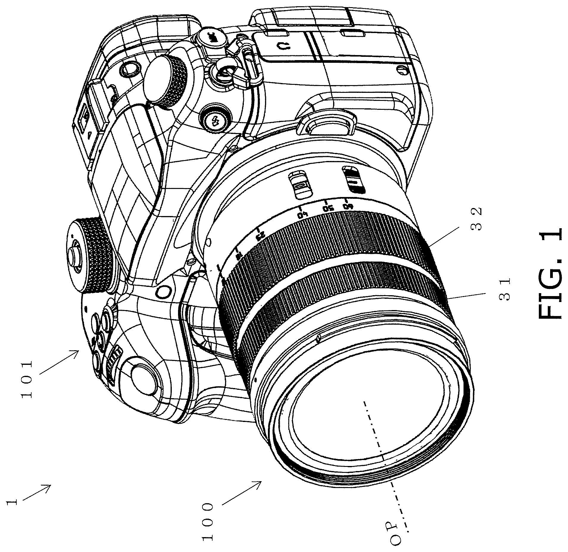
is an overall oblique view showing the configuration of a camera in which the lens barrel according to an embodiment of the present disclosure is mounted on a camera body;
is a cross-sectional view of the lens barrel in ;
A is a cross-sectional view showing a state in which the lens barrel in is in the wide-angle position;
B is a cross-sectional view showing a state in which the lens barrel in is in the telephoto position;
A is a cross-sectional view showing a state in which the cam followers of the third, fourth, and seventh lens group units are engaged with the cam groove of the cam barrel in the wide-angle position in A ;
B is a cross-sectional view showing a state in which the cam followers of the third, fourth, and seventh lens group units are engaged with the cam groove of the cam barrel in the telephoto position in B ;
is an oblique view showing a spacer removably attached to the outer peripheral surface of the rectilinear barrel included in the lens barrel in ;
A is an oblique view showing the positional relationship between the rectilinear barrel in , the cam barrel disposed on the outer peripheral surface side thereof, and the cam followers of the lens group units, in the wide-angle position;
B is an oblique view showing the positional relationship between the rectilinear barrel in , the cam barrel disposed on the outer peripheral surface side thereof, and the cam followers of the lens group units, in the telephoto position;
A is a side view showing the positional relationship between the spacer and the sliding surface in a state in which the rectilinear barrel in and the cam barrel disposed on the outer peripheral surface side thereof are in the wide-angle position;
B is a side view showing the positional relationship between the spacer and the sliding surface in a state in which the rectilinear barrel in and the cam barrel disposed on the outer peripheral surface side thereof are in the telephoto position.
is a detail view of the A portion in A ;
is a front view as seen from the subject side in the optical axis direction, showing a state in which the rectilinear barrel in and the cam barrel disposed on the outer peripheral surface side thereof are supported at three points by a spacer;
A is a detail view of the B 1 portion in ;
B is a detail view of the B 2 portion in ;
C is a detail view of the B 3 portion in ;
is a cross-sectional view showing a state in which a sub-cam follower provided to a cam barrel is engaged in a sub-cam groove provided to the rectilinear barrel with a specific gap therebetween;
A is an oblique view showing a configuration in which the first lens group unit and a base frame are disposed on the outer peripheral surface side of the cam barrel in A ;
B is an oblique view showing a configuration in which a zoom ring is disposed on the outer peripheral surface side of the configuration in A ;
is an oblique view showing the configuration of the zoom ring in B ;
is an oblique view showing a step of attaching a zoom drive pin to the zoom ring in from the outer peripheral surface side thereof;
A is a cross-sectional view showing a configuration in which the zoom drive pin in has moved to the wide-angle position in a state of being fixed to the cam barrel; and
B is a cross-sectional view showing a configuration in which the zoom drive pin in has moved to the telephoto position in a state of being fixed to the cam barrel.
DETAILED DESCRIPTION OF THE PREFERRED EMBODIMENTS
Embodiments of the present disclosure will now be described through reference to the drawings. However, some unnecessarily detailed description may be omitted. For example, detailed description of already known facts or redundant description of components that are substantially the same may be omitted. This is to avoid unnecessary repetition in the following description, and facilitate an understanding on the part of a person skilled in the art.
The applicant has provided the appended drawings and the following description so that a person skilled in the art might fully understand this disclosure, but does not intend for these to limit what is discussed in the patent claims.
Embodiment 1
A lens barrel 100 according to the embodiment of the present disclosure, and a camera 1 equipped with the lens barrel 100 , will now be described with reference to to 15 B .
(1) Configuration of Lens Barrel 100
The configuration of the lens barrel 100 according to an embodiment of the present disclosure will now be described with reference to the drawings. is an oblique view showing the camera 1 in which the lens barrel 100 according to this embodiment is mounted on a camera body 101 .
As shown in , the lens barrel 100 is a retractable lens barrel that is removably attached to the camera body 101 .
As shown in , the lens barrel 100 mainly comprises a rectilinear barrel (fixed barrel) 11 , a cam barrel 12 , a first lens group unit 21 , a second lens group unit 22 , a third lens group unit 23 , a fourth lens group unit 24 , a fifth lens group unit 25 , a sixth lens group unit 26 , a seventh lens group unit 27 , a focus ring 31 , a zoom ring 32 , and a base frame 40 .
The lens barrel 100 also comprises a lens support mechanism 10 that includes the rectilinear barrel 11 and the cam barrel 12 . The detailed configuration of the lens support mechanism 10 will be described in detail below.
The first lens group unit 21 is a substantially cylindrical member disposed on the outer peripheral surface side of the rectilinear barrel 11 , and holds a first lens group L 1 at the end on the subject side in the optical axis OP direction, as shown in . The first lens group unit 21 is disposed closest to the subject in the optical axis OP direction of the lens barrel 100 .
As shown in , the first lens group unit 21 has a substantially cylindrical main body portion 21 a and a cam follower 21 b that is provided on the inner peripheral surface of the substantially cylindrical main body portion 21 a.
The cam follower 21 b of the first lens group unit 21 is provided so as to protrude inward in the radial direction from the outer peripheral surface, near the end portion on the subject side of the inner peripheral surface of the substantially cylindrical main body portion 21 a . The cam follower 21 b is engaged with a rectilinear groove 11 d (see ) formed in the rectilinear barrel 11 and a cam groove 12 d (see A ) formed in the cam barrel 12 , and moves the first lens group unit 21 back and forth in the optical axis OP direction along with the rotation of the cam barrel 12 .
The second lens group unit 22 is a substantially annular member included on the inner peripheral surface side of the rectilinear barrel 11 , and holds a second group lens L 2 as shown in . The second lens group unit 22 is disposed between the first lens group unit 21 and the third lens group unit 23 in the optical axis OP direction of the lens barrel 100 . The second lens group unit 22 is fixed with screws (not shown) to the end surface on the subject side of the rectilinear barrel 11 .
The third lens group unit 23 is a substantially annular member included on the inner peripheral surface side of the rectilinear barrel 11 , and holds the third lens group L 3 as shown in . The third lens group unit 23 is disposed between the second lens group unit 22 and the fourth lens group unit 24 in the optical axis OP direction of the lens barrel 100 .
The third lens group unit 23 has a cam follower 23 a (see A ) provided so as to protrude outward in the radial direction from the outer peripheral surface.
The fourth lens group unit 24 is a substantially cylindrical member included on the inner peripheral surface side of the rectilinear barrel 11 , and holds the fourth lens group L 4 as shown in . The fourth lens group unit 24 is disposed between the third lens group unit 23 and the fifth lens group unit 25 in the optical axis OP direction of the lens barrel 100 .
The fourth lens group unit 24 has a cam follower 24 a (see A ) provided so as to protrude outward in the radial direction from the outer peripheral surface.
The fifth lens group unit 25 is a substantially annular member included on the inner peripheral surface side of the rectilinear barrel 11 , and holds the fifth lens group lens L 5 as shown in . The fifth lens group unit 25 is disposed between the fourth lens group unit 24 and the sixth lens group unit 26 in the optical axis OP direction of the lens barrel 100 . The fifth lens group unit 25 is attached in a state of being suspended from the fourth lens group unit 24 by a guide shaft 28 (see ) that is attached at one end to the fourth lens group unit 24 .
The sixth lens group unit 26 is a substantially annular member included on the inner peripheral surface side of the rectilinear barrel 11 , and holds the sixth lens group L 6 as shown in . The sixth lens group unit 26 is disposed between the fifth lens group unit 25 and the seventh lens group unit 27 in the optical axis OP direction of the lens barrel 100 . Like the fifth lens group unit 25 , the sixth lens group unit 26 is attached in a state of being suspended from the fourth lens group unit 24 by a guide shaft (not shown).
The seventh lens group unit 27 is a substantially annular member included on the inner peripheral surface side of the rectilinear barrel 11 , and holds the seventh lens group L 7 as shown in . The seventh lens group unit 27 is disposed closest to the image plane side (the opposite side from the subject side) in the optical axis OP direction of the lens barrel 100 .
The seventh lens group unit 27 has a cam follower 27 a (see A ) provided so as to protrude outward in the radial direction from the outer peripheral surface.
Here, the first to seventh lens groups L 1 to L 7 held by the first to seventh lens group units 21 to 27 are disposed in that order starting from the subject side, with the optical axis OP as the center axis. With the lens barrel 100 , when the zoom ring 32 (discussed below) is rotated, this moves the first and third to seventh lens group units 21 and 23 to 27 back and forth in the optical axis OP direction between the wide-angle position shown in A and the telephoto position shown in B .
That is, the lens barrel 100 is configured so that upon rotation of the zoom ring 32 attached in a rotatable state to the outer peripheral surface of the base frame 40 , the cam barrel 12 rotates along with the zoom ring 32 . With the lens barrel 100 , when the cam barrel 12 rotates, the first and third to seventh lens group units 21 and 23 to 27 are driven back and forth in the optical axis OP direction.
As shown in A , the first, third, fourth, and seventh lens group units 21 , 23 , 24 , and 27 have a plurality of cam followers ( 21 b , 23 a , 24 a , and 27 a ) that are engaged with a plurality of cam grooves formed in the cam barrel 12 . Also, the cam follower 21 b of the first lens group unit 21 engages with the rectilinear groove 11 d formed in the rectilinear barrel 11 . Also, the cam followers 23 a , 24 a , and 27 a of the third, fourth, and seventh lens group units 23 , 24 , and 27 engage with a rectilinear groove 11 e formed in the rectilinear barrel 11 .
Furthermore, the cam follower 21 b of the first lens group unit 21 engages with the cam groove 12 d formed in the cam barrel 12 . Also, the cam followers 23 a , 24 a , and 27 a of the third, fourth, and seventh lens group units 23 , 24 , and 27 engage with the cam grooves 12 e , 12 f , and 12 g formed in the cam barrel 12 .
Consequently, when the cam barrel 12 is rotated with respect to the rectilinear barrel 11 , the first, third, fourth, and seventh lens group units 21 , 23 , 24 , and 27 are driven back and forth relatively in the optical axis OP direction between the wide-angle position shown in A and the telephoto position shown in B .
(2) Configuration of Lens Support Mechanism 10
The configuration of the lens support mechanism 10 in this embodiment will now be described in detail.
As shown in , etc., the lens support mechanism 10 comprises a rectilinear barrel 11 and a cam barrel 12 .
(2-1) Rectilinear Barrel 11
As shown in , the rectilinear barrel 11 has a substantially cylindrical main body portion 11 a , main cam followers 11 b , a sub-cam groove 11 c , rectilinear grooves 11 d and 11 e , recesses 11 fa and 11 fb , a spacer 11 ga (first spacer, removable spacer) and a spacer 11 gb (second spacer, removable spacer), a spacer 11 ha (first spacer, fixed spacer) and a spacer 11 hb (second spacer, fixed spacer), and a spacer 11 ia (first spacer, fixed spacer) and a spacer 11 ib (second spacer, fixed spacer). shows the positions of the cam followers 23 a , 24 a , and 27 a in the wide-angle position shown in A , etc.
As shown in , the rectilinear groove 11 d that engages with the cam follower 21 b provided to the first lens group unit 21 , and the rectilinear groove 11 e that engages with the cam followers 23 a , 24 a , and 27 a provided to the third, fourth, and seventh lens group units 23 , 24 , and 27 are formed in the substantially cylindrical main body portion 11 a . Three main cam followers 11 b are attached around the circumferential direction near the approximate center of the outer peripheral surface of the main body portion 11 a.
As shown in , the three main cam followers (first cam followers) 11 b are attached so as to protrude from the outer peripheral surface of the substantially cylindrical main body portion 11 a.
For the convenience of illustration, the main cam followers 11 b are directly attached to the outer peripheral surface of the rectilinear barrel 11 in , but in the actual process of assembling the lens barrel 100 , the main cam followers 11 b are attached to the outer peripheral surface of the rectilinear barrel 11 in a state in which the cam barrel 12 has been inserted on the outer peripheral surface side of the rectilinear barrel 11 .
As shown in A and 6 B , the main cam followers 11 b engage with main cam grooves 12 b formed on the cam barrel 12 side, and move along the main cam grooves 12 b as the cam barrel 12 rotates.
As shown in , the sub-cam groove 11 c is a recess formed at an angle to the optical axis OP direction, and engages, via a specific gap, with the sub-cam follower 12 c , which is provided so as to protrude inward in the radial direction from the inner peripheral surface of the main body portion 12 a of the cam barrel 12 . As shown in A and 6 B , the sub-cam groove 11 c is formed so as to be substantially parallel to the main cam grooves 12 b provided on the cam barrel 12 side (discussed below).
Also, an insertion port 11 ca is provided to the sub-cam groove 11 c , on the end on the image plane side.
Consequently, during assembly of the lens barrel 100 , the cam barrel 12 is inserted from the image plane side of the rectilinear barrel 11 while the sub-cam follower 12 c is still attached to the inner peripheral surface side of the main body portion 12 a of the cam barrel 12 , allowing the sub-cam follower 12 c to engage with the sub-cam groove 11 c.
The rectilinear groove 11 d is a through-hole in which the first lens group unit 21 is moved in the optical axis OP direction, and is formed in a straight line along the optical axis OP direction at a position closer to the subject side in the optical axis OP direction as shown in .
The rectilinear groove 11 e is a through-hole in which the third, fourth, and seventh lens group units 23 , 24 , and 27 are moved in the optical axis OP direction, and as shown in , the cam followers 23 a , 24 a , and 27 a of the units 23 , 24 , and 27 are engaged in this groove. The rectilinear groove 11 e is formed in a straightly line along the optical axis OP direction over substantially the entire length of the substantially cylindrical main body portion 11 a in the optical axis OP direction.
As shown in , the recesses 11 fa and 11 fb are recessed portions formed in the outer peripheral surface of the main body portion 11 a of the rectilinear barrel 11 , to which the spacers 11 ga and 11 gb are attached. As shown in , the recesses 11 fa and 11 fb are formed in the outer peripheral surface of the rectilinear barrel 11 along the optical axis OP direction, and are formed near the end on the subject side and near the end on the image plane side in the optical axis OP direction, respectively.
Consequently, the positions where the spacers 11 ga and 11 gb are mounted can be accurately positioned. Also, the depth of the recesses 11 fa and 11 fb ensures room for the thickness of the spacers 11 ga and 11 gb mounted therein, and makes it easier to mold the spacers 11 ga and 11 gb.
Also, the recesses 11 fa and 11 fb are wider in the direction perpendicular to the optical axis OP direction than the spacers 11 ga and 11 gb to be mounted.
Consequently, even if there should be seepage next to the spacers 11 ga and 11 gb when the spacers 11 ga and 11 gb have been mounted with an adhesive agent, these recessed portions can be utilized as an adhesive collector.
As shown in , the spacers 11 ga and 11 gb are attached with an adhesive, for example, in the recesses 11 fa and 11 fb formed on the outer peripheral surface of the main body portion 11 a of the rectilinear barrel 11 . The spacers 11 ga and 11 gb , together with the other spacers 11 ha , 11 hb , 11 ia , and 11 ib , are disposed at intervals of approximately 120 degrees so as to support the inner peripheral surface of the main body portion 12 a of the main body portion 12 a of the cam barrel 12 at three points when viewed from the optical axis OP direction (see ).
Also, as shown in A and 7 B , the spacers 11 ga and 11 gb have a length d 1 that is greater than the length d 2 of the maximum amount of movement (deployment) of the cam barrel 12 with respect to the rectilinear barrel 11 in the optical axis OP direction.
Consequently, when the cam barrel 12 moves from the wide-angle position shown in A to the telephoto position shown in B , the inner peripheral surface of the main body portion 12 a of the cam barrel 12 is prevented from falling off the spacers 11 ga and 11 gb that support at three points.
Furthermore, the spacers 11 ga and 11 gb have a substantially rounded shape in a cross-sectional view in which the upper end surface that slides in contact with the inner peripheral surface of the main body portion 12 a of the cam barrel 12 is perpendicular to the optical axis OP direction.
Also, the substantially rounded shape of the contact surface of the spacers 11 ga and 11 gb is formed so that its curvature is less than the curvature of the sliding surface on the inner peripheral surface side of the main body portion 12 a of the cam barrel 12 .
Consequently, even when the cam barrel 12 moves back and forth in the optical axis OP direction while rotating in the circumferential direction with respect to the outer peripheral surface of the rectilinear barrel 11 , the contact surfaces of the spacers 11 ga and 11 gb , which support the inner peripheral surface of the main body portion 12 a of the cam barrel 12 at three points, can be smoothly rotated and moved without catching.
The gap formed between the outer peripheral surface of the rectilinear barrel 11 and the inner peripheral surface of the main body portion 12 a of the cam barrel 12 , which causes looseness, will vary from one product to the next due to dimensional variance during molding. Therefore, it is preferable to prepare a plurality of spacers 11 ga and 11 gb having different sizes (heights) so that spacers 11 ga and 11 gb having the appropriate size (height) can be selected to match this variance.
The spacers 11 ha , 11 hb , 11 ia , and 11 ib are convex portions formed integrally with the main body portion 11 a of the rectilinear barrel 11 , and are formed so as to protrude outward in the radial direction. The spacers 11 ha and 11 hb are disposed at positions of approximately 120 degrees in the clockwise direction with respect to the spacers 11 ga and 11 gb when viewed from the subject side in the optical axis OP direction (see ). The spacers 11 ia and 11 ib are disposed at positions of approximately 120 degrees in the counterclockwise direction with respect to the spacers 11 ga and 11 gb when viewed from the subject side in the optical axis OP direction (see ).
Also, the spacers 11 ha , 11 hb , 11 ia , and 11 ib are similar to the spacers 11 ga and 11 gb in that they have a length d 1 that is greater than the length d 2 of the maximum amount of movement of the cam barrel 12 with respect to the rectilinear barrel 11 in the optical axis OP direction, as shown in A and 7 B .
Consequently, when the cam barrel 12 moves from the wide-angle position shown in A to the telephoto position shown in B , the inner peripheral surface of the main body portion 12 a of the cam barrel 12 can be prevented from falling off the spacers 11 ha , 11 hb , 11 ia , and 11 ib that support at three points.
Furthermore, the spacers 11 ha , 11 hb , 11 ia , and 11 ib are similar to the spacers 11 ga and 11 gb in that the upper end surface that slides in contact with the inner peripheral surface of the main body portion 12 a of the cam barrel 12 has a substantially rounded shape in a cross-sectional view perpendicular to the optical axis OP direction.
Also, the substantially rounded shape of the contact surface of the spacers 11 ha , 11 hb , 11 ia , and 11 ib is formed so that its curvature is less than the curvature of the sliding surface on the inner peripheral surface side of the main body portion 12 a of the cam barrel 12 .
Consequently, even when the cam barrel 12 moves back and forth in the optical axis OP direction while rotating in the circumferential direction with respect to the outer peripheral surface of the rectilinear barrel 11 , the contact surfaces of the spacers 11 ha , 11 hb , 11 ia , and 11 ib , which support the inner peripheral surface of the main body portion 12 a of the cam barrel 12 at three points, can be smoothly rotated and moved without catching.
(2-2) Cam Barrel 12
As shown in A and 6 B , the cam barrel 12 is disposed on the outer peripheral surface side of the substantially cylindrical rectilinear barrel 11 described above, and has a substantially cylindrical main body portion 12 a , main cam grooves 12 b , a sub-cam follower 12 c , and cam grooves 12 d , 12 e , 12 f , and 12 g.
With the lens barrel 100 in this embodiment, the rectilinear barrel 11 and the cam barrel 12 are inserted on the inner peripheral surface side of the base frame 40 , and the rectilinear barrel 11 is fixed to the base frame 40 with screws (not shown).
Consequently, as shown in A and 6 B , the cam barrel 12 moves back and forth in the optical axis OP direction on the outer peripheral surface side of the rectilinear barrel 11 that is fixed with respect to the base frame 40 .
As shown in A , the substantially cylindrical main body portion 12 a is formed with a plurality of cam grooves including the main cam grooves 12 b and the cam grooves 12 d , 12 e , 12 f , and 12 g.
As shown in A and 6 B , three main cam grooves 12 b are provided near the approximate center of the substantially cylindrical main body portion 12 a so as to correspond to the three main cam followers 11 b provided on the rectilinear barrel 11 side (described above). The three main cam grooves 12 b are provided as substantially linear through-holes formed at an angle to the optical axis OP direction.
The main cam grooves 12 b do not have to be substantially linear, and may be formed along a free curve.
Consequently, when the cam barrel 12 is rotated with respect to the rectilinear barrel 11 , the main cam followers 11 b provided on the rectilinear barrel 11 side move along the main cam grooves 12 b , causing the cam barrel 12 to move back and forth in the optical axis OP direction.
Also, as shown in A , the main cam grooves 12 b are disposed at positions overlapping a part of the sub-cam groove 11 c when viewed from the outer peripheral surface side.
The sub-cam follower 12 c is provided so as to protrude inward in the radial direction from the inner peripheral surface of the main body portion 12 a of the cam barrel 12 . The sub-cam follower 12 c is engaged with the sub-cam groove 11 c provided on the rectilinear barrel 11 side (described above) with a specific gap therebetween.
In this embodiment, the sub-cam follower 12 c is formed separately from the cam barrel 12 , and then attached so as to be embedded in the inner peripheral surface of the main body portion 12 a of the cam barrel 12 , but the sub-cam follower 12 c may instead be molded integrally with the cam barrel 12 .
As shown in A and 6 B , the cam groove 12 d is a through-hole formed in the cam barrel 12 at a position from the end portion on the subject side to near the approximate center, along a direction intersecting the optical axis OP direction, and the cam follower 21 b of the first lens group unit 21 is engaged as shown in . The cam groove 12 d is such that at the wide-angle position shown in A , the cam follower 21 b of the first lens group unit 21 is located at the right end (image plane side), and at the telephoto position shown in B , the cam follower 21 b is located at the left end (subject side).
Consequently, when the cam barrel 12 is rotated with respect to the rectilinear barrel 11 , the cam follower 21 b of the first lens group unit 21 moves along the cam groove 12 d of the cam barrel 12 while engaged with the rectilinear groove 11 d of the rectilinear barrel 11 , which allows the first lens group unit 21 to be moved back and forth in the optical axis OP direction.
As shown in A and 6 B , the cam groove 12 e is a through-hole formed in the cam barrel 12 near the end portion on the subject side, along a direction intersecting the optical axis OP direction, and the cam follower 23 a of the third lens group unit 23 is engaged. The cam groove 12 e is such that at the wide-angle position shown in A , the cam follower 23 a of the third lens group unit 23 is located at the right end (image plane side), and at the telephoto position shown in B , the cam follower 23 a of the third lens group unit 23 is located at the left end (subject side).
Consequently, when the cam barrel 12 is rotated with respect to the rectilinear barrel 11 , the cam follower 23 a of the third lens group unit 23 moves along the cam groove 12 e while engaged with the rectilinear groove 11 e of the rectilinear barrel 11 , which allows the third lens group unit 23 to be moved back and forth in the optical axis OP direction.
As shown in A and 6 B , the cam groove 12 f is a through-hole that is formed in the cam barrel 12 , along a direction intersecting the optical axis OP direction, at a position adjacent to the cam groove 12 e formed near the end portion on the subject side, and the cam follower 24 a of the fourth lens group unit 24 is engaged. The cam groove 12 f is such that at the wide-angle position shown in A , the cam follower 24 a of the fourth lens group unit 24 is located at the right end (image plane side), and at the telephoto position shown in B , the cam follower 24 a of the fourth lens group unit 24 is located at the left end (subject side).
Consequently, when the cam barrel 12 is rotated with respect to the rectilinear barrel 11 , the cam follower 24 a of the fourth lens group unit 24 moves along the cam groove 12 f while engaged with the rectilinear groove 11 e of the rectilinear barrel 11 , which allows the lens group unit 24 to be moved back and forth in the optical axis OP direction.
As shown in A and 6 B , the cam groove 12 g is a through-hole formed in the cam barrel 12 at a position near the end on the image plane side along a direction intersecting the optical axis OP direction, and the cam follower 27 a of the seventh lens group unit 27 is engaged. The cam groove 12 g is such that at the wide-angle position shown in A , the cam follower 27 a of the seventh lens group unit 27 is located at the right end (image plane side), and at the telephoto position shown in B , the cam follower 27 a of the seventh lens group unit 27 is located at the left end (subject side).
Consequently, when the cam barrel 12 is rotated with respect to the rectilinear barrel 11 , the cam follower 27 a of the seventh lens group unit 27 moves along the cam groove 12 g while engaged with the rectilinear groove 11 e of the rectilinear barrel 11 , which allows the lens group unit 27 to be moved back and forth in the optical axis OP direction.
As shown in A and 6 B , a zoom drive pin 33 has already been attached to the outer peripheral surface of the cam barrel 12 . However, in the actual assembly process, the zoom drive pin 33 is fixed to the outer peripheral surface of 12 by being inserted through a pin insertion hole 32 b (discussed below) in a state in which the base frame 40 and the zoom ring 32 have been assembled on the outer peripheral surface side of the cam barrel 12 .
Here, the cam barrel 12 is disposed on the outer peripheral side of the rectilinear barrel 11 , and as shown in A , has sliding surfaces F 1 and F 2 that slide in a state in which spacers 11 ga , 11 gb , 11 ha , 11 hb , 11 ia , and 11 ib are in contact with the inner peripheral surface of the main body portion 12 a . As shown in , the sliding surfaces F 1 and F 2 are smaller than the inside diameter of the portion other than the sliding surfaces F 1 and F 2 .
illustrates the sliding surface F 2 of the spacer 11 gb provided at the end on the image plane side in the optical axis OP direction, but the sliding surface F 1 of the spacer 11 g provided on the subject side is the same. The same applies to the other spacers 11 ha , 11 hb , 11 ia , and 11 ib.
That is, as shown in , the cam barrel 12 has the sliding surface F 2 at the position where the entire upper end surface of the spacer 11 gb does not come into contact with the spacer 11 gb fixed to the recess 11 fb , and only the part on the image plane side comes into contact.
Therefore, as shown in , a gap G 1 is formed by a recess formed on the inner peripheral surface side of the main body portion 12 a of the cam barrel 12 , between the upper end surface of the spacer 11 gb and the inner peripheral surface of the main body portion 12 a of the cam barrel 12 .
Consequently, the sliding surface is limited to a part of the spacer 11 gb , which reduces the rotational torque of the cam barrel 12 with respect to the rectilinear barrel 11 , and allows the cam barrel 12 to be smoothly rotated.
Also, the cam barrel 12 has a sliding surface F 1 (first sliding surface) on the subject side (first end side) in the optical axis OP direction on the inner peripheral surface side thereof, and has a sliding surface F 2 (second sliding surface) on the image plane side (second end side). Within the range in which the cam barrel 12 moves in the optical axis OP direction, the spacer 11 ga is always in contact with the sliding surface F 1 , and the spacer 11 gb is always in contact with the sliding surface F 2 .
Consequently, the spacers 11 ga , 11 gb , 11 ha , 11 hb , 11 ia , and 11 ib are always in contact with the sliding surfaces F 1 and F 2 provided on the inner peripheral surface of the main body portion 12 a of the cam barrel 12 , so the inner peripheral surface of the main body portion 12 a of the cam barrel 12 is supported at three points on the sliding surfaces F 1 and F 2 by the spacers 11 ga , 11 gb , 11 ha , 11 hb , 11 ia , and 11 ib.
Three-Point Support Structure of Cam Barrel with Spacers
With the lens barrel 100 in this embodiment, as shown in , the spacers 11 ga , 11 gb , 11 ha , 11 hb , 11 ia , and 11 ib provided on the outer peripheral surface of the main body portion 11 a of the rectilinear barrel 11 are used to support the inner peripheral surface of the main body portion 12 a of the cam barrel 12 at three points in a state in which rotational movement is possible.
In the view from the subject side in the optical axis OP direction, so only the spacers 11 ga , 11 ha , and 11 ia are shown, but the same applies to the spacers 11 gb , 11 hb , and 11 ib disposed on the image plane side.
That is, as described above, the spacers 11 ga and 11 gb , the spacers 11 ha and 11 hb , and the spacers 11 ia and 11 ib are disposed on the outer peripheral surface of the main body portion 11 a of the rectilinear barrel 11 at intervals of approximately 120 degrees, and support the inner peripheral surface of the main body portion 12 a of the cam barrel 12 at three points.
As described above, the spacer 11 ga is fixed by an adhesive to the recess 11 fa formed in the outer peripheral surface of the main body portion 11 a of the rectilinear barrel 11 as shown in A . The spacer 11 ga protrudes outward in the radial direction from the outer peripheral surface of the main body portion 11 a of the rectilinear barrel 11 , and at the rounded portion of the upper end surface, supports the inner peripheral surface of the main body portion 12 a of the cam barrel 12 , in a state of being in constant contact with the inner peripheral surface of the main body portion 12 a of the cam barrel 12 .
As described above, the spacer 11 ha is molded integrally with the main body portion 11 a of the rectilinear barrel 11 , as shown in B . The spacer 11 ga protrudes outward in the radial direction from the outer peripheral surface of the main body portion 11 a of the rectilinear barrel 11 , and at the rounded portion of the upper end surface thereof, supports the inner peripheral surface of the main body portion 12 a of the cam barrel 12 in a state of being in constant contact with the inner peripheral surface of the main body portion 12 a of the cam barrel 12 .
As described above, the spacer 11 ia is molded integrally with the main body portion 11 a of the rectilinear barrel 11 , as shown in C . The spacer 11 ga protrudes outward in the radial direction from the outer peripheral surface of the main body portion 11 a of the rectilinear barrel 11 , and at the rounded portion of the upper end surface thereof, supports the inner peripheral surface of the main body portion 12 a of the cam barrel 12 in a state of being in constant contact with the inner peripheral surface of the main body portion 12 a of the cam barrel 12 .
Consequently, the three spacers 11 ga , 11 ha , and 11 ia can support the inner peripheral surface of the main body portion 12 a of the cam barrel 12 at three points at their end portion on the subject side in the optical axis OP direction.
Similarly, the three spacers 11 gb , 11 hb , and 11 ib can support the inner peripheral surface of the main body portion 12 a of the cam barrel 12 at three points at their end portion on the image plane side in the optical axis OP direction.
Assembly of Lens Barrel 100
The process of assembling the lens barrel 100 including the lens support mechanism 10 in this embodiment will now be described with reference to A to 15 B .
Specifically, as described above, the rectilinear barrel 11 and the cam barrel 12 are mated in the radial direction of a circle centered on the optical axis OP, with the cam barrel 12 disposed on the outer peripheral surface side of the rectilinear barrel 11 .
First, the main cam followers 11 b of the rectilinear barrel 11 are fixed with screws (not shown) on the outer peripheral surface of the rectilinear barrel 11 , from the outside in the radial direction, as shown in A , in a state in which the cam barrel 12 has been inserted on the outer peripheral surface side of the rectilinear barrel 11 .
Similarly, the cam followers 23 a , 24 a , and 27 a of the third, fourth, and seventh lens group units 23 , 24 , and 27 are fixed with screws (not shown) from the outside in the radial direction, to the main body, etc., of the third, fourth, and seventh lens group units 23 , 24 , and 27 in a state in which the cam barrel 12 has been inserted on the outer peripheral surface side of the rectilinear barrel 11 .
At this point, if the cam barrel 12 is rotated with respect to the rectilinear barrel 11 , rotation of the first, third, fourth, and seventh lens group units 21 , 23 , 24 , and 27 is restricted by the rectilinear grooves 11 d and 11 e , so these units move along the path of the cam grooves 12 d , 12 e , 12 f , 12 g in the optical axis OP direction.
Then, the cam barrel 12 itself also moves in the optical axis OP direction while rotating along the path of the main cam grooves 12 b with which the main cam followers 11 b on the rectilinear barrel 11 side are engaged.
Thus, with this configuration in which the cam barrel 12 is deployed with respect to the rectilinear barrel 11 shown in A and 6 B , the combined amount of movement of the first and the third to seventh lens group units 21 to 27 matches the combined value of the length of the path of cam grooves 12 d , 12 e , 12 f , and 12 g in the optical axis OP direction and the length of the path of the main cam grooves 12 b in the optical axis OP direction.
Next, the rectilinear barrel 11 and the cam barrel 12 are inserted into the base frame 40 as shown in A in a state in which the first to seventh lens group units 21 to 27 have been assembled, and the rectilinear barrel 11 is fixed to the base frame 40 with screws (not shown).
Next, as shown in B , the substantially cylindrical zoom ring 32 is inserted into the outer peripheral surface side of the main body portion 40 a of the substantially cylindrical base frame 40 .
As shown in , the zoom ring 32 has a substantially cylindrical main body portion 32 a , a pin insertion hole 32 b , and a rectilinear restricting groove 32 c.
The pin insertion hole 32 b is a through-hole formed in the main body portion 32 a , and the zoom drive pin 33 is inserted therein in the course of attaching the zoom drive pin 33 to the outer peripheral surface of the cam barrel 12 .
The rectilinear restricting groove 32 c is formed along the optical axis OP direction in order for the head of the zoom drive pin 33 , which is inserted through the pin insertion hole 32 b and is attached to the outer peripheral surface of the cam barrel 12 via a pin escape hole 41 (see A ) of the base frame 40 , to move while engaged.
As shown in , the zoom drive pin 33 is inserted from the outer peripheral surface side through the pin insertion hole 32 b of the zoom ring 32 and the pin escape hole 41 (see A ) of the base frame 40 . The zoom drive pin 33 is fixed with a screw (not shown) to the outer peripheral surface of the cam barrel 12 from the outer peripheral surface side.
At this point, as shown in A and 15 B , the head of the zoom drive pin 33 engages with the rectilinear restricting groove 32 c and is supported so as to be movable in the optical axis OP direction relative to the zoom ring 32 .
Here, when the zoom ring 32 is rotated, the cam barrel 12 is rotationally driven by applying a rotational force in the circumferential direction to the zoom drive pin 33 engaged with the zoom ring 32 .
Then, the cam barrel 12 moves in the optical axis OP direction while rotating as the main cam followers 11 b provided on the rectilinear barrel 11 side move along the main cam grooves 12 b.
At this point, the zoom drive pin 33 slides in the optical axis OP direction while engaged with the rectilinear restricting groove 32 c.
After the zoom drive pin 33 is fixed to the outer peripheral surface of the cam barrel 12 with a screw, a zoom ring rubber 32 d is attached to the outer peripheral surface of the zoom ring 32 as shown in A and 15 B .
Consequently, the pin insertion hole 32 b can be closed up so that the zoom drive pin 33 is not visible from the outside.
Main Features
The lens barrel 100 in this embodiment comprises the first to seventh lens group units 21 to 27 , the substantially cylindrical rectilinear barrel 11 , the substantially cylindrical cam barrel 12 , and the spacers 11 ga , 11 gb , 11 ha , 11 hb , 11 ia , 11 ib . The substantially cylindrical rectilinear barrel 11 holds the third to seventh lens group units 23 to 27 on the inner peripheral surface side, and has the main cam followers 11 b protruding in the radial direction. The substantially cylindrical cam barrel 12 is disposed substantially coaxially with the rectilinear barrel 11 , and has the main cam grooves 12 b that are formed in a direction intersecting the optical axis OP direction in order to move the third to seventh lens group units 23 to 27 in the optical axis OP direction, and that engage with the main cam followers 11 b , and the third to seventh lens group units are rotated relative to the rectilinear barrel 11 in a state in which the main cam followers 11 b and the main cam grooves 12 b are engaged with each other, thereby moving the third to seventh lens group units 23 to 27 in the optical axis OP direction. The spacers 11 ga , 11 gb , 11 ha , 11 hb , 11 ia , and 11 ib protrude in the radial direction from the rectilinear barrel 11 and hit the cam barrel 12 so as to suppress looseness in the radial direction between the rectilinear barrel 11 and the cam barrel 12 , and the length of these spacers in the optical axis OP direction is equal to or greater than the amount of movement of the cam barrel 12 in the optical axis OP direction with respect to the rectilinear barrel 11 .
Here, the spacers 11 ga , 11 gb , 11 ha , 11 hb , 11 ia , and 11 ib have a length d 1 that is equal to or greater than the length d 2 of the maximum amount of movement (deployment amount) of the cam barrel 12 with respect to the rectilinear barrel 11 in the optical axis OP direction, as shown in A and 7 B .
Consequently, when the cam barrel 12 moves from the wide-angle position shown in A to the telephoto position shown in B , the cam barrel 12 can be prevented from falling off the spacers 11 ha , 11 hb , 11 ia , and 11 ib , on which the inner peripheral surface of the main body portion 12 a of the cam barrel 12 is supported at three points, and looseness caused by a gap formed between the rectilinear barrel 11 and the cam barrel 12 can be effectively suppressed without increasing the rotational torque of the cam barrel 12 .
Other Embodiments
An embodiment of the present disclosure was described above, but the present disclosure is not limited to or by the above embodiment, and various modifications are possible without departing from the gist of the disclosure.
(A)
In the above embodiment, an example was given in which two spacers 11 ga and 11 gb divided in the front-rear direction along the optical axis OP direction were attached to the outer peripheral surface of the main body portion 11 a of the rectilinear barrel 11 in a removable state. However, the present disclosure is not limited to this.
For example, the configuration may be such that one spacer is provided in the optical axis direction.
Also, spacers of appropriate sizes do not need to be removably mounted to match individual differences in the gap between the rectilinear barrel (fixed barrel) and the cam barrel, and all of the spacers may be integrally molded on the outer peripheral surface of the rectilinear barrel.
(B)
In the above embodiment, an example was given in which the spacers 11 ga and 11 gb , the spacers 11 ha and 11 hb , and the spacers 11 ia and 11 ib were disposed on the outer peripheral surface of the main body portion 11 a of the rectilinear barrel 11 at intervals of about 120 degrees, respectively, and the inner peripheral surface of the main body portion 12 a of the cam barrel 12 was supported at three points by the spacers 11 ga and 11 gb , etc. However, the present disclosure is not limited to this.
For example, the number of spacers is not limited to six, and may be less than six or more than six.
Also, the number of points at which the cam barrel is supported by the spacers is not limited to three, but three-point support is the basis, and the support points may be further increased.
(C)
In the above embodiment, an example was given in which of the spacers 11 ga and 11 gb , the spacers 11 ha and 11 hb , and the spacers 11 ia and 11 ib that support the inner peripheral surface of the main body portion 12 a of the cam barrel 12 at three points on the outer peripheral surface side of the main body portion 11 a of the rectilinear barrel 11 , the spacers 11 ga and 11 gb were removable, while the other spacers 11 ha , 11 hb , 11 ia and 11 ib were integrally molded (fixed disposition) on the rectilinear barrel 11 . However, the present disclosure is not limited to this.
For example, of the three spacers that provide three-point support, all three of them may be removable, or all three of them may be fixedly disposed.
Alternatively, of the three spacers that provide three-point support, two of them may be removable and one of them may be fixedly disposed.
(D)
In the above embodiment, an example was given in which the spacers 11 ga and 11 gb were disposed near the two ends of the outer peripheral surface of the main body portion 11 a of the rectilinear barrel 11 on the subject side and the image plane side in the optical axis OP direction, respectively. However, the present disclosure is not limited to this.
For example, the positions where the spacers are disposed is not limited to near the two ends on the subject side and the image plane side in the optical axis OP direction of the outer peripheral surface of the main body portion 11 a of the rectilinear barrel 11 , and may be other positions.
(E)
In the above embodiment, an example was given in which the spacers 11 ga and 11 gb were fixed by an adhesive in the recesses 11 fa and 11 fb . However, the present disclosure is not limited to this.
For example, the configuration may be such that the spacers are fixed in the recesses by pressure fitting.
In this case, for example, even if it becomes necessary to replace a spacer because its size does not match the recess in which it is to be fixed, or a spacer is defective, or for some other reason, since the spacer is not fixed with an adhesive, it can be disengaged and easily replaced with the right spacer.
(F)
In the above embodiment, an example was given in which the spacers 11 ga and 11 gb were mounted in the recesses 11 fa and 11 fb formed in the outer peripheral surface of the main body portion 11 a of the rectilinear barrel 11 . However, the present disclosure is not limited to this.
For example, the spacers may be mounted on the outer peripheral surface of a rectilinear barrel in which no recesses have been formed.
(G)
In the above embodiment, an example was given in which the cam barrel 12 disposed on the outer peripheral side of the fixedly disposed rectilinear barrel 11 was driven back and forth in the optical axis OP direction relative to the rectilinear barrel 11 . However, the present disclosure is not limited to this.
For example, the rectilinear barrel may be driven back and forth in the optical axis direction relative to the cam barrel.
(H)
In the above embodiment, an example was given in which the portions of the spacers 11 ga and 11 gb , the spacers 11 ha and 11 hb , and the spacers 11 ia and 11 b that slid over the inner peripheral surface of the main body portion 12 a of the cam barrel 12 had a substantially rounded shape in cross-sectional view, and were smaller than the curvature of the sliding surface on the cam barrel 12 side. However, the present disclosure is not limited to this.
For example, the shape of the sliding portion of the spacers is not limited to a substantially rounded shape, and may be some other shape such as one in which a plurality of spheres are combined.
(I)
In the above embodiment, an example was given in which the present disclosure was applied to a lens barrel 100 that could be attached to and detached from a camera body 101 . However, the present disclosure is not limited to this.
For example, the present disclosure may be applied to a lens barrel that is integrated with a camera body and is not removable, rather than to a removable lens barrel.
INDUSTRIAL APPLICABILITY
The lens barrel disclosed herein has the effect of effectively suppressing looseness caused by a gap formed between a fixed barrel and a cam barrel, without increasing the rotational torque of the cam barrel, and as such is widely applicable to various kinds of lens barrel in which a lens group is driven in the optical axis direction by rotating a cam barrel.
Figures (20)
Citations
This patent cites (14)
- US6115190
- US10018801
- US11366281
- US20030072089
- US20160018621
- US20160202448
- US20200264400
- USS61-171016
- US2004-258638
- US2005-274704
- US2010-008745
- US2015-040971
- US2020-134654
- US2014/136162