Lens Support Mechanism, and Lens Barrel and Camera Provided with the Lens Support Mechanism
Abstract
A lens support mechanism ( 10 ) comprises a fourth lens group unit ( 24 ), a sixth lens group unit ( 26 ), a rectilinear cylinder 11 , a cam cylinder ( 12 ), and a guide shaft ( 29 a ). The rectilinear cylinder 11 is provided on the outer peripheral side of the fourth lens group unit 24 and the sixth lens group unit 26 , and has a rectilinear groove 11 e into which a cam follower 24 b and a main cam follower 26 ba are inserted to restrict the rotation of the fourth lens group unit 24 . A cam groove 12 e and a cam groove 12 h with which the cam follower 24 b and the main cam follower 26 ba are engaged are formed in the cam cylinder 12 , and when the cam cylinder 12 rotates with respect to the rectilinear cylinder 11 , this moves the fourth lens group unit 24 and the sixth lens group unit 26 in the optical axis OP direction. The guide shaft 29 a is fixed at a first end to the fourth lens group unit 24 and inserted into the insertion opening 26 c to guide the sixth lens group unit 26 in the optical axis OP direction.
Claims (12)
1. A lens support mechanism, comprising: a first lens group unit, having a first lens group; a first main body portion that holds the first lens group; and a first cam follower that protrudes outward from an outer peripheral surface of the first main body portion in a radial direction centered on an optical axis of the first lens group; a second lens group unit having a second lens group; a second main body portion that holds the second lens group; one or two second cam followers that protrude outward from an outer peripheral surface of the second main body portion in a radial direction centered on an optical axis of the second lens group; and a first insertion opening that is provided so as to pass through the second main body portion along an optical axis direction; a substantially cylindrical fixed cylinder has a rotation restricting portion that is provided on an outer peripheral side of the first lens group unit and the second lens group unit and into which the first cam follower is inserted to restrict the rotation of the first lens group unit; a substantially cylindrical cam cylinder in which is formed a first cam groove and a second cam groove in which the first cam follower and the second cam follower are engaged, and which rotates with respect to the fixed cylinder to move the first lens group unit and the second lens group unit in the optical axis direction; and a guide shaft that is a rod-shaped member having a first end portion and a second end portion on an opposite side from the first end portion, the first end portion being fixed to the first lens group unit, and that is inserted into the first insertion opening and guides the second lens group unit in the optical axis direction.
Show 11 dependent claims
2. The lens support mechanism according to claim 1 , further comprising: a third lens group unit that has a third lens group, a third main body portion that holds the third lens group, and a second insertion opening that is provided to the third main body portion and into which the guide shaft is inserted, this third lens group unit being provided between the first lens group unit and the second lens group unit; and an actuator configured to apply a driving force for moving the third lens group unit along the guide shaft in the optical axis direction.
3. The lens support mechanism according to claim 2 , wherein in a state in which the first lens group unit and the second lens group unit are closest to each other, the second cam follower is disposed at the same position in the optical axis direction, but offset in the circumferential direction, with respect to the actuator.
4. The lens support mechanism according to claim 2 , wherein in a state in which the first lens group unit and the second lens group unit are closest to each other, the second lens group unit is disposed at the same position in the optical axis direction, but offset in the circumferential direction, with respect to the actuator.
5. The lens support mechanism according to claim 2 , wherein the third lens group is a focus lens.
6. The lens support mechanism according to claim 2 , wherein two or more actuators are provided.
7. The lens support mechanism according to claim 1 , wherein the second lens group unit has, as the second cam follower, a main cam follower that is provided near the first insertion opening into which the guide shaft is inserted, and that is inserted into the second cam groove of the cam cylinder, and a reinforcing cam follower that is protrudes outward in the radial direction from the outer peripheral surface of the second main body portion.
8. The lens support mechanism according to claim 1 , wherein the second lens group unit has a single second cam follower.
9. The lens support mechanism according to claim 1 , wherein the rotation restricting portion is a rectilinear groove that is provided to the fixed cylinder along the optical axis direction.
10. The lens support mechanism according to claim 1 , wherein three first cam followers are provided.
11. A lens barrel, comprising the lens support mechanism according to claim 1 .
12. A camera, comprising: the lens barrel according to claim 11 ; and a camera body to which the lens barrel is mounted.
Full Description
Show full text →
CROSS-REFERENCE TO RELATED APPLICATIONS
This application claims priority to Japanese Patent Application No. 2020-156451 filed on Sep. 17, 2020. The entire disclosure of Japanese Patent Application No. 2020-156451 is hereby incorporated herein by reference.
BACKGROUND OF THE INVENTION
Technical Field
The present disclosure relates to a lens support mechanism included in a lens barrel mounted on a camera body, and to a lens barrel and a camera equipped with this lens support mechanism.
Description of the Related Art
A lens barrel mounted to a camera body comprises a plurality of frame bodies that support an optical system. A first frame body included in the plurality of frame bodies has a cam member, and a second frame body has a guide groove that slides with the cam member inserted therein.
When the first and second frames rotate relative to each other, the cam member is guided by the guide groove, and the two frames move relative to each other in the optical axis direction, thereby realizing a retractable lens barrel.
For example, Patent Literature 1 discloses a lens barrel for a zoom lens optical system having at least four movable lens groups in order to provide a highly accurate and compact zoom lens barrel, wherein the configuration is such that two sliding frames, namely, a sliding frame used for the first to third lens groups and a sliding frame used for the fourth lens group, are fitted inside a fixed cylinder, cam followers are provided to these two sliding frames, the cam cylinder imparts a specific movement to each sliding frame, the second lens group frame is moved within the sliding frame used for the first to third lens groups in conjunction with the drive of the cam cylinder, zooming is performed by imparting movement equal to the difference in the amounts of movement between the sliding frame used for the first to third lens groups and the second lens group frame, and the movement mechanism of the second lens group frame is also used for focusing.
CITATION LIST
Patent Literature
•
• Patent Literature 1: JP-A H3-98007 • Patent Literature 2: JP-A 2010-92031 • Patent Literature 3: JP-A H9-159897
SUMMARY
Problem to be Solved by the Invention
However, conventional configuration described above, zooming and focusing are both performed by the moving mechanism of the second lens group frame, which gives a highly accurate and compact zoom lens barrel, but with a configuration in which a plurality of actuators are provided for driving the focus lens, for example, there is a risk that cam followers and other such parts that move in the optical axis direction will interfere with the actuators and preventing their operation.
It is an object of the present disclosure to provide a lens support mechanism that affords greater latitude in design and allows for a smaller size than in the past, as well as a lens barrel and a camera comprising this lens support mechanism.
Means for Solving Problem
The lens support mechanism according to the present disclosure comprises a first lens group unit, a second lens group unit, a substantially cylindrical fixed cylinder, a substantially cylindrical cam cylinder, and a guide shaft. The first lens group unit has a first lens group, a first main body portion that supports the first lens group, and a first cam follower that protrudes outward from the outer peripheral surface of the first main body portion in the radial direction centered on the optical axis of the first lens group. The second lens group unit has a second lens group, a second main body portion that supports the second lens group, one or two second cam followers that protrude outward from the outer peripheral surface of the second main body portion in the radial direction centered on the optical axis of the second lens group, and a first insertion opening provided so as to pass through the second main body portion along the optical axis direction. The substantially cylindrical fixed cylinder has a rotation restricting portion that is provided on the outer peripheral side of the first lens group unit and the second lens group unit and into which the first cam follower is inserted to restrict the rotation of the first lens group unit. The substantially cylindrical cam cylinder has formed therein a first cam groove and a second cam groove in which the first cam follower and the second cam follower are engaged, and rotates with respect to the fixed cylinder to move the first lens group unit and the second lens group unit in the optical axis direction. The guide shaft is a rod-shaped member having a first end portion and a second end portion on the opposite side from the first end portion, the first end portion being fixed to the first lens group unit, and is inserted into the first insertion opening and guides the second lens group unit in the optical axis direction.
Effects
The lens support mechanism according to the present disclosure affords greater latitude in design and allows for a smaller size than in the past.
BRIEF DESCRIPTION OF DRAWINGS
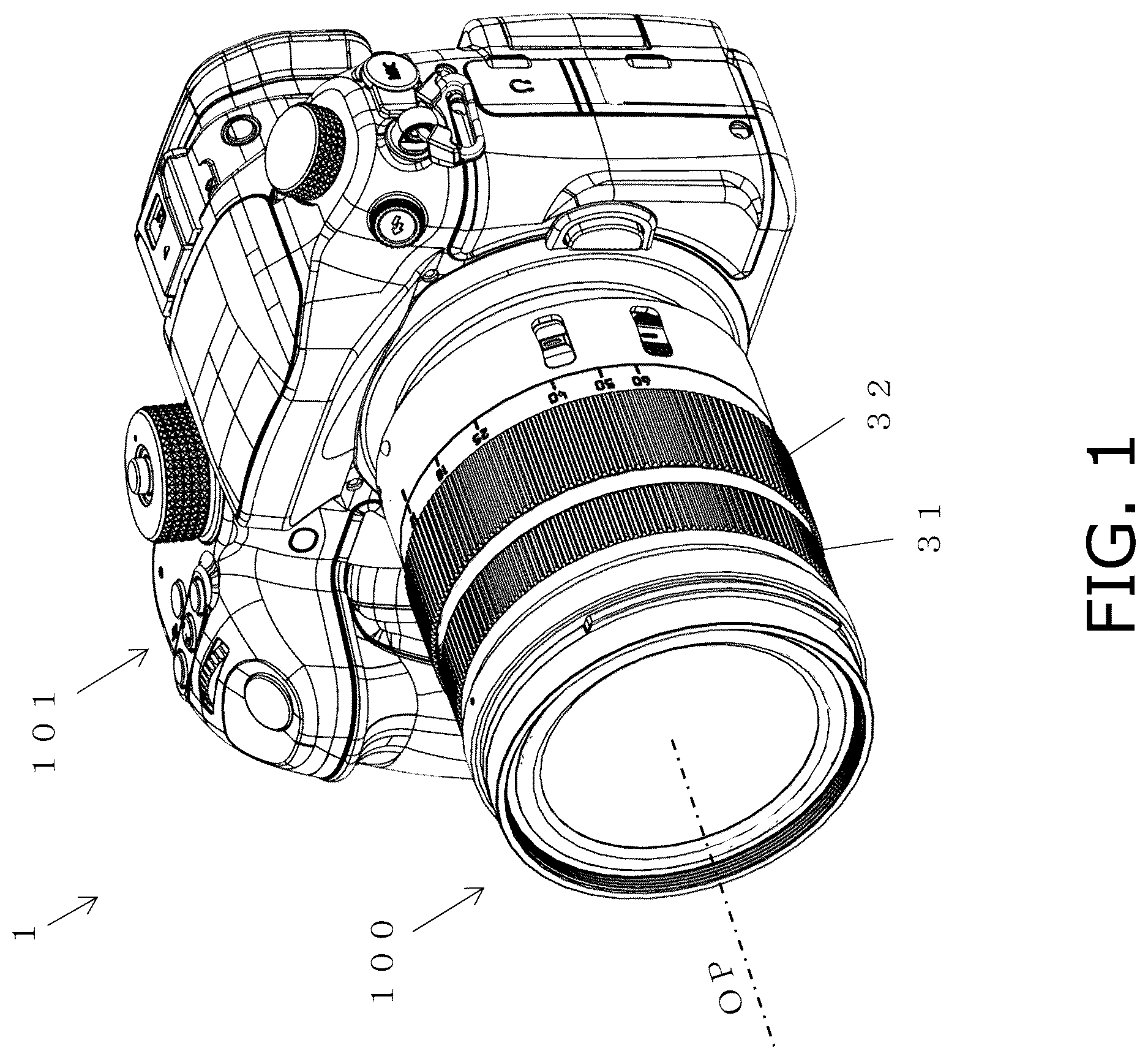
is an oblique view of the configuration of a camera in which a lens barrel including a lens support mechanism according to an embodiment of the present disclosure is attached to a camera body;
is a cross-sectional view of the lens barrel in ;
A is a cross-sectional view of a state in which the lens barrel of is in the wide-angle position;
B is a cross-sectional view showing a state in which the lens barrel of is in the telephoto position;
A is a cross-sectional view showing a state in which the cam followers of the third, fourth, and seventh lens group units at the wide-angle position in A are engaged with a cam groove of a cam cylinder;
B is a cross-sectional view of a state in which the cam followers of the third, fourth, and seventh lens group units at the telephoto position in B are engaged with a cam groove of the cam cylinder;
is a cross-sectional view of a state in which a sub-guide shaft is inserted into an insertion opening of a fifth lens group unit at the wide-angle position in A ;
is a cross-sectional view of a state in which a cam follower of a sixth lens group unit at the wide-angle position in A is engaged with a cam groove of the cam cylinder;
is a cross-sectional view of two actuators that drive the fifth lens group unit and the sixth lens group unit back and forth in the optical axis direction at the wide-angle position in A ;
is an oblique view of a state in which the cam followers of the lens group units disposed on the inner peripheral surface side of the rectilinear cylinder of the lens support mechanism included in the lens barrel in are engaged in a groove of the rectilinear cylinder;
A is an oblique view showing the positional relation between the rectilinear cylinder in , the cam cylinder disposed on the outer peripheral surface side thereof, and the cam followers of the lens group units at the wide-angle position;
B is an oblique view showing the positional relation between the rectilinear cylinder in , the cam cylinder disposed on the outer peripheral surface side thereof, and the cam followers of the lens group units at the telephoto position;
A is an oblique view of a state in which two main guide shafts are inserted into a fourth lens group unit;
B is an oblique view of a state in which two sub-guide shafts are inserted into the fourth lens group unit;
is an oblique view of the configuration of the fourth lens group unit;
A is an oblique view of a state in which two actuators are inserted into the fourth lens group unit;
B is a side view of the configuration of an actuator inserted into the fourth lens group unit;
A is an oblique view of a state in which the fifth lens group unit is inserted on the inner peripheral surface side of the fourth lens group unit;
B is an oblique view of a state in which the sixth lens group unit is inserted on the inner peripheral surface side of the fourth lens group unit;
A is an oblique view of a state in which a side yoke is attached to a main yoke of an actuator inserted on the inner peripheral surface side of the fourth lens group unit;
B is an oblique view of a state in which the side yoke attached in A is fixed with screws;
A is a plan view of a state in which the main yoke and the fifth lens group unit are inserted on the inner peripheral surface side of the fourth lens group unit;
B is a plan view of a state in which the sixth lens group unit is inserted on the inner peripheral surface side of the fourth lens group unit;
C is a plan view of a state in which the side yoke is attached to the inner peripheral surface side of the fourth lens group unit;
A is an oblique view of a state in which a shaft holder is attached to the end portion of the fourth lens group unit on the image plane side;
B is an oblique view of a state in which the shaft holder attached in A is fixed with screws;
A is a side view of a state in which the fourth, fifth, and sixth lens group units are inserted on the inner peripheral surface side of the rectilinear cylinder;
B is a side view of a state in which the fourth, fifth, and sixth lens group units are inserted on the inner peripheral surface side of the rectilinear cylinder;
A is an oblique view of a state in which a cam follower is attached from the outer peripheral surface side of the cam cylinder;
B is an oblique view of a state in which the cam follower attached in A is fixed with a screw;
is a cross-sectional view of a state in which a guide shaft is inserted into an insertion opening of the fifth lens group unit at the wide-angle position in A ;
A is an oblique view of a main cam follower and a reinforcing cam follower of the sixth lens group unit protruding from the outer peripheral surface of the fourth lens group unit; and
B is an oblique view of a main cam follower and a reinforcing cam follower of the sixth lens group unit protruding from the outer peripheral surface of the rectilinear cylinder.
DETAILED DESCRIPTION OF THE EMBODIMENT
Embodiments pertaining to this disclosure will now be described through reference to the drawings. However, some unnecessarily detailed description may be omitted. For example, detailed description of already known facts or redundant description of components that are substantially the same may be omitted. This is to avoid unnecessary repetition in the following description, and facilitate an understanding on the part of a person skilled in the art.
The applicant has provided the appended drawings and the following description so that a person skilled in the art might fully understand this disclosure, but does not intend for these to limit what is discussed in the patent claims.
Embodiment 1
A lens barrel 100 including a lens support mechanism 10 according to an embodiment of the present disclosure will now be described with reference to to 18 B .
(1) Configuration of Lens Barrel 100
The configuration of the lens barrel 100 including the lens support mechanism 10 according to an embodiment of the present disclosure will now be described with reference to the drawings. is an oblique view of a camera 1 in which the lens barrel 100 including the lens support mechanism 10 according to this embodiment is mounted on a camera body 101 .
As shown in , the lens barrel 100 is a retractable lens barrel that is detachably attached to the camera body 101 .
As shown in , the lens barrel 100 mainly comprises a rectilinear cylinder (fixed cylinder) 11 , a cam cylinder 12 , a first lens group unit 21 , a second lens group unit 22 , a third lens group unit 23 , a fourth lens group unit (“first lens group unit” as claimed) 24 , a fifth lens group unit (“third lens group unit” as claimed) 25 , a sixth lens group unit (“second lens group unit” as claimed) 26 , a seventh lens group unit 27 , a focus ring 31 , a zoom ring 32 , and base frame 40 .
The lens barrel 100 also comprises the lens support mechanism 10 , which includes the rectilinear cylinder 11 and the cam cylinder 12 . The detailed configuration of the lens support mechanism 10 will be described in detail below.
The first lens group unit 21 is a substantially cylindrical member disposed on the outer peripheral surface side of the rectilinear cylinder 11 , and holds a first lens group lens L 1 at the end on the subject side in the optical axis OP direction as shown in . The first lens group unit 21 is disposed closest to the subject in the optical axis OP direction of the lens barrel 100 .
As shown in , the first lens group unit 21 has a substantially cylindrical main body portion 21 a and a cam follower 21 b provided to the inner peripheral surface of the substantially cylindrical main body portion 21 a.
The cam follower 21 b of the first lens group unit 21 is provided so as to protrude radially inward from the inner peripheral surface, near the end portion on the image plane side on the inner peripheral surface of the substantially cylindrical main body portion 21 a . The cam follower 21 b is engaged with a rectilinear groove 11 d (see ) formed in the rectilinear cylinder 11 , and a cam groove 12 d (see A ) formed in the cam cylinder 12 , and moves the first lens group unit 21 back and forth in the optical axis OP direction along with the rotation of the cam cylinder 12 .
The second lens group unit 22 is a substantially annular member included on the inner peripheral surface side of the rectilinear cylinder 11 , and holds a second lens group lens L 2 as shown in . The second lens group unit 22 is disposed between the first lens group unit 21 and the third lens group unit 23 in the optical axis OP direction of the lens barrel 100 . The second lens group unit 22 is fixed to the end surface on the subject side of the rectilinear cylinder 11 with screws (not shown).
The third lens group unit 23 is a substantially annular member included on the inner peripheral surface side of the rectilinear cylinder 11 , and holds a third lens group lens L 3 as shown in . The third lens group unit 23 is disposed between the second lens group unit 22 and the fourth lens group unit 24 in the optical axis OP direction of the lens barrel 100 .
The third lens group unit 23 has a cam follower 23 a (see A ) provided so as to protrude radially outward from the outer peripheral surface.
The fourth lens group unit (“first lens group unit” as claimed) 24 is a substantially cylindrical member included on the inner peripheral surface side of the rectilinear cylinder 11 , and holds the fourth lens group lens (“first lens group” as claimed) L 4 as shown in . The fourth lens group unit 24 is disposed between the third lens group unit 23 and the fifth lens group unit 25 in the optical axis OP direction of the lens barrel 100 .
As shown in , the fourth lens group unit 24 has a substantially cylindrical main body portion (“first main body portion” as claimed) 24 a and three cam followers 24 b (“first cam followers” as claimed) provided so as to protrude radially outward from the outer peripheral surface of the main body portion 24 a (see A and 11 ).
The fifth lens group unit (“third lens group unit” as claimed) 25 is a substantially annular member included on the inner peripheral surface side of the rectilinear cylinder 11 , and holds the fifth lens group lens (“third lens group unit” as claimed) L 5 as a focus lens, as shown in . The fifth lens group unit 25 is disposed between the fourth lens group unit 24 and the sixth lens group unit 26 in the optical axis OP direction of the lens barrel 100 . The fifth lens group unit 25 is attached to the fourth lens group unit 24 in suspended state by a guide shaft 28 a (see A and 19 ) that is attached at one end to the fourth lens group unit 24 , and the fifth lens group unit 25 is driven in the optical axis OP direction by actuators 42 and 43 (discussed below; see ).
As shown in A , the fifth lens group unit 25 has a substantially annular main body portion (“third main body portion” as claimed) 25 a , an insertion opening (“second insertion opening” as claimed) 25 b that is formed in the main body portion 25 a and into which the guide shaft 28 a is inserted, a coil 25 c , and an insertion opening 25 d.
The sixth lens group unit (“second lens group unit” as claimed) 26 is a substantially annular member included on the inner peripheral surface side of the rectilinear cylinder 11 , and holds the sixth lens group lens (“second lens group” as claimed) L 6 as shown in . The sixth lens group unit 26 is disposed between the fifth lens group unit 25 and the seventh lens group unit 27 in the optical axis OP direction of the lens barrel 100 . Like the fifth lens group unit 25 , the sixth lens group unit 26 is attached to the fourth lens group unit 24 in a suspended state by a guide shaft 29 a (see ) attached at one end to the fourth lens group unit 24 .
As shown in , the sixth lens group unit 26 has a substantially annular main body portion (“second main body portion” as claimed) 26 a , a main cam follower (“second cam follower” as claimed) 26 ba (see ), a reinforcing cam follower 26 bb , an insertion opening (“first insertion opening” as claimed) 26 c , and a recess 26 d (see B , etc.).
The main cam follower (“second cam follower” as claimed) 26 ba (see ) and the reinforcing cam follower 26 bb (see A and 20 B ) are formed so as to protrude radially outward from the outer peripheral surface of the main body portion 26 a . The main cam follower 26 ba and the reinforcing cam follower 26 bb respectively engage with the cam grooves 12 h and 12 i (see A and 9 B ) formed in the cam cylinder 12 .
The insertion opening (“first insertion opening” as claimed) 26 c is formed in the main body portion 26 a , and the guide shaft 29 a is inserted therein. Consequently, the movement of the sixth lens group unit 26 in the rotation direction around the optical axis OP is restricted by the guide shaft 29 a.
A sub-guide shaft 29 b that restricts the movement of the sixth lens group unit 26 in the rotation direction around the guide shaft 29 a is inserted into the recess 26 d . Consequently, the movement of the sixth lens group unit 26 in the rotation direction around the guide shaft 29 a is restricted by the sub-guide shaft 29 b.
The seventh lens group unit 27 is a substantially annular member included on the inner peripheral surface side of the rectilinear cylinder 11 , and holds the seventh lens group lens L 7 as shown in . The seventh lens group unit 27 is disposed closest to the image plane side, which is on the opposite side from the subject side in the optical axis OP direction of the lens barrel 100 .
The seventh lens group unit 27 has a cam follower 27 a (see A ) provided so as to protrude radially outward from the outer peripheral surface.
Here, the first to seventh lens group lenses L 1 to L 7 held by the first to seventh lens group units 21 to 27 are disposed in that order starting from the subject side, with the optical axis OP as the center axis. In the lens barrel 100 , the rotational operation of the zoom ring 32 (discussed below) moves the first and the third to seventh lens group units 21 and 23 to 27 back and forth along the optical axis OP direction between the wide-angle position shown in A and the telephoto position shown in B .
That is, the lens barrel 100 is configured such that when the zoom ring 32 attached in a rotatable state to the outer peripheral surface of the base frame 40 is rotated, the cam cylinder 12 rotates along with the rotation of the zoom ring 32 . In the lens barrel 100 , when the cam cylinder 12 rotates, the first and the third to seventh lens group units 21 and 23 to 27 are driven back and forth in the optical axis OP direction.
As shown in A , the first, third, fourth, and seventh lens group units 21 , 23 , 24 , and 27 have a plurality of cam followers (cam followers 21 b , 23 a , 24 b , and 27 a ) that respectively engage with a plurality of cam grooves formed in the cam cylinder 12 . Also, the cam follower 21 b of the first lens group unit 21 engages with the rectilinear groove 11 d formed in the rectilinear cylinder 11 . Also, the cam followers 23 a , 24 b , and 27 a of the third, fourth, and seventh lens group units 23 , 24 , and 27 engage with the rectilinear groove 11 e formed in the rectilinear cylinder 11 .
In addition, the cam follower 21 b of the first lens group unit 21 engages with the cam groove 12 d formed in the cam cylinder 12 . Also, the cam followers 23 a , 24 b , and 27 a of the third, fourth, and seventh lens group units 23 , 24 , and 27 engage with the cam grooves 12 e , 12 f , and 12 g formed in the cam cylinder 12 .
Consequently, when the cam cylinder 12 is rotated with respect to the rectilinear cylinder 11 , the first, third, fourth, and seventh lens group units 21 , 23 , 24 , and 27 are driven back and forth in the OP optical axis direction relative to each other, between the wide-angle position shown in A and the telephoto position shown in B .
Also, as shown in , two actuators 42 and 43 are attached on the inner peripheral surface side of the fourth lens group unit 24 included in the lens barrel 100 .
As shown in A and 12 B , the two actuators 42 and 43 are configured to include main yokes 42 a and 43 a , magnets 42 b and 43 b , side yokes 42 c and 43 c , etc., and drive the fifth lens group unit 25 back and forth in the optical axis direction with respect to the fourth lens group unit 24 .
Consequently, an autofocus function can be realized by driving the fifth lens group unit 25 , including the fifth lens group lens L 5 used as the focus lens, back and forth in the optical axis direction.
(2) Configuration of Lens Support Mechanism 10
Next, the configuration of the lens support mechanism 10 in this embodiment will be described in detail.
As shown in and the like, the lens support mechanism 10 comprises the rectilinear cylinder 11 , the cam cylinder 12 , the fourth lens group unit 24 , the sixth lens group unit 26 , and the guide shaft 29 a.
As shown in , the rectilinear cylinder 11 has a substantially cylindrical main body portion 11 a , a main cam follower 11 b , a sub-cam groove 11 c , and rectilinear grooves 11 d and 11 e . shows the positions of the cam followers 23 a , 24 b , and 27 a at the wide-angle position shown in A , etc.
As shown in , the rectilinear groove 11 d with which the cam follower 21 b provided to the first lens group unit 21 is engaged, and the rectilinear groove 11 e with which the cam followers 23 a , 24 b , and 27 a provided to the third, fourth, and seventh lens group units 23 , 24 , and 27 are formed in the substantially cylindrical main body portion 11 a . Three main cam followers 11 b are attached in the circumferential direction near the approximate center of the outer peripheral surface of the main body portion 11 a.
As shown in , the three main cam followers 11 b are attached so as to protrude from the outer peripheral surface of the substantially cylindrical main body portion 11 a.
In , the cam cylinder 12 is shown attached directly to the outer peripheral surface of the rectilinear cylinder 11 to facilitate description, but in the actual assembly process of the lens barrel 100 , the main cam follower 11 b is attached to the outer peripheral surface of the rectilinear cylinder 11 in a state in which the cam cylinder 12 has been inserted on the outer peripheral surface side of the rectilinear cylinder 11 .
As shown in A and 9 B , the main cam followers 11 b engage with main cam grooves 12 b formed on the cam cylinder 12 side and move along the main cam grooves 12 b as the cam cylinder 12 rotates.
As shown in , the sub-cam groove 11 c is a recess (non-through-hole) formed obliquely with respect to the optical axis OP direction, and a sub-cam follower 12 c provided so as to protrude radially inward from the inner peripheral surface of the cam cylinder 12 engages with the sub-cam groove 11 c with a specific gap therebetween. As shown in A and 9 B , the sub-cam groove 11 c is formed so as to be substantially parallel to the main cam grooves 12 b provided on the cam cylinder 12 side (discussed below).
Also, the sub-cam groove 11 c is provided with an insertion opening 11 ca in the end surface on the image plane side.
Consequently, during assembly of the lens barrel 100 , the cam cylinder 12 can be inserted from the end surface on the image plane side of the rectilinear cylinder 11 , and the sub-cam follower 12 c can be engaged with the sub-cam groove 11 c , while the sub-cam follower 12 c is still attached on the inner peripheral surface side of the cam cylinder 12 .
The rectilinear groove 11 d is a through-hole in which the first lens group unit 21 is moved in the optical axis OP direction, and is formed in a straight line along the optical axis OP direction at a position closer to the subject side in the optical axis OP direction, as shown in .
The rectilinear groove 11 e is a through-hole that moves the third, fourth, and seventh lens group units 23 , 24 , and 27 in the optical axis OP direction, and as shown in , the cam followers 23 a , 24 b , and 27 a of the units 23 , 24 , and 27 are engaged with this groove. The rectilinear groove 11 e is formed in a straight line along the optical axis OP direction over substantially the entire length of the substantially cylindrical main body portion 11 a in the optical axis OP direction.
As shown in A and 9 B , the cam cylinder 12 is disposed on the outer peripheral surface side of the substantially cylindrical rectilinear cylinder 11 described above, and has a substantially cylindrical main body portion 12 a , main cam grooves (“first cam grooves” as claimed) 12 b , a sub-cam follower 12 c , and cam grooves 12 d , 12 e , 12 f , 12 g , 12 h , and 12 i (“second cam groove” as claimed).
With the lens barrel 100 in this embodiment, the rectilinear cylinder 11 and the cam cylinder 12 are inserted on the inner peripheral surface side of the base frame 40 , and the rectilinear cylinder 11 is fixed to the base frame 40 with a screw (not shown).
Consequently, as shown in A and 9 B , the cam cylinder 12 moves back and forth in the optical axis OP direction on the outer peripheral surface side of the rectilinear cylinder 11 , which is fixed with respect to the base frame 40 .
As shown in A , a plurality of cam grooves including the main cam grooves 12 b and cam grooves 12 d , 12 e , 12 f , 12 g , 12 h , and 12 i are formed in the substantially cylindrical main body portion 12 a.
As shown in A and 9 B , three main cam grooves 12 b are provided near the approximate center of the substantially cylindrical main body portion 12 a so as to correspond to the three main cam followers 11 b provided on the rectilinear cylinder 11 side as described above. The three main cam grooves 12 b are provided as substantially linear through-holes formed obliquely with respect to the optical axis OP direction.
The main cam grooves 12 b do not have to be substantially linear, and may instead be formed along a free curve.
Consequently, when the cam cylinder 12 is rotated with respect to the rectilinear cylinder 11 , the cam cylinder 12 is moved back and forth in the optical axis OP direction by the main cam followers 11 b provided on the rectilinear cylinder 11 side moving along the main cam grooves 12 b.
Also, as shown in A , the main cam grooves 12 b are disposed at positions overlapping a part of the sub-cam groove 11 c as viewed from the outer peripheral surface side.
Next, the assembly process will be explained for the fourth lens group unit 24 , the fifth lens group unit 25 , and the sixth lens group unit 26 , which are inserted on the inner peripheral surface side of the unit in which the rectilinear cylinder 11 and the cam cylinder 12 shown in A and 9 B are combined.
In the fourth lens group unit 24 , as shown in A , the guide shaft 28 a used for the fifth lens group unit 25 , and the guide shaft 29 a used for the sixth lens group unit 26 are inserted at their respective insertion positions on the inner peripheral surface side of the substantially cylindrical main body portion 24 a holding the fourth lens group lens L 4 . Further, in the fourth lens group unit 24 , as shown in B , the sub-guide shaft 28 b used for the fifth lens group unit 25 , and the sub-guide shaft 29 b used for the sixth lens group unit 26 are inserted at their respective insertion positions on the inner peripheral surface side of the substantially cylindrical main body portion 24 a.
Consequently, two guide shafts 28 a and 29 a and two sub-guide shafts 28 b and 29 b used for the fifth lens group unit 25 and the sixth lens group unit 26 are disposed on the inner peripheral surface side of the main body portion 24 a of the fourth lens group unit 24 .
As shown in , the three cam followers 24 b of the fourth lens group unit 24 are spaced at substantially equal angles (about 120 degrees) so as to protrude radially outward from the outer peripheral surface of the substantially cylindrical main body portion 24 a.
Next, the guide shafts 28 a and 29 a and the sub-guide shafts 28 b and 29 b are disposed on the inner peripheral surface side of the main body portion 24 a of the fourth lens group unit 24 , after which the two actuators 42 and 43 are inserted at positions that are substantially opposite in the radial direction, as shown in A .
The actuators 42 and 43 are configured to include side yokes 42 c and 43 c (discussed below), but here, the main yokes 42 a and 43 a and the magnet 42 b (see B ), excluding the side yokes 42 c and 43 c , are inserted on the inner peripheral surface side of the main body portion 24 a.
As shown in B , the main yokes 42 a and 43 a are substantially E-shaped.
As shown in B , the magnets 42 b and 43 b are attached on the inside of the end portions of the substantially E-shaped main yokes 42 a and 43 a.
Next, as shown in A , the fifth lens group unit 25 , including the fifth lens group lens L 5 as a focus lens, is inserted on the inner peripheral surface side of the main body portion 24 a of the fourth lens group unit 24 . At this point, the guide shaft 28 a is inserted into the insertion opening 25 b of the fifth lens group unit 25 , and the sub-guide shaft 28 b is inserted into the insertion opening 25 d.
At this point, on the inner peripheral surface side of the main body portion 24 a of the fourth lens group unit 24 , as shown in A , the fifth lens group unit 25 is inserted between the two actuators 42 and 43 disposed opposite each other.
Consequently, the fifth lens group unit 25 is attached to the fourth lens group unit 24 in a state of being axially suspended by the guide shaft 28 a or the like whose first end is fixed, and when a current is passed through the coil 25 c , the fifth lens group unit 25 is driven back and forth in the optical axis OP direction by the actuators 42 and 43 .
Next, as shown in B , the sixth lens group unit 26 , including the sixth lens group lens L 6 , is inserted on the inner peripheral surface side of the main body portion 24 a of the fourth lens group unit 24 . At this point, the guide shaft 29 a is inserted into the insertion opening 26 c of the sixth lens group unit 26 , and the sub-guide shaft 29 b is inserted into the recess 26 d.
At this point, on the inner peripheral surface side of the main body portion 24 a of the fourth lens group unit 24 , as shown in B , the sixth lens group unit 26 is inserted between the two actuators 42 and 43 disposed opposite each other. Cam follower fixed portions 26 baa and 26 bba to which the main cam follower 26 ba and the reinforcing cam follower 26 bb of the sixth lens group unit 26 are attached are disposed at positions offset in the circumferential direction (the planar direction in B ) so as not to interfere with the actuators 42 and 43 .
That is, as shown in , etc., in a state in which the fourth lens group unit 24 and the sixth lens group unit 26 are closest, the main cam follower 26 ba and the reinforcing cam follower 26 bb are disposed at the same (overlapping) positions in the optical axis OP direction with respect to the actuators 42 and 43 , and at positions that are offset in the circumferential direction.
Furthermore, in the state where the fourth lens group unit 24 and the sixth lens group unit 26 are closest, the sixth lens group unit 26 is disposed at the same (overlapping) position in the optical axis OP direction with respect to the actuators 42 and 43 , and at a position that is offset in the circumferential direction.
Consequently, the sixth lens group unit 26 is attached in a state of being axially suspended by a guide shaft 29 a or the like whose first end is fixed to the fourth lens group unit 24 . The sixth lens group unit 26 is then driven back and forth in the OP optical axis direction, without interfering with other parts, when the cam cylinder 12 , including the cam groove 12 h with which the main cam follower 26 ba fixed to the cam follower fixing portion 26 ba is engaged, rotates with respect to the rectilinear cylinder 11 .
Next, as shown in A , the side yokes 42 c and 43 c are inserted at the ends of the actuators 42 and 43 that have already been inserted, on the inner peripheral surface side of the main body portion 24 a of the fourth lens group unit 24 .
The side yokes 42 c and 43 c are magnetically integrated with the ends of the main yokes 42 a and 43 a , and are fixed to the fourth lens group unit 24 with screws 44 as shown in B .
At this point, on the inner peripheral surface side of the main body portion 24 a of the fourth lens group unit 24 , as shown in C , the ends of the actuators 42 and 43 are covered by the side yokes 42 c and 43 c.
Next, as shown in A , the shaft holder 45 is attached to the end on the image plane side in a state in which the fifth lens group unit 25 , the sixth lens group unit 26 , and the two actuators 42 and 43 have been inserted on the inner peripheral surface side of the main body portion 24 a of the fourth lens group unit 24 .
As shown in A , the shaft holder 45 is a substantially annular member and has four screw holes 45 a formed in a flat surface portion. The shaft holder 45 holds the guide shaft 28 a and the sub-guide shaft 28 b used for the fifth lens group unit 25 attached on the inner peripheral surface side of the main body portion 24 a of the fourth lens group unit 24 , and the second ends of the guide shaft 29 a and the sub-guide shaft 29 b used for the sixth lens group unit 26 .
Consequently, the guide shaft 28 a and the sub-guide shaft 28 b used for the fifth lens group unit 25 , and the guide shaft 29 a and the sub-guide shaft 29 b used for the sixth lens group unit 26 are held at their first end on the subject side by the fourth lens group unit 24 , and at their second end on the image plane side by the shaft holder 45 .
As shown in B , the shaft holder 45 is fixed to the end surface on the image plane side of the fourth lens group unit 24 by inserting four screws 46 and threading them into screw holes 45 a.
Next, as shown in A , the unit to which the fourth, fifth, and sixth lens group units 24 , 25 , and 26 have been assembled is inserted on the inner peripheral surface side of the rectilinear cylinder 11 in a state in which the rectilinear cylinder 11 has been inserted on the inner peripheral surface side of the cam cylinder 12 .
Then, as shown in B , the unit to which the fourth, fifth, and sixth lens group units 24 , 25 , and 26 have been assembled is attached at a specific position on the inner peripheral surface side of the rectilinear cylinder 11 .
At this point, as shown in A , the cam follower 23 a , the cam follower 24 b , the main cam follower 26 ba , and the reinforcing cam follower 26 bb of the lens group units 23 , 24 , and 26 are fixed with screws 46 to the cam follower fixing portions 26 baa , etc., of the main body portions 24 a and 26 a of the lens group units 23 , 24 , and 26 from the outer peripheral surface side of the cam cylinder 12 .
The cam followers 23 a and 24 b , the main cam follower 26 ba , and the reinforcing cam follower 26 bb fixed by the screws 46 then move in a state of being engaged with the cam groove 12 e and the like formed in the cam cylinder 12 , as shown in B .
A and 18 B show, as an example, a state in which the cam follower 23 a is inserted and attached in the cam groove 12 e , but the cam follower 24 b , the main cam follower 26 ba , and the reinforcing cam follower 26 bb are similarly attached to the outer peripheral surface (cam follower fixing portion 26 baa , etc.) of the main body portion 24 a of the fourth lens group unit 24 and the main body portion 26 a of the sixth lens group unit 26 .
Main Features
The lens support mechanism 10 in this embodiment comprises the fourth lens group unit 24 , the sixth lens group unit 26 , the substantially cylindrical rectilinear cylinder 11 , the substantially cylindrical cam cylinder 12 , and the guide shaft 29 a . The fourth lens group unit 24 has the fourth lens group lens L 4 , the main body 24 a that holds the fourth lens group lens L 4 , and the cam followers 24 b that protrude outward from the outer peripheral surface of the main body 24 a in the radial direction centered on the optical axis OP of the fourth lens group lens L 4 . The sixth lens group unit 26 has the sixth lens group lens L 6 , the main body portion 26 a that holds the sixth lens group lens L 6 , the main cam follower 26 ba that protrudes outward from the outer peripheral surface of the main body portion 26 a in the radial direction centered on the optical axis OP of the sixth lens group lens L 6 , and the insertion opening 26 c provided so as to pass through the main body portion 26 a along the optical axis OP direction. The substantially cylindrical rectilinear cylinder 11 is provided on the outer peripheral side of the fourth lens group unit 24 and the sixth lens group unit 26 , and has the rectilinear groove 11 e (“rotation restricting portion” as claimed) into which the cam followers 24 b are inserted to restrict the rotation of the fourth lens group unit 24 . The cam groove 12 e and the cam groove 12 h with which the cam followers 24 b and the main cam follower 26 ba engage are formed in the substantially cylindrical cam cylinder 12 , and when the cam cylinder 12 rotates with respect to the rectilinear cylinder 11 , the fourth lens group unit 24 and the sixth lens group unit 26 are moved in the optical axis OP direction. The guide shaft 29 a is a rod-shaped member whose first end on the subject side is fixed to the fourth lens group unit 24 and is inserted into the insertion opening 26 c to guide the sixth lens group unit 26 in the optical axis OP direction.
Consequently, in the configuration of the lens barrel 100 in which the fourth lens group unit 24 and the sixth lens group unit 26 move back and forth in the optical axis OP direction when the cam cylinder 12 rotates with respect to the rectilinear cylinder 11 , the sixth lens group unit 26 is axially suspended by the guide shaft 29 a that is fixed at its first end to the fourth lens group unit 24 .
Therefore, in the sixth lens group unit 26 , the main cam follower 26 ba and the reinforcing cam follower 26 bb move along the cam grooves 12 h and 12 i while being supported by the guide shaft 29 a , and thereby move in the optical axis OP direction along with the rotation of the cam cylinder 12 .
As a result, the number of cam followers 26 ba and 26 bb of the sixth lens group unit 26 can be reduced to two or less, which means that there is more latitude in design than with a conventional configuration, and a smaller lens barrel 100 can be obtained.
In particular, with a configuration as in this embodiment, in which two actuators 42 and 43 that drive the fifth lens group unit 25 , including the lens group lens L 5 as the focus lens, back and forth in the optical axis OP direction are provided on the inner peripheral surface side of the fourth lens group unit 24 , space is limited on the inner peripheral surface side of the fourth lens group unit 24 .
Consequently, as in this embodiment, if the sixth lens group unit 26 is axially suspended from a guide shaft that is fixed at its first end to the fourth lens group unit 24 , the number of cam followers 26 ba and 26 bb of the sixth lens group unit 26 can be reduced to two or less.
Therefore, even when the cam cylinder 12 rotates with respect to the rectilinear cylinder 11 and the sixth lens group unit 26 moves back and forth in the optical axis OP direction, the cam follower 26 ba and so forth of the sixth lens group unit 26 can be prevented from interfering with the actuators 42 and 43 and other such parts.
Other Embodiments
An embodiment of the present disclosure was described above, but the present disclosure is not limited to or by the above embodiment, and various modifications are possible without departing from the gist of the disclosure.
(A)
In the above embodiment, an example was given in which the main cam follower 26 ba and the reinforcing cam follower 26 bb of the sixth lens group unit 26 , corresponding to the second cam followers of the second lens group unit, were provided, but the present disclosure is not limited to this.
For example, the configuration may be such that a single main cam follower is provided as the second cam follower, that is, a configuration in which a reinforcing cam follower is not provided.
(B)
In the above embodiment, an example was given in which three cam followers 24 b of the four lens group unit 24 , corresponding to the first cam follower of the first lens group unit, were provided, but the present disclosure is not limited to this.
For example, four or more cam followers of the fourth lens group unit may be provided.
(C)
In the above embodiment, an example was given in which the sixth lens group unit 26 , corresponding to the second lens group unit, and the fifth lens group unit 25 , corresponding to the third lens group unit, moved back and forth in the optical axis OP direction along separate guide shafts 28 a and 29 a . However, the present disclosure is not limited to this.
For example, the second lens group unit and the third lens group unit may be configured to move back and forth in the optical axis direction along a common guide shaft.
(D)
In the above embodiment, an example was given in which the sixth lens group unit 26 , corresponding to the second lens group unit, and the fifth lens group unit 25 , corresponding to the third lens group unit, move back and forth in the OP optical axis direction along the two guide shafts 28 a and 29 a and sub-guide shafts 28 b and 29 b , respectively. However, the present disclosure is not limited to this.
For example, the configuration may be such that there is no sub-guide shaft, and the second lens group unit and the third lens group unit move back and forth in the optical axis direction along just the main guide shaft.
(E)
In the above embodiment, an example was given in which the two actuators 42 and 43 were provided to drive the fifth lens group unit 25 corresponding to the third lens group unit in the optical axis OP direction. However, the present disclosure is not limited to this.
For example, the configuration may be such that just one actuator is provided to drive the third lens group unit in the optical axis direction.
(F)
In the above embodiment, an example was given in which the two actuators 42 and 43 were provided to drive the fifth lens group unit 25 , including the fifth lens group lens L 5 as a focus lens, in the optical axis OP direction. However, the present disclosure is not limited to this.
For example, the configuration may be such that one or three or more actuators provided to drive the lens group unit including the focus lens in the optical axis direction.
(G)
In the above embodiment, an example was given in which the present disclosure was applied to the lens barrel 100 , which could be attached to and detached from the camera body 101 . However, the present disclosure is not limited to this.
For example, the present disclosure may be applied not to a detachable lens barrel, but to a lens barrel that is integrated with the camera body and cannot be removed.
INDUSTRIAL APPLICABILITY
Since the lens support mechanism disclosed herein has the effect of affording greater latitude in design and allowing a reduction in size as compared to a conventional configuration, it can be widely applied to lens barrels and the like that include a lens support mechanism.
Figures (20)
Citations
This patent cites (31)
- US6765728
- US8339503
- US8730376
- US8834044
- US11067769
- US11520117
- US20030184877
- US20100060781
- US20130070150
- US20130148954
- US20190258022
- US20200218030
- US20210181458
- US20220075140
- USH03-098007
- USH0694964
- USH09-159897
- US2000292674
- US2003177297
- US2003295031
- US2008145725
- US2010-092031
- US2010175961
- US2012150368
- US2013210421
- US2013120357
- US2015127729
- US2019144319
- US2019064946
- US2020003921
- US2020137563