Abstract
The present disclosure relates to the technical field of optical lenses, and discloses a camera optical lens. The camera optical lens includes six lenses. An order of the six lenses are sequentially from an object side to an image side, which is shown as follows: a first lens having a negative refractive power, and a second lens having a positive refractive power, a third lens having a positive refractive power, a fourth lens having a negative refractive power, a fifth lens having a positive refractive power, and a sixth lens having a negative refractive power. The camera optical lens provided by the present disclosure has excellent optical characteristics, and further has characteristics of large aperture, wide-angle, and ultra-thin, especially suitable for mobile phone camera lens assemblies and WEB camera lenses, which are composed of camera components having high pixels, such as CCD and CMOS.
Claims (20)
1. A camera optical lens, comprising: six lenses, being sequentially from an object side to an image side, comprising: a first lens having a negative refractive power; a second lens having a positive refractive power; a third lens having a positive refractive power; a fourth lens having a negative refractive power; a fifth lens having a positive refractive power; and a sixth lens having a negative refractive power; wherein, a focal length of the camera optical lens is denoted as f, a focal length of the first lens is denoted as f1, a focal length of the second lens is denoted as f2, a center curvature radius of an object side surface of the second lens is denoted as R3, a center curvature radius of an image side surface of the second lens is denoted as R4, a center curvature radius of an object side surface of the fourth lens is denoted as R7, an on-axis thickness of the fourth lens is denoted as d7, and the camera optical lens satisfies following relationships: 50.00≤ R 7/ d 7; 4.00≤ f 2/ f≤ 5.00; −16.79≤( R 3+ R 4)/( R 3− R 4)≤−2.61; −5.00≤ f 1/ f≤− 2.00.
Show 19 dependent claims
2. The camera optical lens as described in claim 1 , wherein an object side surface of the first lens is concave in a paraxial region, an image side surface of the first lens is convex in a paraxial region; a center curvature radius of the object side surface of the first lens is denoted as R1, a center curvature radius of the image side surface of the first lens is denoted as R2, an on-axis thickness of the first lens is denoted as d1, a total optical length of the camera optical lens is denoted as TTL, and the camera optical lens satisfies following relationships: −5.16≤( R 1+ R 2)/( R 1− R 2)≤−0.47; 0.03≤ d 1/ TTL≤ 0.24.
3. The camera optical lens as described in claim 2 , wherein the camera optical lens satisfies following relationships: −3.22≤( R 1+ R 2)/( R 1− R 2)≤−0.59; 0.05≤ d 1/ TTL≤ 0.20.
4. The camera optical lens as described in claim 1 , wherein the object side surface of the second lens is convex in a paraxial region, the image side surface of the second lens is concave in a paraxial region; an on-axis thickness of the second lens is denoted as d3, and a total optical length of the camera optical lens is denoted as TTL, the camera optical satisfies following relationships: 0.03≤ d 3/ TTL≤ 0.09.
5. The camera optical lens as described in claim 4 , wherein the camera optical lens satisfies following relationships: −10.49≤( R 3+ R 4)/( R 3− R 4)≤−3.26; 0.04≤ d 3/ TTL≤ 0.08.
6. The camera optical lens as described in claim 1 , wherein an object side surface of the third lens is convex in a paraxial region, an image side surface of the third lens is convex in a paraxial region; a focal length of the third lens is denoted as f3, a center curvature radius of the object side surface of the third lens is denoted as R5, a center curvature radius of the image side surface of the third lens is denoted as R6, an on-axis thickness of the third lens is denoted as d5, a total optical length of the camera optical lens is denoted as TTL, and the camera optical satisfies following relationships: 0.64≤ f 3/ f≤ 2.36; 0.03≤( R 5+ R 6)/( R 5− R 6)≤1.51; 0.05≤ d 5/ TTL≤ 0.20.
7. The camera optical lens as described in claim 6 , wherein the camera optical lens satisfies following relationships: 1.02≤ f 3/ f≤ 1.89; 0.05≤( R 5+ R 6)/( R 5− R 6)≤1.20; 0.07≤ d 5/ TTL≤ 0.16.
8. The camera optical lens as described in claim 1 , wherein the object side surface of the fourth lens is convex in a paraxial region, an image side surface of the fourth lens is concave in a paraxial region; a focal length of the fourth lens is denoted as f4, a center curvature radius of the image side surface of the fourth lens is denoted as R8, a total optical length of the camera optical lens is denoted as TTL, and the camera optical satisfies following relationships: −10.43≤ f 4/ f≤− 1.85; 0.50≤( R 7+ R 8)/( R 7− R 8)≤2.78; 0.02≤ d 7/ TTL≤ 0.09.
9. The camera optical lens as described in claim 8 , wherein the camera optical lens satisfies following relationships: −6.52≤ f 4/ f≤− 2.32; 0.80≤( R 7+ R 8)/( R 7− R 8)≤2.23; 0.04≤ d 7/ TTL≤ 0.07.
10. The camera optical lens as described in claim 1 , wherein an object side surface of the fifth lens is concave in a paraxial region, an image side surface of the fifth lens is convex in a paraxial region; a focal length of the fifth lens is denoted as f5, a center curvature radius of the object side surface of the fifth lens is denoted as R9, a center curvature radius of the image side surface of the fifth lens is denoted as R10, an on-axis thickness of the fifth lens is denoted as d9, a total optical length of the camera optical lens is denoted as TTL, the camera optical lens satisfies following relationships: 0.35≤ f 5/ f≤ 1.53; 0.52≤( R 9+ R 10)/( R 9− R 10)≤4.64; 0.07≤ d 9/ TTL≤ 0.39.
11. The camera optical lens as described in claim 10 , wherein the camera optical lens satisfies following relationships: 0.57≤ f 5/ f≤ 1.23; 0.84≤( R 9+ R 10)/( R 9− R 10)≤3.71; 0.11≤ d 9/ TTL≤ 0.31.
12. The camera optical lens as described in claim 1 , wherein an object side surface of the sixth lens is convex in a paraxial region, an image side surface of the sixth lens is concave in a paraxial region; a focal length of the sixth lens is denoted as f6, a center curvature radius of the object side surface of the sixth lens is denoted as R11, a center curvature radius of the image side surface of the sixth lens is denoted as R12, an on-axis thickness of the sixth lens is denoted as d11, a total optical length of the camera optical lens is denoted as TTL, the camera optical lens satisfies following relationships: −2.82≤ f 6/ f≤− 0.63; 1.10≤( R 11+ R 12)/( R 11− R 12)≤4.47; 0.03≤ d 11/ TTL≤ 0.13.
13. The camera optical lens as described in claim 12 , wherein the camera optical lens satisfies following relationships: −1.77≤ f 6/ f≤− 0.78; 1.76≤( R 11+ R 12)/( R 11− R 12)≤3.58; 0.05≤ d 11/ TTL≤ 0.11.
14. The camera optical lens as described in claim 1 , wherein an image height of the camera optical lens is denoted as IH, a total optical length of the camera optical lens is denoted as TTL, the camera optical lens satisfies a following relationship: TTL/IH≤ 1.89.
15. The camera optical lens as described in claim 14 , wherein the camera optical lens satisfies a following relationship: TTL/IH≤ 1.84.
16. The camera optical lens as described in claim 1 , wherein a field of view of the camera optical lens is denoted as FOV, the FOV is greater than or equal to 112.83°.
17. The camera optical lens as described in claim 16 , wherein the FOV is greater than or equal to 113.98°.
18. The camera optical lens as described in claim 1 , wherein an F number of the camera optical lens is denoted as FNO, the FNO is less than or equal to 2.40.
19. The camera optical lens as described in claim 18 , wherein the FNO is less than or equal to 2.35.
20. The camera optical lens as described in claim 18 , wherein a combined focal length of the first lens and the second lens is denoted as f12, and satisfies a following relationship: −58.06≤ f 12/ f≤ 18.34.
Full Description
Show full text →
TECHNICAL FIELD
The present disclosure relates to the field of optical lens, and in particular to a camera optical lens suitable for handheld devices, such as smart phones, digital cameras, and imaging devices, such as monitors or PC lenses.
BACKGROUND
With emergence of smart phones in recent years, demand for miniature camera lens is increasing day by day, and because a pixel size of per photosensitive device shrinks, in addition a development trend of electronic products with good functions, and thin and portable appears, therefore, a miniaturized camera optical lens having good imaging quality becomes a mainstream in current market. In order to obtain better imaging quality, multi-piece lens structure is mainly adopted. Moreover, with development of technology and increases of diversified needs of users, a pixel area of per photosensitive device is constantly shrinking, and requirements of optical systems for imaging quality are constantly increase. A six-piece lens structure gradually appears in lens design. There is an urgent need for a wide-angled camera lens having excellent optical ch
SUMMARY
Aiming at the above problems, the present disclosure seeks to provide a camera optical lens, which has good optical performance and meets design requirements of large aperture, ultra-thinness, and wide-angle.
In order to solve the above problems, embodiments of the present disclosure provide a camera optical lens. The camera optical lens includes six lenses. An order of the six lenses is sequentially from an object side to an image side, which is shown as follows: a first lens having a negative refractive power, and a second lens having a positive refractive power, a third lens having a positive refractive power, a fourth lens having a negative refractive power, a fifth lens having a positive refractive power, and a sixth lens having a negative refractive power. A focal length of the camera optical lens is f, a focal length of the first lens is f1, a focal length of the second lens is f2, a center curvature radius of an object side surface of the second lens is R3, a center curvature radius of an image side surface of the second lens is R4, a center curvature radius of an object side surface of the fourth lens is R7, an on-axis thickness of the fourth lens is d7, and the camera optical lens satisfies following relationship: 50.00≤ R 7/ d 7; 4.00≤ f 2/ f≤ 5.00; −16.79≤( R 3+ R 4)/( R 3− R 4)≤−2.61; −5.00≤ f 1/ f≤− 2.00.
As an improvement, an object side surface of the first lens is concave in a paraxial region, an image side surface of the first lens is convex in a paraxial region. A center curvature radius of the object side surface of the first lens is R1, a center curvature radius of the image side surface of the first lens is R2, an on-axis thickness of the first lens is d1, a total optical length of the camera optical lens is TTL, and the camera optical lens satisfies following relationships: 5.16≤( R 1+ R 2)/( R 1− R 2)≤−0.47; 0.03≤ d 1/ TTL≤ 0.24.
As an improvement, the camera optical lens satisfies following relationships: −3.22≤( R 1+ R 2)/( R 1− R 2)≤−0.59; 0.05≤ d 1/ TTL≤ 0.20.
As an improvement, the object side surface of the second lens is concave in a paraxial region, the image side surface of the second lens is convex in a paraxial region, an on-axis thickness of the second lens is d3, and a total optical length of the camera optical lens is TTL, the camera optical lens satisfies following relationships: 0.03≤ d 3/ TTL≤ 0.09.
As an improvement, the camera optical lens satisfies following relationships: 10.49≤( R 3+ R 4)/( R 3− R 4)≤−3.26; 0.04≤ d 3/ TTL≤ 0.08.
As an improvement, an object side surface of the third lens is concave in a paraxial region, an image side surface of the third lens is convex in a paraxial region, a focal length of the third lens is f3, a center curvature radius of the object side surface of the third lens is R5, a center curvature radius of the image side surface of the third lens is R6, an on-axis thickness of the third lens is d5, a total optical length of the camera optical lens is TTL, the camera optical lens satisfies following relationships: 0.64≤ f 3/ f≤ 2.36; 0.03≤( R 5+ R 6)/( R 5− R 6)≤1.51; 0.05≤ d 5/ TTL≤ 0.20.
As an improvement, the camera optical lens satisfies following relationships: 1.02≤ f 3/ f≤ 1.89; 0.05≤( R 5+ R 6)/( R 5− R 6)≤1.20; 0.07≤ d 5/ TTL≤ 0.16.
As an improvement, the object side surface of the fourth lens is concave in a paraxial region, an image side surface of the fourth lens is convex in a paraxial region, a focal length of the fourth lens is f4, a center curvature radius of the image side surface of the fourth lens is R8, a total optical length of the camera optical lens is TTL, the camera optical lens satisfies following relationships: −10.43≤ f 4/ f≤− 1.85; 0.50≤( R 7+ R 8)/( R 7− R 8)≤2.78; 0.02≤ d 7/ TTL≤ 0.09.
As an improvement, the camera optical lens satisfies following relationships: −6.52≤ f 4/ f≤− 2.32; 0.80≤( R 7+ R 8)/( R 7− R 8)≤2.23; 0.04≤ d 7/ TTL≤ 0.07.
As an improvement, an object side surface of the fifth lens is concave in a paraxial region, an image side surface of the fifth lens is convex in a paraxial region, a focal length of the fifth lens is f5, a center curvature radius of the object side surface of the fifth lens is R9, a center curvature radius of the image side surface of the fifth lens is R10, an on-axis thickness of the fifth lens is d9, a total optical length of the camera optical lens is TTL, the camera optical lens satisfies following relationships: 0.35≤ f 5/ f≤ 1.53; 0.52≤( R 9+ R 10)/( R 9− R 10)≤4.64; 0.07≤ d 9/ TTL≤ 0.39.
As an improvement, the camera optical lens satisfies following relationships: 0.57≤ f 5/ f≤ 1.23; 0.84≤( R 9+ R 10)/( R 9− R 10)≤3.71; 0.11≤ d 9/ TTL≤ 0.31.
As an improvement, an object side surface of the sixth lens is concave in a paraxial region, an image side surface of the sixth lens is convex in a paraxial region, a focal length of the sixth lens is f6, a center curvature radius of the object side surface of the sixth lens is R11, a center curvature radius of the image side surface of the sixth lens is R12, an on-axis thickness of the sixth lens is d11, a total optical length of the camera optical lens is TTL, the camera optical lens satisfies following relationships: −2.82≤ f 6/ f≤− 0.63; 1.10≤( R 11+ R 12)/( R 11− R 12)≤4.47; 0.03≤ d 11/ TTL≤ 0.13.
As an improvement, the camera optical lens satisfies following relationships: −1.77≤ f 6/ f≤− 0.78; 1.76≤( R 11+ R 12)/( R 11− R 12)≤3.58; 0.05≤ d 11/ TTL≤ 0.11.
As an improvement, an image height of the camera optical lens is IH, a total optical length of the camera optical lens is TTL, the camera optical lens satisfies a following relationship: TTL/IH≤ 1.89.
As an improvement, the camera optical lens satisfies a following relationship: TTL/IH≤ 1.84.
As an improvement, a field of view of the camera optical lens is FOV, the FOV is greater than or equal to 112.83°.
As an improvement, the FOV is greater than or equal to 113.98°.
As an improvement, an F number of the camera optical lens is FNO, the FNO is less than or equal to 2.40.
As an improvement, the FNO is less than or equal to 2.35.
As an improvement, a combined focal length of the first lens and the second lens is f12, and satisfies a following relationship: −58.06≤ f 12/ f≤ 18.34.
The beneficial effects of the present disclosure are as follows. The camera optical lens provided by the present disclosure has excellent optical characteristics, and further has characteristics of large aperture, wide-angle, and ultra-thin, especially suitable for mobile phone camera lens assemblies and WEB camera lenses, which are composed of camera components having high pixels, such as CCD and CMOS.
BRIEF DESCRIPTION OF DRAWINGS
To more clearly illustrate the technical solutions in the embodiments of the present disclosure clearer, accompanying drawings that need to be used in the description of the embodiments will briefly introduce in the following. Obviously, the drawings described below are only some embodiments of the present disclosure. For a person of ordinary skill in the art, other drawings can be obtained according to these without creative labor, wherein:
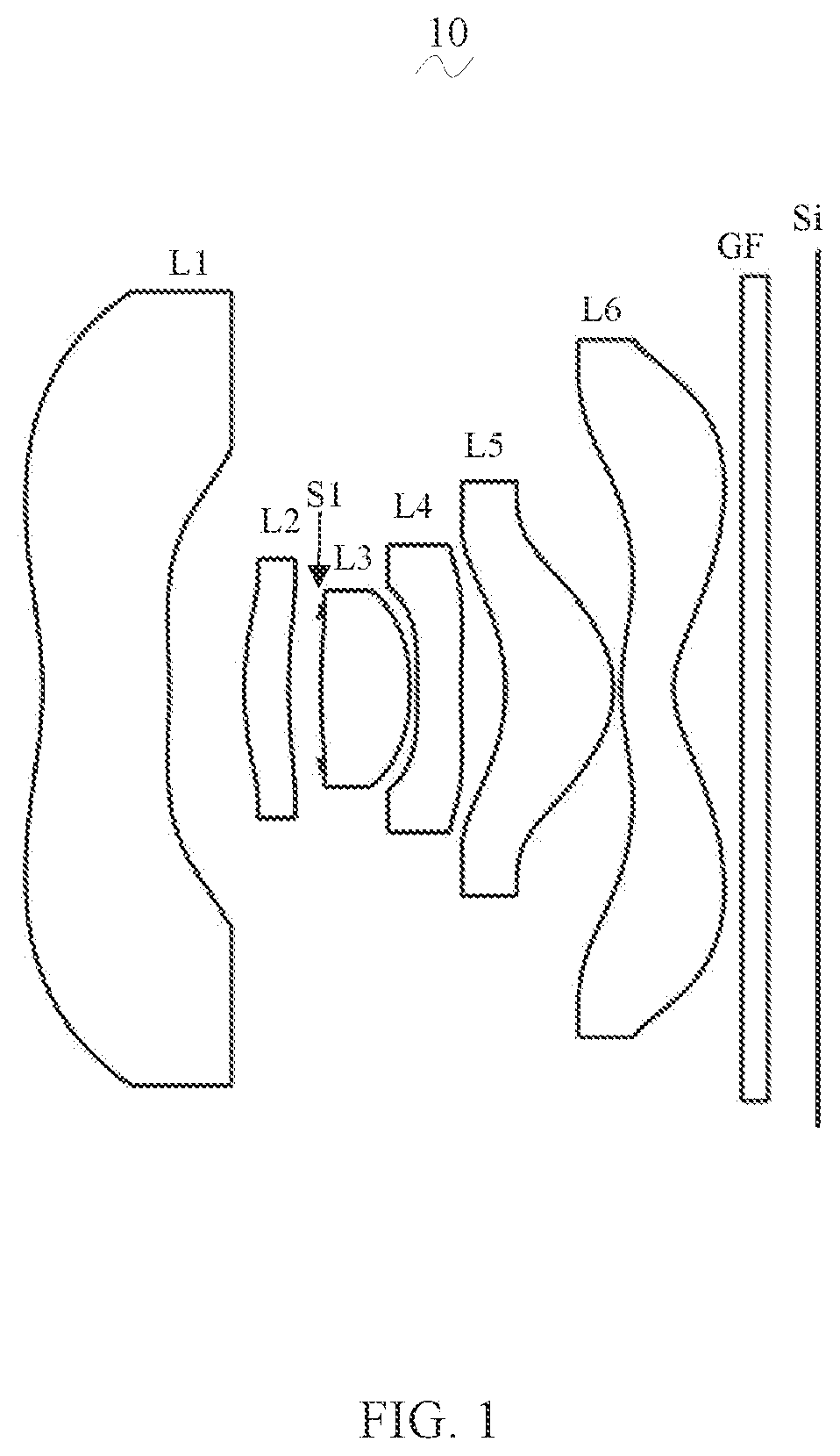
is a schematic diagram of a structure of a camera optical lens according to a first embodiment of the present disclosure.
is a schematic diagram of a longitudinal aberration of the camera optical lens shown in .
is a schematic diagram of a lateral color of the camera optical lens shown in .
is a schematic diagram of a field curvature and a distortion of the camera optical lens shown in .
is a schematic diagram of a structure of a camera optical lens according to a second embodiment of the present disclosure.
is a schematic diagram of a longitudinal aberration of the camera optical lens shown in .
is a schematic diagram of a lateral color of the camera optical lens shown in .
is a schematic diagram of a field curvature and a distortion of the camera optical lens shown in .
is a schematic diagram of a structure of a camera optical lens according to a third embodiment of the present disclosure.
is a schematic diagram of a longitudinal aberration of the camera optical lens shown in .
is a schematic diagram of a lateral color of the camera optical lens shown in .
is a schematic diagram of a field curvature and a distortion of the camera optical lens shown in .
DETAILED DESCRIPTION OF EMBODIMENTS
In order to make the objects, technical solutions, and advantages of the present disclosure clearer, embodiments of the present disclosure are described in detail with reference to accompanying drawings in the following. A person of ordinary skill in the art can understand that, in the embodiments of the present disclosure, many technical details are provided to make readers better understand the present disclosure. However, even without these technical details and any changes and modifications based on the following embodiments, technical solutions required to be protected by the present disclosure can be implemented.
Embodiment 1
Referring to the drawings, the present disclosure provides a camera optical lens 10 . shows the camera optical lens 10 of a first embodiment of the present disclosure. The camera optical lens 10 includes six lenses. Specifically, an order of the camera optical lens 10 is sequentially from an object side to an image side, which is shown as follows: a first lens L 1 , a second lens L 2 , a third lens L 3 , a fourth lens L 4 , a fifth lens L 5 , and a sixth lens L 6 . An optical element such as an optical filter GF may be arranged between the sixth lens L 6 and an image surface Si.
In the embodiment, the first lens L 1 is made of a plastic material, the second lens L 2 is made of a plastic material, the third lens L 3 is made of a plastic material, the fourth lens L 4 is made of a plastic material, the fifth lens L 5 is made of a plastic material, and the sixth lens L 6 is made of a plastic material. In other alternative embodiments, the lenses may be made of other materials.
In the embodiment, a center curvature radius of an object side surface of the fourth lens L 4 is denoted as R7, an on-axis thickness of the fourth lens L 4 is denoted as d7, the camera optical lens satisfies a following relationship: 50.00≤R7/d7. The focal power of the fourth lens L 4 is controlled in a reasonable range, which is beneficial to correct aberrations of an optical system.
A focal length of the camera optical lens 10 is denoted as f, a focal length of the second lens L 2 is denoted as f2, and the camera optical lens satisfies a following relationship: 4.00≤f2/f≤5.00. The positive focal power of the second lens L 2 is controlled in a reasonable range, which is beneficial to correct the aberrations of the optical system.
A focal length of the first lens L 1 is denoted as f1, which satisfies a following relationship: −5.00≤f1/f≤−2.00 and specifies a negative refractive power of the first lens L 1 . When an upper limit value is exceeded, although it is beneficial to ultra-thin development of the camera optical lens 10 , the negative refractive power of the first lens L 1 may be too strong, and it is difficult to correct problems such as aberrations, and it is not beneficial to wide-angled development of the camera optical lens 10 . Conversely, when a lower limit is exceeded, the negative refractive power of the first lens L 1 may be too weak, and it is difficult for ultra-thin development of the camera optical lens 10 .
In the embodiment, an object side surface of the first lens L 1 is concave in a paraxial region, an image side surface of the first lens L 1 is convex in a paraxial region, and the first lens L 1 has a negative refractive power. In other alternative embodiments, both the object side surface and the image side surface of the first lens L 1 may be replaced with other concave and convex distributions.
A center curvature radius of the object side surface of the first lens L 1 is denoted as R1, a center curvature radius of the image side surface of the first lens L 1 is R2, the camera optical lens satisfies a following relationship: −5.16≤(R1+R2)/(R1−R2)≤−0.47. A shape of the first lens L 1 is reasonably controlled, so that the first lens L 1 may effectively correct spherical aberration of the optical system. As an improvement, a following relationship is satisfied: −3.22≤(R1+R2)/(R1−R2)≤−0.59.
An on-axis thickness of the first lens L 1 is denoted as d1, a total optical length of the camera optical lens 10 is denoted as TTL, and the camera optical lens satisfies a following relationship: 0.03≤d1/TTL≤0.24. In a range of the conditional formula, it is beneficial to achieve ultra-thinness. As an improvement, a following relationship is satisfied: 0.05≤d1/TTL≤0.20.
In the embodiment, an object side surface of the second lens L 2 is convex in a paraxial region, an image side surface of the second lens L 2 is concave in a paraxial region. The second lens L 2 has a positive refractive power. In other alternative embodiments, both the object side surface and the image side surface of the second lens L 2 may be replaced with other concave and convex distributions.
A center curvature radius of the object side surface of the second lens L 2 is denoted as R3, a center curvature radius of the image side surface of the second lens L 2 is R4, the camera optical lens satisfies a following relationship: −16.79≤(R3+R4)/(R3−R4)≤−2.61 and further specifies a shape of the second lens L 2 . In a range of the conditional formula, with development of the camera optical lenses toward to ultra-thinness and wide-angle, it is beneficial to correct a problem of axial chromatic aberration. As an improvement, a following relationship is satisfied: −10.49≤(R3+R4)/(R3−R4)≤−3.26.
An on-axis thickness of the second lens L 2 is denoted as d3, a total optical length of the camera optical lens 10 is denoted as TTL, which satisfies a following relationship: 0.03≤d3/TTL≤0.09. In a range of the conditional formula, it is beneficial to achieve ultra-thinness. As an improvement, a following relationship is satisfied: 0.04≤d3/TTL≤0.08.
In the embodiment, an object side surface of the third lens L 3 is convex in a paraxial region, an image side surface of the third lens L 3 is concave in a paraxial region. The third lens L 3 has a positive refractive power. In other alternative embodiments, both the object side surface and the image side surface of the third lens L 3 may be replaced with other concave and convex distributions.
A focal length of the camera optical lens 10 is denoted as f, a focal length of the third lens L 3 is denoted as f3, which satisfies a following relationship: 0.64≤f3/f≤2.36. Through a reasonable distribution of the focal power, the optical system has better imaging quality and lower sensitivity. As an improvement, a following relationship is satisfied: 1.02≤f3/f≤1.89.
A center curvature radius of the object side surface of the third lens L 3 is denoted as R5, a center curvature radius of the image side surface of the third lens L 3 is R6, which satisfies a following relationship: 0.03≤(R5+R6)/(R5−R6)≤1.51, and further specifies a shape of the third lens L 3 and being beneficial to molding of the third lens L 3 . In a range of the conditional formula, it may alleviate deflection degree of light passing through the lenses and effectively reduce aberration. As an improvement, a following relationship is satisfied: 0.05≤(R5+R6)/(R5−R6)≤1.20.
An on-axis thickness of the third lens L 3 is denoted as d5, a total optical length of the camera optical lens 10 is denoted as TTL, which satisfies the following relationship: 0.05≤d5/TTL≤0.20. In a range of the conditional formula, it is beneficial to achieve ultra-thinness. As an improvement, a following relationship is satisfied: 0.07≤d5/TTL≤0.16.
In the embodiment, an object side surface of the fourth lens L 4 is convex in a paraxial region, an image side surface of the fourth lens L 4 is concave in a paraxial region. The fourth lens L 4 has a negative refractive power. In other alternative embodiments, both the object side surface and the image side surface of the fourth lens L 4 may be replaced with other concave and convex distributions.
A focal length of the camera optical lens 10 is denoted as f, a focal length of the fourth lens L 4 is denoted as f4, which satisfies a following relationship: −10.43≤f4/f≤−1.85. Through a reasonable distribution of the focal power, the optical system has better imaging quality and lower sensitivity. As an improvement, a following relationship is satisfied: −6.52≤f4/f≤−2.32.
A center curvature radius of the object side surface of the fourth lens L 4 is denoted as R7, a center curvature radius of the image side surface of the fourth lens L 4 is denoted as R8, the camera optical lens satisfies a following relationship: 0.50≤(R7+R8)/(R7−R8)≤2.78, which specifies a shape of the fourth lens L 4 . Within a range of the conditional formula, with the ultra-thin and wide-angle development, it is beneficial to correct aberrations of off-axis angle of view and other problems. As an improvement, a following relationship is satisfied: 0.80≤(R7+R8)/(R7−R8)≤2.23.
An on-axis thickness of the fourth lens L 4 is denoted as d7, a total optical length of the camera optical lens 10 is denoted as TTL, which satisfies a following relationship: 0.02≤d7/TTL≤0.09. In a range of the conditional formula, it is beneficial to achieve ultra-thinness. As an improvement, a following relationship is satisfied: 0.04≤d7/TTL≤0.07.
In the embodiment, an object side surface of the fifth lens L 5 is concave in a paraxial region, an image side surface of the fifth lens L 5 is convex in a paraxial region. The fifth lens L 5 has a positive refractive power.
A focal length of the camera optical lens 10 is denoted as f, a focal length of the fifth lens L 5 is denoted as f5, which satisfies a following relationship: 0.35≤f5/f≤1.53. A limitation of the fifth lens L 5 may effectively make a light angle of the camera optical lens 10 smooth and reduce tolerance sensitivity. As an improvement, a following relationship is satisfied: 0.57≤f5/f≤1.23.
A center curvature radius of the object side surface of the fifth lens L 5 is denoted as R9, a center curvature radius of the image side surface of the fifth lens L 5 is denoted as R10, which satisfies a following relationship: 0.52≤(R9+R10)/(R9−R10)≤4.64, and further specifies a shape of the fifth lens L 5 . In a range of the conditional formula, with the ultra-thin and wide-angle development, it is beneficial to correct the aberrations of off-axis angle of view and other problems. As an improvement, a following relationship is satisfied: 0.84≤(R9+R10)/(R9−R10)≤3.71.
An on-axis thickness of the fifth lens L 5 is denoted as d9, a total optical length of the camera optical lens 10 is denoted as TTL, which satisfies a following relationship: 0.07≤d9/TTL≤0.39. In a range of the conditional formula, it is beneficial to achieve ultra-thinness. As an improvement, a following relationship is satisfied: 0.11≤d9/TTL≤0.31.
In the embodiment, an object side surface of the sixth lens L 6 is convex in a paraxial region, an image side surface of the sixth lens L 6 is concave in a paraxial region. The sixth lens L 6 has a negative refractive power. In other alternative embodiments, both the object side surface and the image side surface of the sixth lens L 6 may be replaced with other concave and convex distributions.
A focal length of the camera optical lens 10 is denoted as f, a focal length of the sixth lens L 6 is denoted as f6, which satisfies following relationships: −2.82≤f6/f≤−0.63. Through a reasonable distribution of the focal power, the optical system has better imaging quality and lower sensitivity. As an improvement, a following relationship is satisfied: −1.77≤f6/f≤−0.78.
A center curvature radius of the object side surface of the sixth lens L 6 is denoted as R11, a center curvature radius of the image side surface of the sixth lens L 6 is denoted as R12, which satisfies following relationships: 1.10≤(R11+R12)/(R11−R12)≤4.47, and further specifies a shape of the sixth lens L 6 . In a range of the conditional formula, with the ultra-thin and the wide-angle development, it is beneficial to correct the aberrations of off-axis angle of view and other problems. As an improvement, a following relationships is satisfied: 1.76≤(R11+R12)/(R11−R12)≤3.58.
An on-axis thickness of the sixth lens L 6 is denoted as d11, a total optical length of the camera optical lens 10 is denoted as TTL, which satisfies following relationships: 0.03≤d11/TTL≤0.13. In a range of the conditional formula, it is beneficial to achieve ultra-thinness. As an improvement, a following relationship is satisfied: 0.05≤d11/TTL≤0.11.
In the embodiment, an image height of the camera optical lens 10 is denoted as IH, a total optical length of the camera optical lens 10 is denoted as TTL, which satisfies a following relationship: TTL/IH≤1.89, thereby being beneficial to achieve ultra-thinness. As an improvement, a following relationship is satisfied: TTL/IH≤1.84.
In the embodiment, a field of view of the camera optical lens 10 is denoted as FOV, the FOV is greater than or equal to 112.83°, thus achieving the wide-angle. As an improvement, the FOV of the camera optical lens 10 is greater than or equal to 113.98°.
In the embodiment, an F number of the camera optical lens 10 is denoted as FNO, the FNO is less than or equal to 2.40, thus achieving a large aperture and the imaging performance of the camera optical lens is good. As an improvement, the FNO of the camera optical lens 10 is less than or equal to 2.35.
In the embodiment, the focal length of the camera optical lens 10 is denoted as f, a combined focal length of the first lens L 1 and the second lens L 2 is denoted as f12, and the camera optical lens satisfies a following relationship: −58.06≤f12/f≤18.34. Thereby, aberration and distortion of the camera optical lens 10 may be eliminated, and a back focal length of the camera optical lens 10 may be suppressed, and miniaturization of the camera lens system group may be maintained. As an improvement, a following relationship is satisfied: −36.29≤f12/f≤14.67.
While the camera optical lens 10 has excellent optical characteristics, the camera optical lens 10 further meets design requirements of large aperture, wide-angle, and ultra-thinness. According to the characteristics of the camera optical lens 10 , the camera optical lens 10 is especially suitable for mobile phone camera lens assemblies and WEB camera lenses, which are composed of camera components having high pixels, such as CCD and CMOS.
Following examples are used to illustrate the camera optical lens 10 of the present disclosure. Symbols described in each of the examples are as follows. Units of focal length, on-axis distance, central curvature radius, on-axis thickness, inflection point position, and arrest point position are millimeter (mm).
TTL denotes a total optical length (an on-axis distance from the object side surface of the first lens L 1 to the image surface Si), a unit of which is mm.
FNO denotes an F number of the camera optical lens 10 and refers to a ratio of an effective focal length of the camera optical lens 10 to an entrance pupil diameter of the camera optical lens 10 .
As an improvement, inflection points and/or arrest points may be arranged on the object side surface and/or the image side surface of the lens, thus meeting high-quality imaging requirements. For specific implementable schemes, refer to the following.
Table 1 and table 2 show design data of the camera optical lens 10 according to a first embodiment of the present disclosure.
TABLE 1
R d nd vd
S1 ∞ d0 = −2.227
R1 −2.967 d1 = 1.012 nd1 1.5440 v1 55.82
R2 −6.726 d2 = 0.601
R3 2.597 d3 = 0.354 nd2 1.6700 v2 19.39
R4 4.382 d4 = 0.259
R5 5.362 d5 = 0.709 nd3 1.5444 v3 55.82
R6 −1.995 d6 = 0.060
R7 17.577 d7 = 0.350 nd4 1.6700 v4 19.39
R8 5.265 d8 = 0.354
R9 −1.534 d9 = 0.863 nd5 1.5444 v5 55.82
R10 −0.784 d10 = 0.060
R11 1.591 d11 = 0.421 nd6 1.5661 v6 37.71
R12 0.696 d12 = 0.546
R13 ∞ d13 = 0.210 nd7 1.5661 vg 64.17
R14 ∞ d14 = 0.400
Where, meanings of various symbols will be as follows.
S1: aperture;
R: a central curvature radius of an optical surface;
R1: a central curvature radius of the object side surface of the first lens L 1 ;
R2: a central curvature radius of the image side surface of the first lens L 1 ;
R3: a central curvature radius of the object side surface of the second lens L 2 ;
R4: a central curvature radius of the image side surface of the second lens L 2 ;
R5: a central curvature radius of the object side surface of the third lens L 3 ;
R6: a central curvature radius of the image side surface of the third lens L 3 ;
R7: a central curvature radius of the object side surface of the fourth lens L 4 ;
R8: a central curvature radius of the image side surface of the fourth lens L 4 ;
R9: a central curvature radius of the object side surface of the fifth lens L 5 ;
R10: a central curvature radius of the image side surface of the fifth lens L 5 ;
R11: a central curvature radius of the object side surface of the sixth lens L 6 ;
R12: a central curvature radius of the image side surface of the sixth lens L 6 ;
R13: a central curvature radius of the object side surface of the optical filter GF;
R14: a central curvature radius of the image side surface of an optical filter GF;
d: an on-axis thickness of a lens, an on-axis distance between lenses;
d0: an on-axis distance from the aperture S1 to the object side surface of the first lens L 1 ;
d1: an on-axis thickness of the first lens L 1 ;
d2: an on-axis distance from the image side surface of the first lens L 1 to the object side surface of the second lens L 2 ;
d3: an on-axis thickness of the second lens L 2 ;
d4: an on-axis distance from the image side surface of the second lens L 2 to the object side surface of the third lens L 3 ;
d5: an on-axis thickness of the third lens L 3 ;
d6: an on-axis distance from the image side surface of the third lens L 3 to the object side surface of the fourth lens L 4 ;
d7: an on-axis thickness of the fourth lens L 4 ;
d8: an on-axis distance from the image side surface of the fourth lens L 4 to the object side surface of the fifth lens L 5 ;
d9: an on-axis thickness of the fifth lens L 5 ;
d10: an on-axis distance from the image side surface of the fifth lens L 5 to the object side surface of the optical filter GF;
d11: an on-axis thickness of the sixth lens L 6 ;
d12: an on-axis distance from the image side surface of the sixth lens L 6 to the object side surface of the optical filter GF;
d13: an on-axis thickness of the optical filter GF;
d14: an on-axis distance from the image side surface of the optical filter GF to the image surface Si;
nd: refractive index of the d line (the d line is green light having a wavelength of 550 nm);
nd1: refractive index of a d line of the first lens L 1 ;
nd2: refractive index of a d line of the second lens L 2 ;
nd3: refractive index of a d line of the third lens L 3 ;
nd4: refractive index of a d line of the fourth lens L 4 ;
nd5: refractive index of a d line of the fifth lens L 5 ;
nd6: refractive index of a d line of the sixth lens L 6 ;
ndg: refractive index of a d line of the optical filter GF;
vd: abbe number;
v1: abbe number of the first lens L 1 ;
v2: abbe number of the second lens L 2 ;
v3: abbe number of the third lens L 3 ;
v4: abbe number of the fourth lens L 4 ;
v5: abbe number of the fifth lens L 5 ;
v6: abbe number of the sixth lens L 6 ;
vg: abbe number of the optical filter GF.
Table 2 shows aspheric surface data of each of the lenses in the camera optical lens 10 according to the first embodiment of the present disclosure.
TABLE 2
Conic coefficient Aspheric surface coefficients
k A4 A6 A8 A10 A12
R1 −1.4667E+01 3.0194E−02 −6.0669E−03 1.2052E−03 −1.8418E−04 2.0790E−05
R2 −4.4308E+00 1.4480E−01 −1.0326E−01 1.1901E−01 −1.0859E−01 6.7799E−02
R3 −2.4811E+00 2.6336E−02 −7.8286E−02 −2.4807E−01 1.1027E+00 −2.7013E+00
R4 −1.6715E+01 3.8347E−02 −4.5975E−01 2.7088E+00 −1.2170E+01 3.4517E+01
R5 0.0000E+00 −1.3057E−02 2.2572E−01 −2.8113E+00 1.1350E+01 1.3628E+01
R6 3.4835E+00 −9.6789E−01 4.9837E+00 −2.4297E+01 1.0045E+02 −3.1253E+02
R7 2.0493E+01 −1.1555E+00 3.6666E+00 −1.3310E+01 4.0153E+01 −9.3520E+01
R8 0.0000E+00 −2.9231E−01 2.1125E−01 4.1129E−01 −1.9165E+00 3.4074E+00
R9 0.0000E+00 3.1523E−02 1.2537E−01 −9.6680E−01 3.3813E+00 −5.5053E+00
R10 −1.6568E+00 5.6732E−02 −3.2544E−01 6.3053E+03 −8.7866E−01 8.7902E−01
R11 −8.5769E+00 −1.9081E−01 9.3886E−02 −2.3556E−02 3.4430E−04 1.2628E−03
R12 −3.6605E+00 −1.6532E−01 1.1728E−01 −6.1642E−02 2.2786E−02 −5.7955E−03
Conic coefficient Aspheric surface coefficients
k A14 A16 A18 A20
R1 −1.4667E+01 −1.4510E−06 3.5639E−08 2.2540E−09 −1.3180E−10
R2 −4.4308E+00 −2.7031E−02 6.4349E−03 −8.2911E−04 4.4480E−05
R3 −2.4811E+00 3.7110E+00 −2.9217E+00 1.2828E+00 −2.4709E−01
R4 −1.6715E+01 −6.2723E+01 7.2033E+01 −4.7822E+01 1.4132E+01
R5 0.0000E+00 −3.5614E+02 1.4983E+03 −2.7708E+03 1.9571E+03
R6 3.4835E+00 6.6128E+02 −8.8507E+02 6.7151E+02 −2.2024E+02
R7 2.0493E+01 1.4749E+02 −1.4275E+02 7.3060E+01 −1.3749E+01
R8 0.0000E+00 −3.5536E+00 2.2354E+00 −7.6175E−01 1.0531E−01
R9 0.0000E+00 4.8806E+00 −2.4317E+00 6.4152E−01 −6.9911E−02
R10 −1.6568E+00 −5.3403E−01 1.8509E−01 −3.3836E−02 2.5388E−03
R11 −8.5769E+00 −2.6679E−04 1.5541E−05 8.9967E−07 −9.9293E−08
R12 −3.6605E+00 9.7658E−04 −1.0339E−04 6.1910E−06 −1.5883E−07
For convenience, an aspheric surface of each lens surface uses the aspheric surface shown in a formula (1) below. However, the present disclosure is not limited to the aspherical polynomials form shown in the formula (1). z =( cr 2 )/{1+[1−( k+ 1)( c 2 r 2 )] 1/2 }+A 4 r 4 +A 6 r 6 +A 8 r 8 +A 10 r 10 +A 12 r 12 +A 14 r 14 +A 16 r 16 +A 18 r 18 +A 20 r 20 (1)
Herein, K denotes a conic coefficient, A4, A6, A8, A10, A12, A14, A16, A18 and A20 denote aspheric surface coefficients, c denotes a curvature of the center region of the optical surface, r denotes a vertical distance between the point on the aspheric surface curve and the optical axis, z denotes a depth of the aspheric surface (a point on the aspheric surface and a distance of which from the optical axis is r, a vertical distance between the point and a tangent to a vertex on the optical axis of the aspherical surface).
Table 3 and Table 4 show design data of inflexion points and arrest points of each lens of the camera optical lens 10 according to the first embodiment of the present disclosure. P1R1 and P1R2 respectively denote the object side surface and the image side surface of the first lens L 1 , P2R1 and P2R2 respectively denote the object side surface and the image side surface of the second lens L 2 , P3R1 and P3R2 respectively denote the object side surface and the image side surface of the third lens L 3 , P4R1 and P4R2 respectively denote the object side surface and the image side surface of the fourth lens L 4 , P5R1 and P5R2 respectively denote the object side surface and the image side surface of the fifth lens L 5 , and P6R1 and P6R2 respectively denote the object side surface and the image side surface of the sixth lens L 6 . The data in the column named “inflexion point position” refer to vertical distances from inflexion points arranged on each lens surface to the optic axis of the camera optical lens 10 . The data in the column named “arrest point position” refer to vertical distances from arrest points arranged on each lens surface to the optical axis of the camera optical lens 10 .
TABLE 3
Number(s)of Inflexion Inflexion Inflexion
inflexion point point point
points position 1 position 2 position 3
P1R1 1 0.715 / /
P1R2 2 0.315 1.605 /
P2R1 2 0.615 1.015 /
P2R2 2 0.525 0.755 /
P3R1 1 0.475 / /
P3R2 0 / / /
P4R1 1 0.075 / /
P4R2 2 0.255 1.005 /
P5R1 1 0.815 / /
P5R2 2 0.935 1.605 /
P6R1 3 0.425 1.835 2.455
P6R2 2 0.545 2.605 /
TABLE 4
Number(s) of Arrest point Arrest point
arrest points position 1 position 2
P1R1 1 1.485 /
P1R2 1 0.575 /
P2R1 1 0.935 /
P2R2 0 / /
P3R1 0 / /
P3R2 0 / /
P4R1 1 0.115 /
P4R2 1 0.475 /
P5R1 1 1.275 /
P5R2 2 1.565 1.635
P6R1 1 0.895 /
P6R2 1 1.605 /
and illustrate a longitudinal aberration and a lateral color having wavelengths of 486 nm, 588 nm and 656 nm after passing the camera optical lens 10 according to the first embodiment of the present disclosure, respectively. illustrates a field curvature and a distortion having the wavelength of 588 nm after passing the camera optical lens 10 according to the first embodiment of the present disclosure. A field curvature S in is a field curvature in a sagittal direction, and T is a field curvature in a meridian direction.
The following table 13 further shows the values corresponding to various parameters specified in conditional formulas in each of embodiments 1, 2 and 3.
As shown in table 13, various conditional formulas are satisfied in the first embodiment.
In the embodiment, an entrance pupil diameter is denoted as ENPD and the ENPD of the camera optical lens 10 is 0.989 mm. An image height is denoted as IH and the IH is 3.500 mm. A field of view is denoted as FOV and the FOV in the diagonal is 115.3 degree. The camera optical lens 10 meets design requirements of the large aperture, wide-angle and ultra-thinness, the on-axis and off-axis chromatic aberrations of which are fully corrected, and the camera optical lens 10 has excellent optical characteristics.
Embodiment 2
The second embodiment is basically the same as the first embodiment, and the meaning of the symbols is the same as that according to the first embodiment. Only differences are listed below.
shows the camera optical lens 20 according to the second embodiment of the present disclosure.
Table 5 and table 6 show design data of the camera optical lens 20 according to the second embodiment of the present disclosure.
TABLE 5
R d nd vd
S1 ∞ d0 = −2.064
R1 −2.375 d1 = 0.643 nd1 1.5444 v1 55.82
R2 −6.118 d2 = 0.720
R3 2.179 d3 = 0.353 nd2 1.6700 v2 19.39
R4 3.056 d4 = 0.347
R5 5.317 d5 = 0.622 nd3 1.5444 v3 55.82
R6 −2.054 d6 = 0.060
R7 1750.000 d7 = 0.350 nd4 1.6700 v4 19.39
R8 5.671 d8 = 0.248
R9 −3.071 d9 = 0.929 nd5 1.5444 v5 55.82
R10 −0.959 d10 = 0.060
R11 1.378 d11 = 0.407 nd6 1.5661 v6 37.71
R12 0.686 d12 = 0.744
R13 ∞ d13 = 0.210 ndg 1.5168 vg 64.17
R14 ∞ d14 = 0.400
Table 6 shows aspheric surface data of each of the lenses in the camera optical lens 20 according to the second embodiment of the present disclosure.
TABLE 6
Conic coefficient Aspheric surface coefficients
k A4 A6 A8 A10 A12
R1 −1.2614E+01 6.5366E−02 −2.6382E−02 9.0290E−03 −2.2598E−03 4.0003E−04
R2 −3.0000E+01 1.6228E−01 −9.3561E−02 4.7435E−02 −1.6296E−02 2.9192E−03
R3 −1.9702E+00 2.5320E−02 −1.2249E−01 5.7292E−02 2.7604E−01 −1.1859E+00
R4 −6.8996E−01 5.1863E−02 −6.4960E−01 4.8300E+00 −2.3201E+01 6.9799E+01
R5 0.0000E+00 −1.4939E−02 2.2085E−01 −1.8200E+00 −1.3833E+00 9.4017E+01
R6 −6.7544E−02 −4.7911E−01 1.7095E+00 −5.7647E+00 1.4162E+01 −2.8507E+01
R7 −3.0000E+01 −5.8134E−01 1.4666E+00 −3.1240E+00 9.1669E−01 1.5277E+01
R8 0.0000E+00 −1.8350E−01 1.6883E−01 1.3934E−01 −9.7914E−01 1.8045E+00
R9 0.0000E+00 4.6238E−02 −1.6150E−01 2.7897E−01 2.1897E−01 −1.2292E+00
R10 −2.3152E+00 −1.5763E−01 5.1397E−01 −1.2871E+00 1.9293E+00 −1.7372E+00
R11 −1.4044E+01 −9.4774E−02 −5.0916E−02 7.5931E−02 −3.4400E−02 4.7364E−03
R12 −3.6367E+00 −1.4489E−01 9.1254E−02 −4.6795E−02 1.7838E−02 −4.8238E−03
Conic coefficient Aspheric surface coefficients
k A14 A16 A18 A20
R1 −1.2614E+01 −4.8522E−05 3.8394E−06 −1.7892E−07 3.7398E−09
R2 −3.0000E+01 −1.2412E−04 −4.2341E−05 6.9901E−06 −3.3336E−07
R3 −1.9702E+00 1.9301E+00 −1.6021E+00 6.8788E−01 −1.2196E−01
R4 −6.8996E−01 −1.3365E+02 1.5910E+02 −1.0746E+02 3.1564E+01
R5 0.0000E+00 −6.1256E+02 1.8708E+03 −2.8507E+03 1.7381E+03
R6 −6.7544E−02 4.7668E+01 −6.3867E+01 5.5595E+01 −2.2361E+01
R7 −3.0000E+01 −4.7432E+01 6.8745E+01 −5.1596E+01 1.6124E+01
R8 0.0000E+00 −1.7985E+00 1.0455E+00 −3.3870E−01 4.8478E−02
R9 0.0000E+00 1.6729E+00 −1.1230E+00 3.3809E−01 −5.2043E−02
R10 −2.3152E+00 9.7657E−01 −3.3575E−01 6.4375E−02 −5.2609E−03
R11 −1.4044E+01 1.3567E−03 −5.9967E−04 8.3226E−05 −4.1329E−06
R12 −3.6367E+00 8.7369E−04 −9.9572E−05 6.4025E−06 −1.7548E−07
Table 7 and Table 8 show design data of inflexion points and arrest points of each of lenses of the camera optical lens 20 according to the second embodiment of the present disclosure.
TABLE 7
Number(s) of Inflexion Inflexion Inflexion
inflexion point point point
points position 1 position 2 position 3
P1R1 1 0.585 / /
P1R2 3 0.295 1.705 2.045
P2R1 1 0.685 / /
P2R2 0 / / /
P3R1 1 0.505 / /
P3R2 0 / / /
P4R1 1 0.015 / /
P4R2 1 0.335 / /
P5R1 3 0.825 1.085 1.225
P5R2 2 0.935 1.545 /
P6R1 2 0.425 1.705 /
P6R2 2 0.555 2.505 /
TABLE 8
Number(s) of arrest points Arrest point position 1
P1R1 1 1.275
P1R2 1 0.535
P2R1 0 /
P2R2 0 /
P3R1 0 /
P3R2 0 /
P4R1 1 0.015
P4R2 1 0.655
P5R1 0 /
P5R2 1 1.505
P6R1 1 0.865
P6R2 1 1.555
and illustrate a longitudinal aberration and a lateral color having the wavelengths of 486 nm, 588 nm and 656 nm after passing the camera optical lens 20 according to the second embodiment of the present disclosure, respectively. illustrates a field curvature and a distortion having the wavelength of 588 nm after passing the camera optical lens 20 according to the second embodiment of the present disclosure. A field curvature S in is a field curvature in a sagittal direction, and T is a field curvature in a meridian direction.
As shown in table 13, the second embodiment satisfies various conditional formula.
In the embodiment, an entrance pupil diameter is denotes as ENPD and the ENPD of the camera optical lens 20 is 0.989 mm. An image height is denotes as IH and the IH is 3.500 mm. A field of view is denoted as FOV and the FOV in the diagonal is 115.3 degree. The camera optical lens 20 meets design requirements of the large aperture, wide-angle and ultra-thinness, the on-axis and off-axis chromatic aberrations of which are fully corrected, and the camera optical lens 20 has excellent optical characteristics.
Embodiment 3
The third embodiment is basically the same as the first embodiment, and the meaning of the symbols is the same as that according to the first embodiment. The differences are only listed below.
shows the camera optical lens 30 according to the third embodiment of the present disclosure.
Table 9 and table 10 show design data of the camera optical lens 30 according to the third embodiment of the present disclosure.
TABLE 9
R d nd vd
S1 ∞ d0 = −1.937
R1 −2.177 d1 = 0.619 nd1 1.5444 v1 55.82
R2 −23.786 d2 = 0.595
R3 1.986 d3 = 0.397 nd2 1.6700 v2 19.39
R4 2.524 d4 = 0.327
R5 3.301 d5 = 0.826 nd3 1.5444 v3 55.82
R6 −2.904 d6 = 0.154
R7 175000.000 d7 = 0.350 nd4 1.6700 v4 19.39
R8 7.159 d8 = 0.165
R9 −11.342 d9 = 0.864 nd5 1.5444 v5 55.82
R10 −1.013 d10 = 0.060
R11 1.523 d11 = 0.361 nd6 1.5661 v6 37.71
R12 0.711 d12 = 0.973
R13 ∞ d13 = 0.210 ndg 1.5168 vg 64.17
R14 ∞ d14 = 0.400
Table 10 shows aspheric surface data of each of the lenses of the camera optical lens 30 according to the third embodiment of the present disclosure.
TABLE 10
Conic coefficient Aspheric surface coefficients
k A4 A6 A8 A10 A12
R1 −1.7384E+01 1.1211E−01 −6.1224E−02 2.7896E−02 −9.3201E−03 2.1930E−03
R2 −3.0007E+01 3.6588E−01 −3.7315E−01 5.1595E−01 −6.4789E−01 6.1541E−01
R3 −1.0321E+00 7.6684E−02 −3.0387E−01 8.9341E−01 −2.4062E+00 4.3579E+00
R4 −9.7977E−01 7.6437E−02 −4.0001E−01 2.2296E+00 −9.6452E+00 2.8579E+01
R5 0.0000E+00 4.0267E−03 2.3589E−02 −1.3440E+00 1.2915E+01 −7.2451E+01
R6 6.9074E+00 −1.9389E−01 1.8309E−01 −1.2247E+00 5.8967E+00 −1.7442E+01
R7 0.0000E+00 −3.4159E−01 5.9229E−01 −3.5037E+00 1.3527E+01 −3.2175E+01
R8 0.0000E+00 −1.1537E−01 1.2484E−01 −5.2545E−01 1.3815E+00 −1.9576E+00
R9 0.0000E+00 1.0298E−01 −5.9899E−02 −1.5879E−01 4.6328E−01 −5.7822E−01
R10 −5.8792E+00 −1.2384E−01 2.8717E−01 −3.9990E−01 4.1407E−01 −2.7716E−01
R11 −8.7515E+00 −5.4236E−02 −1.1523E−02 1.9686E−02 −7.7541E−03 1.5620E−03
R12 −4.1811E+00 −7.0868E−02 2.7135E−02 −8.5938E−03 2.1185E−03 −3.7201E−04
Conic coefficient Aspheric surface coefficients
k A14 A16 A18 A20
R1 −1.7384E+01 −3.4365E−04 3.3308E−05 −1.7239E−06 3.2855E−08
R2 −3.0007E+01 −4.0178E−01 1.6760E−01 −3.9809E−02 4.0524E−03
R3 −1.0321E+00 −5.0678E+00 3.6147E+00 −1.4296E+00 2.3916E−01
R4 −9.7977E−01 −5.5491E+01 6.6739E+01 −4.4704E+01 1.2666E+01
R5 0.0000E+00 2.4031E+02 −4.7251E+02 5.0797E+02 −2.3169E+02
R6 6.9074E+00 3.1223E+01 −3.3985E+01 2.0854E+01 −5.6010E+00
R7 0.0000E+00 4.7872E+01 −4.3772E+01 2.2288E+01 −4.7658E+00
R8 0.0000E+00 1.6425E+00 −8.2454E−01 2.2288E−01 −2.6869E−02
R9 0.0000E+00 4.1804E−01 −1.8328E−01 4.5734E−02 −5.0503E−03
R10 −5.8792E+00 1.1402E−01 −2.8043E−02 3.7939E−03 −2.1760E−04
R11 −8.7515E100 −1.7790E−04 1.1162E−05 −3.2874E−07 2.4273E−09
R12 −4.1811E+00 4.2230E−05 −2.8436E−06 9.5675E−08 −8.9065E−10
Table 11 and Table 12 show design data of inflexion points and arrest points of each of the lenses of the camera optical lens 30 according to the third embodiment of the present disclosure.
TABLE 11
Number(s) of Inflexion point Inflexion point
inflexion points position 1 position 2
P1R1 1 0.455 /
P1R2 1 0.105 /
P2R1 1 0.805 /
P2R2 0 / /
P3R1 1 0.575 /
P3R2 0 / /
P4R1 0 / /
P4R2 2 0.345 1.145
P5R1 2 0.295 1.005
P5R2 2 0.765 1.485
P6R1 2 0.575 2.275
P6R2 2 0.615 2.825
TABLE 12
Number(s) of Arrest point Arrest point
arrest points position 1 position 2
P1R1 1 0.965 /
P1R2 1 0.175 /
P2R1 0 / /
P2R2 0 / /
P3R1 0 / /
P3R2 0 / /
P4R1 0 / /
P4R2 1 0.615 /
P5R1 2 0.595 1.175
P5R2 0 / /
P6R1 2 1.495 2.625
P6R2 1 1.925 /
and illustrate a longitudinal aberration and a lateral color with wavelengths of 486 nm, 588 nm and 656 nm after passing the camera optical lens 30 according to the third embodiment of the present disclosure, respectively. illustrates a field curvature and a distortion with a wavelength of 588 nm after passing the camera optical lens 30 according to the third embodiment of the present disclosure. A field curvature S in is a field curvature in a sagittal direction, and T is a field curvature in a meridian direction.
The following table 13 lists numerical values corresponding to each conditional formula in the embodiment according to the above-mentioned conditional formulas. Obviously, the camera optical lens 30 of the embodiment satisfies the above-mentioned conditional formulas.
In the embodiment, an entrance pupil diameter is denoted as ENPD and the ENPD of the camera optical lens 30 is 0.987 mm. An image height is denoted as IH and the IH is 3.500 mm. A field of view is denoted as FOV and the FOV in the diagonal is 115.22 degree. The camera optical lens 30 meets the design requirements of the large aperture, wide-angle, and ultra-thinness, the on-axis and off-axis chromatic aberrations of which are fully corrected, and the camera optical lens 30 has excellent optical characteristics.
TABLE 13
Parameters and
conditions Embodiment 1 Embodiment 2 Embodiment 3
R7/d7 50.22 5000.00 500000.00
f2/f 4.05 4.05 4.95
f1/f −4.95 −3.50 −2.05
f 2.177 2.169 2.172
f1 −10.775 −7.591 −4.447
f2 8.816 9.760 10.742
f3 2.765 2.805 2.977
f4 −11.348 −8.492 −10.684
f5 2.096 2.218 1.985
f6 −2.633 −3.063 −2.806
FNO 2.20 2.20 2.20
TTL 6.200 6.094 6.300
IH 3.500 3.500 3.500
FOV 115.13° 115.21° 115.22°
It can be understood by one having ordinary skill in the art that the above-mentioned embodiments are specific embodiments of the present disclosure. In practical applications, various modifications can be made to these embodiments in forms and details without departing from the spirit and scope of the present disclosure.
Figures (7)
Citations
This patent cites (10)
- US10222589
- US10222591
- US11378782
- US20190121077
- US105204144
- US109581629
- US109581629
- US110297312
- US111679409
- US111929869