Abstract
To efficiently illuminate a wide area, an illumination apparatus includes a housing, a light emitter, and a light-transmissive member supported by the housing. The housing has an outer surface including a first outer surface and a second outer surface adjacent to the first outer surface. The second outer surface faces in a direction different from a direction in which the first outer surface faces. The light emitter is operable with power supplied from a battery pack. The light-transmissive member is transmissive to at least part of light from the light emitter and extends on the first outer surface and on the second outer surface.
Claims (17)
1. An illumination apparatus, comprising: a housing having an outer surface including a first outer surface, a second outer surface adjacent to the first outer surface, the second outer surface facing in a direction different from a direction in which the first outer surface faces, and a battery mount to which a battery pack is attachable, the battery mount including a guide portion extending in a front-rear direction, the battery mount having an opening at a rear of the battery mount; a light emitter operable with power supplied from the battery pack; and a light-transmissive member supported by the housing, the light-transmissive member being transmissive to at least part of light from the light emitter, the light-transmissive member extending on the first outer surface and on the second outer surface, wherein the battery mount is on a lower surface of the housing, the battery pack is slid forward along the battery mount from the rear of the battery mount to be attached to the battery mount, and the first outer surface is an upper surface of the housing.
Show 16 dependent claims
2. The illumination apparatus according to claim 1 , wherein the light-transmissive member includes a first light transmitter adjacent to the first outer surface, a second light transmitter adjacent to the second outer surface, and a third light transmitter connecting the first light transmitter and the second light transmitter.
3. The illumination apparatus according to claim 2 , wherein the first light transmitter includes a flat plate, the second light transmitter includes a flat plate, and the third light transmitter bends and connects the first light transmitter and the second light transmitter.
4. The illumination apparatus according to claim 3 , wherein the first light transmitter has a first emission surface, the second light transmitter has a second emission surface, the third light transmitter has a third emission surface, the first emission surface is adjacent to the first outer surface and faces in a same direction as the first outer surface, the second emission surface is adjacent to the second outer surface and faces in a same direction as the second outer surface, and the third emission surface connects the first emission surface and the second emission surface and is curved in a cross section orthogonal to each of the first emission surface and the second emission surface.
5. The illumination apparatus according to claim 4 , wherein the light emitter includes a first light emitter facing an incident surface of the first light transmitter, and a second light emitter facing an incident surface of the second light transmitter.
6. The illumination apparatus according to claim 5 , further comprising: a first substrate on which the first light emitter is attached; and a second substrate on which the second light emitter is attached, wherein the first substrate and the second substrate are orthogonal to each other, and the first substrate and second substrate meet at an intersection that extends in a direction orthogonal to each of the first emission surface and the second emission surface.
7. The illumination apparatus according to claim 1 , wherein the second outer surface is a front surface of the housing.
8. The illumination apparatus according to claim 1 , wherein the housing includes a lock engaged with a second light-transmissive member covering the light-transmissive member.
9. The illumination apparatus according to claim 1 , wherein the light-transmissive member includes a diffuser.
10. The illumination apparatus according to claim 1 , wherein the outer surface of the housing includes a third outer surface orthogonal to each of the first outer surface and the second outer surface, and the third outer surface does not protrude from a side surface of the battery pack attached to the illumination apparatus.
11. The illumination apparatus according to claim 10 , wherein the third outer surface is adjacent to the first outer surface and the second outer surface, and the light-transmissive member does not extend to the third outer surface.
12. The illumination apparatus according to claim 1 , wherein the outer surface of the housing includes a fourth outer surface opposite to the second outer surface, and the housing includes, on the fourth outer surface, a first coupler to which a hanging member is attachable.
13. The illumination apparatus according to claim 12 , wherein the housing includes, on the second outer surface, a second coupler to which the hanging member is attachable.
14. The illumination apparatus according to claim 3 , wherein the light emitter includes a first light emitter facing an incident surface of the first light transmitter, and a second light emitter facing an incident surface of the second light transmitter.
15. The illumination apparatus according to claim 4 , wherein the light emitter includes a first light emitter facing an incident surface of the first light transmitter, and a second light emitter facing an incident surface of the second light transmitter.
16. The illumination apparatus according to claim 1 , wherein the illumination apparatus has a smaller dimension than the battery pack in a lateral direction orthogonal to the directions that the first and the second outer surfaces face.
17. The illumination apparatus according to claim 1 , wherein the outer surface of the housing includes a third outer surface orthogonal to each of the first outer surface and the second outer surface, the third outer surface is adjacent to the first outer surface and the second outer surface, and the first outer surface has two front portions located at both ends of the first outer surface in a lateral direction, each of the two front portions being located between the light-transmissive member and the third outer surface.
Full Description
Show full text →
CROSS-REFERENCE TO RELATED APPLICATIONS
This application claims the benefit of priority to Japanese Patent Application No. 2022-104157, filed on Jun. 29, 2022, the entire contents of which are hereby incorporated by reference.
BACKGROUND
1. Technical Field
The present disclosure relates to an illumination apparatus.
2. Description of the Background
In the technical field of illumination apparatuses, a known portable electric light is described in Japanese Patent No. 6982732. This portable electric light includes first light sources and a second light source that are light-emitting diodes (LEDs).
BRIEF SUMMARY
Illumination apparatuses may efficiently illuminate wide areas.
One or more aspects of the present disclosure are directed to an illumination apparatus that efficiently illuminates a wide area.
A first aspect of the present disclosure provides an illumination apparatus, including:
•
• a housing having an outer surface including
• a first outer surface, and • a second outer surface adjacent to the first outer surface, the second outer surface facing in a direction different from a direction in which the first outer surface faces; • a light emitter operable with power supplied from a battery pack; and • a light-transmissive member supported by the housing, the light-transmissive member being transmissive to at least part of light from the light emitter, the light-transmissive member extending on the first outer surface and on the second outer surface.
The illumination apparatus according to the above aspect of the present disclosure efficiently illuminates a wide area.
BRIEF DESCRIPTION OF DRAWINGS
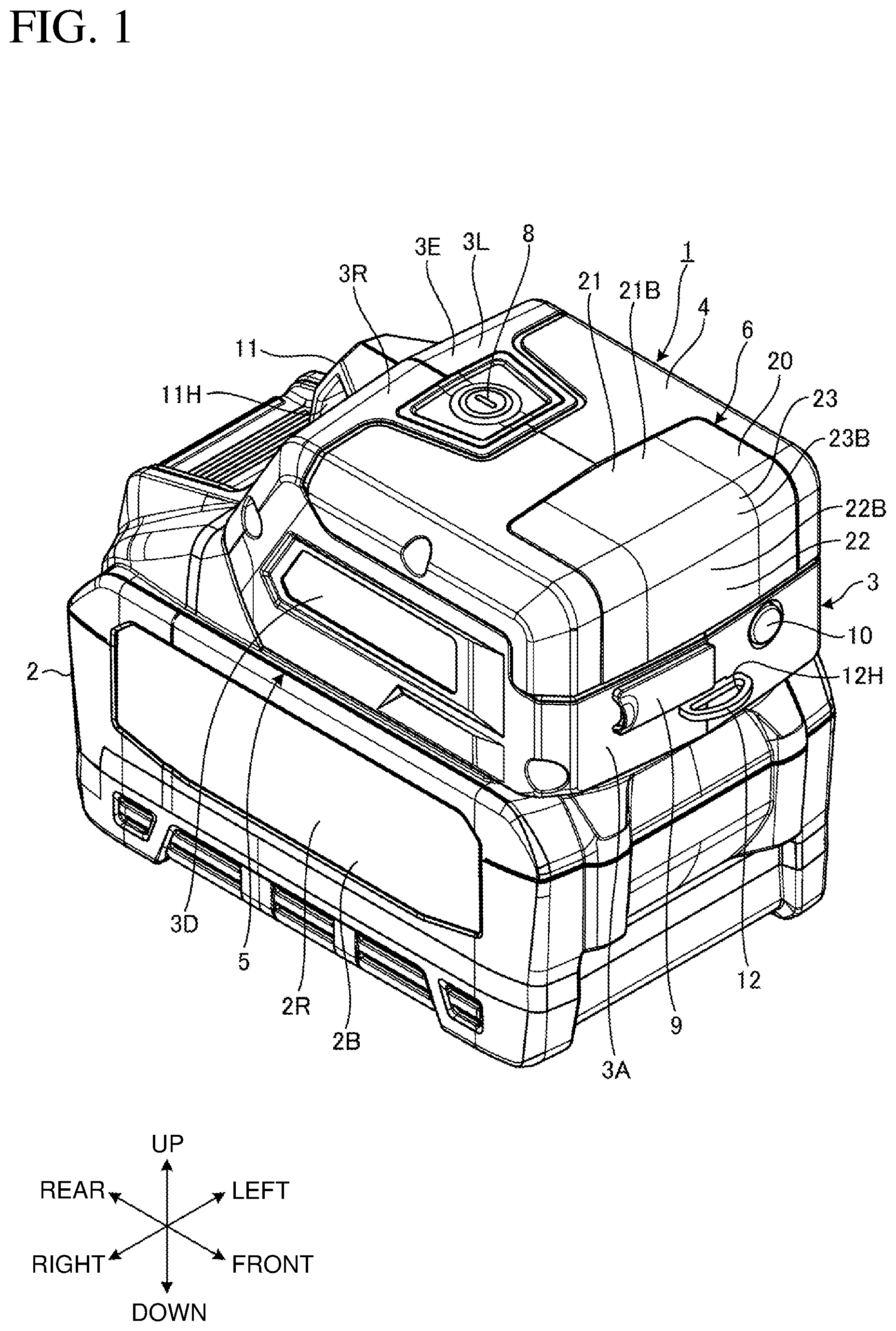
is a perspective view of an illumination apparatus with a battery pack according to an embodiment as viewed from the right front.
is a perspective view of the illumination apparatus with the battery pack according to the embodiment as viewed from the left rear.
is a right side view of the illumination apparatus with the battery pack according to the embodiment.
is a top view of the illumination apparatus with the battery pack according to the embodiment.
is a front view of the illumination apparatus with the battery pack according to the embodiment.
is a perspective view of the illumination apparatus according to the embodiment detached from the battery pack as viewed from the right front.
is a perspective view of the illumination apparatus according to the embodiment as viewed from below.
is an exploded perspective view of the illumination apparatus with the battery pack according to the embodiment as viewed from the right front.
is a cross-sectional perspective view of the illumination apparatus with the battery pack according to the embodiment as viewed from the right front.
is a cross-sectional side view of the illumination apparatus with the battery pack according to the embodiment.
is a perspective view of the illumination apparatus according to the embodiment with an output terminal cover being open.
is a perspective view of the illumination apparatus according to the embodiment with a second light-transmissive member attached as viewed from the right front.
is a perspective view of the second light-transmissive member and the illumination apparatus according to the embodiment as viewed from the right front.
is a perspective view of the second light-transmissive member and the illumination apparatus according to the embodiment as viewed from the left.
is a partial cross-sectional view of the illumination apparatus according to the embodiment with the second light-transmissive member attached.
is a view of the illumination apparatus according to the embodiment with a hanging member attached.
DETAILED DESCRIPTION
Although one or more embodiments of the present disclosure will now be described with reference to the drawings, the present disclosure is not limited to the embodiments. The components in the embodiments described below may be combined as appropriate. One or more components may be eliminated.
In the embodiments, the positional relationships between the components will be described using the directional terms such as front and rear (or frontward and rearward), right and left (or lateral), and up and down (or vertical). The terms indicate relative positions or directions with respect to the center of an illumination apparatus 1 . An axis extending in the front-rear direction is referred to as a front-rear axis for convenience. An axis extending in the lateral direction is referred to as a lateral axis for convenience. An axis extending in the vertical direction is referred to as a vertical axis for convenience. The front-rear axis and the lateral axis are orthogonal to each other. The lateral axis and the vertical axis are orthogonal to each other. The vertical axis and the front-rear axis are orthogonal to each other.
is a perspective view of the illumination apparatus 1 with a battery pack 2 according to an embodiment as viewed from the right front. is a perspective view of the illumination apparatus 1 with the battery pack 2 as viewed from the left rear. is a right side view of the illumination apparatus 1 and the battery pack 2 . is a top view of the illumination apparatus 1 and the battery pack 2 . is a front view of the illumination apparatus 1 and the battery pack 2 . is a perspective view of the illumination apparatus 1 detached from the battery pack 2 as viewed from the right front. is a perspective view of the illumination apparatus 1 as viewed from below. is an exploded perspective view of the illumination apparatus 1 with the battery pack 2 as viewed from the right front. is a cross-sectional perspective view of the illumination apparatus 1 with the battery pack 2 as viewed from the right front. is a cross-sectional side view of the illumination apparatus 1 and the battery pack 2 .
The illumination apparatus 1 according to the embodiment is a portable illumination apparatus that can be lifted and carried by a user of the illumination apparatus 1 alone. The illumination apparatus 1 is a rechargeable illumination apparatus that operates with power supplied from the rechargeable battery pack 2 .
The user can use the illumination apparatus 1 at a work site. When, for example, work is performed using a power tool at a work site, the illumination apparatus 1 is used to illuminate the power tool or a workpiece. The illumination apparatus 1 is used to illuminate, for example, the hand area of the user.
The illumination apparatus 1 includes a housing 3 , a housing cover 4 , a battery mount 5 , an illuminator 6 , a controller 7 , a power button 8 , an output terminal cover 9 , an output button 10 , a first coupler 11 , and a second coupler 12 .
The housing 3 accommodates at least a part of the illuminator 6 and the controller 7 . The housing 3 is formed from a synthetic resin. The housing 3 is formed from, for example, an acrylonitrile butadiene styrene (ABS) resin.
The housing 3 has an outer surface including a front surface 3 A, a rear surface 3 B, a left surface 3 C, a right surface 3 D, an upper surface 3 E, and a lower surface 3 F. Each of the front surface 3 A, the rear surface 3 B, the left surface 3 C, the right surface 3 D, the upper surface 3 E, and the lower surface 3 F is substantially flat. The front surface 3 A faces frontward. The rear surface 3 B faces rearward. The left surface 3 C faces leftward. The right surface 3 D faces rightward. The upper surface 3 E faces upward. The lower surface 3 F faces downward. The front surface 3 A is substantially orthogonal to the front-rear axis. The rear surface 3 B slopes downward toward the rear. The left surface 3 C is substantially orthogonal to the lateral axis. The right surface 3 D is substantially orthogonal to the lateral axis. The upper surface 3 E is substantially orthogonal to the vertical axis.
The upper end of the front surface 3 A and the front end of the upper surface 3 E are adjacent to each other. The left end of the front surface 3 A and the front end of the left surface 3 C are adjacent to each other. The right end of the front surface 3 A and the front end of the right surface 3 D are adjacent to each other. The left end of the upper surface 3 E and the upper end of the left surface 3 C are adjacent to each other. The right end of the upper surface 3 E and the upper end of the right surface 3 D are adjacent to each other. The upper end of the rear surface 3 B and the rear end of the upper surface 3 E are adjacent to each other. The left end of the rear surface 3 B and the rear end of the left surface 3 C are adjacent to each other. The right end of the rear surface 3 B and the rear end of the right surface 3 D are adjacent to each other.
The housing 3 includes a left housing 3 L and a right housing 3 R. The right housing 3 R is located on the right of the left housing 3 L. The left housing 3 L and the right housing 3 R are fastened together with multiple screws 3 S. The housing 3 includes a pair of housing halves.
The housing cover 4 covers at least a part of the outer surface of the housing 3 . The housing cover 4 is formed from an elastomer. The housing cover 4 in the embodiment covers a part of the front surface 3 A, a part of the left surface 3 C, a part of the right surface 3 D, and a part of the upper surface 3 E. The housing cover 4 covers the boundary between the front surface 3 A and the upper surface 3 E, the boundary between the front surface 3 A and the left surface 3 C, the boundary between the front surface 3 A and the right surface 3 D, the boundary between the upper surface 3 E and the left surface 3 C, and the boundary between the upper surface 3 E and the right surface 3 D.
The battery mount 5 is located on the lower surface 3 F of the housing 3 . The battery pack 2 is attached to the battery mount 5 in a detachable manner. The battery pack 2 includes a rechargeable battery, which is, for example, a rechargeable lithium-ion battery. The battery pack 2 is slidable. The battery pack 2 is a battery pack for a power tool.
The battery pack 2 includes a housing 2 B, a pair of slides 2 C, a protrusion 2 D, a release button 2 E, a pair of power terminals 2 F, and a pair of signal terminals 2 G. The housing 2 B has an attachment surface 2 A. The protrusion 2 D is supported movably on the housing 2 B. The release button 2 E is operable to move the protrusion 2 D. The housing 2 B has an internal space to accommodate a battery cell (not shown). The battery cell includes a rechargeable lithium-ion battery. The slides 2 C extend in the front-rear direction. The protrusion 2 D is supported movably by a spring. The protrusion 2 D protrudes from the attachment surface 2 A under an elastic force from the spring. The power terminals 2 F are located between the pair of slides 2 C. The signal terminals 2 G are located between the pair of power terminals 2 F.
The battery mount 5 includes guides 5 B, a lock 5 C, power terminals 5 D, and signal terminals 5 E.
The lower surface 3 F of the housing 3 faces the attachment surface 2 A of the battery pack 2 .
The guides 5 B guide the battery pack 2 in a predetermined guiding direction. The slides 2 C on the battery pack 2 are guided along the guides 5 B. The battery mount 5 includes two guides 5 B arranged in the lateral direction. The guides 5 B guide the battery pack 2 in the front-rear direction.
The lock 5 C is located on the lower surface 3 F of the housing 3 . The protrusion 2 D on the battery pack 2 is engaged with the lock 5 C. This locks the battery pack 2 on the battery mount 5 . In response to an operation on the release button 2 E, the battery pack 2 is unlocked from the battery mount 5 .
The power terminals 5 D are connected to the power terminals 2 F on the battery pack 2 . The signal terminals 5 E are connected to the signal terminals 2 G on the battery pack 2 . This allows the battery pack 2 to supply power to the illumination apparatus 1 .
To attach the battery pack 2 to the battery mount 5 , the user of the illumination apparatus 1 places the front ends of the slides 2 C on the battery pack 2 in contact with the rear ends of the guides 5 B on the battery mount 5 and then slides the battery pack 2 forward along the battery mount 5 . The battery pack 2 is guided along the guides 5 B to move forward. With the protrusion 2 D on the battery pack 2 engaged with the lock 5 C on the battery mount 5 , the battery pack 2 is locked on the battery mount 5 . In this manner, the battery pack 2 is slid forward along the battery mount 5 from the rear of the battery mount 5 and is attached to the battery mount 5 . The power terminals 2 F on the battery pack 2 are connected to the power terminals 5 D on the battery mount 5 to supply power from the battery pack 2 to the illumination apparatus 1 .
To detach the battery pack 2 from the battery mount 5 , the user of the illumination apparatus 1 operates the release button 2 E. The protrusion 2 D is thus disengaged from the lock 5 C. This unlocks the battery pack 2 from the battery mount 5 . The battery pack 2 is then slid backward and detached from the battery mount 5 .
The illumination apparatus 1 has a smaller dimension than the battery pack 2 in the lateral direction. With the battery pack 2 attached to the battery mount 5 , the left surface 3 C of the housing 3 does not protrude leftward from a left surface 2 L of the housing 2 B. The right surface 3 D of the housing 3 does not protrude rightward from a right surface 2 R of the housing 2 B. More specifically, each of the left surface 3 C and the right surface 3 D of the housing 3 orthogonal to each of the front surface 3 A and the upper surface 3 E does not protrude outward from the side surfaces of the housing 2 B in the battery pack 2 .
The illuminator 6 includes a circuit board 13 , a circuit board 14 , multiple light emitters 15 , multiple light emitters 16 , a heat sink 17 , a reflector 18 , a reflector 19 , and a light-transmissive member 20 . The light emitters 15 are mounted on the circuit board 13 . The light emitters 16 are mounted on the circuit board 14 . The heat sink 17 is connected to the circuit board 13 and to the circuit board 14 . The reflector 18 partially surrounds the light emitters 15 . The reflector 19 partially surrounds the light emitters 16 . Light emitted from at least the light emitters 15 or the light emitters 16 passes through the light-transmissive member 20 .
The circuit board 13 has a surface facing upward. The circuit board 14 has a surface facing frontward.
The light emitters 15 operate with power supplied from the battery pack 2 . The light emitters 15 are mounted on the surface (upper surface) of the circuit board 13 . The light emitters 15 are light-emitting diodes (LEDs). The light emitters 15 have light-emitting surfaces facing upward. The light emitters 15 (four in the present embodiment) are at intervals in the lateral direction.
The light emitters 16 operate with power supplied from the battery pack 2 . The light emitters 16 are mounted on the surface (front surface) of the circuit board 14 . The light emitters 16 are LEDs. The light emitters 16 have light-emitting surfaces facing frontward. The light emitters 16 (four in the present embodiment) are at intervals in the lateral direction.
The heat sink 17 dissipates heat from the circuit board 13 and from the circuit board 14 to the surrounding area. The heat sink 17 is formed from a metal. The heat sink 17 is formed from, for example, aluminum. The heat sink 17 includes a first support 17 A and a second support 17 B. The first support 17 A is connected to the back surface (lower surface) of the circuit board 13 . The second support 17 B is connected to the back surface (rear surface) of the circuit board 14 .
The reflector 18 reflects light emitted from the light emitters 15 . The reflector 19 reflects light emitted from the light emitters 16 . The reflector 18 and the reflector 19 each include a body and a reflective film on a surface of the body. The body is formed from, for example, a polycarbonate resin. The reflective film is a metal film. The reflective film contains, for example, silver. The reflective film is a layer of plating on the body. The surface of the reflective film on the reflector 18 is a reflective surface that reflects light emitted from the light emitters 15 . The surface of the reflective film on the reflector 19 is a reflective surface that reflects light emitted from the light emitters 16 .
The reflective surface of the reflector 18 surrounds the light emitters 15 . The reflective surface of the reflector 18 reflects light emitted from the light emitters 15 to allow at least part of the light to travel upward. The reflector 18 is connected to the surface (upper surface) of the circuit board 13 .
The reflective surface of the reflector 19 surrounds the light emitters 16 . The reflective surface of the reflector 19 reflects light emitted from the light emitters 16 to allow at least part of the light to travel forward. The reflector 19 is connected to the surface (front surface) of the circuit board 14 .
The reflector 18 , the circuit board 13 , and the first support 17 A in the heat sink 17 are fastened with two screws 18 S. The reflector 19 , the circuit board 14 , and the second support 17 B in the heat sink 17 are fastened with two screws 19 S. The circuit board 13 , the circuit board 14 , the heat sink 17 , the reflector 18 , and the reflector 19 are held between the left housing 3 L and the right housing 3 R. The circuit board 13 , the circuit board 14 , the heat sink 17 , the reflector 18 , and the reflector 19 are fixed to the housing 3 .
The light-transmissive member 20 covers the light emitters 15 and the light emitters 16 . The light-transmissive member 20 is transmissive to light. At least part of light from the light emitters 15 passes through the light-transmissive member 20 . The light-transmissive member 20 is a diffuser that diffuses light emitted from the light emitters 15 to the surrounding area. At least part of light from the light emitters 16 passes through the light-transmissive member 20 . The light-transmissive member 20 is a diffuser that diffuses light emitted from the light emitters 16 to the surrounding area. The light-transmissive member 20 protects the light emitters 15 and the light emitters 16 .
The light-transmissive member 20 is formed from a light-diffusing resin. For light with high directivity emitted from the light emitters 15 and the light emitters 16 , the light-transmissive member 20 allows light traveling straight to be less noticeable, thus reducing unevenness in luminance. The illuminator 6 including the light-transmissive member 20 can illuminate the surrounding area with a uniform illuminance distribution.
The light-transmissive member 20 may be formed from a transparent synthetic resin or glass.
The housing 3 has the outer surface including the upper surface 3 E and the front surface 3 A. The front surface 3 A adjacent to the upper surface 3 E faces in a direction different from the direction in which the upper surface 3 E faces. The light-transmissive member 20 is supported by the housing 3 . The light-transmissive member 20 extends on the upper surface 3 E and on the front surface 3 A of the housing 3 .
The housing 3 has the outer surface including the left surface 3 C and the right surface 3 D each adjacent to the upper surface 3 E and the front surface 3 A. The left surface 3 C faces in a direction different from the directions in which the upper surface 3 E and the front surface 3 A face. The right surface 3 D faces in a direction different from the directions in which the upper surface 3 E and the front surface 3 A face. The light-transmissive member 20 does not extend to the left surface 3 C and the right surface 3 D.
The light-transmissive member 20 includes a first light transmitter 21 , a second light transmitter 22 , and a third light transmitter 23 . The first light transmitter 21 is adjacent to the upper surface 3 E. The second light transmitter 22 is adjacent to the front surface 3 A. The third light transmitter 23 connects the first light transmitter 21 and the second light transmitter 22 .
The first light transmitter 21 has an incident surface 21 A and an emission surface 21 B. Light from the light emitters 15 is incident on the incident surface 21 A. Light from the light emitters 15 is emitted through the emission surface 21 B. The first light transmitter 21 is substantially a flat plate. The incident surface 21 A and the emission surface 21 B are both substantially flat. The incident surface 21 A and the emission surface 21 B are parallel to each other. The incident surface 21 A and the emission surface 21 B are both substantially orthogonal to the vertical axis. In the embodiment, as shown in , the emission surface 21 B is curved with its middle portion in the lateral direction slightly expanding upward.
The incident surface 21 A faces downward. The emission surface 21 B faces upward. The emission surface 21 B is adjacent to the upper surface 3 E of the housing 3 . The upper surface 3 E of the housing 3 partially surrounds the emission surface 21 B. The emission surface 21 B faces in the same direction as the upper surface 3 E of the housing 3 .
The second light transmitter 22 has an incident surface 22 A and an emission surface 22 B. Light from the light emitters 16 is incident on the incident surface 22 A. Light from the light emitters 16 is emitted through the emission surface 22 B. The second light transmitter 22 is substantially a flat plate. The incident surface 22 A and the emission surface 22 B are both substantially flat. The incident surface 22 A and the emission surface 22 B are parallel to each other. The incident surface 22 A and the emission surface 22 B are both substantially orthogonal to the front-rear axis. In the embodiment, as shown in , the emission surface 22 B is curved with its middle portion in the lateral direction slightly expanding frontward.
The incident surface 22 A faces rearward. The emission surface 22 B faces frontward. The emission surface 22 B is adjacent to the front surface 3 A of the housing 3 . The front surface 3 A of the housing 3 partially surrounds the emission surface 22 B. The emission surface 22 B faces in the same direction as the front surface 3 A of the housing 3 .
The angle between the first light transmitter 21 and the second light transmitter 22 is substantially a right angle. The angle between the first light transmitter 21 and the second light transmitter 22 may be the smaller one of the angle between the incident surface 21 A and the incident surface 22 A and the angle between the emission surface 21 B and the emission surface 22 B.
The third light transmitter 23 has an incident surface 23 A and an emission surface 23 B. Light from the light emitters 15 , from the light emitters 16 , or from both the light emitters 15 and the light emitters 16 is incident on the incident surface 23 A. Light from the light emitters 15 , from the light emitters 16 , or from both the light emitters 15 and the light emitters 16 is emitted through the emission surface 23 B. The third light transmitter 23 bends to connect the front end of the first light transmitter 21 and the upper end of the second light transmitter 22 . The incident surface 23 A connects the front end of the incident surface 21 A and the upper end of the incident surface 22 A. The emission surface 23 B connects the front end of the emission surface 21 B and the upper end of the emission surface 22 B.
The incident surface 23 A is curved in a cross section orthogonal to each of the incident surface 21 A and the incident surface 22 A. The incident surface 23 A is recessed upward and frontward in an arc in the cross section orthogonal to each of the incident surface 21 A and the incident surface 22 A.
The emission surface 23 B is curved in a cross section orthogonal to each of the emission surface 21 B and the emission surface 22 B. The emission surface 23 B is curved upward and frontward in an arc in the cross section orthogonal to each of the emission surface 21 B and the emission surface 22 B.
The light emitters 15 are located below the first light transmitter 21 . The light emitters 15 face the incident surface 21 A of the first light transmitter 21 . Light emitted from the light emitters 15 is incident on the incident surface 21 A and is emitted through the emission surface 21 B. At least part of the light incident on the incident surface 21 A is emitted through the emission surface 23 B of the third light transmitter 23 .
The light emitters 16 are located at the rear of the second light transmitter 22 . The light emitters 16 face the incident surface 22 A of the second light transmitter 22 . Light emitted from the light emitters 16 is incident on the incident surface 22 A and is emitted through the emission surface 22 B. At least part of the light incident on the incident surface 22 A is emitted through the emission surface 23 B of the third light transmitter 23 .
At least part of light emitted from the light emitters 15 is incident on the incident surface 23 A. At least part of light emitted from the light emitters 16 is incident on the incident surface 23 A. Light incident on the incident surface 23 A is emitted through the emission surface 23 B.
The light emitters 15 are attached to the circuit board 13 . The light emitters 16 are attached to the circuit board 14 . The circuit board 13 and the circuit board 14 are orthogonal to each other in the cross section orthogonal to the emission surface 21 B and to the emission surface 22 B. The light emitters 15 are mounted on the upper surface of the circuit board 13 serving as a mount surface. The light emitters 16 are mounted on the front surface of the circuit board 14 serving as a mount surface. The upper surface of the circuit board 13 and the front surface of the circuit board 14 are substantially orthogonal to each other in the cross section orthogonal to the emission surface 21 B and to the emission surface 22 B.
The circuit board 13 and the circuit board 14 may be in contact with each other. The circuit board 13 and the circuit board 14 may be located across a space with a dimension less than or equal to the thicknesses of the circuit board 13 and the circuit board 14 .
The controller 7 controls at least the light emitters 15 and the light emitters 16 . The controller 7 includes a circuit board and multiple electronic components mounted on the circuit board. The electronic components include, for example, a microcomputer. In the embodiment, the four light emitters 15 are turned on or off simultaneously. The four light emitters 16 are turned on or off simultaneously. The light emitters 15 and the light emitters 16 can be turned on simultaneously. The light emitters 15 and the light emitters 16 can be turned on separately. The controller 7 switches the light emitters between a first illuminating state, a second illuminating state, a fully illuminating state, and a non-illuminating state. In the first illuminating state, the light emitters 15 are turned on, and the light emitters 16 are turned off. In the second illuminating state, the light emitters 16 are turned on, and the light emitters 15 are turned off. In the fully illuminating state, the light emitters 15 and the light emitters 16 are both turned on. In the non-illuminating state, the light emitters 15 and the light emitters 16 are both turned off.
The power button 8 is operable by the user to turn on or off the light emitters 15 and the light emitters 16 . The power button 8 is at least partially located on the upper surface 3 E of the housing 3 . As shown in , the power button 8 includes a button 8 A and a rod 8 B. The button 8 A is located on the upper surface 3 E of the housing 3 . The rod 8 B extends downward from the button 8 A. A switching element 7 A faces the lower end of the rod 8 B. The switching element 7 A is mounted on a surface of a circuit board in the controller 7 . When the user presses the button 8 A downward from above, the rod 8 B pushes the switching element 7 A. This causes the controller 7 to turn on or off the light emitters 15 and the light emitters 16 . A coil spring 8 C surrounds the rod 8 B. The coil spring 8 C generates an elastic force for moving the power button 8 upward. When the user releases the power button 8 , the power button 8 returns to its initial position under an elastic force from the coil spring 8 C.
The operations on the power button 8 include a short-press operation and a long-press operation. The short-press operation refers to pressing the power button 8 for a short time. The long-press operation refers to pressing the power button 8 for a long time.
In the fully illuminating state, a short-press operation on the power button 8 switches the fully illuminating state to the first illuminating state. In the first illuminating state, a short-press operation on the power button 8 switches the first illuminating state to the second illuminating state. In the second illuminating state, a short-press operation on the power button 8 switches the second illuminating state to the non-illuminating state. In each of the fully illuminating state, the first illuminating state, and the second illuminating state, a long-press operation on the power button 8 switches the illuminating state to the non-illuminating state.
In the non-illuminating state, a short-press operation on the power button 8 switches the non-illuminating state to one of the fully illuminating state, the first illuminating state, or the second illuminating state. The controller 7 stores the illuminating state immediately before the non-illuminating state. For example, for the illuminating state immediately before the non-illuminating state being the fully illuminating state, a short-press operation on the power button 8 in the non-illuminating state switches the non-illuminating state to the fully illuminating state. For the illuminating state immediately before the non-illuminating state being the first illuminating state, a short-press operation on the power button 8 in the non-illuminating state switches the non-illuminating state to the first illuminating state. For the illuminating state immediately before the non-illuminating state being the second illuminating state, a short-press operation on the power button 8 in the non-illuminating state switches the non-illuminating state to the second illuminating state.
As shown in to 11 , the illumination apparatus 1 may be used with the battery pack 2 under the illumination apparatus 1 . The illumination apparatus 1 may be used with the lower surface of the battery pack 2 facing any support surface such as the floor at a work site or the upper surface of a work table.
The illumination apparatus 1 has a smaller dimension than the battery pack 2 in the lateral direction. The left surface 3 C of the housing 3 does not protrude leftward from the left surface 2 L of the housing 2 B. The right surface 3 D of the housing 3 does not protrude rightward from the right surface 2 R of the housing 2 B. More specifically, the left surface 3 C and the right surface 3 D of the housing 3 orthogonal to the front surface 3 A and the upper surface 3 E do not protrude outward from the side surfaces of the housing 2 B. The illumination apparatus 1 may thus be used with, for example, the left surface 2 L of the battery pack 2 and the left surface 3 C of the housing 3 facing a support surface. The illumination apparatus 1 may be used with, for example, the right surface 2 R of the battery pack 2 and the right surface 3 D of the housing 3 facing a support surface. In other words, the illumination apparatus 1 in the state shown in may be, for example, placed on its side in use.
is a perspective view of the illumination apparatus 1 according to the embodiment with the output terminal cover 9 being open. The output terminal cover 9 covers an output terminal 24 . The output terminal cover 9 is located on the front surface 3 A of the housing 3 . The output terminal 24 in the embodiment is a universal serial bus (USB) terminal. The output terminal 24 outputs power from the battery pack 2 . The illumination apparatus 1 can be used to charge, for example, a rechargeable battery in an electronic device such as a mobile terminal. The output terminal 24 may be connected to the electronic device with a USB cable to charge the rechargeable battery in the electronic device with power output from the battery pack 2 through the output terminal 24 .
The output button 10 is operable by the user to switch between outputting and stopping power from the output terminal 24 . The output button 10 is located on the front surface 3 A of the housing 3 . When the output button 10 is pressed once with no power being output from the output terminal 24 , power is output from the output terminal 24 to the rechargeable battery in the electronic device through the USB cable, starting charging of the rechargeable battery. When the output button 10 is pressed once in this state, the output of power from the output terminal 24 is stopped, stopping charging of the rechargeable battery. In the embodiment, the output button 10 incorporates a light emitter. The light emitter in the output button 10 is turned on while power is being output from the output terminal 24 . The light emitter in the output button 10 is turned off when no power is being output from the output terminal 24 .
is a perspective view of the illumination apparatus 1 according to the embodiment with a second light-transmissive member 25 attached as viewed from the right front. is a perspective view of the second light-transmissive member 25 and the illumination apparatus 1 as viewed from the right front. is a perspective view of the second light-transmissive member 25 and the illumination apparatus 1 as viewed from the left. is a partial cross-sectional view of the illumination apparatus 1 with the second light-transmissive member 25 attached.
The light-transmissive member 20 may be covered with the second light-transmissive member 25 . The second light-transmissive member 25 changes the color of light emitted through the light-transmissive member 20 and allows emission of light with the changed color. The second light-transmissive member 25 is formed from a synthetic resin containing a colored pigment. The second light-transmissive member 25 has a warm color such as orange, yellow, or red. The second light-transmissive member 25 allows emission of light with a warm color. The second light-transmissive member 25 may have a cool color such as blue or a neutral color such as green or purple, rather than a warm color. In other words, light emitted through the second light-transmissive member 25 may be light with a cool color such as blue or light with a neutral color such as green or purple, rather than light with a warm color. The second light-transmissive member 25 may reduce the glare of light emitted through the light-transmissive member 20 .
The second light-transmissive member 25 includes hook portions 25 A that can be hooked on at least parts of the housing 3 . The housing 3 includes locks 4 A engaged with the second light-transmissive member 25 covering the light-transmissive member 20 . The locks 4 A in the embodiment are located at the boundary between the housing 3 and the housing cover 4 . With the hook portions 25 A hooked on the locks 4 A, the second light-transmissive member is attached to the housing 3 to cover the light-transmissive member 20 . With the hook portions 25 A unhooked from the locks 4 A, the second light-transmissive member 25 can be detached from the housing 3 .
The first coupler 11 is located on the rear surface 3 B of the housing 3 opposite to the front surface 3 A. The first coupler 11 protrudes rearward from the rear surface 3 B. The first coupler 11 is annular. The first coupler 11 has an opening 11 H extending through the first coupler 11 in the lateral direction. The first coupler 11 is formed from a synthetic resin.
The second coupler 12 is located on the front surface 3 A of the housing 3 . The second coupler 12 protrudes frontward from the front surface 3 A. The second coupler 12 is annular. The second coupler 12 has an opening 12 H extending through second coupler 12 in the vertical direction. The second coupler 12 is formed from a metal.
A hanging member 26 is attachable to the first coupler 11 and the second coupler 12 .
shows the illumination apparatus 1 according to the embodiment with the hanging member 26 attached. The hanging member 26 includes a belt 26 A and a hook 26 B. The belt 26 A is attached to the first coupler 11 . The hook 26 B is connected to a part of the belt 26 A. In the example shown in , a part of the belt 26 A is attached to the first coupler 11 , and another part of the belt 26 A is attached to the second coupler 12 . The belt 26 A is placed through the opening 11 H in the first coupler 11 and is thus attached to the first coupler 11 . The belt 26 A is placed thorough the opening 12 H in the second coupler 12 and is thus attached to the second coupler 12 . The hook 26 B is hung on a structure 27 at a work site. The illumination apparatus 1 and the battery pack 2 are thus hung from the structure 27 with the hanging member 26 . The illumination apparatus 1 hung with the second light transmitter 22 facing downward can illuminate a target from above.
The illumination apparatus 1 according to the embodiment includes the housing 3 , the light emitters 15 and 16 operable with power supplied from the battery pack 2 , and the light-transmissive member 20 supported by the housing 3 and transmissive to at least part of light from the light emitters 15 and 16 . The housing 3 has the outer surface including the upper surface 3 E being a first outer surface and the front surface 3 A being a second outer surface. The front surface 3 A is adjacent to the upper surface 3 E and faces in a direction different from a direction in which the upper surface 3 E faces. The light-transmissive member 20 extends on the upper surface 3 E and on the front surface 3 A.
In the above structure, the light-transmissive member 20 extends on the upper surface 3 E and on the front surface 3 A of the housing 3 . This allows light emitted from the light emitters 15 to illuminate the space facing the upper surface 3 E, and light emitted from the light emitters 16 to illuminate the space facing the front surface 3 A. The upper surface 3 E and the front surface 3 A face in different directions. This allows light emitted from the light emitters 15 and the light emitters 16 to illuminate a wide area. The light-transmissive member being a single piece allows light emitted from the light emitters 15 and the light emitters 16 to efficiently illuminate the surrounding area of the light-transmissive member 20 . The illumination apparatus 1 can thus efficiently illuminate a wide area.
The light-transmissive member 20 in the embodiment includes the first light transmitter 21 adjacent to the upper surface 3 E, the second light transmitter 22 adjacent to the front surface 3 A, and the third light transmitter 23 connecting the first light transmitter 21 and the second light transmitter 22 .
This allows light emitted from the light emitters 15 to efficiently illuminate the surrounding area of the light-transmissive member 20 through the first light transmitter 21 and the third light transmitter 23 , and light emitted from the light emitters 16 to efficiently illuminate the surrounding area of the light-transmissive member 20 through the second light transmitter 22 and the third light transmitter 23 .
The first light transmitter 21 includes a flat plate. The second light transmitter 22 includes a flat plate. The third light transmitter 23 bends and connects the first light transmitter 21 and the second light transmitter 22 .
This allows light emitted from the light emitters 15 to efficiently illuminate the surrounding area of the light-transmissive member 20 through the first light transmitter 21 and the third light transmitter 23 , and light emitted from the light emitters 16 to efficiently illuminate the surrounding area of the light-transmissive member 20 through the second light transmitter 22 and the third light transmitter 23 .
In the embodiment, the first light transmitter 21 has the emission surface 21 B (first emission surface 21 B) adjacent to the upper surface 3 E and facing in the same direction as the upper surface 3 E. The second light transmitter 22 has the emission surface 22 B (second emission surface 22 B) adjacent to the front surface 3 A and facing in the same direction as the front surface 3 A. The third light transmitter 23 has the emission surface 23 B (third emission surface 23 B) connecting the emission surface 21 B and the emission surface 22 B and curved in the cross section orthogonal to each of the emission surface 21 B and the emission surface 22 B.
This allows light emitted from the light emitters 15 to efficiently illuminate the surrounding area of the light-transmissive member 20 through the first light transmitter 21 and the third light transmitter 23 , and light emitted from the light emitters 16 to efficiently illuminate the surrounding area of the light-transmissive member 20 through the second light transmitter 22 and the third light transmitter 23 .
The light emitters 15 each being a first light emitter face the incident surface 21 A of the first light transmitter 21 . The light emitters 16 each being a second light emitter face the incident surface 22 A of the second light transmitter 22 .
The illumination apparatus 1 can thus be easily assembled.
The illumination apparatus 1 according to the embodiment includes the circuit board 13 being a first substrate on which the light emitters 15 are attached, and the circuit board 14 being a second substrate on which the light emitters 16 are attached.
The circuit board 13 and the circuit board 14 are orthogonal to each other in the cross section orthogonal to each of the emission surface 21 B and the emission surface 22 B.
In this structure, the light emitters 15 and the light emitters 16 are located adjacent to the third light transmitter 23 at the corner of the light-transmissive member 20 , thus allowing the illumination apparatus 1 to uniformly illuminate a wide area. The illumination apparatus 1 can reduce, for example, darkness of the area around the third light transmitter 23 at the corner of the light-transmissive member 20 .
The housing 3 in the embodiment includes the battery mount 5 to which the battery pack 2 is attachable.
The light emitters 15 and the light emitters 16 thus operate with power supplied from the battery pack 2 attached to the battery mount 5 .
The housing 3 in the embodiment includes the locks 4 A engaged with the second light-transmissive member 25 covering the light-transmissive member 20 .
The second light-transmissive member 25 is thus locked on the housing 3 .
The light-transmissive member 20 in the embodiment includes the diffuser.
The light-transmissive member 20 including the diffuser that diffuses at least part of light from the light emitters 15 and the light emitters 16 allows the illumination apparatus 1 to uniformly illuminate a wider area.
In the embodiment, the outer surface of the housing 3 includes the left surface 3 C and the right surface 3 D each being a third outer surface orthogonal to each of the upper surface 3 E and the front surface 3 A. The left surface 3 C does not protrude leftward (outward) from the left surface 2 L being one side surface of the battery pack 2 . The right surface 3 D does not protrude rightward (outward) from the right surface 2 R being another side surface of the battery pack 2 .
The illumination apparatus 1 can thus be placed on a support surface with a side surface of the battery pack 2 facing the support surface.
In the embodiment, the left surface 3 C and the right surface 3 D each being the third outer surface are adjacent to the upper surface 3 E and the front surface 3 A. The light-transmissive member 20 does not extend to the left surface 3 C and the right surface 3 D.
This structure does not allow light emitted from the light emitters 15 and the light emitters 16 to illuminate the spaces facing the left surface 3 C and the right surface 3 D, although the light illuminates the spaces facing the upper surface 3 E and the front surface 3 A. This reduces illumination of unintended spaces with light emitted from the light emitters 15 and the light emitters 16 .
In the embodiment, the outer surface of the housing 3 includes the rear surface 3 B opposite to the front surface 3 A. The housing 3 includes, on the rear surface 3 B, the first coupler 11 to which the hanging member 26 is attachable.
The housing 3 is hung from the hanging member 26 with the front surface 3 A facing downward, thus allowing light emitted from the light emitters 15 and the light emitters 16 to illuminate the space below the illumination apparatus 1 .
The housing 3 in the embodiment includes, on the front surface 3 A, the second coupler 12 to which the hanging member 26 is attachable.
This allows the hanging member 26 to hang the housing 3 more stably.
REFERENCE SIGNS LIST
•
• 1 illumination apparatus • 2 battery pack • 2 A attachment surface • 2 B housing • 2 C slide • 2 D protrusion • 2 E release button • 2 F power terminal • 2 G signal terminal • 2 L left surface • 2 R right surface • 3 housing • 3 A front surface • 3 B rear surface • 3 C left surface • 3 D right surface • 3 E upper surface • 3 F lower surface • 3 L left housing • 3 R right housing • 3 S screw • 4 housing cover • 4 A lock • 5 battery mount • 5 B guide • 5 C lock • 5 D power terminal • 5 E signal terminal • 6 illuminator • 7 controller • 7 A switching element • 8 power button • 8 A button • 8 B rod • 8 C coil spring • 9 output terminal cover • 10 output button • 11 first coupler • 11 H opening • 12 second coupler • 12 H opening • 13 circuit board • 14 circuit board • 15 light emitter (first light emitter) • 16 light emitter (second light emitter) • 17 heat sink • 17 A first support • 17 B second support • 18 reflector • 18 S screw • 19 reflector • 19 S screw • 20 light-transmissive member • 21 first light transmitter • 21 A incident surface • 21 B emission surface • 22 second light transmitter • 22 A incident surface • 22 B emission surface • 23 third light transmitter • 23 A incident surface • 23 B emission surface • 24 output terminal • 25 second light-transmissive member • 25 A hook portion • 26 hanging member • 26 A belt • 26 B hook • 27 structure
Figures (16)
Citations
This patent cites (12)
- US5169225
- US6814461
- US9923249
- US11472016
- US20040174699
- US20070278995
- US20150029701
- US20160172722
- US20160223185
- US102022112869
- US6982732
- USWO-2017147019