Joint Member, Method for Producing Joint Member, and Method for Connecting Flexible Tube to Joint Member
Abstract
A joint member includes a joint main body configured to include a flow path portion formed and an opening portion communicating with the flow path portion, and a tube member configured to include an end portion inserted into the opening portion of the joint main body and joined to the joint main body by brazing. The joint main body includes a step portion on which the end portion of the tube member inserted into the opening portion abuts. The tube member includes an annular recessed portion recessed from an outer peripheral surface of the tube member and formed on a flexible tube side with respect to an end surface on a joint main body side.
Claims (6)
1. A joint member to which a flexible tube is to be connected, the joint member comprising: a joint main body configured to include a flow path portion formed therein and an opening portion with an inner diameter larger than an inner diameter of the flow path portion and communicating with the flow path portion; and a tube member configured to include an end portion inserted into the opening portion of the joint main body and joined to the joint main body by brazing, and to be inserted into the flexible tube, wherein the flexible tube and the joint main body are connected to each other via the tube member and are otherwise separated from each other, wherein the joint main body comprises a step portion formed between the opening portion and the flow path portion and on which the end portion of the tube member inserted into the opening portion abuts, and the tube member comprises an annular recessed portion recessed from an outer peripheral surface of the tube member and formed on a flexible tube side with respect to an end surface on a joint main body side.
6. A method for connecting the flexible tube to a joint member to which a flexible tube is to be connected, the joint member including: a joint main body configured to include a flow path portion formed therein and an opening portion with an inner diameter larger than an inner diameter of the flow path portion and communicating with the flow path portion; and a tube member configured to include an end portion inserted into the opening portion of the joint main body and joined to the joint main body by brazing, and to be inserted into the flexible tube, wherein the joint main body comprises a step portion formed between the opening portion and the flow path portion and on which the end portion of the tube member inserted into the opening portion abuts, and the tube member comprises an annular recessed portion recessed from an outer peripheral surface of the tube member and formed on a flexible tube side with respect to an end surface on a joint main body side, the method comprising: inserting the tube member into a tube end of the flexible tube up to the annular recessed portion; and fixing the flexible tube from an outside in a radial direction with an annular clamp member at a position where the flexible tube and the tube member overlap.
Show 4 dependent claims
2. The joint member according to claim 1 , wherein the annular recessed portion is formed on the outer peripheral surface of the tube member and is formed at a position away from the end surface on the joint main body side.
3. The joint member according to claim 1 , wherein a brazing material used for brazing the joint main body and the tube member spreads within a range from the end surface of the tube member on the joint main body side to a wall portion in the annular recessed portion on a side away from the joint main body side.
4. The joint member according to claim 1 , wherein the flow path portion comprises a throttle portion, and wherein the throttle portion has an inner diameter smaller than an inner diameter of the flexible tube.
5. A method for producing the joint member according to claim 1 , the method comprising: inserting the end portion of the tube member into the opening portion of the joint main body and causing the end portion of the tube member to abut on the step portion; and joining the joint main body and the end portion of the tube member by brazing.
Full Description
Show full text →
This application is a National Stage Entry of PCT/JP2020/041051 filed on Nov. 2, 2020, which claims priority from Japanese Patent Application 2019-205339 filed on Nov. 13, 2019, the contents of all of which are incorporated herein by reference, in their entirety.
TECHNICAL FIELD
The present invention relates to a joint member, a method for producing the joint member, and a method for connecting a flexible tube to the joint member.
BACKGROUND ART
When connecting tubes through which a fluid flows, joint members that can be attached to and detached from each other are provided at the end portions of both tubes. Both tubes are connected to each other by engaging the joint member provided at an end portion of one of the tubes and the joint member provided at an end portion of the other of the tubes with each other.
Patent Document 1 discloses a configuration in which one tube is expanded and the other tube is inserted into one tube to connect the tubes to each other at the connecting portion of the tubes (refrigerant tubes) through which a cooling medium of a cooling apparatus flows. Patent Document 1 discloses a configuration in which a plurality of slits formed in an annular direction are provided on both contact surfaces of the connecting portion of the tubes. When welding tubes to each other, a brazing material accumulates in these slits, so that the tubes are joined to each other.
PRIOR ART DOCUMENT
Patent Document
Patent Document 1: Japanese Unexamined Patent Application, First Publication No. 2003-130528
SUMMARY
Problems to be Solved by the Invention
Incidentally, the joint member may be configured to include separate parts of a joint main body and a tube member to which the tube is to be connected.
However, when the joint main body and the tube member are joined by brazing as disclosed in Patent Document 1, the range in which the brazing material protrudes from a joint portion may vary.
An example object of the present invention is to provide a joint member, a method for producing the joint member, and a method for connecting a flexible tube to the joint member that solve the above-described problems.
Means for Solving the Problems
A joint member according to a first example aspect of the present invention is a joint member to which a flexible tube is to be connected, and the joint member includes a joint main body configured to include a flow path portion formed therein and an opening portion with an inner diameter larger than an inner diameter of the flow path portion and communicating with the flow path portion, and a tube member configured to include an end portion inserted into the opening portion of the joint main body and joined to the joint main body by brazing, and to be inserted into the flexible tube. The joint main body includes a step portion formed between the opening portion and the flow path portion and on which the end portion of the tube member inserted into the opening portion abuts. The tube member includes an annular recessed portion recessed from an outer peripheral surface of the tube member and formed on a flexible tube side with respect to an end surface on a joint main body side.
A method for producing the joint member according to a second example aspect of the present invention is a method for producing the joint member described above, and the method includes inserting the end portion of the tube member into the opening portion of the joint main body and causing the end portion of the tube member to abut on the step portion, and joining the joint main body and the end portion of the tube member by brazing.
A method for connecting a flexible tube to a joint member according to a third example aspect of the present invention, there is provided a method for connecting the flexible tube to the joint member described above, and the method includes inserting the tube member into a tube end of the flexible tube up to the annular recessed portion, and fixing the flexible tube from an outside in a radial direction with an annular clamp member at a position where the flexible tube and the tube member overlap.
Example Advantageous Effects of Invention
According to the above-described first to third example aspects, the range in which the brazing material protrudes from the joint portion is unlikely to vary.
BRIEF DESCRIPTION OF DRAWINGS
is a diagram showing a minimum configuration of a joint member according to a first example embodiment of the present invention.
is a diagram showing a minimum procedure of a method for producing a joint member according to a second example embodiment of the present invention.
is a diagram showing a minimum procedure of a method for connecting a flexible tube to a joint member according to a third example embodiment of the present invention.
is a cross-sectional view showing the joint member and the flexible tube connected by the method for connecting the flexible tube to the joint member according to the third example embodiment of the present invention.
is a perspective view showing a joint member according to a fourth example embodiment of the present invention.
is a cross-sectional view showing the joint member according to the fourth example embodiment of the present invention.
is a cross-sectional view of a tube member constituting the joint member according to the fourth example embodiment of the present invention.
is a cross-sectional view showing a state in which a flexible tube is connected to the joint member according to the fourth example embodiment of the present invention.
is a cross-sectional view showing a state in which the tube member is inserted inside a tube end of the flexible tube by the method for connecting the flexible tube to the joint member according to the fourth example embodiment of the present invention.
is a diagram showing a normal distribution of measured values of wettability spread dimensions of a brazing material in an example of the present invention.
is a diagram showing a normal distribution of measured values of the amount of elongation of the flexible tube when the flexible tube is tightened with a clamp member in the example of the present invention.
is a cross-sectional view showing a modification example of the joint member according to an example embodiment of the present invention.
EXAMPLE EMBODIMENT
A plurality of example embodiments of the present invention will be described below with reference to the drawings.
First Example Embodiment
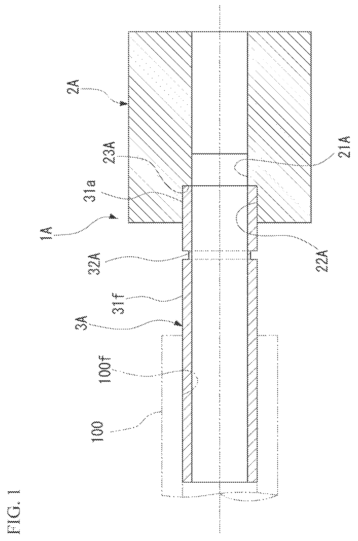
is a diagram showing a minimum configuration of a joint member according to the present example embodiment.
As shown in this figure, a joint member 1 A needs only to include at least a joint main body 2 A and a tube member 3 A. A flexible tube 100 is connected to the joint member 1 A.
A flow path portion 21 A is formed inside the joint main body 2 A. The joint main body 2 A is provided with an opening portion 22 A having an inner diameter larger than that of the flow path portion 21 A and communicating with the flow path portion 21 A. An end portion 31 a of the tube member 3 A is inserted into the opening portion 22 A. The joint main body 2 A includes a step portion 23 A. The step portion 23 A is formed between the opening portion 22 A and the flow path portion 21 A. The end portion 31 a of the tube member 3 A inserted into the opening portion 22 A abuts on the step portion 23 A.
The end portion 31 a of the tube member 3 A is inserted into the opening portion 22 A of the joint main body 2 A. The tube member 3 A is joined to the joint main body 2 A by brazing. The tube member 3 A is inserted into the flexible tube 100 .
The tube member 3 A includes an annular recessed portion 32 A. The annular recessed portion 32 A is recessed from an outer peripheral surface 31 f of the tube member 3 A. The annular recessed portion 32 A is formed on the flexible tube 100 side with respect to the end portion 31 a on the joint main body 2 A side.
According to the present example embodiment, the annular recessed portion 32 A is formed on the flexible tube 100 side with respect to the end portion 31 a on the joint main body 2 A side of the tube member 3 A. As a result, when the opening portion 22 A of the joint main body 2 A and the end portion 31 a of the tube member 3 A are joined by brazing, the annular recessed portion 32 A can prevent the brazing material from spreading toward the flexible tube 100 side along the outer peripheral surface 31 f of the tube member 3 A.
Thus, even when the brazing material protrudes from the joint portion between the joint main body 2 A and the tube member 3 A to the tube member 3 A side, the range in which the brazing material protrudes from the joint portion is unlikely to vary.
When the variation in the range in which the brazing material protrudes can be suppressed, it is possible to prevent the smoothness of the outer peripheral surface 31 f of the tube member 3 A from being impaired at a portion to which the flexible tube 100 is connected in the tube member 3 A.
Thus, it is possible to suppress the formation of a gap between the outer peripheral surface 31 f of the tube member 3 A connected to the flexible tube 100 and an inner peripheral surface 100 f of the flexible tube 100 .
Therefore, in the joint member 1 A, when the joint main body 2 A and the tube member 3 A are joined by brazing, it is possible to prevent the brazing material from spreading along the outer peripheral surface 31 f of the tube member 3 A, and the fluid at a connection portion between the flexible tube 100 and the tube member 3 A from leaking.
In addition, according to the present example embodiment, the end portion 31 a of the tube member 3 A is abutted on the step portion 23 A of the joint main body 2 A. As a result, the annular recessed portion 32 A can be positioned with respect to the joint main body 2 A in the tube axial direction.
Therefore, the annular recessed portion 32 A can be secured at a fixed position on the tube member 3 A side from the joint portion.
Therefore, the range in which the brazing material protrudes from the joint portion can be controlled, and thus it is possible to suppress the formation of the gap due to the brazing material between the outer peripheral surface 31 f of the tube member 3 A connected to the flexible tube 100 and the inner peripheral surface 100 f of the flexible tube 100 .
As a result, it is possible to suppress leakage of the fluid flowing through the flexible tube 100 from the connection portion between the outer peripheral surface 31 f of the tube member 3 A and the inner peripheral surface 100 f of the flexible tube 100 .
Second Example Embodiment
is a diagram showing a minimum procedure of a method for producing a joint member according to the present example embodiment.
As shown in this figure, a method S 10 for producing the joint member needs only to include at least a step S 11 of inserting the end portion of the tube member and abutting on the step portion, and a step S 12 of joining the joint main body and the end portion of the tube member.
In the step S 11 of inserting the end portion of the tube member and abutting on the step portion, the end portion 31 a of the tube member 3 A is inserted into the opening portion 22 A of the joint main body 2 A (refer to ) shown in the first example embodiment, and the end portion 31 a of the tube member 3 A is abutted on the step portion 23 A.
In the step S 12 of joining the joint main body and the end portion of the tube member, the joint main body 2 A and the end portion 31 a of the tube member 3 A are joined by brazing.
In such a method S 10 for producing the joint member, the joint member 1 A is used.
As a result, when the opening portion 22 A of the joint main body 2 A and the end portion 31 a of the tube member 3 A are joined by brazing, the annular recessed portion 32 A can prevent the brazing material from spreading toward the flexible tube 100 side along the outer peripheral surface 31 f of the tube member 3 A.
Thus, even when the brazing material protrudes from the joint portion between the joint main body 2 A and the tube member 3 A to the tube member 3 A side, the range in which the brazing material protrudes from the joint portion is unlikely to vary.
When the variation in the range in which the brazing material protrudes can be suppressed, it is possible to prevent the smoothness of the outer peripheral surface 31 f of the tube member 3 A from being impaired at a portion to which the flexible tube 100 is connected in the tube member 3 A.
Thus, it is possible to suppress the formation of a gap between the outer peripheral surface 31 f of the tube member 3 A connected to the flexible tube 100 and the inner peripheral surface 100 f of the flexible tube 100 .
Therefore, in the present producing method, when the joint main body 2 A and the tube member 3 A are joined by brazing, it is possible to prevent the brazing material from spreading along the outer peripheral surface 31 f of the tube member 3 A, and the fluid at a connection portion between the flexible tube 100 and the tube member 3 A from leaking.
Third Example Embodiment
is a diagram showing a minimum procedure of a method for connecting a flexible tube to a joint member according to the present example embodiment. is a cross-sectional view showing the joint member 1 A and the flexible tube 100 connected by the method for connecting the flexible tube to the joint member according to the present example embodiment.
As shown in , a method S 20 of connecting the flexible tube to the joint member needs only to include at least a step S 21 of inserting into the tube end of the flexible tube and a step S 22 of fixing the flexible tube.
As shown in , in the step S 21 of inserting into the tube end of the flexible tube, the tube member 3 A is inserted into a tube end 100 a of the flexible tube 100 shown in the first example embodiment up to the recessed portion 32 A.
In the step S 22 of fixing the flexible tube, the flexible tube 100 is fixed from the outside in the radial direction by an annular clamp member 200 at a position where the flexible tube 100 and the tube member 3 A overlap.
According to the present example embodiment, the joint member 1 A is used.
As a result, when the opening portion 22 A of the joint main body 2 A and the end portion 31 a of the tube member 3 A are joined by brazing, the annular recessed portion 32 A can prevent the brazing material from spreading toward the flexible tube 100 side along the outer peripheral surface 31 f of the tube member 3 A.
Thus, even when the brazing material protrudes from the joint portion between the joint main body 2 A and the tube member 3 A to the tube member 3 A side, the range in which the brazing material protrudes from the joint portion is unlikely to vary.
When the variation in the range in which the brazing material protrudes can be suppressed, it is possible to prevent the smoothness of the outer peripheral surface 31 f of the tube member 3 A from being impaired at a portion to which the flexible tube 100 is connected in the tube member 3 A.
Thus, it is possible to suppress the formation of a gap between the outer peripheral surface 31 f of the tube member 3 A connected to the flexible tube 100 and the inner peripheral surface 100 f of the flexible tube 100 .
Therefore, in the present connection method, when the joint main body 2 A and the tube member 3 A are joined by brazing, it is possible to prevent the brazing material from spreading along the outer peripheral surface 31 f of the tube member 3 A, and the fluid at a connection portion between the flexible tube 100 and the tube member 3 A from leaking.
Fourth Example Embodiment
(Joint Member)
is a perspective view showing a joint member according to the present example embodiment. is a cross-sectional view showing the joint member according to the present example embodiment.
As shown in , a joint member 1 D of the present example embodiment is provided with a joint main body 2 D and a tube member 3 D. The flexible tube 100 is to be connected to the joint member 1 D. A cooling medium (fluid) such as water supplied to a cooling member for cooling a heat-generating member such as a central processing unit (CPU), for example, in a computer apparatus such as a server or an electronic device is flowed in the joint member 1 D.
(Joint Main Body)
The joint main body 2 D is made of a metal material such as stainless steel. As shown in , the joint main body 2 D includes a flow path portion 21 D, an opening portion 22 D, and a step portion 23 D.
The flow path portion 21 D extends inside the joint main body 2 D along a tube axial direction Ap of the joint main body 2 D.
The opening portion 22 D is formed on one side (left side in ) in the tube axial direction Ap with respect to the flow path portion 21 D. The opening portion 22 D communicates with the flow path portion 21 D. The opening portion 22 D is open to an end surface 20 a on one side in the tube axial direction Ap in the joint main body 2 D. The opening portion 22 D has an inner diameter D 2 larger than an inner diameter D 1 of the flow path portion 21 D.
A joint connecting portion 26 is formed on the other side (right side in ) in the tube axial direction Ap with respect to the flow path portion 21 D. The joint connecting portion 26 communicates with the flow path portion 21 D. A mating side (male side) joint member 300 D to be connected to the joint member 1 D is to be inserted into the joint connecting portion 26 . The joint member 1 D and the mating side joint member 300 D to be inserted into the joint connecting portion 26 of the joint member 1 D are detachably connected to each other. The joint member 1 D and the mating side joint member 300 D engage with each other to maintain a connected state between both members.
Here, the structure in which the joint member 1 D and the mating side joint member 300 D are detachable and engaged with each other is not limited at all, and for example, a structure similar to that of a known one-touch joint can be adopted.
In addition, the joint main body 2 D may not be a female side joint having the joint connecting portion 26 into which the mating side joint member 300 D is to be inserted, but may be a male side joint having a projecting joint connecting portion to be inserted into the mating side joint member.
A throttle portion 21 s is formed in the flow path portion 21 D so as to be adjacent to the opening portion 22 D on the other side in the tube axial direction Ap. The throttle portion 21 s has an inner diameter D 1 smaller than an inner diameter D 4 of the flexible tube 100 to be connected to the opening portion 22 D. The opening portion 22 D communicates with the throttle portion 21 s of the flow path portion 21 D. It should be noted that in the present example embodiment, the throttle portion 21 s is formed over the entire flow path portion 21 D in the tube axial direction Ap. The throttle portion 21 s may be formed over only part of the flow path portion 21 D in the tube axial direction Ap.
The step portion 23 D is formed between the opening portion 22 D and the flow path portion 21 D. The step portion 23 D connects the inner peripheral surface of the opening portion 22 D and the inner peripheral surface of the throttle portion 21 s of the flow path portion 21 D, and is orthogonal to the tube axial direction Ap.
(Tube Member)
The tube member 3 D has a cylindrical shape extending in the tube axial direction Ap. The tube member 3 D is made of a metal material such as stainless steel. The end portion 31 a of the tube member 3 D is inserted into the opening portion 22 D of the joint main body 2 D. The end portion 31 a of the tube member 3 D is inserted into the opening portion 22 D until the end portion 31 a abuts on the step portion 23 D of the opening portion 22 D. The tube member 3 D inserted into the opening portion 22 D projects from the end surface 20 a of the joint main body 2 D on the side separated in the tube axial direction Ap. The tube member 3 D projects from the end surface 20 a to a tip end portion 31 b on the side separated in the tube axial direction Ap by a predetermined dimension L.
is a cross-sectional view of a tube member constituting the joint member according to the present example embodiment.
As shown in , the tube member 3 D includes an annular recessed portion 32 D. The annular recessed portion 32 D is recessed from the outer peripheral surface 31 f of the tube member 3 D. The annular recessed portion 32 D is a groove 32 m continuous in the circumferential direction around the tube axial direction Ap.
The annular recessed portion 32 D is formed on the tip end portion 31 b side with respect to the end portion 31 a on the joint main body 2 D side in the tube axial direction Ap. The annular recessed portion 32 D is formed at a position away from the end surface 20 a of the joint main body 2 D by a predetermined dimension S in the tube axial direction Ap.
As shown in , in the present example embodiment, the groove 32 m has, for example, a V-shaped cross section, and includes a reduced diameter wall surface 32 p and an enlarged diameter wall surface (wall portion) 32 q on one side and the other side in the tube axial direction Ap, respectively. The reduced diameter wall surface 32 p is formed continuously on the tip end portion 31 b side in the tube axial direction Ap with respect to an outer peripheral surface 31 f 1 located on the end portion 31 a side on the outer peripheral surface 31 f of the tube member 3 D. The reduced diameter wall surface 32 p is formed so as to reduce the diameter inward in the radial direction from the outer peripheral surface 31 f 1 . The enlarged diameter wall surface 32 q is continuously formed on the tip end portion 31 b side in the tube axial direction Ap with respect to the reduced diameter wall surface 32 p . The enlarged diameter wall surface 32 q is formed so as to expand the diameter outward in the radial direction from the inner periphery of the reduced diameter wall surface 32 p . An outer peripheral surface 31 f 2 located on the tip end portion 31 b side in the tube axial direction Ap with respect to the annular recessed portion 32 D is continuously formed on the outer periphery of the enlarged diameter wall surface 32 q.
Here, the dimension S in which the annular recessed portion 32 D is separated from the end surface 20 a of the joint main body 2 D in the tube axial direction Ap is appropriately set in accordance with, for example, the material (quality of material) of the tube member 3 D, the material of the brazing material Z, and the like. For example, when stainless steel is used as the material of the tube member 3 D and nickel brazing is used as the brazing material Z, the dimension S is preferably formed in the range of 2 mm or more and 8 mm or less, and more preferably 2.5 mm or more and 6 mm or less.
A projection portion 35 projecting outward in the radial direction from the outer peripheral surface 31 f 2 of the tube member 3 D is formed in the tube member 3 D on the tip end portion 31 b side with respect to the annular recessed portion 32 D. The projection portion 35 is continuously formed over the entire circumference in the circumferential direction around the tube axial direction Ap.
The end portion 31 a of the tube member 3 D is joined to the joint main body 2 D by brazing in a state of being inserted into the opening portion 22 D of the joint member 1 D. When brazing is performed along a boundary portion K between the opening portion 22 D and the outer peripheral surface 31 f 1 of the tube member 3 D on the end surface 20 a of the joint main body 2 D, the brazing material Z melted and liquefied enters a slight gap between the inner peripheral surface of the opening portion 22 D and the outer peripheral surface of the tube member 3 D due to the capillary phenomenon. The temperature of the brazing material Z entered is lowered and the brazing material Z is hardened, so that the end portion 31 a of the tube member 3 D and the joint main body 2 D are joined by brazing. As such a brazing material Z, for example, nickel brazing, silver brazing, and the like are preferably used.
Here, the brazing material Z used for brazing the joint main body 2 D and the tube member 3 D may spread toward the tip end portion 31 b side in the tube axial direction Ap along the outer peripheral surface 31 f 1 of the tube member 3 D from the boundary portion K between the opening portion 22 D and the outer peripheral surface 31 f 1 of the tube member 3 D, due to the wettability. In this case, as shown in , the brazing material Z spreads within a range D from the end portion 31 a of the tube member 3 D on the joint main body 2 D side to the enlarged diameter wall surface 32 q on the side away from the joint main body 2 D side in the annular recessed portion 32 D. In other words, the brazing material Z does not spread beyond the enlarged diameter wall surface 32 q of the annular recessed portion 32 D to the outer peripheral surface 31 f 2 on the tip end portion 31 b side with respect to the annular recessed portion 32 D.
is a cross-sectional view showing a state in which the flexible tube is connected to the joint member according to the present example embodiment.
As shown in this figure, the tube member 3 D as described above is inserted into the flexible tube 100 . The flexible tube 100 is made of, for example, a rubber-based material, a composite material containing a rubber-based material, or the like, and has flexibility. The flexible tube 100 may have, for example, a laminated structure in which a plurality of types of materials are laminated in the radial direction thereof. As such a flexible tube 100 , for example, a flexible tube made of a material in which a synthetic rubber layer using epichlorohydrin rubber (ECO), a synthetic fiber braided layer using polyethylene terephthalate (PET) fiber, a synthetic rubber layer using ECO, and a synthetic rubber layer using fluorine-based rubber are sequentially laminated from the inside to the outside in the radial direction can be adopted.
In a state in which the tube member 3 D is inserted into the flexible tube 100 , the projection portion 35 bites into the inner peripheral surface 100 f of the flexible tube 100 . In addition, in a state in which the tube member 3 D is inserted into the flexible tube 100 , the flexible tube 100 and the tube member 3 D are tightened and fixed from the outside in the radial direction by the annular clamp member 200 . The clamp member 200 is disposed between the projection portion 35 and the annular recessed portion 32 D in the tube axial direction Ap.
The tube end 100 a of the flexible tube 100 is provided so as to be separated by a gap from the end surface 20 a of the joint main body 2 D of the joint member 1 D along the tube axial direction Ap in a state in which the flexible tube is tightened and fixed by the clamp member 200 .
When the flexible tube 100 with the tube member 3 D inserted inside is tightened by the clamp member 200 , the flexible tube 100 is elastically deformed so as to be crushed inward in the radial direction at the portion of the clamp member 200 . As a result, the flexible tube 100 is elastically deformed so as to slightly extend in the tube axial direction Ap. When the tube end 100 a abuts on the end surface 20 a in a state in which the flexible tube is tightened and fixed by the clamp member 200 , the extension of the flexible tube 100 in the tube axial direction Ap due to the tightening force of the clamp member 200 is restricted. As a result, elastic deformation such that the flexible tube 100 is crushed inward in the radial direction at the portion of the clamp member 200 is hindered. As a result, the flexible tube 100 may not be sufficiently tightened and fixed by the clamp member 200 .
Therefore, in the present example embodiment, as described above, the tube end 100 a and the end surface 20 a of the joint main body 2 D are separated from each other by the gap in a state in which the flexible tube 100 is tightened and fixed by the clamp member 200 . Accordingly, elastic deformation such that the flexible tube 100 is crushed inward in the radial direction at the portion of the clamp member 200 is unlikely to be hindered. As a result, the flexible tube 100 is tightened and fixed by the clamp member 200 .
(Method for Producing Joint Member)
Next, a method for producing the joint member in the present example embodiment will be described.
As shown in , a method S 30 for producing the joint member is provided with a step S 31 of inserting the end portion of the tube member and abutting on the step portion, and a step S 32 of joining the joint main body and the end portion of the tube member.
In the step S 31 of inserting the end portion of the tube member and abutting on the step portion, as shown in , the end portion 31 a of the tube member 3 D is inserted into the opening portion 22 D of the joint main body 2 D, and the end portion 31 a of the tube member 3 D is abutted on the step portion 23 D.
In the step S 32 of joining the joint main body and the end portion of the tube member, the joint main body 2 D and the end portion 31 a of the tube member 3 D are joined by brazing. To this end, brazing is continuously performed in the circumferential direction along the boundary portion K between the opening portion 22 D and the outer peripheral surface 31 f 1 of the tube member 3 D in a state in which the end portion 31 a of the tube member 3 D is inserted into the opening portion 22 D of the joint member 1 D. As a result, the brazing material Z that is melted and liquefied enters a slight gap between the inner peripheral surface of the opening portion 22 D and the outer peripheral surface of the tube member 3 D due to the capillary phenomenon. The temperature of the brazing material Z entered is lowered and the brazing material Z is hardened, so that the end portion 31 a of the tube member 3 D and the joint main body 2 D are joined by brazing.
(Method for Connecting Flexible Tube to Joint Member)
Next, a method for connecting the flexible tube to the joint member in the present example embodiment will be described.
As shown in , a method S 40 for connecting the flexible tube to the joint member is provided with a step S 41 of inserting into the tube end of the flexible tube and a step S 42 of fixing the flexible tube.
is a cross-sectional view showing a state in which the tube member is inserted inside the tube end of the flexible tube by the method for connecting the flexible tube to the joint member according to the present example embodiment.
As shown in this figure, in the step S 41 of inserting into the tube end of the flexible tube, the tube member 3 D is inserted inside the tube end 100 a of the flexible tube 100 . The tube member 3 D is inserted into the flexible tube 100 to the same position as the annular recessed portion 32 D in the tube axial direction Ap. At this time, the operator can easily align the tube end 100 a of the flexible tube 100 while visually checking the annular recessed portion 32 D. In this state, the tube end 100 a of the flexible tube 100 is separated with a gap between the tube end 100 a and the end surface 20 a of the joint main body 2 D.
In the step S 42 of fixing the flexible tube 100 , as shown in , the flexible tube 100 into which the tube member 3 D is inserted is tightened and fixed from the outside in the radial direction by the annular clamp member 200 . The clamp member 200 is disposed at a position where the flexible tube 100 and the tube member 3 D overlap each other when viewed from the radial direction orthogonal to the tube axial direction Ap. At this time, when the flexible tube 100 is tightened by the clamp member 200 , the flexible tube 100 is elastically deformed so as to be crushed inward in the radial direction at the portion of the clamp member 200 . As a result, the flexible tube 100 is elastically deformed so as to slightly extend in the tube axial direction Ap. In the state before tightening, the tube end 100 a of the flexible tube 100 is separated with a gap between the tube end 100 a and the end surface 20 a of the joint main body 2 D. Therefore, even when the flexible tube 100 is extended by tightening the flexible tube 100 with the clamp member 200 and the tube end 100 a moves in the tube axial direction Ap, the tube end 100 a does not abut on the end surface 20 a of the joint main body 2 D. As a result, elastic deformation such that the flexible tube 100 is crushed inward in the radial direction at the portion of the clamp member 200 is unlikely to be hindered. As a result, the flexible tube 100 is tightened and fixed by the clamp member 200 .
In such a joint member 1 D, the joint main body 2 D includes the step portion 23 D on which the end portion 31 a of the tube member 3 D inserted into the opening portion 22 D abuts. In addition, the tube member 3 D includes the annular recessed portion 32 D. In this configuration, the end portion 31 a of the tube member 3 D inserted into the opening portion 22 D abuts on the step portion 23 D, and thus the annular recessed portion 32 D can be positioned with respect to the joint main body 2 D in the tube axial direction Ap.
When the annular recessed portion 32 D can be positioned, the annular recessed portion 32 D can be secured at a fixed position on the tube member 3 D side from the joint portion between the joint main body 2 D and the tube member 3 D.
When the annular recessed portion 32 D can be secured, the range in which the brazing material protrudes from the joint portion can be controlled.
Thus, when the opening portion 22 D of the joint main body 2 D and the end portion 31 a of the tube member 3 D are joined by brazing, the annular recessed portion 32 D can prevent the brazing material Z from spreading toward the flexible tube 100 side along the outer peripheral surface 31 f of the tube member 3 D.
Therefore, it is possible to prevent the smoothness of the outer peripheral surface 3112 of the tube member 3 D from being impaired by the brazing material Z that is wet and spread at the portion where the flexible tube 100 is to be connected in the tube member 3 D.
Thus, it is possible to suppress the formation of a gap due to the brazing material between the outer peripheral surface 31 f 2 of the tube member 3 D connected to the tube end 100 a of the flexible tube 100 and the inner peripheral surface 100 f of the flexible tube 100 .
As a result, it is possible to prevent the fluid flowing through the flexible tube 100 from leaking from the connection portion between the outer peripheral surface 31 f of the tube member 3 D and the inner peripheral surface 100 f of the flexible tube 100 . In this manner, in the joint member 1 D, when the joint main body 2 D and the tube member 3 D are joined by brazing, it is possible to prevent the brazing material Z from spreading along the outer peripheral surface 31 f of the tube member 3 D, and the fluid at a connection portion between the flexible tube 100 and the tube member 3 D from leaking.
In such a joint member 1 D, the annular recessed portion 32 D is formed at a position away from the end portion 31 a on the joint main body 2 D side.
In this configuration, even when the brazing material Z spreads toward the flexible tube 100 side along the outer peripheral surface 31 f 1 of the tube member 3 D, the brazing material Z enters the annular recessed portion 32 D provided at a position away from the end portion 31 a on the joint main body 2 D side. As a result, it is possible to prevent the brazing material Z from further spreading toward the flexible tube 100 side.
In such a joint member 1 D, the brazing material Z used for brazing the joint main body 2 D and the tube member 3 D spreads within the range D from the end portion 31 a of the tube member 3 D to the enlarged diameter wall surface 32 q of the annular recessed portion 32 D.
In this configuration, the brazing material Z is prevented from spreading to the tip end portion 31 b side beyond the enlarged diameter wall surface 32 q on the side away from the joint main body 2 D side in the annular recessed portion 32 D.
As a result, it is possible to prevent the smoothness of the outer peripheral surface 31 f 2 of the tube member 3 D from being impaired at the portion where the flexible tube 100 is to be connected in the tube member 3 D.
Therefore, it is possible to suppress the formation of a gap between the outer peripheral surface 31 f 2 of the tube member 3 D connected to the tube end 100 a of the flexible tube 100 and the inner peripheral surface 100 f of the flexible tube 100 .
As a result, it is possible to prevent the fluid flowing through the flexible tube 100 from leaking from the connection portion between the outer peripheral surface 31 f of the tube member 3 D and the inner peripheral surface 100 f of the flexible tube 100 .
In such a joint member 1 D, the flow path portion 21 D is provided with the throttle portion 21 s.
In this configuration, by providing the throttle portion 21 s in the flow path portion 21 D, it is possible to form the step portion 23 D on which the end portion 31 a of the tube member 3 D abuts, on the side where the tube member 3 D is inserted with respect to the throttle portion 21 s . In addition, by changing the inner diameter D 1 of the throttle portion 21 s , it is also possible to regulate the flow rate of the fluid flowing through the joint member 1 D.
In such a method for producing the joint member 1 D, even when the brazing material Z protrudes from the joint portion between the joint main body 2 D and the tube member 3 D to the tube member 3 D side, the range in which the brazing material Z protrudes from the joint portion is unlikely to vary.
In such a method for connecting the flexible tube 100 to the joint member 1 D, even when the brazing material Z protrudes from the joint portion between the joint main body 2 D and the tube member 3 D to the tube member 3 D side, the range in which the brazing material Z protrudes from the joint portion is unlikely to vary.
EXAMPLES
Here, the range in which the brazing material Z is wet and spread when the tube member 3 D and joint main body 2 D of the joint member 1 D are joined by brazing as described above was verified, and the results thereof are shown below.
Stainless steel was used as the material of the joint main body 2 D of the joint member 1 D. The inner diameter D 2 of the opening portion 22 D of the joint main body 2 D was 6.0 mm (design tolerance: +0.03 mm, −0 mm), and the depth of the opening portion 22 D in the tube axial direction Ap was 4.0 mm.
In addition, stainless steel was used as the material of the tube member 3 D of the joint member 1 D, and a tube member having an outer diameter of 6.0 mm (design tolerance: +0 mm, −0.05 mm) and a total length of 28.4 mm was used. One end portion 31 a of the tube member 3 D was inserted into the opening portion 22 D by 4.0 mm so that the projection dimension (dimension L) of the tube member 3 D from the end surface 20 a to the tip end portion 31 b of the joint main body 2 D was 24.4 mm. In addition, in a state in which the tube member 3 D was inserted into the opening portion 22 D, the annular recessed portion 32 D was separated from the end surface 20 a by a dimension S of 3.0 mm in the tube axial direction Ap. The groove width of the annular recessed portion 32 D was set to 0.5 mm, and the groove depth of the recessed portion 32 D was set to 0.1 mm.
Nickel brazing was used as the brazing material Z, and the opening portion 22 D of the joint main body 2 D and the tube member 3 D were brazed. In this manner, 50 joint members 1 D were produced, and the dimension of the range in which the brazing material Z was wet and spread from the end surface 20 a was measured for each of the produced joint members 1 D.
The results are shown in . is a diagram showing a normal distribution of measured values of wettability spread dimensions of a brazing material.
As shown in , the average value Av of the normal distribution of the measured values of the wettability spread dimension from the end surface 20 a of the brazing material Z was 2.36 mm, and the standard deviation σ was 0.40 mm. As a result, σ (=Av+σ) is 2.76 mm, 2σ (=Av+2σ) is 3.16 mm, and 3σ (=Av+3σ) is 3.56 mm. However, in reality, the brazing material Z wet and spread from the end surface 20 a remains in the annular recessed portion 32 D. As a result, the maximum value of the measured values of the wettability spread dimension from the end surface 20 a of the brazing material Z was 3.00 mm.
Therefore, it was confirmed that the brazing material Z can be prevented from being wet and spreading beyond the annular recessed portion 32 D by providing the annular recessed portion 32 D at a position having the dimension S=3.00 mm from the end surface 20 a.
In addition, when the tube member 3 D of the joint member 1 D was inserted into the flexible tube 100 and tightened and fixed by the clamp member 200 , the amount of elongation of the flexible tube 100 in the tube axial direction Ap was verified, and the results thereof are shown below.
As the flexible tube 100 , a flexible tube having an outer diameter of 11.3 mm and an inner diameter of 5.5 mm was used. As the flexible tube 100 , a flexible tube made of a material in which a synthetic rubber layer using ECO, a synthetic fiber braided layer using PET fiber, a synthetic rubber layer using ECO, and a synthetic rubber layer using fluorine-based rubber are sequentially laminated from the inside to the outside in the radial direction was used. For the clamp member 200 , for example, an ear clamp 167 produced by OETIKER (product name: model number 16700009 012. 3-706R, inner diameter 12.3 mm) was used.
The tube member 3 D was inserted into the flexible tube 100 to a position where the tube end 100 a visually overlapped with the annular recessed portion 32 D. Thereafter, the clamp member 200 was tightened with a predetermined tightening force to fix the flexible tube 100 .
Thereafter, the amount of elongation of the flexible tube 100 was measured before and after tightening.
The results are shown in . is a diagram showing a normal distribution of measured values of the amount of elongation of the flexible tube when the flexible tube was tightened with the clamp member.
As shown in , the minimum value of the measured values of the amount of elongation of the flexible tube 100 in the tube axial direction Ap was 1.23 mm, the maximum value was 2.12 mm, the average value Av was 1.52 mm, and the standard deviation σ was 0.23 mm. As a result, σ (=Av+σ) was 1.75 mm, 2σ (=Av+2σ) was 1.98 mm, and 3σ (=Av+3σ) was 2.21 mm. That is, the amount of elongation of the flexible tube 100 when the flexible tube was tightened and fixed by the clamp member 200 was within 3.00 mm. Therefore, it was confirmed that by providing the annular recessed portion 32 D at a position 3.00 mm from the end surface 20 a , the tube end 100 a was prevented from abutting on the end surface 20 a of the joint main body 2 D when the flexible tube 100 was tightened by the clamp member 200 .
It should be noted that in the above example embodiments, the annular recessed portion 32 D is a groove 32 m having a V-shaped cross section, but the cross-sectional shape of the recessed portion 32 D is not limited thereto. For example, the annular recessed portion 32 D may have another shape as appropriate, such as a U-shaped cross section. Furthermore, a plurality of annular recessed portions 32 D may be formed at intervals in the tube axial direction Ap.
In addition, as shown in , the annular recessed portion 32 D may be a groove 32 n having a groove bottom surface 32 r parallel to the tube axial direction Ap between the reduced diameter wall surface 32 p and the enlarged diameter wall surface 32 q . In this case, the position of the reduced diameter wall surface 32 p may be the same as the end surface 20 a of the joint main body 2 D in the tube axial direction Ap, or may be a position different from the end surface 20 a . The annular recessed portion 32 D may not include a reduced diameter wall surface 32 p , and the end portion 31 a side thereof with respect to the enlarged diameter wall surface 32 q may be formed with a constant outer diameter.
In addition, the application of the joint members 1 A and 1 D shown in the above example embodiments is not limited at all.
In addition to this, unless it deviates from the gist of the present invention, it is possible to select the configuration described in the above example embodiments and/or change it to another configuration as appropriate.
This application is based upon and claims the benefit of priority from Japanese Patent Application No. 2019-205339 filed on Nov. 13, 2019, the disclosure of which is incorporated herein in its entirety by reference.
INDUSTRIAL APPLICABILITY
The present invention can be applied to, for example, a joint member. According to the present invention, the range in which the brazing material protrudes from the joint portion between the joint main body and the tube member is unlikely to vary.
DESCRIPTION OF REFERENCE SIGNS
•
• 1 A, 1 D: Joint member • 2 A, 2 D: Joint main body • 3 A, 3 D: Tube member • 20 a : End surface • 21 A, 21 D: Flow path portion • 21 s : Throttle portion • 22 A, 22 D: Opening portion • 23 A, 23 D: Step portion • 31 a : End portion • 31 f , 31 f 1 , 31 f 2 : Outer peripheral surface • 32 A, 32 D: Annular recessed portion • 32 q : Enlarged diameter wall surface (wall portion) • 100 : Flexible tube • 100 a : Tube end • 200 : Clamp member • D 1 : Inner diameter of throttle portion • D 4 : Inner diameter of flexible tube • S 10 , S 30 : Method for producing joint member • S 20 , S 40 : Method for connecting flexible tube to joint member • S 11 , S 12 , S 21 , S 22 , S 31 , S 32 , S 41 , S 42 : Step • Z: Brazing material
Figures (10)
Citations
This patent cites (5)
- US20150260322
- US112011104998
- USH10-281357
- US2003-130528
- US2011-079003