Abstract
A rinsing system includes: a pump control module configured to, when a hydraulic line is connected to a port that is fluidly connected to a hydraulic line of a suspension system, selectively operate a hydraulic fluid pump of the suspension system and pump hydraulic fluid from a hydraulic fluid tank of the suspension system through the hydraulic fluid pump toward the hydraulic line; and a valve control module configured to, when the hydraulic line is connected to the port and the hydraulic fluid pump is pumping hydraulic fluid, open valves of the suspension system and fluidly connect the hydraulic fluid pump with the hydraulic line.
Claims (19)
1. A rinsing system, the system comprising: a pump control module configured to, when a first hydraulic line is connected to a port that is fluidly connected to a second hydraulic line of a suspension system, selectively operate a hydraulic fluid pump of the suspension system and pump hydraulic fluid from a hydraulic fluid tank of the suspension system through the hydraulic fluid pump toward the second hydraulic line; and a valve control module configured to, when the first hydraulic line is connected to the port and the hydraulic fluid pump is pumping hydraulic fluid, open valves of the suspension system and fluidly connect the hydraulic fluid pump with the second hydraulic line, wherein the pump control module is configured to operate the hydraulic fluid pump and the valve control module is configured to open the valves in response to receipt of user input indicative of a request to rinse the hydraulic fluid pump.
11. A rinsing method, comprising: when a first hydraulic line is connected to a port that is fluidly connected to a second hydraulic line of a suspension system, selectively operating a hydraulic fluid pump of the suspension system and pumping hydraulic fluid from a hydraulic fluid tank of the suspension system through the hydraulic fluid pump toward the second hydraulic line; when the first hydraulic line is connected to the port and the hydraulic fluid pump is pumping hydraulic fluid, opening valves of the suspension system and fluidly connecting the hydraulic fluid pump with the second hydraulic line; and operating the hydraulic fluid pump and opening the valves in response to receipt of user input indicative of a request to rinse the hydraulic fluid pump.
19. A rinsing system, the system comprising: a pump control module configured to, when a first hydraulic line is connected to a port that is fluidly connected to a second hydraulic line of a suspension system, selectively operate a hydraulic fluid pump of the suspension system and pump hydraulic fluid from a hydraulic fluid tank of the suspension system through the hydraulic fluid pump toward the second hydraulic line; a valve control module configured to, when the first hydraulic line is connected to the port and the hydraulic fluid pump is pumping hydraulic fluid, open valves of the suspension system and fluidly connect the hydraulic fluid pump with the second hydraulic line; and a rinsing module configured to determining whether rinsing of the hydraulic fluid pump is complete based on a current of an electric motor of the hydraulic fluid pump, wherein the pump control module is configured to disable the hydraulic fluid pump in response to the determination that the rinsing is complete.
Show 16 dependent claims
2. The rinsing system of claim 1 further comprising a rinsing module configured to determining whether the rinsing of the hydraulic fluid pump is complete based on a current of an electric motor of the hydraulic fluid pump, wherein the pump control module is configured to disable the hydraulic fluid pump in response to the determination that the rinsing is complete.
3. The rinsing system of claim 2 wherein the valve control module is configured to close the valves in response to the determination that the rinsing is complete.
4. The rinsing system of claim 2 wherein the rinsing module is configured to determine that the rinsing is complete when a decrease in the current is more negative than a predetermined negative value.
5. The rinsing system of claim 2 wherein the rinsing module is configured to determine that the rinsing is complete when a difference between the current and a previous value of the current is more negative than a predetermined negative value.
6. The rinsing system of claim 5 wherein the rinsing module is configured to: amplify the difference; and determine that the rinsing is complete when the amplified difference between is more negative than the predetermined negative value.
7. The rinsing system of claim 6 wherein the rinsing module is configured to: filter the amplified difference; and determine that the rinsing is complete when the filtered amplified difference between is more negative than the predetermined negative value.
8. The rinsing system of claim 2 wherein the rinsing module is configured to: filter the current; and determining whether the rinsing of the hydraulic fluid pump is complete based on the filtered current.
9. The rinsing system of claim 1 wherein the tank is sealed such that hydraulic fluid cannot be added directly into or drawn from the tank.
10. The rinsing system of claim 1 wherein hydraulic fluid can only be added to and taken out of the suspension system via the port that is fluidly connected to the second hydraulic line of the suspension system.
12. The rinsing method of claim 11 further comprising: determining whether the rinsing of the hydraulic fluid pump is complete based on a current of an electric motor of the hydraulic fluid pump; and disabling the hydraulic fluid pump in response to the determination that the rinsing is complete.
13. The rinsing method of claim 12 further comprising closing the valves in response to the determination that the rinsing is complete.
14. The rinsing method of claim 12 further comprising determining that the rinsing is complete when a decrease in the current is more negative than a predetermined negative value.
15. The rinsing method of claim 12 further comprising determining that the rinsing is complete when a difference between the current and a previous value of the current is more negative than a predetermined negative value.
16. The rinsing method of claim 15 further comprising: amplifying the difference; and determining that the rinsing is complete when the amplified difference between is more negative than the predetermined negative value.
17. The rinsing method of claim 16 further comprising: filtering the amplified difference; and determining that the rinsing is complete when the filtered amplified difference between is more negative than the predetermined negative value.
18. The rinsing method of claim 12 further comprising: filtering the current; and determining whether the rinsing of the hydraulic fluid pump is complete based on the filtered current.
Full Description
Show full text →
FIELD
The present disclosure relates generally to suspension systems for motor vehicles and more particularly to suspension systems that resist the pitch and roll movements of a vehicle.
BACKGROUND
The background description provided here is for the purpose of generally presenting the context of the disclosure. Work of the presently named inventors, to the extent it is described in this background section, as well as aspects of the description that may not otherwise qualify as prior art at the time of filing, are neither expressly nor impliedly admitted as prior art against the present disclosure.
Suspension systems improve the ride of a vehicle by absorbing bumps and vibrations that would otherwise unsettle the vehicle body. Suspension systems also improve safety and control by improving contact between the ground and the tires of the vehicle. One drawback of suspension systems is that basic spring/damper arrangements will allow the vehicle to roll/lean right or left during corning (e.g., in turns), pitch forward under deceleration (e.g., under braking), and pitch back under acceleration. The lateral acceleration the vehicle experiences in turns causes a roll moment where the vehicle will lean/squat to the right when turning left and to the left when turning right. The fore and aft acceleration the vehicle experiences under acceleration and braking causes a pitch moment where the vehicle will lean forward loading the front axle during braking and aft, loading the rear axle, under acceleration. These roll and pitch moments decrease grip, cornering performance, and braking performance and can also be uncomfortable to the driver and passengers. Many vehicles are equipped with stabilizer bars/anti-roll bars, which are mechanical systems that help counteract the roll and/or pitch moments experienced during driving. For example, anti-roll bars are typically mechanical linkages that extend laterally across the width of the vehicle between the right and left dampers. When one of the dampers extends, the anti-roll bar applies a force to the opposite damper that counteracts the roll moment of the vehicle and helps to correct the roll angle to provide flatter cornering. However, there are several draw backs associated with these mechanical systems. First, there are often packaging constraints associated with mechanical systems because a stabilizer bar/anti-roll bar requires a relatively straight, unobstructed path across the vehicle between the dampers. Second, stabilizer bars/anti-roll bars are reactive and work when the suspension starts moving (i.e. leaning). Such mechanical systems cannot be easily switched off or cancelled out when roll stiffness is not need. Some vehicles do have stabilizer bar/anti-roll bar disconnects that may be manually or electronically actuated, but the complexity and cost associated with these systems may make them ill-suited for most vehicle applications.
In an effort to augment or replace traditional mechanical stabilizer bars/anti-roll bars, anti-roll suspension systems are being developed that hydraulically connect two or more dampers in a hydraulic circuit where the extension of one damper produces a pressure change in the other damper(s) in the hydraulic circuit that makes it more difficult to compress the other damper(s) in the hydraulic circuit. This pressure change in the other damper(s) increases the roll stiffness of the suspension system of the vehicle. However, the downside of such systems is that ride comfort is more difficult to achieve because bump forces can be transmitted from one damper to another damper across the hydraulic circuit resulting in unwanted suspension movement. Accordingly, there remains a need for improved vehicle suspension systems that can minimize pitch and roll while maintaining acceptable levels of ride comfort.
SUMMARY
In a feature, a rinsing system includes: a pump control module configured to, when a hydraulic line is connected to a port that is fluidly connected to a hydraulic line of a suspension system, selectively operate a hydraulic fluid pump of the suspension system and pump hydraulic fluid from a hydraulic fluid tank of the suspension system through the hydraulic fluid pump toward the hydraulic line; and a valve control module configured to, when the hydraulic line is connected to the port and the hydraulic fluid pump is pumping hydraulic fluid, open valves of the suspension system and fluidly connect the hydraulic fluid pump with the hydraulic line.
In further features, the pump control module is configured to operate the hydraulic fluid pump and the valve control module is configured to open the valves in response to receipt of user input indicative of a request to rinse the hydraulic fluid pump.
In further features, a rinsing module is configured to determining whether the rinsing of the hydraulic fluid pump is complete based on a current of an electric motor of the hydraulic fluid pump, where the pump control module is configured to disable the hydraulic fluid pump in response to the determination that the rinsing is complete.
In further features, the valve control module is configured to close the valves in response to the determination that the rinsing is complete.
In further features, the rinsing module is configured to determine that the rinsing is complete when a decrease in the current is more negative than a predetermined negative value.
In further features, the rinsing module is configured to determine that the rinsing is complete when a difference between the current and a previous value of the current is more negative than a predetermined negative value.
In further features, the rinsing module is configured to: amplify the difference; and determine that the rinsing is complete when the amplified difference between is more negative than the predetermined negative value.
In further features, the rinsing module is configured to: filter the amplified difference; and determine that the rinsing is complete when the filtered amplified difference between is more negative than the predetermined negative value.
In further features, the rinsing module is configured to: filter the current; and determining whether the rinsing of the hydraulic fluid pump is complete based on the filtered current.
In further features, the tank is sealed such that hydraulic fluid cannot be added directly into or drawn from the tank.
In further features, hydraulic fluid can only be added to and taken out of the suspension system via the port that is fluidly connected to the hydraulic line of the suspension system.
In a feature, a rinsing method includes: when a hydraulic line is connected to a port that is fluidly connected to a hydraulic line of a suspension system, selectively operating a hydraulic fluid pump of the suspension system and pumping hydraulic fluid from a hydraulic fluid tank of the suspension system through the hydraulic fluid pump toward the hydraulic line; and when the hydraulic line is connected to the port and the hydraulic fluid pump is pumping hydraulic fluid, opening valves of the suspension system and fluidly connecting the hydraulic fluid pump with the hydraulic line.
In further features, the rinsing method further includes operating the hydraulic fluid pump and opening the valves in response to receipt of user input indicative of a request to rinse the hydraulic fluid pump.
In further features, the rinsing method further includes: determining whether the rinsing of the hydraulic fluid pump is complete based on a current of an electric motor of the hydraulic fluid pump; and disabling the hydraulic fluid pump in response to the determination that the rinsing is complete.
In further features, the rinsing method further includes closing the valves in response to the determination that the rinsing is complete.
In further features, the rinsing method further includes determining that the rinsing is complete when a decrease in the current is more negative than a predetermined negative value.
In further features, the rinsing method further includes determining that the rinsing is complete when a difference between the current and a previous value of the current is more negative than a predetermined negative value.
In further features, the rinsing method further includes: amplifying the difference; and determining that the rinsing is complete when the amplified difference between is more negative than the predetermined negative value.
In further features, the rinsing method further includes: filtering the amplified difference; and determining that the rinsing is complete when the filtered amplified difference between is more negative than the predetermined negative value.
In further features, the rinsing method further includes: filtering the current; and determining whether the rinsing of the hydraulic fluid pump is complete based on the filtered current.
Further areas of applicability of the present disclosure will become apparent from the detailed description, the claims and the drawings. The detailed description and specific examples are intended for purposes of illustration only and are not intended to limit the scope of the disclosure.
BRIEF DESCRIPTION OF THE DRAWINGS
The present disclosure will become more fully understood from the detailed description and the accompanying drawings, wherein:
is a schematic diagram illustrating an example suspension system that includes two comfort valves that open and close the hydraulic lines connecting the two front dampers to the two rear dampers of the system;
is a schematic diagram illustrating an example suspension system that includes two comfort valves that open and close the hydraulic lines connecting the two front dampers to the two rear dampers of the system and a separate hydraulic lifting circuit for the two front dampers;
is a schematic diagram illustrating an example suspension system that includes two comfort valves that open and close the hydraulic lines connecting the two front dampers to the two rear dampers of the system and two separate hydraulic lifting circuits for the two front dampers and the two rear dampers;
is a schematic diagram illustrating an example suspension system that includes four hydraulic circuits connecting the front and rear dampers and an example comfort valve equipped manifold assembly;
is a schematic diagram illustrating the example comfort valve equipped manifold assembly illustrated in ;
is a schematic diagram illustrating an example suspension system that includes four hydraulic circuits connecting the front and rear dampers and an example comfort valve equipped manifold assembly;
is a schematic diagram illustrating an example suspension system that includes four hydraulic circuits connecting the front and rear dampers and an example comfort valve equipped manifold assembly;
includes a functional block diagram of an example implementation of a suspension control module;
is a functional block diagram of an example implementation of a rinsing module; and
is a flowchart depicting an example method of filling a tank of a suspension system.
In the drawings, reference numbers may be reused to identify similar and/or identical elements.
DETAILED DESCRIPTION
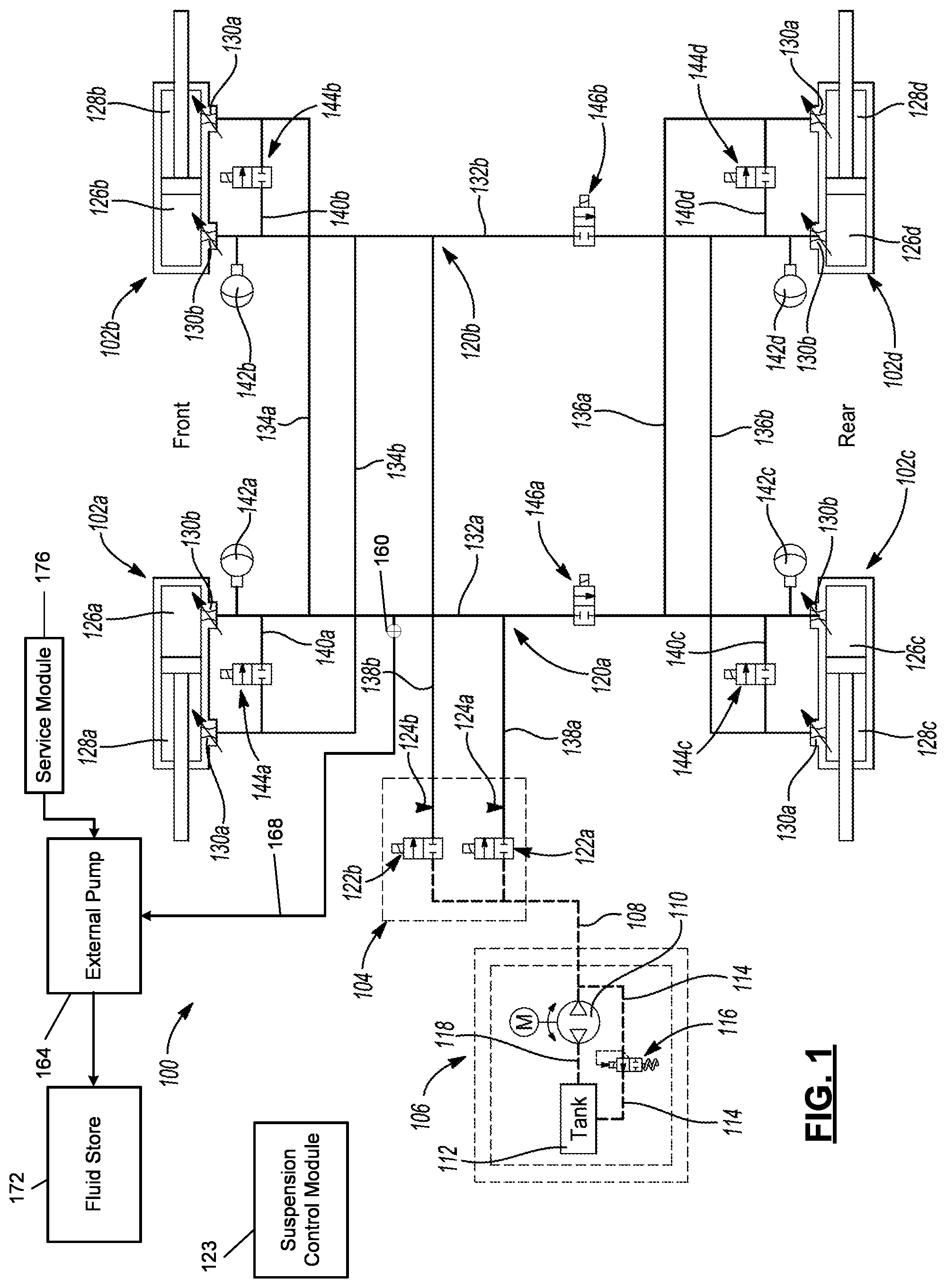
With reference to , a suspension system 100 including a front left damper 102 a , a front right damper 102 b , a back left damper 102 c , and a back right damper 102 d . While it should be appreciated that the suspension system 100 described herein may include a different number of dampers than those shown in the drawings, in most automotive applications, four dampers are used at each corner of a vehicle to control vertical movements of the front and rear wheels of the vehicle. Thus, the front left damper 102 a controls (e.g., dampens) up and down (i.e., vertical) movements of the front left wheel of the vehicle, the front right damper 102 b controls (e.g., dampens) up and down (i.e., vertical) movements of the front right wheel of the vehicle, the back left damper 102 c controls (e.g., dampens) up and down (i.e., vertical) movements of the back left wheel of the vehicle, and the back right damper 102 d controls (e.g., dampens) up and down (i.e., vertical) movements of the back right wheel of the vehicle.
The suspension system 100 also includes a manifold assembly 104 that is connected in fluid communication with a pump assembly 106 by a pump hydraulic line 108 . Although other configurations are possible, in the illustrated example, the pump assembly 106 includes a bi-directional pump 110 , a hydraulic reservoir 112 (e.g., a tank), and a bypass hydraulic line 114 that can be open and closed by a pressure relief valve 116 . The bi-directional pump 110 includes a first inlet/outlet port that is connected to the pump hydraulic line 108 and a second inlet/outlet port that is connected in fluid communication with the hydraulic reservoir 112 by a reservoir hydraulic line 118 . The bi-directional pump 110 may operate (i.e., pump fluid) in two opposite directions depending on the polarity of the electricity that is supplied to the pump 110 , so the first inlet/outlet port may operate as either an inlet port or an outlet port depending on the direction the bi-directional pump 110 is operating in and the same is true for the second inlet/outlet port of the bi-directional pump 110 . In the example where the first inlet/outlet port is operating as an inlet port for the bi-directional pump 110 and the second inlet/outlet port is operating as an outlet port for the bi-directional pump 110 , the bi-directional pump 110 draws in hydraulic fluid from the pump hydraulic line 108 via the first inlet/outlet port and discharges hydraulic fluid into the reservoir hydraulic line 118 via the second inlet/outlet port. As such, the bi-directional pump 110 produces a negative pressure in the pump hydraulic line 108 that can be used by manifold assembly 104 to reduced fluid pressure in the suspension system 100 . In the example where the second inlet/outlet port is operating as an inlet port for the bi-directional pump 110 and the first inlet/outlet port is operating as an outlet port for the bi-directional pump 110 , the bi-directional pump 110 draws in hydraulic fluid from the reservoir hydraulic line 118 via the second inlet/outlet port and discharges hydraulic fluid into the pump hydraulic line 108 via the first inlet/outlet port. As such, the bi-directional pump 110 produces a positive pressure in the pump hydraulic line 108 that can be used by manifold assembly 104 to increase fluid pressure in the suspension system 100 . The bypass hydraulic line 114 runs from the pump hydraulic line 108 to the hydraulic reservoir 112 and bleeds fluid back into the hydraulic reservoir 112 when the pressure in the pump hydraulic line 108 exceeds a threshold pressure that causes the pressure relief valve 116 to open.
The manifold assembly 104 is connected in fluid communication with the front and rear dampers 102 a , 102 b , 102 c , 102 d by first and second hydraulic circuits 120 a , 120 b . The manifold assembly 104 includes first and second manifold valves 122 a , 122 b that are connected in parallel with the pump hydraulic line 108 . The first hydraulic circuit 120 a is connected in fluid communication with the first manifold valve 122 a and the second hydraulic circuit 120 b is connected in fluid communication with the second manifold valve 122 b . The manifold assembly 104 also includes a first pressure sensor 124 a that is arranged to monitor the pressure in the first hydraulic circuit 120 a and a second pressure sensor 124 b that is arranged to monitor the pressure in the second hydraulic circuit 120 b . The bi-directional pump 110 of the pump assembly 106 and first and second pressure sensors 124 a , 124 b and the first and second manifold valves 122 a , 122 b of the manifold assembly 104 are electrically connected to a suspension control module 123 , which is configured to activate (i.e., turn on in forward or reverse) the bi-directional pump 110 and electronically actuate (i.e., open and close) the first and second manifold valves 122 a , 122 b in response to various inputs, including signals from the first and second pressure sensors 124 a , 124 b . When the suspension control module 123 opens the first and second manifold valves 122 a , 122 b , the fluid pressure in the first and second hydraulic circuits 120 a , 120 b increases or decreases, respectively, depending on which direction the bi-directional pump 110 is running in.
The anti-pitch and anti-roll capabilities of the suspension system 100 will be explained in greater detail below. However, from it should be appreciated that fluid pressure in the first and second hydraulic circuits 120 a , 120 b operate to dynamically adjust the roll and pitch stiffness of the vehicle and can be used to either augment or completely replace mechanical stabilizer bars/anti-roll bars. Such mechanical systems require relatively straight, unobstructed runs between each of the front dampers 102 a , 102 b and each of the back dampers 102 c , 102 d . Accordingly, the suspension system 100 disclosed herein offers packaging benefits because the dampers 102 a , 102 b , 102 c , 102 d only need to be hydraulically connected to the manifold assembly 104 and to the suspension control module 123 .
Each of the dampers 102 a , 102 b , 102 c , 102 d of the suspension system 100 includes a damper housing, a piston rod, and a piston that is mounted on the piston rod. The piston is arranged in sliding engagement with the inside of the damper housing such that the piston divides the damper housing into compression and rebound chambers. As such, the front left damper 102 a includes a first compression chamber 126 a and a first rebound chamber 128 a , the front right damper 102 b includes a second compression chamber 126 b and a second rebound chamber 128 b , the back left damper 102 c includes a third compression chamber 126 c and a third rebound chamber 128 c , and the back right damper 102 d includes a fourth compression chamber 126 d and a fourth rebound chamber 128 d.
In each damper 102 a , 102 b , 102 c , 102 d , the piston is a closed piston with no fluid flow paths defined within or by its structure. In addition, there are no other fluid flow paths in the damper housing such that no fluid is communicated between the compression and rebound chambers of the dampers 102 a , 102 b , 102 c , 102 d except through the first and second hydraulic circuits 120 a , 120 b . The rebound chambers 128 a , 128 b , 128 c , 128 d of the dampers 102 a , 102 b , 102 c , 102 d decrease in volume during rebound/extension strokes and increase in volume during compression strokes of the dampers 102 a , 102 b , 102 c , 102 d . The compression chambers 126 a , 126 b , 126 c , 126 d of the dampers 102 a , 102 b , 102 c , 102 d decrease in volume during compression strokes of the dampers 102 a , 102 b , 102 c , 102 d and increase in volume during rebound/extension strokes of the dampers 102 a , 102 b , 102 c , 102 d.
Each damper 102 a , 102 b , 102 c , 102 d also includes rebound and compression chamber ports 130 a , 130 b in the damper housing that are each provided with dampening valves. The rebound chamber port 130 a is arranged in fluid communication with the rebound chamber 128 a , 128 b , 128 c , 128 d of the damper 102 a , 102 b , 102 c , 102 d and the second port 130 b is arranged in fluid communication with the compression chamber 126 a , 126 b , 126 c , 126 d of the damper 102 a , 102 b , 102 c , 102 d . The dampening valves in the rebound and compression chamber ports 130 a , 130 b can be passive/spring-biased valves (e.g., spring-disc stacks) or active valves (e.g., electromechanical valves) and control fluid flow into and out of the compression and rebound chambers of the dampers 102 a , 102 b , 102 c , 102 d to provide one or more rebound dampening rates and compression dampening rates for each of the dampers 102 a , 102 b , 102 c , 102 d.
The first hydraulic circuit 120 a includes a first longitudinal hydraulic line 132 a that extends between and fluidly connects the second port 130 b (to the first compression chamber 126 a ) of the front left damper 102 a and the second port 130 b (to the third compression chamber 126 c ) of the back left damper 102 c . The first hydraulic circuit 120 a includes a front hydraulic line 134 a that extends between and fluidly connects the first longitudinal hydraulic line 132 a and the rebound chamber port 130 a (to the second rebound chamber 128 b ) of the front right damper 102 b . The first hydraulic circuit 120 a also includes a rear hydraulic line 136 a that extends between and fluidly connects the first longitudinal hydraulic line 132 a and the rebound chamber port 130 a (to the fourth rebound chamber 128 d ) of the back right damper 102 d . The first hydraulic circuit 120 a further includes a first manifold hydraulic line 138 a that extends between and fluidly connects the first longitudinal hydraulic line 132 a and the first manifold valve 122 a . The second hydraulic circuit 120 b includes a second longitudinal hydraulic line 132 b that extends between and fluidly connects the compression chamber port 130 b (to the second compression chamber 126 b ) of the front right damper 102 b and the compression chamber port 130 b (to the fourth compression chamber 126 d ) of the back right damper 102 d . The second hydraulic circuit 120 b includes a front hydraulic line 134 b that extends between and fluidly connects the second longitudinal hydraulic line 132 b and the rebound chamber port 130 a (to the first rebound chamber 128 a ) of the front left damper 102 a . The second hydraulic circuit 120 b also includes a rear hydraulic line 136 b that extends between and fluidly connects the second longitudinal hydraulic line 132 b and the rebound chamber port 130 a (to the third rebound chamber 128 c ) of the back left damper 102 c . The second hydraulic circuit 120 b further includes a second manifold hydraulic line 138 b that extends between and fluidly connects the second longitudinal hydraulic line 132 b and the second manifold valve 122 b . It should be appreciated that the word “longitudinal” as used in the first and second longitudinal hydraulic lines 132 a , 132 b simply means that the first and second longitudinal hydraulic lines 132 a , 132 b run between the front dampers 102 a , 102 b and the back dampers 102 c , 102 d generally. The first and second longitudinal hydraulic lines 132 a , 132 b need not be linear or arranged in any particular direction as long as they ultimately connect the front dampers 102 a , 102 b and the back dampers 102 c , 102 d.
The suspension system 100 also includes four bridge hydraulic lines 140 a , 140 b , 140 c , 140 d that fluidly couple the first and second hydraulic circuits 120 a , 120 b and each corner of the vehicle. The four bridge hydraulic lines 140 a , 140 b , 140 c , 140 d include a front left bridge hydraulic line 140 a that extends between and fluidly connects the first longitudinal hydraulic line 132 a of the first hydraulic circuit 120 a and the front hydraulic line 134 b of the second hydraulic circuit 120 b , a front right bridge hydraulic line 140 b that extends between and fluidly connects the front hydraulic line 134 a of the first hydraulic circuit 120 a and the second longitudinal hydraulic line 132 b of the second hydraulic circuit 120 b , a back left bridge hydraulic line 140 c that extends between and fluidly connects the first longitudinal hydraulic line 132 a of the first hydraulic circuit 120 a and the rear hydraulic line 136 b of the second hydraulic circuit 120 b , and a back right bridge hydraulic line 140 d that extends between and fluidly connects the rear hydraulic line 136 a of the first hydraulic circuit 120 a and the second longitudinal hydraulic line 132 b of the second hydraulic circuit 120 b.
The front left bridge hydraulic line 140 a is connected to the first longitudinal hydraulic line 132 a between the compression chamber port 130 b of the front left damper 102 a and the front hydraulic line 134 a of the first hydraulic circuit 120 a . The front right bridge hydraulic line 140 b is connected to the second longitudinal hydraulic line 132 b between the compression chamber port 130 b of the front right damper 102 b and the front hydraulic line 134 b of the second hydraulic circuit 120 b . The back left bridge hydraulic line 140 c is connected to the first longitudinal hydraulic line 132 a between the compression chamber port 130 b of the back left damper 102 c and the rear hydraulic line 136 a of the first hydraulic circuit 120 a . The back right bridge hydraulic line 140 d is connected to the second longitudinal hydraulic line 132 b between the compression chamber port 130 b of the back right damper 102 d and the rear hydraulic line 136 b of the second hydraulic circuit 120 b . In the illustrated example, the various hydraulic lines are made of flexible tubing (e.g., hydraulic hoses), but it should be appreciated that other conduit structures and/or fluid passageways can be used.
A front left accumulator 142 a is arranged in fluid communication with the first longitudinal hydraulic line 132 a at a location between the compression chamber port 130 b of the front left damper 102 a and the front left bridge hydraulic line 140 a . A front right accumulator 142 b is arranged in fluid communication with the second longitudinal hydraulic line 132 b at a location between the compression chamber port 130 b of the front right damper 102 b and the front right bridge hydraulic line 140 b . A back left accumulator 142 c is arranged in fluid communication with the first longitudinal hydraulic line 132 a at a location between the compression chamber port 130 b of the back left damper 102 c and the back left bridge hydraulic line 140 c . A back right accumulator 142 d is arranged in fluid communication with the second longitudinal hydraulic line 132 b at a location between the compression chamber port 130 b of the back right damper 102 d and the back right bridge hydraulic line 140 d . Each of the accumulators 142 a , 142 b , 142 c , 142 d have a variable fluid volume that increases and decreases depending on the fluid pressure in the first and second longitudinal hydraulic lines 132 a , 132 b . It should be appreciated that the accumulators 142 a , 142 b , 142 c , 142 d may be constructed in a number of different ways. For example and without limitation, the accumulators 142 a , 142 b , 142 c , 142 d may have accumulation chambers and pressurized gas chambers that are separated by floating pistons or flexible membranes.
The suspension system 100 also includes six electro-mechanical comfort valves 144 a , 144 b , 144 c , 144 d , 146 a , 146 b that are connected in-line (i.e., in series) with each of the bridge hydraulic lines 140 a , 140 b , 140 c , 140 d and each of the longitudinal hydraulic lines 132 a , 132 b . A front left comfort valve 144 a is positioned in the front left bridge hydraulic line 140 a . A front right comfort valve 144 b is positioned in the front right bridge hydraulic line 140 b . A back left comfort valve 144 c is positioned in the back left bridge hydraulic line 140 c . A back right comfort valve 144 d is positioned in the back right bridge hydraulic line 140 d . A first longitudinal comfort valve 146 a is positioned in the first longitudinal hydraulic line 132 a between the front and rear hydraulic lines 134 a , 136 a of the first hydraulic circuit 120 a . A second longitudinal comfort valve 146 b is positioned in the second longitudinal hydraulic line 132 b between the front and rear hydraulic lines 134 b , 136 b of the second hydraulic circuit 120 b . In the illustrated example, the comfort valves 144 a , 144 b , 144 c , 144 d and the longitudinal comfort valves 146 a , 146 b are semi-active electro-mechanical valves with a combination of passive spring-disk elements and a solenoid. The comfort valves 144 a , 144 b , 144 c , 144 d and the longitudinal comfort valves 146 a , 146 b are electronically connected to the suspension control module 123 , which is configured to supply electrical current to the solenoids of the comfort valves 144 a , 144 b , 144 c , 144 d and the longitudinal comfort valves 146 a , 146 b to selectively and individually open and close the comfort valves 144 a , 144 b , 144 c , 144 d and the longitudinal comfort valves 146 a , 146 b.
The first pressure sensor 124 a of the manifold assembly 104 is arranged to measure fluid pressure in the first manifold hydraulic line 138 a and the second pressure sensor 124 b of the manifold assembly 104 is arranged to measure fluid pressure in the second manifold hydraulic line 138 b . When the vehicle is cornering, braking, or accelerating, the lateral and longitudinal acceleration is measured by one or more accelerometers (not shown) and the anti-roll torque to control the roll and pitch of the vehicle is calculated by the suspension control module 123 . Alternatively, the lateral and longitudinal acceleration of the vehicle can be computed by the suspension control module 123 based on a variety of different inputs, including without limitation, steering angle, vehicle speed, brake pedal position, and/or accelerator pedal position. The dampers 102 a , 102 b , 102 c , 102 d are used to provide forces that counteract the roll moment induced by the lateral and longitudinal acceleration, thus reducing the roll and pitch angles of the vehicle.
When the first and second manifold valves 122 a , 122 b are closed, the first and second hydraulic circuits 120 a , 120 b operate as a closed loop system, either together or separately depending on the open or closed status of the electro-mechanical comfort valves 144 a , 144 b , 144 c , 144 d and the longitudinal comfort valves 146 a , 146 b . When the first and/or second manifold valves 122 a , 122 b are open, the bi-directional pump 110 either adds or removes fluid from the first and/or second hydraulic circuits 120 a , 120 b . As will be explained in greater detail below, the suspension system 100 can control the roll stiffness of the vehicle, which changes the degree to which the vehicle will lean to one side or the other during corning (i.e., roll)
For example, when the vehicle is put into a right-hand turn, the momentum of the sprung weight of the vehicle tends to make the vehicle lean left towards the outside of the turn, compressing the front left damper 102 a and the back left damper 102 c . When this occurs, fluid flows out from the first compression chamber 126 a of the front left damper 102 a and the third compression chamber 126 c of the back left damper 102 c into the first longitudinal hydraulic line 132 a of the first hydraulic circuit 120 a . As a result of the weight transfer to the left side of the vehicle, the front right damper 102 b and back right damper 102 d begin to extend, causing fluid to flow out of the second rebound chamber 128 b of the front right damper 102 b and the fourth rebound chamber 128 d of the back right damper 102 d into the front and rear hydraulic lines 134 a , 136 a of the first hydraulic circuit 120 a . When the comfort valves 144 a , 144 b , 144 c , 144 d are closed, the fluid flow out of the first compression chamber 126 a of the front left damper 102 a , out of the third compression chamber 126 c of the back left damper 102 c , out of the second rebound chamber 128 b of the front right damper 102 b , and out of the fourth rebound chamber 128 d of the back right damper 102 d and into the front and rear hydraulic lines 134 a , 136 a of the first hydraulic circuit 120 a increases the pressure in the front left and back left accumulators 142 a , 142 c , thus providing a passive roll resistance where it becomes increasingly more difficult to compress the front left damper 102 a and the back left damper 102 c since the first compression chamber 126 a of the front left damper 102 a and the third compression chamber 126 c of the back left damper 102 c are connected in fluid communication with the first hydraulic circuit 120 a . At the same time, fluid flows out of front right and back right accumulators 142 b , 142 d and into the first rebound chamber 128 a of the front left damper 102 a , into the third rebound chamber 128 c of the back left damper 102 c , into the second compression chamber 126 b of the front right damper 102 b , and into the fourth compression chamber 126 d of the back right damper 102 d . The resulting pressure difference between the dampers 102 a , 102 b , 102 c , 102 d generates damper forces that counteract or resist the roll moment of the vehicle. Additional roll resistance can be added by opening the first manifold valve 122 a as the bi-directional pump 110 is running in a first direction where the bi-directional pump 110 draws in hydraulic fluid from the reservoir hydraulic line 118 and discharges hydraulic fluid into the pump hydraulic line 108 to produce a positive pressure in the pump hydraulic line 108 , which increases fluid pressure in the first hydraulic circuit 120 a when the first manifold valve 122 a is open.
The opposite is true when the vehicle is put into a left-hand turn, where the momentum of the sprung weight of the vehicle tends to make the vehicle lean right towards the outside of the turn, compressing the front right damper 102 b and the back right damper 102 d . When this occurs, fluid flows out from the second compression chamber 126 b of the front right damper 102 b and the fourth compression chamber 126 d of the back right damper 102 d into the second longitudinal hydraulic line 132 b of the second hydraulic circuit 120 b . As a result of the weight transfer to the right side of the vehicle, the front left damper 102 a and back left damper 102 c begin to extend, causing fluid to flow out of the first rebound chamber 128 a of the front left damper 102 a and the third rebound chamber 128 c of the back left damper 102 c into the front and rear hydraulic lines 134 b , 136 b of the second hydraulic circuit 120 b . When the comfort valves 144 a , 144 b , 144 c , 144 d are closed, the fluid flow out of the second compression chamber 126 b of the front right damper 102 b , out of the fourth compression chamber 126 d of the back right damper 102 d , out of the first rebound chamber 128 a of the front left damper 102 a , and out of the third rebound chamber 128 c of the back left damper 102 c and into the front and rear hydraulic lines 134 b , 136 b of the second hydraulic circuit 120 b increases the pressure in the front right and back right accumulators 142 b , 142 d , thus providing a passive roll resistance where it becomes increasingly more difficult to compress the front right damper 102 b and the back right damper 102 d since the second compression chamber 126 b of the front right damper 102 b and the fourth compression chamber 126 d of the back right damper 102 d are connected in fluid communication with the second hydraulic circuit 120 b . At the same time, fluid flows out of front left and back left accumulators 142 a , 142 c and into the second rebound chamber 128 b of the front right damper 102 b , into the fourth rebound chamber 128 d of the back right damper 102 d , into the first compression chamber 126 a of the front left damper 102 a , and into the third compression chamber 126 c of the back left damper 102 c . The resulting pressure difference between the dampers 102 a , 102 b , 102 c , 102 d generates damper forces that counteract or resist the roll moment of the vehicle. Additional roll resistance can be added by opening the second manifold valve 122 b as the bi-directional pump 110 is running in the first direction where the bi-directional pump 110 draws in hydraulic fluid from the reservoir hydraulic line 118 and discharges hydraulic fluid into the pump hydraulic line 108 to produce a positive pressure in the pump hydraulic line 108 , which increases fluid pressure in the second hydraulic circuit 120 b when the second manifold valve 122 b is open.
It should also be appreciated that during cornering, the roll stiffness of the front dampers 102 a , 102 b can be coupled or de-coupled from the roll stiffness of the rear dampers 102 c , 102 d by opening and closing the first and/or second longitudinal comfort valves 146 a , 146 b . For example, the roll stiffness of the front left damper 102 a and the back left damper 102 c will be coupled when the first longitudinal comfort valve 146 a is open and decoupled when the first longitudinal comfort valve 146 a is closed. Similarly, the roll stiffness of the front right damper 102 b and the back right damper 102 d will be coupled when the second longitudinal comfort valve 146 b is open and decoupled when the second longitudinal comfort valve 146 b is closed.
When roll stiffness is not required, the comfort valves 144 a , 144 b , 144 c , 144 d and the longitudinal comfort valves 146 a , 146 b can be opened to enhance the ride comfort of the suspension system 100 and reduce or eliminate unwanted suspension movements resulting from the hydraulic coupling of one damper of the system to another damper of the system (e.g., where the compression of one damper causes movement and/or a dampening change in another damper). For example, when the front left comfort valve 144 a is open and the front left damper 102 a undergoes a compression stroke as the front left wheel hits a bump, fluid may flow from the first compression chamber 126 a of the front left damper 102 a , into the first longitudinal hydraulic line 132 a , from the first longitudinal hydraulic line 132 a to the front hydraulic line 134 b of the second hydraulic circuit 120 b by passing through the front left bridge hydraulic line 140 a and the front left comfort valve 144 a , and into the first rebound chamber 128 a of the front left damper 102 a . Thus, fluid can travel from the first compression chamber 126 a to the first rebound chamber 128 a of the front left damper 102 a with the only restriction coming from the dampening valves in the rebound and compression chamber ports 130 a , 130 b of the front left damper 102 a . As such, when all of the comfort valves 144 a , 144 b , 144 c , 144 d and the longitudinal comfort valves 146 a , 146 b are open, the dampers 102 a , 102 b , 102 c , 102 d are effectively decoupled from one another for improved ride comfort. It should also be appreciated that to return the suspension system 100 to this “comfort mode” of operation, the first and/or second manifold valves 122 a , 122 b may be opened while the bi-directional pump 110 is running in a second direction where the bi-directional pump 110 draws in hydraulic fluid from the pump hydraulic line 108 and discharges hydraulic fluid into the reservoir hydraulic line 118 to produce a negative pressure in the pump hydraulic line 108 that reduces fluid pressure in the first and/or second hydraulic circuits 120 a , 120 b.
illustrates another suspension system 200 that shares many of the same components as the suspension system 100 illustrated in , but in a front axle lift assembly 248 has been added. Rather than repeat the description set forth above, the following paragraphs describe the structure and function of the components in that are new and/or different from those shown and described in connection with . It should be appreciated that the reference numbers in are “ 100 ” series numbers (e.g., 100 , 102 , 104 , etc.) whereas the components in that are the same or similar to the components of the suspension system 100 shown in share the same base reference numbers, but are listed as “ 200 ” series numbers (e.g., 200 , 202 , 204 , etc.). Thus, the same description for element 100 above applies to element 200 in and so on and so forth.
The front axle lift assembly 248 illustrated in includes a front left lifter 250 a on the front left damper 202 a and a front right lifter 250 b on the front right damper 202 b . Although other configurations are possible, in the illustrated example, the front left damper 202 a and the front right damper 202 b include a front left coil spring 252 a and a front right coil spring 252 b , respectively, that extend co-axially and helically about the piston rods of the front dampers 202 a , 202 b in a coil-over arrangement. The front lifters 250 a , 250 b are positioned between the front coils springs 252 a , 252 b and the first and second rebound chambers 228 a , 228 b of the front dampers 202 a , 202 b and extend co-axially and annularly about the piston rods. The manifold assembly 204 further includes a third manifold valve 222 c that is connected in fluid communication with the pump hydraulic line 208 . A front axle lift hydraulic line 254 a extends between and is fluidly connected to the third manifold valve 222 c with the front left lifter 250 a and the front right lifter 250 b . A third pressure sensor 224 c is arranged to monitor the fluid pressure in the front axle lift hydraulic line 254 a . Each front lifter 250 a , 250 b is axially expandable such that an increase in fluid pressure inside the front lifters 250 a , 250 b causes the front lifters 250 a , 250 b to urge the front coil springs 252 a , 252 b away from the first and second rebound chambers 228 a , 228 b of the front dampers 202 a , 202 b , which operates to lift (i.e., raise) the front of the vehicle, increasing the ride height. To activate the front axle lift assembly 248 , the suspension control module 123 opens the third manifold valve 222 c when the bi-directional pump 210 is running in the first direction where the bi-directional pump 210 draws in hydraulic fluid from the reservoir hydraulic line 218 and discharges hydraulic fluid into the pump hydraulic line 208 to produce a positive pressure in the pump hydraulic line 208 , which increases fluid pressure in the front axle lift hydraulic line 254 a and thus the front lifters 250 a , 250 b . Once a desired lift position is achieved, the controller closes the third manifold valve 222 c . It should therefore be appreciated that the front axle lift assembly 248 can be used to provide improved ground clearance during off-road operation or to give low riding vehicles improved ground clearance when traversing speed bumps. To deactivate the front axle lift assembly 248 , the suspension control module 123 opens the third manifold valve 222 c when the bi-directional pump 210 is running in the second direction where the bi-directional pump 210 draws in hydraulic fluid from the pump hydraulic line 208 and discharges hydraulic fluid into the reservoir hydraulic line 218 to produce a negative pressure in the pump hydraulic line 208 that reduces fluid pressure in the front axle lift hydraulic line 254 a to lower the front of the vehicle back down to an unlifted position.
illustrates another suspension system 300 that shares many of the same components as the suspension systems 100 , 200 illustrated in , but in a rear axle lift assembly 356 has been added. Rather than repeat the description set forth above, the following paragraphs describe the structure and function of the components in that are new and/or different from those shown and described in connection with . It should be appreciated that the reference numbers in are “ 100 ” series numbers (e.g., 100 , 102 , 104 , etc.) and the reference numbers in are “ 200 ” series numbers (e.g., 200 , 202 , 204 , etc.) whereas the components in that are the same or similar to the components of the suspension systems 100 , 200 shown in share the same base reference numbers, but are listed as “ 300 ” series numbers (e.g., 300 , 302 , 304 , etc.). Thus, the same description for elements 100 and 200 above applies to element 300 in and so on and so forth.
The rear axle lift assembly 356 illustrated in includes a back left lifter 350 c on the back left damper 302 c and a back right lifter 350 d on the back right damper 302 d . Although other configurations are possible, in the illustrated example, the back left damper 302 c and the back right damper 302 d include a back left coil spring 352 c and a back right coil spring 352 d , respectively, that extend co-axially and helically about the piston rods of the back dampers 302 c , 302 d in a coil-over arrangement. The back lifters 350 c , 350 d are positioned between the back coils springs 352 c , 352 d and the third and fourth rebound chambers 328 c , 328 d of the back dampers 302 a , 302 b and extend co-axially and annularly about the piston rods. The manifold assembly 304 further includes a fourth manifold valve 322 d that is connected in fluid communication with the pump hydraulic line 308 . A rear axle lift hydraulic line 354 b extends between and is fluidly connected to the fourth manifold valve 322 d with the back left lifter 350 c and the back right lifter 350 d . A fourth pressure sensor 324 d is arranged to monitor the fluid pressure in the rear axle lift hydraulic line 354 b . Each back lifter 350 c , 350 d is axially expandable such that an increase in fluid pressure inside the back lifters 350 c , 350 d causes the back lifters 350 c , 350 d to urge the back coil springs 352 c , 352 d away from the third and fourth rebound chambers 328 c , 328 d of the back dampers 302 c , 302 d , which operates to lift (i.e., raise) the back/rear of the vehicle, increasing the ride height. To activate the rear axle lift assembly 356 , the suspension control module 123 opens the fourth manifold valve 322 d when the bi-directional pump 310 is running in the first direction where the bi-directional pump 310 draws in hydraulic fluid from the reservoir hydraulic line 318 and discharges hydraulic fluid into the pump hydraulic line 308 to produce a positive pressure in the pump hydraulic line 308 , which increases fluid pressure in the rear axle lift hydraulic line 354 b and thus the back lifters 350 c , 350 d . Once a desired lift position is achieved, the suspension control module 123 closes the fourth manifold valve 322 d . It should therefore be appreciated that the rear axle lift assembly 356 can be used in combination with the front axle lift assembly 348 (also described above in connection with ) to provide improved ground clearance during off-road operation or to give low riding vehicles improved ground clearance when traversing speed bumps. To deactivate the rear axle lift assembly 356 , the suspension control module 123 opens the fourth manifold valve 322 d when the bi-directional pump 310 is running in the second direction where the bi-directional pump 310 draws in hydraulic fluid from the pump hydraulic line 308 and discharges hydraulic fluid into the reservoir hydraulic line 318 to produce a negative pressure in the pump hydraulic line 308 that reduces fluid pressure in the rear axle lift hydraulic line 354 b to lower the rear of the vehicle back down to an unlifted position.
With reference to , another suspension system 400 is illustrated that shares many of the same components as the suspension system 100 illustrated in . Rather than repeat the description set forth above, the following paragraphs describe the structure and function of the components in that are new and/or different from those shown and described in connection with . It should be appreciated that the reference numbers in are “ 100 ” series numbers (e.g., 100 , 102 , 104 , etc.) whereas the components in that are the same or similar to the components of the suspension system 100 shown in share the same base reference numbers, but are listed as “ 400 ” series numbers (e.g., 400 , 402 , 404 , etc.). Thus, the same description for element 100 above applies to element 400 in and so on and so forth.
The suspension system 400 in also includes a front left damper 402 a , a front right damper 402 b , a back left damper 402 c , and a back right damper 402 d . The suspension system 400 also includes a manifold assembly 404 that is connected in fluid communication with a pump assembly 406 by a pump hydraulic line 408 . Like in , the pump assembly 406 includes a bi-directional pump 410 , a hydraulic reservoir 412 (e.g., a tank), and a bypass hydraulic line 414 that can be open and closed by a pressure relief valve 416 .
The manifold assembly 404 is connected in fluid communication with the front and rear dampers 402 a , 402 b , 402 c , 402 d by four hydraulic circuits 420 a , 420 b , 420 c , 420 d : a first hydraulic circuit 420 a , a second hydraulic circuit 420 b , a third hydraulic circuit 420 c , and a fourth hydraulic circuit 420 d . The manifold assembly 404 includes four manifold valves 422 a , 422 b , 422 c , 422 d (a first manifold valve 422 a , a second manifold valve 422 b , a third manifold valve 422 c , and a fourth manifold valve 422 d ) that are connected in parallel with the pump hydraulic line 408 . The manifold assembly 404 further includes a first manifold comfort valve 460 a , a second manifold comfort valve 460 b , and six manifold conduits 462 a , 462 b , 462 c , 462 d , 462 e , 462 f : a first manifold conduit 462 a , a second manifold conduit 462 b , a third manifold conduit 462 c , a fourth manifold conduit 462 d , a fifth manifold conduit 462 e , and a sixth manifold conduit 462 f . The first manifold conduit 462 a is connected in fluid communication with the first manifold valve 422 a and the first manifold comfort valve 460 a while the second manifold conduit 462 b is connected in fluid communication with the second manifold valve 422 b and the second manifold comfort valve 460 b . The third manifold conduit 462 c is connected in fluid communication with the third manifold valve 422 c and the fourth manifold conduit 462 d is connected in fluid communication with the fourth manifold valve 422 d . The fifth manifold conduit 462 e is connected in fluid communication with the first manifold comfort valve 460 a and the sixth manifold conduit 462 f is connected in fluid communication with the second manifold comfort valve 460 b . Additional structure and operational details of the manifold assembly 404 is described below in connection with ; however, it should be appreciated from that fluid pressure in the four hydraulic circuits 420 a , 420 b , 420 c , 420 d operates to dynamically adjust the roll and pitch stiffness of the vehicle and can be used to either augment or completely replace mechanical stabilizer bars/anti-roll bars. Such mechanical systems require relatively straight, unobstructed runs between each of the front dampers 402 a , 402 b and each of the back dampers 402 c , 402 d . Accordingly, the suspension system 400 disclosed herein offers packaging benefits because the dampers 402 a , 402 b , 402 c , 402 d only need to be hydraulically connected to the manifold assembly 404 .
The first hydraulic circuit 420 a includes a first cross-over hydraulic line 464 a that extends between and fluidly connects the compression chamber port 430 b (to the first compression chamber 426 a ) of the front left damper 402 a and the rebound chamber port 430 a (to the fourth rebound chamber 428 d ) of the back right damper 402 d . The first hydraulic circuit 420 a also includes a first manifold hydraulic line 438 a that extends between and fluidly connects the first cross-over hydraulic line 464 a and the first manifold conduit 462 a . The second hydraulic circuit 420 b includes a second cross-over hydraulic line 464 b that extends between and fluidly connects the compression chamber port 430 b (to the second compression chamber 426 b ) of the front right damper 402 b and the rebound chamber port 430 a (to the third rebound chamber 428 c ) of the back left damper 402 c . The second hydraulic circuit 420 b also includes a second manifold hydraulic line 438 b that extends between and fluidly connects the second cross-over hydraulic line 464 b and the second manifold conduit 462 b . The third hydraulic circuit 420 c includes a third cross-over hydraulic line 464 c that extends between and fluidly connects the rebound chamber port 430 a (to the first rebound chamber 428 a ) of the front left damper 402 a and the compression chamber port 430 b (to the fourth compression chamber 426 d ) of the back right damper 402 d . The third hydraulic circuit 420 c also includes a third manifold hydraulic line 438 c that extends between and fluidly connects the third cross-over hydraulic line 464 c and the sixth manifold conduit 462 f . The fourth hydraulic circuit 420 d includes a fourth cross-over hydraulic line 464 d that extends between and fluidly connects the rebound chamber port 430 a (to the second rebound chamber 428 b ) of the front right damper 402 b and the compression chamber port 430 b (to the third compression chamber 426 c ) of the back left damper 402 c . The fourth hydraulic circuit 420 d also includes a fourth manifold hydraulic line 438 d that extends between and fluidly connects the fourth cross-over hydraulic line 464 d and the fifth manifold conduit 462 e . It should be appreciated that the word “cross-over” as used in the first, second, third, and fourth cross-over hydraulic lines 464 a , 464 b , 464 c , 464 d simply means that the first, second, third, and fourth cross-over hydraulic lines 464 a , 464 b , 464 c , 464 d run between dampers 402 a , 402 b , 402 c , 402 d at opposite corners of the vehicle (e.g., front left to back right and front right to back left). The first, second, third, and fourth cross-over hydraulic lines 464 a , 464 b , 464 c , 464 d need not be linear or arranged in any particular direction as long as they ultimately connect dampers 402 a , 402 b , 402 c , 402 d positioned at opposite corners of the vehicle.
The suspension system 400 also includes four bridge hydraulic lines 440 a , 440 b , 440 c , 440 d that fluidly couple the first and third hydraulic circuits 420 a , 420 c and the second and fourth hydraulic circuits 420 b , 420 d to one another. The four bridge hydraulic lines 440 a , 440 b , 440 c , 440 d include a front left bridge hydraulic line 440 a that extends between and fluidly connects the first cross-over hydraulic line 464 a and the third cross-over hydraulic line 464 c , a front right bridge hydraulic line 440 b that extends between and fluidly connects the second cross-over hydraulic line 464 b and the fourth cross-over hydraulic line 464 d , a back left bridge hydraulic line 440 c that extends between and fluidly connects the second cross-over hydraulic line 464 b and the fourth cross-over hydraulic line 464 d , and a back right bridge hydraulic line 440 d that extends between and fluidly connects the first cross-over hydraulic line 464 a and the third cross-over hydraulic line 464 c.
The front left bridge hydraulic line 440 a is connected to the first cross-over hydraulic line 464 a between the compression chamber port 430 b of the front left damper 402 a and the first manifold hydraulic line 438 a and is connected to the third cross-over hydraulic line 464 c between the rebound chamber port 430 a of the front left damper 402 a and the third manifold hydraulic line 438 c . The front right bridge hydraulic line 440 b is connected to the second cross-over hydraulic line 464 b between the compression chamber port 430 b of the front right damper 402 b and the second manifold hydraulic line 438 b and is connected to the fourth cross-over hydraulic line 464 d between the rebound chamber port 430 a of the front right damper 402 b and the fourth manifold hydraulic line 438 d . The back left bridge hydraulic line 440 c is connected to the second cross-over hydraulic line 464 b between the rebound chamber port 430 a of the back left damper 402 c and the second manifold hydraulic line 438 b and is connected to the fourth cross-over hydraulic line 464 d between the compression chamber port 430 b of the back left damper 402 c and the fourth manifold hydraulic line 438 d . The back right bridge hydraulic line 440 d is connected to the first cross-over hydraulic line 464 a between the rebound chamber port 430 a of the back right damper 402 d and the first manifold hydraulic line 438 a and is connected to the third cross-over hydraulic line 464 c between the compression chamber port 430 b of the back right damper 402 d and the third manifold hydraulic line 438 c . In the illustrated example, the various hydraulic lines are made of flexible tubing (e.g., hydraulic hoses), but it should be appreciated that other conduit structures and/or fluid passageways can be used.
A front left accumulator 442 a is arranged in fluid communication with the first cross-over hydraulic line 464 a at a location between the compression chamber port 430 b of the front left damper 402 a and the front left bridge hydraulic line 440 a . A front right accumulator 442 b is arranged in fluid communication with the second cross-over hydraulic line 464 b at a location between the compression chamber port 430 b of the front right damper 402 b and the front right bridge hydraulic line 440 b . A back left accumulator 442 c is arranged in fluid communication with the fourth cross-over hydraulic line 464 d at a location between the compression chamber port 430 b of the back left damper 402 c and the back left bridge hydraulic circuit 420 c . A back right accumulator 442 d is arranged in fluid communication with the third cross-over hydraulic line 464 c at a location between the compression chamber port 430 b of the back right damper 402 d and the back right bridge hydraulic line 440 d . Each of the accumulators 442 a , 442 b , 442 c , 442 d have a variable fluid volume that increases and decreases depending on the fluid pressure in the first and second longitudinal hydraulic lines 432 a , 432 b . It should be appreciated that the accumulators 442 a , 442 b , 442 c , 442 d may be constructed in a number of different ways. For example and without limitation, the accumulators 442 a , 442 b , 442 c , 442 d may have accumulation chambers and pressurized gas chambers that are separated by floating pistons or flexible membranes.
The suspension system 400 also includes four electro-mechanical comfort valves 444 a , 444 b , 444 c , 444 d that are connected in-line (i.e., in series) with each of the bridge hydraulic lines 440 a , 440 b , 440 c , 440 d . A front left comfort valve 444 a is positioned in the front left bridge hydraulic line 440 a . A front right comfort valve 444 b is positioned in the front right bridge hydraulic line 440 b . A back left comfort valve 444 c is positioned in the back left bridge hydraulic line 440 c . A back right comfort valve 444 d is positioned in the back right bridge hydraulic line 440 d . In the illustrated example, the four comfort valves 444 a , 444 b , 444 c , 444 d and the two manifold comfort valves 460 a , 460 b are semi-active electro-mechanical valves with a combination of passive spring-disk elements and a solenoid. The comfort valves 444 a , 444 b , 444 c , 444 d and the two manifold comfort valves 460 a , 460 b are electronically connected to the suspension control module 123 , which is configured to supply electrical current to the solenoids of the comfort valves 444 a , 444 b , 444 c , 444 d and the two manifold comfort valves 460 a , 460 b to selectively and individually open and close the comfort valves 444 a , 444 b , 444 c , 444 d and the two manifold comfort valves 460 a , 460 b.
When the manifold valves 422 a , 422 b , 422 c , 422 d are closed, the hydraulic circuits 420 a , 420 b , 420 c , 420 d operate as a closed loop system, either together or separately depending on the open or closed status of the comfort valves 444 a , 444 b , 444 c , 444 d and manifold comfort valves 460 a , 460 b . When the manifold valves 422 a , 422 b , 422 c , 422 d are open, the bi-directional pump 110 either adds or removes fluid from one or more of the hydraulic circuits 420 a , 420 b , 420 c , 420 d . There are three primary types of suspension movements that the illustrated suspension system 400 can control either passively (i.e., as a closed loop system) or actively (i.e., as an open loop system) by changing or adapting the roll and/or pitch stiffness of the vehicle: leaning to one side or the other during cornering (i.e., roll) pitching forward during braking (i.e., brake dive), and pitching aft during acceleration (i.e., rear end squat). Descriptions of how the suspension system 400 reacts to each of these conditions are provided below.
When the vehicle is put into a right-hand turn, the momentum of the sprung weight of the vehicle tends to make the vehicle lean left towards the outside of the turn, compressing the front left damper 402 a and the back left damper 402 c . When this occurs, fluid flows out from the first compression chamber 426 a of the front left damper 402 a and the third compression chamber 426 c of the back left damper 402 c into the first and fourth cross-over hydraulic lines 464 a , 464 d . As a result of the weight transfer to the left side of the vehicle, the front right damper 402 b and back right damper 402 d begin to extend, causing fluid to flow out of the second rebound chamber 428 b of the front right damper 402 b and the fourth rebound chamber 428 d of the back right damper 402 d into the first and fourth cross-over hydraulic lines 464 a , 464 d . When the comfort valves 444 a , 444 b , 444 c , 444 d are closed, the fluid flow out of the first compression chamber 426 a of the front left damper 402 a , out of the third compression chamber 426 c of the back left damper 402 c , out of the second rebound chamber 428 b of the front right damper 402 b and out of the fourth rebound chamber 428 d of the back right damper 402 d and into the first and fourth cross-over hydraulic lines 464 a , 464 d increases the pressure in the front left and back left accumulators 442 a , 442 c , thus providing a passive roll resistance where it becomes increasingly more difficult to compress the front left damper 402 a and the back left damper 402 c since the first compression chamber 426 a of the front left damper 402 a and the third compression chamber 426 c of the back left damper 402 c are connected in fluid communication with the first and fourth hydraulic circuits 420 a , 420 d . At the same time, fluid flows out of front left and back left accumulators 442 b , 442 d and into the first rebound chamber 428 a of the front left damper 402 a , into the third rebound chamber 428 c of the back left damper 402 c , into the second compression chamber 426 b of the front right damper 402 b , and into the fourth compression chamber 426 d of the back right damper 402 d . The resulting pressure difference between the dampers 402 a , 402 b , 402 c , 402 d generates damper forces that counteract or resist the roll moment of the vehicle. Additional roll resistance can be added by opening the first manifold valve 422 a and the first manifold comfort valve 460 a as the bi-directional pump 410 is running in a first direction where the bi-directional pump 410 draws in hydraulic fluid from the reservoir hydraulic line 418 and discharges hydraulic fluid into the pump hydraulic line 408 to produce a positive pressure in the pump hydraulic line 408 , which increases fluid pressure in the first and fourth hydraulic circuits 420 a , 420 d.
The opposite is true when the vehicle is put into a left-hand turn, where the momentum of the sprung weight of the vehicle tends to make the vehicle lean right towards the outside of the turn, compressing the front right damper 402 b and the back right damper 402 d . When this occurs, fluid flows out from the second compression chamber 426 b of the front right damper 402 b and the fourth compression chamber 426 d of the back right damper 402 d into the second and third cross-over hydraulic lines 464 b , 464 c . As a result of the weight transfer to the right side of the vehicle, the front left damper 402 a and back left damper 402 c begin to extend, causing fluid to flow out of the first rebound chamber 428 a of the front left damper 402 a and the third rebound chamber 428 c of the back left damper 402 c into the second and third cross-over hydraulic lines 464 b , 464 c . When the comfort valves 444 a , 444 b , 444 c , 444 d are closed, the fluid flow out of the second compression chamber 426 b of the front right damper 402 b , out of the fourth compression chamber 426 d of the back right damper 402 d , out of the first rebound chamber 428 a of the front left damper 402 a , and out of the third rebound chamber 428 c of the back left damper 402 c and into the second and third cross-over hydraulic lines 464 b , 464 c increases the pressure in the front right and back right accumulators 142 b , 142 d , thus providing a passive roll resistance where it becomes increasingly more difficult to compress the front right damper 402 b and the back right damper 402 d since the second compression chamber 426 b of the front right damper 402 b and the fourth compression chamber 426 d of the back right damper 402 d are connected in fluid communication with the second and third hydraulic circuits 420 b , 420 c . At the same time, fluid flows out of front right and back right accumulators 442 a , 442 c and into the second rebound chamber 428 b of the front right damper 402 b , into the fourth rebound chamber 428 d of the back right damper 402 d , into the first compression chamber 426 a of the front left damper 402 a , and into the third compression chamber 426 c of the back left damper 402 c . The resulting pressure difference between the dampers 402 a , 402 b , 402 c , 402 d generates damper forces that counteract or resist the roll moment of the vehicle. Additional roll resistance can be added by opening the second manifold valve 422 b and the second manifold comfort valve 460 b as the bi-directional pump 410 is running in the first direction where the bi-directional pump 410 draws in hydraulic fluid from the reservoir hydraulic line 418 and discharges hydraulic fluid into the pump hydraulic line 408 to produce a positive pressure in the pump hydraulic line 408 , which increases fluid pressure in the second and third hydraulic circuits 420 b , 420 c.
During braking, the momentum of the sprung weight of the vehicle tends to make the vehicle pitch or dive forward, compressing the front left damper 402 a and the front right damper 402 b . When this occurs, fluid flows out from the first compression chamber 426 a of the front left damper 402 a into the first cross-over hydraulic line 464 a and out from the second compression chamber 426 b of the front right damper 402 b into the second cross-over hydraulic line 464 b . As a result of the weight transfer to the front of the vehicle, the back left damper 402 c and back right damper 402 d begin to extend, causing fluid to flow out of the third rebound chamber 428 c of the back left damper 402 c into the second cross-over hydraulic line 464 b and out of the fourth rebound chamber 428 d of the back right damper 402 d into the first cross-over hydraulic line 464 a . With the front left, front right, back left, and back right comfort valves 444 a , 444 b , 444 c , 444 d and the first and second manifold comfort valves 460 a , 460 b all closed, the fluid flow out of the third rebound chamber 428 c of the back left damper 402 c and the fourth rebound chamber 428 d of the back right damper 402 d into the first and second cross-over hydraulic lines 464 a , 464 b increases the pressure in the front left and front right accumulators 442 a , 442 b , thus providing a passive pitch resistance where it becomes increasingly more difficult to compress the front left damper 402 a and the front right damper 402 b since the first compression chamber 426 a of the front left damper 402 a and the second compression chamber 426 b of the front right damper 402 b are connected in fluid communication with the first and second hydraulic circuits 420 a , 420 b.
During acceleration, the momentum of the sprung weight of the vehicle tends to make the vehicle pitch or squat rearward (i.e., aft), compressing the back left damper 402 c and the back right damper 402 d . When this occurs, fluid flows out from the third compression chamber 426 c of the back left damper 402 c into the fourth cross-over hydraulic line 464 d and out of the fourth compression chamber 426 d of the back right damper 402 d into the third cross-over hydraulic line 464 c . As a result of the weight transfer to the back/rear of the vehicle, the front left damper 402 a and front right damper 402 b begin to extend, causing fluid to flow out of the first rebound chamber 428 a of the front left damper 402 a into the third cross-over hydraulic line 464 c and out of the second rebound chamber 428 b of the front right damper 402 b into the fourth cross-over hydraulic line 464 d . With the front left, front right, back left, and back right comfort valves 444 a , 444 b , 444 c , 444 d and the first and second manifold comfort valves 460 a , 460 b all closed, the fluid flow out of the first rebound chamber 428 a of the front left damper 402 a and the second rebound chamber 428 b of the front right damper 402 b into the third and fourth cross-over hydraulic lines 464 c , 464 d increases the pressure in the back left and back right accumulators 442 c , 442 d , thus providing a passive pitch resistance where it becomes increasingly more difficult to compress the back left damper 402 c and the back right damper 402 d since the third compression chamber 426 c of the back left damper 402 c and the fourth compression chamber 426 d of the back right damper 402 d are connected in fluid communication with the third and fourth hydraulic circuits 420 c , 420 d.
When active or passive roll and/or pitch stiffness is not required, the four comfort valves 444 a , 444 b , 444 c , 444 d and the two manifold comfort valves 460 a , 460 b can be opened to enhance the ride comfort of the suspension system 400 and reduce or eliminate unwanted suspension movements resulting from the hydraulic coupling of one damper of the system to another damper of the system (e.g., where the compression of one damper causes movement and/or a dampening change in another damper). For example, when the front left comfort valve 444 a is open and the front left damper 402 a undergoes a compression stroke as the front wheel hits a bump, fluid may flow from the first compression chamber 426 a of the front left damper 402 a , into the first cross-over hydraulic line 464 a , from the first cross-over hydraulic line 464 a to the third cross-over hydraulic line 464 c by passing through the front left bridge hydraulic line 440 a and the front left comfort valve 444 a , and into the first rebound chamber 428 a of the front left damper 402 a . Thus, fluid can travel from the first compression chamber 426 a to the first rebound chamber 428 a of the front left damper 402 a with the only restriction coming from the dampening valves in the rebound and compression chamber ports 430 a , 430 b of the front left damper 402 a . As such, when all of the comfort valves 444 a , 444 b , 444 c , 444 d and the manifold comfort valves 460 a , 460 b are open, the dampers 402 a , 402 b , 402 c , 402 d are effectively decoupled from one another for improved ride comfort. It should also be appreciated that to return the suspension system 400 to this “comfort mode” of operation, the manifold valves 422 a , 422 b , 422 c , 422 d and/or the manifold comfort valves 460 a , 460 b may be opened while the bi-directional pump 410 is running in a second direction where the bi-directional pump 410 draws in hydraulic fluid from the pump hydraulic line 408 and discharges hydraulic fluid into the reservoir hydraulic line 418 to produce a negative pressure in the pump hydraulic line 408 that reduces fluid pressure in the hydraulic circuits 420 a , 420 b , 420 c , 420 d of the suspension system 400 .
illustrates the manifold assembly 404 of the suspension system 400 in more detail. The manifold assembly 404 includes first and second piston bores 466 a , 466 b that slidingly receive first and second floating pistons 468 a , 468 b , respectively. Each floating piston 468 a , 468 b includes a piston rod 458 and first and second piston heads 470 a , 470 b that are fixably coupled to opposing ends of the piston rod 458 . A chamber divider 472 is fixably mounted at a midpoint of each of the first and second piston bores 466 a , 466 b . Each chamber divider 472 includes a through-bore that slidingly receives the piston rod 458 . As such, the first piston bore 466 a is divided by the first floating piston 468 a into a first piston chamber 474 a that is arranged in fluid communication with the first manifold conduit 462 a , a second piston chamber 474 b disposed between the first piston head 470 a of the first floating piston 468 a and the chamber divider 472 in the first piston bore 466 a , a third piston chamber 474 c disposed between the second piston head 470 b of the first floating piston 468 a and the chamber divider 472 in the first piston bore 466 a , and a fourth piston chamber 474 d that is arranged in fluid communication with the fifth manifold conduit 462 e . Similarly, the second piston bore 466 b is divided by the second floating piston 468 b into a fifth piston chamber 474 e that is arranged in fluid communication with the second manifold conduit 462 b , a sixth piston chamber 474 f disposed between the first piston head 470 a of the second floating piston 468 b and the chamber divider 472 in the second piston bore 466 b , a seventh piston chamber 474 g disposed between the second piston head 470 b of the second floating piston 468 b and the chamber divider 472 in the second piston bore 466 b , and an eighth piston chamber 474 h that is arranged in fluid communication with the sixth manifold conduit 462 f . Optionally, biasing members (e.g., springs) (not shown) may be placed in the second, third, sixth, and seventh piston chambers 474 b , 474 c , 474 f , 474 g to naturally bias the first and second floating pistons 468 a , 468 b to a centered position where the second and third piston chambers 474 b , 474 c and the sixth and seventh piston chambers 474 f , 474 g have equal volumes.
The first manifold conduit 462 a is arranged in fluid communication with the first manifold hydraulic line 438 a , the second manifold conduit 462 b is arranged in fluid communication with the second manifold hydraulic line 438 b , the fifth manifold conduit 462 e is arranged in fluid communication with the fourth manifold hydraulic line 438 d , and the sixth manifold conduit 462 f is arranged in fluid communication with the third manifold hydraulic line 438 c . The third manifold conduit 462 c is arranged in fluid communication with the second and sixth piston chambers 474 b , 474 f while the fourth manifold conduit 462 d is arranged in fluid communication with the third and seventh piston chambers 474 c , 474 g . As a result, fluid pressure in the fourth piston chamber 474 d and thus the fifth manifold conduit 462 e can be increased independently of the first manifold conduit 462 a by closing the first manifold comfort valve 460 a and opening the fourth manifold valve 422 d when the bi-directional pump 410 is running in the first direction, which increases pressure in the third piston chamber 474 c and urges the first floating piston 468 a to the right in , decreasing the volume of the fourth piston chamber 474 d and increasing the pressure in the fourth piston chamber 474 d . Similarly, fluid pressure in the eighth piston chamber 474 h and thus the sixth manifold conduit 462 f can be increased independently of the second manifold conduit 462 b by closing the second manifold comfort valve 460 b and opening the fourth manifold valve 422 d when the bi-directional pump 410 is running in the first direction, which increases pressure in the seventh piston chamber 474 g and urges the second floating piston 468 b to the right in , decreasing the volume of the eighth piston chamber 474 h and increasing the pressure in the eighth piston chamber 474 h.
Fluid pressure in the first piston chamber 474 a and thus the first manifold conduit 462 a can also be increased without opening the first manifold valve 422 a by actuating the first floating piston 468 a , where the first manifold comfort valve 460 a is closed and the third manifold valve 422 c is open when the bi-directional pump 410 is running in the first direction, which increases pressure in the second piston chamber 474 b and urges the first floating piston 468 a to the left in , decreasing the volume of the first piston chamber 474 a and increasing the pressure in the first piston chamber 474 a . Similarly, fluid pressure in the fifth piston chamber 474 e and the second manifold conduit 462 b can also be increased without opening the second manifold valve 422 b by actuating the second floating piston 468 b , where the second manifold comfort valve 460 b is closed and the third manifold valve 422 c is open when the bi-directional pump 410 is running in the first direction, which increases pressure in the sixth piston chamber 474 f and urges the second floating piston 468 b to the left in , decreasing the volume of the fifth piston chamber 474 e and increasing the pressure in the second piston chamber 474 e.
The manifold assembly 404 may further include a first manifold accumulator 476 a that is arranged in fluid communication with the third manifold conduit 462 c between the third manifold valve 422 c and the second and sixth piston chambers 474 b , 474 f and a second manifold accumulator 476 b that is arranged in fluid communication with the fourth manifold conduit 462 d between the third and seventh piston chambers 474 c , 474 g . The first and second manifold accumulators 476 a , 476 b may be constructed in a number of different ways. For example and without limitation, the first and second manifold accumulators 476 a , 476 b may have accumulation chambers and pressurized gas chambers that are separated by floating pistons or flexible membranes. Under braking, fluid flow within the four hydraulic circuits generates a pressure difference between the first and second manifold accumulators 476 a , 476 b , which in turn causes an increase in pressure in the front left and front right accumulators 442 a , 442 b and provides a pitch stiffness that resists the compression of the front dampers 402 a , 402 b and rebound/extension of the back dampers 402 c , 402 d . Under acceleration, fluid flow within the four hydraulic circuits generates an opposite pressure difference between the first and second manifold accumulators 476 a , 476 b , which in turn causes an increase in pressure in the back left and back right accumulators 442 c , 442 d and provides a pitch stiffness that resists the rebound/extension of the front dampers 402 a , 402 b and compression of the back dampers 402 c , 402 d . Additional pitch resistance can be added before a braking or acceleration event by opening the third and fourth manifold valves 422 c , 422 d as the bi-directional pump 410 is running in the first direction. The bi-directional pump 410 draws in hydraulic fluid from the reservoir hydraulic line 418 and discharges hydraulic fluid into the pump hydraulic line 408 to produce a positive pressure in the pump hydraulic line 408 , which increases fluid pressure in the first and second manifold accumulators 476 a , 476 b . In a similar way, the pitch stiffness of the system can be reduced before a braking or acceleration event by running the bi-directional pump 410 in the second direction while the third and fourth manifold valves 422 c , 422 d.
The manifold assembly 404 may also include six pressure sensors 424 a , 424 b , 424 c , 424 d , 424 e , 424 f : a first pressure sensor 424 a arranged to monitor fluid pressure in the first manifold conduit 462 a , a second pressure sensor 424 b arranged to monitor fluid pressure in the second manifold conduit 462 b , a third pressure sensor 424 c arranged to monitor fluid pressure in the third manifold conduit 462 c , a fourth pressure sensor 424 d arranged to monitor fluid pressure in the fourth manifold conduit 462 d , a fifth pressure sensor 424 e arranged to monitor fluid pressure in the fifth manifold conduit 462 e , and a sixth pressure sensor 424 f arranged to monitor fluid pressure in the sixth manifold conduit 462 f . While not shown in , the pressure sensors 424 a , 424 b , 424 c , 424 d , 424 e , 424 f are all electrically connected to the suspension control module 123 .
illustrates another suspension system 600 that shares many of the same components as the suspension system 400 illustrated in , but in different pump 610 and manifold assemblies 604 have been utilized. Rather than repeat the description set forth above, the following paragraphs describe the structure and function of the components in that are new and/or different from those shown and described in connection with . It should be appreciated that the reference numbers in are “ 400 ” series numbers (e.g., 400 , 402 , 404 , etc.) whereas the components in that are the same or similar to the components of the suspension system 400 shown in share the same base reference numbers, but are listed as “ 600 ” series numbers (e.g., 600 , 602 , 604 , etc.). Thus, the same description for element 400 above applies to element 600 in and so on and so forth.
The pump assembly 606 illustrated in includes a single direction pump 610 with an inlet port that is connected in fluid communication with the hydraulic reservoir 612 by a reservoir hydraulic line 618 and an outlet port that is connected to the pump hydraulic line 608 . In operation, the single direction pump 610 draws in hydraulic fluid from the reservoir hydraulic line 618 via the inlet port and discharges hydraulic fluid into the pump hydraulic line 608 via the outlet port. As such, the single direction pump 610 produces a positive pressure in the pump hydraulic line 608 that can be used by manifold assembly 604 to increase fluid pressure in the suspension system 600 . A check valve 678 is positioned in the pump hydraulic line 608 to prevent back feed when the single direction pump 610 is turned off. The pump assembly 606 also includes a return hydraulic line 680 that extends from the pump hydraulic line 108 to the hydraulic reservoir 612 . A first pump valve 682 a is positioned in-line with the return hydraulic line 680 . The pump assembly 606 also includes a pump bridge hydraulic line 683 that includes a second pump valve 682 b mounted in-line with the pump bridge hydraulic line 683 . The pump bridge hydraulic line 683 connects to the pump hydraulic line 608 at a location between the single direct pump 610 and the check valve 678 and connects to the return hydraulic line 680 at a location between the first pump valve 682 a and the hydraulic reservoir 612 . In accordance with this arrangement, fluid pressure in the pump hydraulic line 608 can be increased by turning on the pump 610 and closing the second pump valve 682 b and fluid pressure in the pump hydraulic line 608 can be decreased by turning the pump 610 off and opening the first pump valve 682 a.
In the example illustrated in , only three manifold valves 622 a , 622 b , 622 c (i.e., the first manifold valve 622 a , the second manifold valve 622 b , and the third manifold valve 622 c ) are connected in parallel with the pump hydraulic line 608 . The fourth manifold valve 622 d is positioned between the first and second piston bores 666 a , 666 b and is arranged in fluid communication with the third manifold conduit 662 c on one side and the fourth manifold conduit 662 d on the other side. Thus, to increase fluid pressure in the fifth and/or sixth manifold conduits 662 e , 662 f independently of the first and second manifold conduits 662 a , 662 b , the third and fourth manifold valves 622 c , 622 d must be open while the pump 610 is running and the first and second manifold comfort valves 660 a , 660 b are closed to increase fluid pressure in the third and seventh piston chambers 674 c , 674 g , which urges the first and second floating pistons 668 a , 668 b to the right in decreasing the volume of the fourth and eighth piston chambers 674 d , 674 h and increasing the pressure in the fourth and eighth piston chambers 674 d , 674 h.
illustrates another suspension system 700 that shares many of the same components as the suspension system 400 illustrated in , but in a different manifold assembly 704 has been utilized. Rather than repeat the description set forth above, the following paragraphs describe the structure and function of the components in that are new and/or different from those shown and described in connection with . It should be appreciated that the reference numbers in are “ 400 ” series numbers (e.g., 400 , 402 , 404 , etc.) whereas the components in that are the same or similar to the components of the suspension system 400 shown in share the same base reference numbers, but are listed as “ 700 ” series numbers (e.g., 700 , 702 , 704 , etc.). Thus, the same description for element 400 above applies to element 700 in and so on and so forth.
The manifold assembly 704 illustrated in has the same components and hydraulic arrangement as the manifold assembly 404 illustrated in , but in the placement of the various components of the manifold assembly 704 is different to allow the manifold assembly 704 to be packaged in the front of the vehicle between the front dampers 702 a , 702 b . The manifold assembly 704 illustrated in includes a front left sub-assembly 784 a and a front right sub-assembly 784 b . The front right sub-assembly 784 b includes the first piston bore 766 a , the first floating piston 768 a , the first manifold valve 722 a , the third manifold valve 722 c , the first manifold conduit 762 a , and the fifth manifold conduit 762 e . The front left sub-assembly 784 a includes the second piston bore 466 b , the second floating piston 768 b , the second manifold valve 722 b , the fourth manifold valve 722 d , the second manifold conduit 762 b , and the sixth manifold conduit 762 f . The pump hydraulic line 708 extends between the front left and front right sub-assemblies 784 a , 784 b and splits to connect to the manifold valves 722 a , 722 b , 722 c , 722 d on either side. The third and fourth manifold conduits 762 c , 762 d extend laterally between the front left and front right sub-assemblies 784 a , 784 b to connect the second and sixth piston chambers 774 b , 774 f and the third and seventh piston chambers 774 c , 774 g , respectively. It should be appreciated that the order and arrangement of the piston chambers 774 e , 774 f , 774 g , 774 h in the second piston bore 766 b shown in is opposite from that shown in . In other words, in accordance with the arrangement shown in , the first piston chamber 774 a (which is connected in fluid communication with the first manifold conduit 762 a ) faces the fifth piston chamber 774 e (which is connection in fluid communication with the second manifold conduit 762 b ). In other words, in the fifth piston chamber 774 e (which is connection in fluid communication with the second manifold conduit 762 b ) is to the right of the eighth piston chamber 774 h (which is connected in fluid communication with the sixth manifold conduit 762 f ), whereas in the fifth piston chamber 474 e (which is connected in fluid communication with the second manifold conduit 462 b ) is to the left of the eighth piston chamber 474 h (which is connected in fluid communication with the sixth manifold conduit 462 f ). This reversal of the arrangement of the piston chambers 774 e , 774 f , 774 g , 774 h in the second piston bore 766 b simplifies and shortens the runs required for the manifold hydraulic lines 738 a , 738 b , 738 c , 738 d and is therefore advantageous.
includes a functional block diagram of an example implementation of the suspension control module 123 . A pump control module 804 receives power from a battery 808 of the vehicle. The pump control module 804 controls operation, speed, and direction of operation of a pump 812 of the suspension system. More specifically, the pump control module 804 controls application of power to the pump 812 of the suspension system. Examples of the pump 812 are discussed above. For example, in the examples of , the pump control module 804 controls application of power to the pump 110 , 210 , 310 , or 410 . In the examples of , the pump control module 804 controls application of power to the pump 610 or 710 . The pump control module 804 may control, for example, a polarity of power applied to the pump 812 , a frequency of power applied to the pump 812 , a magnitude of voltage applied to the pump 812 , and/or a current through the pump 812 .
A valve control module 816 controls actuation (e.g., opening and closing) of valves 820 of the suspension system. Examples of the valves 820 are discussed above with respect to examples of . For example, the valve control module 816 controls actuation of the valves 122 a , 122 b , 144 a - c , and 146 a - b in the example of .
Referring back to , the tank 112 may be not accessible to add hydraulic fluid into the suspension system or to remove hydraulic fluid from the system. The tank 112 may not include a port, opening, inlet, nozzle, etc. through which hydraulic fluid can be externally input to the tank 112 or externally removed from the tank 112 .
As such, the suspension system may include a quick connect valve 160 . The quick connect valve 160 may be fluidly connected, for example, to the line 132 a or in another suitable location. While the quick connect valve 160 is shown in the example of , the quick connect valve 160 can be included in all of the suspension systems above and the following is also applicable to all of the example embodiments shown and described. In various implementations, two or more quick connect valves may be included.
An external pump 164 can be connected to the quick connect valve 160 via a hydraulic line 168 . When on and connected via the quick connect valve 160 , the external pump 164 may pump hydraulic fluid from a (hydraulic) fluid store 172 into the suspension system.
A service module 176 may control operation of the external pump 164 . The service module 176 may, for example, connect to an on board diagnostic (OBD) port of the vehicle. Via the OBD port, the service module 176 may coordinate control of various components with the suspension control module 123 , receive one or more operating parameters (e.g., pressures measured by the pressure sensors discussed above), and perform one or more other functions.
Referring back to , a communication module 824 may communicate with the service module 176 using a communication protocol, such as a car area network (CAN) bus communication protocol or another suitable communication protocol.
A rinsing module 828 may control operation of the pump 812 and actuation of the valves 820 to rinse the pump 812 with hydraulic fluid from the tank 112 . In various implementations, the rinsing may be accomplished without the external pump 164 . In various implementations, the rinsing module 828 may coordinate control of the pump 812 and actuation of the valves 820 with the service module 176 and operation of the external pump 164 to rinse the pump 812 . Rinsing is performed using monitoring current of the electric motor of the pump 812 . A current sensor 840 measures current (motor current) through the electric motor of the pump 812 .
The rinsing module 828 operates pump 812 in the first direction (via the pump control module 804 ) and opens all of the valves 820 of the suspension system (via the valve control module 816 ) to rinse the pump using hydraulic fluid from the tank 112 . Hydraulic fluid is pumped out of the suspension system and the tank 112 via the quick connect port 160 and a hydraulic line (e.g., 168 ) connected to the quick connect port 160 . In various implementations, while the pump 812 is being operated, the external pump 164 may also be operated to draw hydraulic fluid out of the suspension system and the tank 112 .
The current should stay relatively constant while the pump 812 is operating in the first direction and is pumping hydraulic fluid out of the tank 112 . The rinsing module 828 may determine that rinsing is complete when a decrease in the current is more negative than a predetermined negative value. The decrease in current may indicate that the pump 812 is no longer pumping hydraulic fluid from the tank 112 .
is a functional block diagram of an example implementation of the rinsing module 828 . A command module 904 generates commands for operation of the pump 812 and actuation of the valves 820 for rinsing. The pump control module 804 controls the pump 812 according to the pump command, and the valve control module 816 actuates the valves 820 according to the valve command. In this manner, the rinsing module 828 controls the pump 812 and the valves 820 for rinsing.
The command module 904 may start the rinsing in response to receipt of a start signal, such as from the service module 176 . The service module 176 may generate the start signal, for example, in response to receipt of user input indicative of a request to rinse the pump 812 to the service module 176 .
When the start signal is received, the command module 904 may first verify that hydraulic fluid is present in the tank 112 . For example, the command module 904 may operate the pump 812 in the first direction (toward the suspension system) and close all of the valves 820 . Because the hydraulic fluid cannot enter the suspension system, the pressure in the hydraulic line connected to the output of the pump 812 should increase. The current through the motor of the pump 812 should therefore also increase. With the valves 820 closed, no pressure increases may be measured by a pressure sensor, so motor current may be used. The command module 904 may determine that hydraulic fluid is present in the tank 112 , for example, when the current through the motor is greater than a predetermined current (e.g., 2 amps or more) within a predetermined period (e.g., 2 seconds) of starting the pump 812 with the valves 820 closed. The command module 904 may determine that the tank 112 is empty and not perform the rinsing when the current does not become greater than the predetermined current within the predetermined period.
When hydraulic fluid is in the tank 112 , the command module 904 may open all of the valves 820 and operate the pump 812 in the first direction (toward the suspension system). This pumps hydraulic fluid from the tank 112 through the pump 812 and out of the suspension system via the quick connect port 160 .
A comparison module 908 determines and indicates whether rinsing is complete based on the motor current. The comparison module 908 may set a rinsing signal to a first state when rinsing is not yet complete and hydraulic fluid is still present in the tank 112 , and set the rinsing signal to a second state when the rinsing is complete and the pump 812 is no longer pumping hydraulic fluid from the tank 112 .
Regarding the motor current, a filter module 912 may filter the motor current measured by the motor current sensor 840 , such as using a low pass filter (LPF) or another suitable type of filter. The motor current sensor 840 generates motor current samples at a predetermined frequency, such as 60 Hertz or another suitable frequency. In other words, the motor current sensor 840 generates the motor current every predetermined period ( 1 /predetermined frequency). The filter module 912 outputs filtered motor currents at the predetermined frequency. The filter module 912 may be implemented to prevent large changes in the motor current. In various implementations, the filter module 912 may be omitted.
A buffer module 916 , such as a one unit delay buffer module (z −1 ) receives the output of the filter module 912 . While the filter module 912 is outputting the present filtered motor current (at time t), the buffer module 916 outputs the last filtered motor current from the predetermined period earlier (time t- 1 ). In other words, the buffer module 916 outputs the last filtered motor current generated by the filter module 912 immediately before the filter module 912 output the (present) filtered motor current. The buffer module 916 may include a ring buffer, a first-in first-out (FIFO) buffer, a shift register, or another suitable type of buffer.
A difference module 920 determines a difference between the filtered motor current from the filter module 912 and the previous filtered motor current output by the buffer module 916 . For example, the difference module 920 may set the difference based on or equal to the filtered motor current minus the previous filtered motor current. In this manner, the difference being negative indicates that the motor current decreased over time.
An amplifier module 924 amplifies the difference. For example, the amplifier module 924 may multiply the difference by a predetermined gain value that is greater than 1.0. The predetermined gain value may be calibrated and may be, for example, approximately 5.0 or another suitable value.
A filter module 928 filters the amplified difference using a filter, such as a LPF or another suitable type of filter. The filter module 928 may be implemented to prevent large changes in the amplified difference. In various implementations, the filter module 928 may be omitted.
The comparison module 908 may generate the rinsing signal based on a comparison of the filtered difference output by the filter module 928 with a predetermined negative value. For example, the comparison module 908 may set the rinsing signal to the first state when the filtered difference is greater than (positive or less negative than) the predetermined negative value. The comparison module 908 may set the rinsing signal to the second state when the filtered difference is less than (i.e., more negative than) or equal to the predetermined negative value. The predetermined negative value is calibrated and is less than 0.0 (i.e., negative). For example only, the predetermined negative value may be, for example, −100 milliamps (ma) or another suitable value.
When the rinsing is complete (e.g., when the rinsing signal is in the second state), the command module 904 stops the pump 812 (e.g., disconnects the pump 812 from power) and closes the valves 820 . The suspension system can later be refilled with hydraulic fluid when desired.
is a flowchart depicting an example method of rinsing the pump 812 . A hydraulic line (e.g., the hydraulic line 168 ) is connected to the quick connect port 160 as to be able to pump hydraulic fluid out of the suspension system by operating the pump 812 . As discussed above, the rinsing may be performed with or without the external pump 164 .
Control begins with 1004 where the command module 904 determines whether to start rinsing the pump 812 with hydraulic fluid from the tank 112 . For example, the command module 904 may determine whether the start signal has been received. If 1004 is true, control may continue with 1012 . If 1004 is false, control may remain at 1004 .
At 1012 , the command module 904 opens the valves 820 and operates the pump 812 in the first direction to pump hydraulic fluid out of the tank 112 and through the pump 812 . The buffer module 916 may also initialize the previous filtered motor current at 1012 , such as by setting the previous filtered motor current to 0 Amps or to the present filtered motor current. The service module 176 may also operate the external pump 164 to draw hydraulic fluid out of the system at 1012 .
In various implementations, the command module 904 may, before opening the valves 820 and turning on the external pump 164 , close the valves 820 and operate the pump 812 to determine whether the suspension system is already empty. For example, the command module 904 may determine the that the suspension system is already empty when the filtered motor current is less than a predetermined positive current for a predetermined period. The predetermined positive current is greater than 0 amps and may be calibrated. The command module 904 may continue with 1012 if the suspension system is not already empty.
At 1016 , the filter module 912 receives a motor current measurement from the current sensor 840 . At 1020 , the filter module 912 applies the filter to the motor current to produce the filtered motor current. At 1024 , the difference module 920 determines the difference between the filtered motor current and the previous filtered motor current (e.g., difference=filtered motor current−previous filtered motor current).
At 1028 , the amplifier module 924 may amplify the difference, such as by multiplying the difference by the predetermined gain value. At 1032 , the filter module 928 may apply the filter to the motor current to produce the filtered difference.
At 1036 , the comparison module 908 compares the filtered difference with the predetermined negative value and determines whether the filtered difference is more negative than the predetermined negative value. If 1036 is true, control continues with 1040 . If 1036 is false, control may transfer to 1044 . At 1040 , the command module 904 turns off the pump 812 and closes all of the valves 820 . At 1044 , the buffer module 916 sets the previous filtered motor current to the present filtered motor current, and control returns to 1016 to continue operating the pump in the first direction with the valves 820 open to continue the rinsing.
The foregoing description is merely illustrative in nature and is in no way intended to limit the disclosure, its application, or uses. The broad teachings of the disclosure can be implemented in a variety of forms. Therefore, while this disclosure includes particular examples, the true scope of the disclosure should not be so limited since other modifications will become apparent upon a study of the drawings, the specification, and the following claims. It should be understood that one or more steps within a method may be executed in different order (or concurrently) without altering the principles of the present disclosure. Further, although each of the embodiments is described above as having certain features, any one or more of those features described with respect to any embodiment of the disclosure can be implemented in and/or combined with features of any of the other embodiments, even if that combination is not explicitly described. In other words, the described embodiments are not mutually exclusive, and permutations of one or more embodiments with one another remain within the scope of this disclosure.
Spatial and functional relationships between elements (for example, between modules, circuit elements, semiconductor layers, etc.) are described using various terms, including “connected,” “engaged,” “coupled,” “adjacent,” “next to,” “on top of,” “above,” “below,” and “disposed.” Unless explicitly described as being “direct,” when a relationship between first and second elements is described in the above disclosure, that relationship can be a direct relationship where no other intervening elements are present between the first and second elements, but can also be an indirect relationship where one or more intervening elements are present (either spatially or functionally) between the first and second elements. As used herein, the phrase at least one of A, B, and C should be construed to mean a logical (A OR B OR C), using a non-exclusive logical OR, and should not be construed to mean “at least one of A, at least one of B, and at least one of C.”
In the figures, the direction of an arrow, as indicated by the arrowhead, generally demonstrates the flow of information (such as data or instructions) that is of interest to the illustration. For example, when element A and element B exchange a variety of information but information transmitted from element A to element B is relevant to the illustration, the arrow may point from element A to element B. This unidirectional arrow does not imply that no other information is transmitted from element B to element A. Further, for information sent from element A to element B, element B may send requests for, or receipt acknowledgements of, the information to element A.
In this application, including the definitions below, the term “module” or the term “controller” may be replaced with the term “circuit.” The term “module” may refer to, be part of, or include: an Application Specific Integrated Circuit (ASIC); a digital, analog, or mixed analog/digital discrete circuit; a digital, analog, or mixed analog/digital integrated circuit; a combinational logic circuit; a field programmable gate array (FPGA); a processor circuit (shared, dedicated, or group) that executes code; a memory circuit (shared, dedicated, or group) that stores code executed by the processor circuit; other suitable hardware components that provide the described functionality; or a combination of some or all of the above, such as in a system-on-chip.
The module may include one or more interface circuits. In some examples, the interface circuits may include wired or wireless interfaces that are connected to a local area network (LAN), the Internet, a wide area network (WAN), or combinations thereof. The functionality of any given module of the present disclosure may be distributed among multiple modules that are connected via interface circuits. For example, multiple modules may allow load balancing. In a further example, a server (also known as remote, or cloud) module may accomplish some functionality on behalf of a client module.
The term code, as used above, may include software, firmware, and/or microcode, and may refer to programs, routines, functions, classes, data structures, and/or objects. The term shared processor circuit encompasses a single processor circuit that executes some or all code from multiple modules. The term group processor circuit encompasses a processor circuit that, in combination with additional processor circuits, executes some or all code from one or more modules. References to multiple processor circuits encompass multiple processor circuits on discrete dies, multiple processor circuits on a single die, multiple cores of a single processor circuit, multiple threads of a single processor circuit, or a combination of the above. The term shared memory circuit encompasses a single memory circuit that stores some or all code from multiple modules. The term group memory circuit encompasses a memory circuit that, in combination with additional memories, stores some or all code from one or more modules.
The term memory circuit is a subset of the term computer-readable medium. The term computer-readable medium, as used herein, does not encompass transitory electrical or electromagnetic signals propagating through a medium (such as on a carrier wave); the term computer-readable medium may therefore be considered tangible and non-transitory. Non-limiting examples of a non-transitory, tangible computer-readable medium are nonvolatile memory circuits (such as a flash memory circuit, an erasable programmable read-only memory circuit, or a mask read-only memory circuit), volatile memory circuits (such as a static random access memory circuit or a dynamic random access memory circuit), magnetic storage media (such as an analog or digital magnetic tape or a hard disk drive), and optical storage media (such as a CD, a DVD, or a Blu-ray Disc).
The apparatuses and methods described in this application may be partially or fully implemented by a special purpose computer created by configuring a general purpose computer to execute one or more particular functions embodied in computer programs. The functional blocks, flowchart components, and other elements described above serve as software specifications, which can be translated into the computer programs by the routine work of a skilled technician or programmer.
The computer programs include processor-executable instructions that are stored on at least one non-transitory, tangible computer-readable medium. The computer programs may also include or rely on stored data. The computer programs may encompass a basic input/output system (BIOS) that interacts with hardware of the special purpose computer, device drivers that interact with particular devices of the special purpose computer, one or more operating systems, user applications, background services, background applications, etc.
The computer programs may include: (i) descriptive text to be parsed, such as HTML (hypertext markup language), XML (extensible markup language), or JSON (JavaScript Object Notation) (ii) assembly code, (iii) object code generated from source code by a compiler, (iv) source code for execution by an interpreter, (v) source code for compilation and execution by a just-in-time compiler, etc. As examples only, source code may be written using syntax from languages including C, C++, C#, Objective-C, Swift, Haskell, Go, SQL, R, Lisp, Java®, Fortran, Perl, Pascal, Curl, OCaml, Javascript®, HTML5 (Hypertext Markup Language 5th revision), Ada, ASP (Active Server Pages), PHP (PHP: Hypertext Preprocessor), Scala, Eiffel, Smalltalk, Erlang, Ruby, Flash®, Visual Basic®, Lua, MATLAB, SIMULINK, and Python®.
Although the terms first, second, third, etc. may be used herein to describe various elements, components, regions, layers and/or sections, these elements, components, regions, layers and/or sections should not be limited by these terms. These terms may be only used to distinguish one element, component, region, layer or section from another region, layer or section. Terms such as “first,” “second,” and other numerical terms when used herein do not imply a sequence or order unless clearly indicated by the context. Thus, a first element, component, region, layer or section discussed below could be termed a second element, component, region, layer or section without departing from the teachings of the example embodiments.
Figures (10)
Citations
This patent cites (205)
- US3334913
- US3635460
- US4076275
- US4270771
- US4349077
- US4390188
- US4537411
- US4625993
- US4830394
- US4848790
- US4911468
- US4911470
- US4973079
- US4999777
- US5033770
- US5037128
- US5056812
- US5074624
- US5085458
- US5085459
- US5097419
- US5100167
- US5119297
- US5145206
- US5160161
- US5162995
- US5174598
- US5188390
- US5193845
- US5199854
- US5251929
- US5322319
- US5515277
- US5529324
- US5556115
- US5562305
- US5601307
- US5619413
- US5630623
- US5631632
- US5735540
- US5769400
- US6010139
- US6015155
- US6202010
- US6259982
- US6266590
- US6282470
- US6374193
- US6470248
- US6502837
- US6519517
- US6556908
- US6669216
- US6761371
- US6859713
- US6880332
- US7040631
- US7311314
- US7311316
- US7350793
- US7384054
- US7472914
- US7686309
- US7789398
- US7862052
- US8075002
- US8123235
- US8459619
- US8672337
- US8695768
- US9080631
- US9150282
- US9428022
- US9597940
- US9829014
- US10350958
- US10421330
- US10752075
- US11220152
- US11390129
- US11529836
- US11618294
- US11685220
- US20010006285
- US20030182990
- US20040061292
- US20040113377
- US20050269753
- US20060151969
- US20060186728
- US20070000478
- US20070278752
- US20080224428
- US20080238004
- US20080269987
- US20080272561
- US20090140501
- US20110025001
- US20120098172
- US20130103259
- US20130300073
- US20140195114
- US20140232082
- US20140265170
- US20140288776
- US20150102921
- US20150224845
- US20170240017
- US20170291465
- US20170305226
- US20180194188
- US20180297422
- US20180304697
- US20180312017
- US20180345747
- US20180356798
- US20190178695
- US20190211897
- US20190344634
- US20190389271
- US20200062068
- US20200094645
- US20200103926
- US20200122539
- US20200223274
- US20200247208
- US20200324607
- US20210101434
- US20210138866
- US20210178845
- US20210178850
- US20210276566
- US20210283969
- US20210316716
- US20210331545
- US20210347221
- US20210402841
- US20220016949
- US20220105770
- US20220105771
- US20220111695
- US20220126642
- US20220144035
- US20220234412
- US20220281280
- US20220314728
- US20220332306
- US20220380004
- US20220396111
- US20220396112
- US20230111977
- US20230113819
- US20230114717
- US20230141764
- US7393300
- US7762000
- US5806301
- US757592
- US2003291836
- US2004215923
- US2005266861
- US2008261186
- US103807344
- US204037280
- US204037282
- US102862456
- US207059676
- US207902078
- US106739915
- US110329235
- US214057159
- US114537072
- US2844413
- US60317928
- US102008024871
- US102009053758
- US102009056105
- US102018206462
- US102020001633
- US102019218699
- US0419865
- US1189774
- US1518721
- US1853442
- US1970229
- US1989072
- US3643544
- US2175848
- US2344323
- US2005 059613
- US2005145137
- US2018016141
- US20140005557
- USWO-9633879
- USWO-2001017807
- USWO-2006/010226
- USWO-2007098559
- USWO-2009055841
- USWO-2009111826
- USWO-2014/152095
- USWO-2015055313
- USWO-2016072510
- USWO-2020185968
- USWO-2020214666