Assembly Jig and Assembly Method Using the Same
Abstract
An assembly jig is suitable for assembling a band button. The band button includes a button body, a compression spring, a torsion spring, a compression spring pin and a torsion spring pin. The assembly jig includes a base, an upper cover, a first pressing component and a pressing mechanism. The base has an accommodating groove, and the accommodating groove is configured for accommodating the button body, the compression spring, the torsion-spring positioning pin and the compression-spring positioning pin. The upper cover is combined with the base and has a slot for accommodating the torsion spring. The first pressing component is configured to press the torsion spring into the button body which is accommodated in the accommodating groove. The pressing mechanism is configured for pressing the compression spring, the compression spring pin and the torsion spring pin into the button body which is accommodated in the accommodating groove.
Claims (16)
1. An assembly jig, suitable for assembling a band button of a watch strap, wherein the band button comprises a button body, a compression spring, a torsion spring, a compression-spring positioning pin and a torsion-spring positioning pin, and the assembly jig comprises: a base having an accommodating groove configured for accommodating the button body, the compression spring, the compression-spring positioning pin and the torsion-spring positioning pin; an upper cover combined with the base and having a slot for accommodating the torsion spring; a first pressing component configured for pressing the torsion spring into the button body which is accommodated in the accommodating groove; and a pressing mechanism configured for pressing the compression spring, the compression-spring positioning pin and the torsion-spring positioning pin into the button body which is accommodated in the accommodating groove.
11. An assembly method for assembling a band button by using an assembly jig, wherein the assembly jig comprises a base, an upper cover, a first pressing component and a pressing mechanism, and the assembly method comprises: disposing a button body, a compression spring, a compression-spring positioning pin and a torsion-spring positioning pin in an accommodating groove of the base; combining the base with the upper cover; disposing a torsion spring in a slot of the upper cover; pressing, by the first pressing component, the torsion spring into the button body which is accommodated in the accommodating groove; and pressing, by the pressing mechanism, the compression spring, the compression-spring positioning pin and the torsion-spring positioning pin into the button body which is accommodated in the accommodating groove.
Show 14 dependent claims
2. The assembly jig according to claim 1 , wherein the upper cover has a channel connecting the slot and the accommodating groove, and the first pressing component is configured for pressing the torsion spring into the button body through the channel.
3. The assembly jig according to claim 1 , wherein the accommodating groove comprises a first sub-accommodating groove, a second sub-accommodating groove and a third sub-accommodating groove, and the first sub-accommodating groove is configured for accommodating the button body, the second sub-accommodating groove is configured for accommodating the compression spring and the compression-spring positioning pin, and the third sub-accommodating groove is configured for accommodating the torsion-spring positioning pin.
4. The assembly jig according to claim 3 , wherein the first sub-accommodating groove, the second sub-accommodating groove and the third sub-accommodating groove extend along a moving direction, and the first sub-accommodating groove is located between the second sub-accommodating groove and the third sub-accommodating groove.
5. The assembly jig according to claim 4 , wherein the upper cover has a channel connecting the slot and the accommodating groove, the channel extends along an extending direction, and the extending direction and the moving direction are perpendicular to each other.
6. The assembly jig according to claim 1 , wherein the slot has an upper opening and a lower opening opposite to the upper opening, and the lower opening is smaller than the upper opening.
7. The assembly jig according to claim 6 , wherein the torsion spring comprises a spiral portion, a first end and a second end opposite to the first end, the spiral portion is disposed between the first end and the second end, the slot has a first wall and a second wall opposite to the first wall, the first wall and the second wall are configured for supporting the first end and the second end respectively.
8. The assembly jig according to claim 1 , wherein the pressing mechanism comprises: a first sliding seat; a second sliding seat; a second pressing component disposed on the first sliding seat, wherein an end of the second pressing component faces the compression-spring positioning pin so as to press the compression spring and the compression-spring positioning pin into the band button; and a third pressing member disposed on the second sliding seat, wherein an end of the third pressing component faces the torsion-spring positioning pin, so as to press the torsion-spring positioning pin into the button body; wherein the assembly jig further comprises a first driving mechanism configured for driving the first sliding seat and the second sliding seat.
9. The assembly jig described in claim 8 , further comprising: a first elastic component connecting the base and the first sliding seat for providing the first sliding seat with a first elastic restoring force to restore the second pressing component; and a second elastic component connecting the base and the second sliding seat for providing the second sliding seat with a second elastic restoring force to restore the third pressing member.
10. The assembly jig according to claim 1 , wherein the assembly jig further comprises a second driving mechanism configured for driving the first pressing component to press the torsion spring into the button body.
12. The assembly method according to claim 11 , wherein the upper cover has a channel connecting the slot and the accommodating groove, and pressing the torsion spring into the button body which is accommodated in the accommodating groove further comprises: pressing, by the first pressing component, the torsion spring into the button body through the channel.
13. The assembly method of claim 11 , wherein the accommodating groove comprises a first sub-accommodating groove, a second sub-accommodating groove and a third sub-accommodating groove, and disposing the button body, the compression spring, the compression-spring positioning pin and the torsion-spring positioning pin in the accommodating groove of the base further comprises: disposing the button body in the first sub-accommodating groove; disposing the compression spring and the compression-spring positioning pin in the second sub-accommodating groove; and disposing the torsion-spring positioning pin in the third sub-accommodating groove.
14. The assembly method according to claim 11 , wherein the assembly jig further comprises a first driving mechanism comprising a first sliding seat, a second sliding seat, a second pressing component and a third pressing component, the second pressing component is disposed on the first sliding seat, and the third pressing component is disposed on the second sliding seat; disposing the button body, the compression spring, the compression-spring positioning pin and the torsion-spring positioning pin in the accommodating groove of the base further comprises: driving, by the first driving mechanism, the first sliding seat to move the second pressing component to press the compression spring and the compression-spring positioning pin into the band button which is accommodated in the accommodating groove; and driving, by the first driving mechanism, the second sliding seat to move the third pressing component to press the torsion-spring positioning pin into the button body which is accommodated in the accommodating groove.
15. The assembly method according to claim 14 , wherein the assembly jig further comprises a first elastic component and a second elastic component, the first elastic component connects the base and the first sliding seat, the second elastic component connects the base and the second sliding seat; in driving the first sliding seat to move the second pressing component, the first elastic component deforms and stores a first elastic potential energy; in driving the second sliding seat to move the third pressing component, the second elastic component deforms and stores a second elastic potential energy; the assembly method further comprises: releasing, by the first elastic component, the first elastic potential energy to provide the first sliding seat with a first elastic restoring force to restore the second pressing component; and releasing, by the second elastic component, the second elastic potential energy to provide the second sliding seat with a second elastic restoring force to restore the third pressing component.
16. The assembly method according to claim 11 , wherein the assembly jig further comprises a second driving mechanism, and the assembly method comprises: driving, by the second driving mechanism, the first pressing component to press the torsion spring into the button body which is accommodated in the accommodating groove.
Full Description
Show full text →
This application claims the benefit of Taiwan application Serial No. 111106805, filed Feb. 24, 2022, the subject matter of which is incorporated herein by reference.
FIELD OF THE INVENTION
The invention relates to an assembly jig and an assembly method using the same.
BACKGROUND OF THE INVENTION
All the band button of the conventional watch straps is assembled manually. As the size of the product becomes smaller and smaller (some springs have an outer diameter of less than 1 mm and a length of only 2 to 4 mm), some problems such as increased assembly difficulty, lower yield, higher labor costs and lower production capacity are occurred. In view of this, how to propose a new band button assembly technology to resolve the abovementioned conventional problems is one of the directions of the efforts of those skilled in the art.
SUMMARY OF THE INVENTION
In an embodiment of the invention, an assembly jig is provided. The assembly jig is suitable for assembling a band button of a watch strap, wherein the band button comprises a button body, a compression spring, a torsion spring, a compression-spring positioning pin and a torsion-spring positioning pin, and the assembly jig includes a base, an upper cover, a first pressing component and a pressing mechanism. The base has an accommodating groove configured for accommodating the button body, the compression spring, the compression-spring positioning pin and the torsion-spring positioning pin; an upper cover combined with the base and having a slot for accommodating the torsion spring. The first pressing component is configured for pressing the torsion spring into the button body which is accommodated in the accommodating groove. The pressing mechanism is configured for pressing the compression spring, the compression-spring positioning pin and the torsion-spring positioning pin into the button body which is accommodated in the accommodating groove.
In another embodiment of the invention, an assembly method is provided. The assembly method for assembling a band button by using an assembly jig, wherein the assembly jig comprises a base, an upper cover, a first pressing component and a pressing mechanism. The assembly method includes the following steps: disposing a button body, a compression spring, a compression-spring positioning pin and a torsion-spring positioning pin in an accommodating groove of the base; combining the base with the upper cover; disposing a torsion spring in a slot of the upper cover; pressing, by the first pressing component, the torsion spring into the button body which is accommodated in the accommodating groove; and pressing, by the pressing mechanism, the compression spring, the compression-spring positioning pin and the torsion-spring positioning pin into the button body which is accommodated in the accommodating groove.
Numerous objects, features and advantages of the invention will be readily apparent upon a reading of the following detailed description of embodiments of the invention when taken in conjunction with the accompanying drawings. However, the drawings employed herein are for the purpose of descriptions and should not be regarded as limiting.
BRIEF DESCRIPTION OF THE DRAWINGS
The above objects and advantages of the invention will become more readily apparent to those ordinarily skilled in the art after reviewing the following detailed description and accompanying drawings, in which:
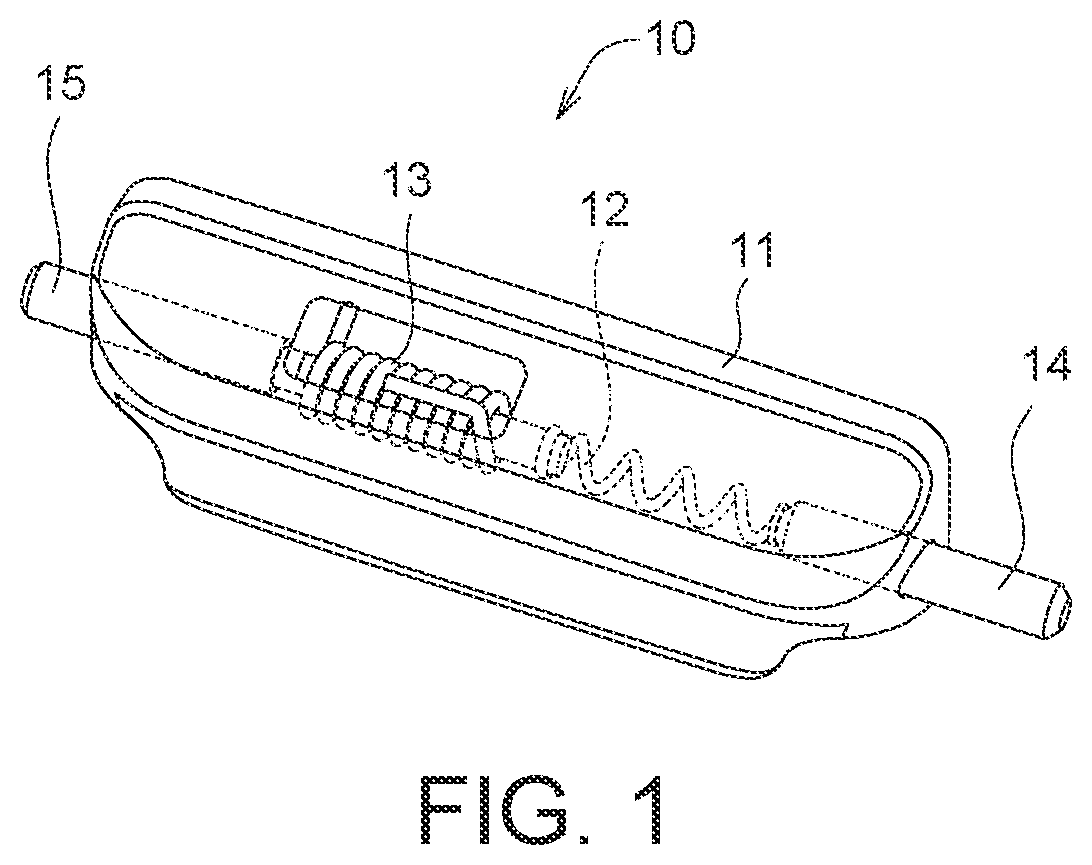
shows a schematic diagram of a band button according to an embodiment of the present invention;
A shows a schematic diagram of the base and the upper cover of the assembly jig before being assembled according to an embodiment of the present invention;
B shows a schematic diagram of the base and the upper cover of A after being assembled;
C shows a schematic diagram of a top view of the assembly jig of B ;
D shows a schematic diagram of a cross-sectional view of the assembly jig of C along a direction 2 D- 2 D′;
A shows a schematic diagram of the assembly jig of A further including a pressing mechanism (before the upper cover and the base are assembled);
B shows a schematic diagram of the upper cover and the base of A after being assembled;
A shows a schematic diagram of a front view of a first driving mechanism according to an embodiment of the present invention;
B shows a stereoscopic schematic diagram of the first driving mechanism of A ;
shows a schematic diagram of a first pressing component according to an embodiment of the present invention; and
A to 6 F show schematic diagrams of assembling the band button of using the assembly jig of B .
DETAILED DESCRIPTION OF PREFERRED EMBODIMENTS
Referring to to 5 , shows a schematic diagram of a band button 10 according to an embodiment of the present invention, A shows a schematic diagram of the base 110 and the upper cover 120 of the assembly jig 100 before being assembled according to an embodiment of the present invention, B shows a schematic diagram of the base 110 and the upper cover 120 of A after being assembled, C shows a schematic diagram of a top view of the assembly jig 100 of B , D shows a schematic diagram of a cross-sectional view of the assembly jig 100 of C along a direction 2 D- 2 D′, A shows a schematic diagram of the assembly jig 100 of A further including a pressing mechanism 140 (before the upper cover 120 and the base 110 are assembled), B shows a schematic diagram of the upper cover 120 and the base 110 of A after being assembled, A shows a schematic diagram of a front view of a first driving mechanism 150 according to an embodiment of the present invention, and B shows a stereoscopic schematic diagram of the first driving mechanism 150 of A , and shows a schematic diagram of a first pressing component 130 according to an embodiment of the present invention.
As shown in , the band button 10 may be connected to a watch strap, and then connected to a watch body (not shown) through a spring. The band button 10 includes a button body 11 , a compression spring 12 , a torsion spring 13 , a compression-spring positioning pin 14 and a torsion-spring positioning pin 15 , wherein the compression spring 12 , the torsion spring 13 , the compression-spring positioning pin 14 and the torsion-spring positioning pin 15 are disposed within the button body 11 .
As shown in A, 2 B, 3 A and 5 , the assembly jig 100 is suitable for assembling a band button 10 . The assembly jig 100 includes a base 110 , an upper cover 120 , a first pressing component 130 and a pressing mechanism 140 . The base 110 has an accommodating groove 110 r for accommodating the button body 11 , the compression spring 12 , the compression-spring positioning pin 14 and the torsion-spring positioning pin 15 . The upper cover 120 may be combined with the base 110 and has a slot 120 r for accommodating the torsion spring 13 . The first pressing component 130 is configured for pressing the torsion spring 13 into the button body 11 accommodated in the accommodating groove 110 r . The pressing mechanism 140 is configured for pressing the compression spring 12 , the compression-spring positioning pin 14 and the torsion-spring positioning pin 15 into the button body 11 accommodated in the accommodating groove 110 r . As a result, the band button 10 may be assembled through the assembly jig 100 , and accordingly various technical effects such as reducing assembly difficulty, increasing yield, reducing labor cost and/or increasing productivity may be achieved.
As shown in A , the accommodating groove 110 r includes a first sub-accommodating groove 110 r 1 , a second sub-accommodating groove 110 r 2 , and a third sub-accommodating groove 110 r 3 that communicate with each other. The first sub-accommodating groove 110 r 1 is configured for accommodating the button body 11 , the second sub-accommodating groove 110 r 2 is configured for accommodating the compression spring 12 and the compression-spring positioning pin 14 , and the third sub-accommodating groove 110 r 3 is configured for accommodating the torsion-spring positioning pin 15 . In the present embodiment, the second sub-accommodating groove 110 r 2 , the first sub-accommodating groove 110 r 1 and the third sub-accommodating groove 110 r 3 may be arranged along a moving direction, for example, the first direction D 1 or the second direction D 2 along the X-axis. The first sub-accommodating groove 110 r 1 is located between the second sub-accommodating groove 110 r 2 and the third sub-accommodating groove 110 r 3 . It is worth noting that the first sub-accommodating groove 110 r 1 , the second sub-accommodating groove 110 r 2 and the third sub-accommodating groove 110 r 3 are arranged in a straight line, so that the compression spring 12 , the compression-spring positioning pin 14 and the torsion-spring positioning pin 15 may be pressed into the button body 11 .
As shown in D , the upper cover 120 has a channel 120 a , and the channel 120 a extends linearly in an extending direction and communicates with the accommodating groove 110 r . For example, the channel 120 a extends in the third direction D 3 of the Z-axis, the extending direction and the moving direction are substantially perpendicular to each other (the first or second directions D 1 , D 2 are perpendicular to the third direction D 3 ). The torsion spring 13 may enter the button body 11 through the channel 120 a.
As shown in C and 2 D , the slot 120 r has a first wall 120 s 1 , a second walls 120 s 1 opposite to the first wall 120 s 1 , a third wall 120 s 3 , a fourth walls 120 s 4 opposite to the third wall 120 s 3 , an upper opening 120 r 1 and a lower opening 120 r 2 opposite to opposite to the upper opening 120 r 1 . The torsion spring 13 may be disposed within the slot 120 r through the upper opening 120 r 1 . The torsion spring 13 includes a spiral portion 13 A, a first end 13 B and a second end 13 C. The spiral portion 13 A is disposed between the first end 13 B and the second end 13 C. When the torsion spring 13 is in a free state, the first end 13 B and the second end 13 C may abut against the first wall 120 s 1 and the second wall 120 s 2 respectively, and accordingly it may prevent the torsion spring 13 from being separated from the upper cover 120 through the lower opening 120 r 2 .
As shown in C and 2 D , the lower opening 120 r 2 is smaller than the upper opening 120 r 1 . Furthermore, the third wall 120 s 3 and the fourth wall 120 s 4 are, for example, inclined surfaces. A distance H 1 between the third wall 120 s 3 and the fourth wall 120 s 4 gradually shrinks along a direction from the upper opening 120 r 1 to the lower opening 120 r 2 , so that an area of the lower opening 120 r 2 is smaller than that of the upper opening 120 r 1 . A projected area of the spiral portion 13 A projected on the lower opening 120 r 2 is equal to or smaller than an area of the lower opening 120 r 2 (it may be seen that the spiral portion 13 A of D protrudes with respect to the lower opening 120 r 2 ). Due the projected area of the spiral portion 13 A projected on the lower opening 120 r 2 being equal to or smaller than the area of the lower opening 120 r 2 , the deformed torsion spring 13 (the first end 13 B and the second end 13 C of the torsion spring 13 are deformed and retracted after being applied by force) may enter the accommodating groove 110 r by entirely passing through the lower opening 120 r 2 .
As shown in A , the pressing mechanism 140 is connected to the base 110 . The pressing mechanism 140 includes a first sliding seat 141 , a second sliding seat 142 , a second pressing component 143 and a third pressing component 144 . The first sliding seat 141 and the second sliding seat 142 are disposed on the base 110 . For example, the first sliding seat 141 and the second sliding seat 142 are movably disposed on the base 110 , wherein the first sliding seat 141 and the second sliding seat 142 are located at opposite two sides of the accommodating groove 110 r respectively.
As shown in A and 3 B , the second pressing component 143 is connected to (for example, fixed to) the first sliding seat 141 , and an end portion 143 a of the second pressing component 143 faces the compression-spring positioning pin 14 for pressing the compression spring 12 and the compression-spring positioning pin 14 into the button body 11 . In the present embodiment, the base 110 has a first lateral surface 110 s 1 and a first through hole 110 a 1 , wherein the first through hole 110 a 1 extends to the accommodating groove 110 r from the first lateral surface 110 s 1 . The second pressing component 143 is disposed through the first through hole 110 a 1 so that the end portion 143 a of the second pressing component 143 may be disposed in the second sub-accommodating groove 110 r 2 of the accommodating groove 110 r.
Similarly, as shown in A and 3 B , the third pressing component 144 is connected to (for example, fixed to) the second sliding seat 142 , and an end 144 a of the third pressing component 144 faces the torsion-spring positioning pin 15 for pressing the torsion-spring positioning pin 15 into the button body 11 . In the present embodiment, the base 110 has a second through hole 110 a 2 and a second lateral surface 110 s 2 opposite to the first lateral surface 110 s 1 . The second through hole 110 a 2 extends to the accommodating groove 110 r from the second lateral surface 110 s 2 . The third pressing component 144 is disposed through the second through hole 110 a 2 so that the end portion 144 a of the third pressing component 144 may be disposed in the third sub-accommodating groove 110 r 3 of the accommodating groove 110 r.
As shown in A and 3 B , the pressing mechanism 140 is movably connected to the base 110 . For example, the assembly jig 100 further includes a first elastic component 160 and a second elastic component 170 . The pressing mechanism 140 and the base 110 are connected through the first elastic component 160 and the second elastic component 170 , and accordingly the pressing mechanism 140 and the base 110 may move relatively. Furthermore, the first elastic component 160 connects the base 110 and the first sliding seat 141 . When the first sliding seat 141 moves along the first direction D 1 , the first elastic component 160 is deformed to store elastic potential energy. When the first elastic component 160 releases the elastic potential energy, it may provide the first sliding seat 141 with an elastic restoring force to restore the first sliding seat 141 along the second direction D 2 , thereby driving the second pressing component 143 to restore. Namely, the first sliding seat 141 return to an initial position. Similarly, the second elastic component 170 connects the base 110 and the second sliding seat 142 . The second direction D 2 and the first direction D 1 are opposite two directions. When the second sliding seat 142 moves along the second direction D 2 , the second elastic component 170 is deformed to store an elastic potential energy. When the second elastic component 170 releases the elastic potential energy, it may provide the second sliding seat 142 with an elastic restoring force to restore the second sliding seat 142 along the first direction D 1 , thereby driving the third pressing component 144 to restore. Namely, the second sliding seat 142 return to an initial position. In addition, the first elastic component 160 and/or the second elastic component 170 are, for example, the springs, such as the compression springs, but may also be other types.
As shown in A, 4 A and 4 B , the assembly jig 100 further includes a first driving mechanism 150 configure to drive the pressing mechanism 140 . The first driving mechanism 150 includes a cylinder 151 , a first piston rod 152 , a second piston rod 153 , a first connecting rod 154 and a second connecting rod 155 , wherein the cylinder 151 is, for example, an air pressure cylinder or an oil pressure cylinder, the first piston rod 152 is slidably disposed through a side of the cylinder 151 , and the second piston rod 153 is slidably disposed through another opposite side of the cylinder 151 . By the driving of the cylinder 151 , the first piston rod 152 and the second piston rod 153 may be extended or shortened relative to the cylinder 151 . The first piston rod 152 is connected to the first connecting rod 154 , and the first piston rod 152 may drive the first connecting rod 154 to move. When the first piston rod 152 moves along the first direction D 1 , the first connecting rod 154 moves along the first direction D 1 to drive the first sliding seat 141 and the second pressing component 143 to move along the first direction D 1 until the second pressing component 143 presses the compression spring 12 and the compression-spring positioning pin 14 into the button body 11 . When the first piston rod 152 moves along the second direction D 2 , the first connecting rod 154 releases the first sliding seat 141 . At the same time, the first elastic component 160 releases the elastic potential energy to drive the first sliding seat 141 and the second pressing component 143 to restore along the second direction D 2 .
Similarly, as shown in A, 4 A and 4 B , the second piston rod 153 is connected to the second connecting rod 155 , and the second piston rod 153 may drive the second connecting rod 155 to move. When the second piston rod 153 moves along the second direction D 2 , the second connecting rod 155 moves along the second direction D 2 to drive the second sliding seat 142 and the third pressing component 144 to move along the second direction D 2 until the third pressing component 144 presses the torsion-spring positioning pin 15 into the button body 11 . When the second piston rod 153 moves along the first direction D 1 , the second connecting rod 155 releases the second sliding seat 142 . At the same time, the second elastic component 170 releases the elastic potential energy to drive the second sliding seat 142 and the third pressing component 144 to restore along the first direction D 1 .
The assembly process of the band button 10 of is described below.
Referring to A to 6 F , A to 6 F show schematic diagrams of assembling the band button 10 of using the assembly jig 100 of B .
As shown in A , the base 110 , the pressing mechanism 140 , the first elastic component 160 and the second elastic component 170 are provided. The pressing mechanism 140 and the base 110 are relatively movable. For example, the pressing mechanism 140 and the base 110 are connected to be relatively movable through the first elastic component 160 and the second elastic component 170 .
As shown in A , the base 110 has an accommodating groove 110 r , and the accommodating groove 110 r includes the first sub-accommodating groove 110 r 1 , the second sub-accommodating groove 110 r 2 and the third sub-accommodating groove 110 r 3 that communicate with each other.
As shown in A , the pressing mechanism 140 includes the first sliding seat 141 , the second sliding seat 142 , the second pressing component 143 and the third pressing component 144 . The second pressing component 143 is connected to the first sliding seat 141 . In the present embodiment, the base 110 has the first lateral surface 110 s 1 and the first through hole 110 a 1 , wherein the first through hole 110 a 1 extends to the accommodating groove 110 r from the first lateral surface 110 s 1 . The second pressing component 143 is disposed through the first through hole 110 a 1 so that the end portion 143 a of the second pressing component 143 may be disposed in the second sub-accommodating groove 110 r 2 of the accommodating groove 110 r . The third pressing component 144 is connected to the second sliding seat 142 . In the present embodiment, the base 110 has the second through hole 110 a 2 and the second lateral surface 110 s 2 opposite to the first lateral surface 110 s 1 . The second through hole 110 a 2 extends to the accommodating groove 110 r from the second lateral surface 110 s 2 . The third pressing component 144 is disposed through the second through hole 110 a 2 so that the end portion 144 a of the third pressing component 144 may be disposed in the third sub-accommodating groove 110 r 3 of the accommodating groove 110 r.
As shown in B , the button body 11 , the compression spring 12 , the compression-spring positioning pin 14 and the torsion-spring positioning pin 15 are disposed in the accommodating groove 110 r of the base 110 , wherein the button body 11 is disposed in the first sub-accommodating groove 110 r 1 , the compression spring 12 and the compression-spring positioning pin 14 are disposed in the second sub-accommodating groove 110 r 2 , and the torsion-spring positioning pin 15 is disposed in the third sub-accommodating groove 110 r 3 . In an embodiment, the button body 11 , the compression spring 12 , the compression-spring positioning pin 14 and the torsion-spring positioning pin 15 may be disposed in the accommodating groove 110 r at the same assembly station. Alternatively, one or some of the button body 11 , the compression spring 12 , the compression-spring positioning pin 14 and the torsion-spring positioning pin 15 may be disposed in the accommodating groove 110 r at the same assembly station, while another or others may be disposed in the accommodating groove 110 r at another assembly station.
Then, as shown in C , the base 110 and the upper cover 120 are combined. For example, the upper cover 120 is moved to cover the base 110 .
Then, as shown in D , the torsion spring 13 is disposed in the slot 120 r of the upper cover 120 .
Then, as shown in E , the first pressing component 130 presses the torsion spring 13 into the button body 11 . For example, the first pressing component 130 presses the torsion spring 13 into the button body 11 through the channel 120 a . In addition, a second driving mechanism 131 (shown in ) may be used to drive the first pressing component 130 to press the torsion spring 13 into the button body 11 .
Then, as shown in F , the cylinder 151 of the first driving mechanism 150 (shown in A ) drives the first sliding seat 141 along the first direction D 1 so as to move the second pressing component 143 to press the compression spring 12 and the compression-spring positioning pin 14 into the button body 11 , and the cylinder 151 (shown in A ) of the first driving mechanism 150 drives the second sliding seat 142 along the second direction D 2 so as to move the third pressing component 144 to press the torsion-spring positioning pin 15 into the button body 11 . So far, the assembly of the band button 10 is completed.
In addition, the first sliding seat 141 and the second sliding seat 142 may be driven at the same time, or started or performed at different time points respectively.
As shown in F , during the movement of the first sliding seat 141 along the first direction D 1 , the first elastic component 160 is deformed to store the elastic potential energy. During the movement of the second sliding seat 142 along the second direction D 2 , the second elastic component 170 is deformed to store the elastic potential energy. After the compression spring 12 , the compression-spring positioning pin 14 and the torsion-spring positioning pin 15 are pressed into the button body 11 , under the driving of the cylinder 151 (shown in A ) of the first driving mechanism 150 , the first connecting rod 154 drives the first sliding seat 141 to move along the second direction D 2 . At this time, the first elastic component 160 releases the elastic potential energy to provide the first sliding seat 141 quickly restore. Similarly, under the driving of the cylinder 151 (shown in A ) of the first driving mechanism 150 , the second connecting rod 155 drives the second sliding seat 142 to move along the first direction D 1 . At this time, the second elastic component 170 releases the elastic potential energy to provide the second sliding seat 142 quickly restore.
The restoring of the first sliding seat 141 and the restoring of the second sliding seat 142 may be started or performed at the same time, or started or performed at different time points.
After the assembly of the band button 10 is completed, the upper cover 120 and the base 110 are separated, and accordingly the assembled band button 10 may be taken out.
In addition, the assembly steps of the aforementioned each assembly station may be performed, by a manual way, a driving mechanism and/or by a robotic arm.
To sum up, an embodiment of the present invention submits an assembly jig and an assembly method using the same. The assembly jig at least includes a base, an upper cover and a pressing mechanism, wherein the base has an accommodating groove, and the accommodating groove may accommodate the button body, the compression spring and the compression-spring positioning pin. The upper cover may be combined with the base and has a slot. The slot is configured to accommodate the torsion spring, the pressing mechanism may press the compression spring, the compression-spring positioning pin and the torsion-spring positioning pin into the button body. In addition, a pressing component may press the torsion spring into the button body. As a result, the band button may be automatically assembled using an assembly jig, which may reduce assembly difficulty, increase yield, reduce labor cost and/or increase productivity.
While the invention has been described in terms of what is presently considered to be the most practical and preferred embodiments, it is to be understood that the invention needs not be limited to the disclosed embodiment. On the contrary, it is intended to cover various modifications and similar arrangements included within the spirit and scope of the appended claims which are to be accorded with the broadest interpretation so as to encompass all such modifications and similar structures.
Figures (16)
Citations
This patent cites (4)
- US4217681
- US11033082
- US105234658
- US105234658