Abstract
A fluid discharger includes: a discharge nozzle configured to discharge fluid; a first rotation device configured to rotate the discharge nozzle; and a control device configured to control the first rotation device by remote operation. The control device includes a first mode control unit including a first automatic control unit configured to automatically perform reciprocating control of the discharge nozzle in a first rotation range set for each of the fluid dischargers; and a first switching unit configured to switch between a control signal to be outputted from the first automatic control unit and a control signal to rotate the discharge nozzle by a first rotation angle designated by remote operation. In a dust suppression system, this configuration can control the direction of the discharge nozzle by remote operation, and also can automatically reciprocate the direction of the discharge nozzle within a predetermined range.
Claims (9)
1. A dust suppression system comprising one or more fluid dischargers configured to discharge a fluid capable of suppressing generation of dust to a work area of an object to be worked by remote operation, wherein: the fluid discharger includes a discharge nozzle configured to discharge the fluid, a first rotation device configured to rotate the discharge nozzle, and a control device configured to control the first rotation device by remote operation; the control device includes a first mode control unit including a first automatic control unit configured to automatically perform reciprocating control of the discharge nozzle in a first rotation range set for each of the fluid dischargers, and a first switching unit configured to switch between a first automatic signal to be outputted from the first automatic control unit and a first operation signal to rotate the discharge nozzle by a first rotation angle designated by the remote operation; and the first automatic control unit includes: a first lower limit setting unit configured to set a lower limit angle of the first rotation range; a first upper limit setting unit configured to set an upper limit angle of the first rotation range; a first lower limit comparison unit configured to compare between a first lower limit angle set by the first lower limit setting unit and a first rotation displacement angle outputted from the first rotation device; a first upper limit comparison unit configured to compare between a first upper limit angle set by the first upper limit setting unit and the first rotation displacement angle; and a first signal reversing unit configured to, in a case in which a result of either the first lower limit comparison unit or the first upper limit comparison unit is different from a previous result, reverse the first automatic signal that was outputted last time and output the reversed signal.
Show 8 dependent claims
2. The dust suppression system according to claim 1 , wherein the first switching unit is controlled by remote operation.
3. The dust suppression system according to claim 1 , wherein the first lower limit setting unit and the first upper limit setting unit are set in the fluid discharger.
4. The dust suppression system according to claim 1 , wherein: the fluid discharger further includes a second rotation device that is controlled by the control unit to rotate the discharge nozzle around a rotational axis orthogonal to a rotational axis of the first rotation device; and the control unit includes a second mode control unit including a second automatic control unit configured to automatically perform reciprocating control of the discharge nozzle in a second rotation range set for each of the fluid dischargers; and a second switching unit configured to switch between a second automatic signal to be outputted from the second automatic control unit and a second operation signal to rotate the discharge nozzle by a second rotation angle designated by the remote operation.
5. The dust suppression system according to claim 4 , wherein the second switching unit is controlled by remote operation.
6. The dust suppression system according to claim 4 , wherein the second automatic control unit includes: a second lower limit setting unit configured to set a lower limit angle of the second rotation range; a second upper limit setting unit configured to set an upper limit angle of the second rotation range; a second lower limit comparison unit configured to compare between a second lower limit angle set by the second lower limit setting unit and a second rotation displacement angle outputted from the second rotation device; a second upper limit comparison unit configured to compare between a second upper limit angle set by the second upper limit setting unit and the second rotation displacement angle; and a second signal reversing unit configured to, in a case in which a result of either the second lower limit comparison unit or the second upper limit comparison unit is different from a previous result, reverse the second automatic signal that was outputted last time and output the reversed signal.
7. The dust suppression system according to claim 6 , wherein the second lower limit setting unit and the second upper limit setting unit are set in the fluid discharger.
8. The dust suppression system according to claim 1 , wherein the fluid includes water or a foamy material.
9. The dust suppression system according to claim 1 , wherein the remote operation is performed from a single transmitter to the multiple fluid dischargers.
Full Description
Show full text →
TECHNICAL FIELD
The present invention relates to a dust suppression system
BACKGROUND ART
Due to the nature of civil engineering work, construction work, demolition work, and the like, dust and the like (hereinafter, simply referred to as dust_) is often generated at worksites. Particularly in demolition work of (all or part of) buildings (objects to be demolished), generation of dust at work sites is unavoidable. If measures against dust are not taken, not only will working environments deteriorate, but also the dust will be scattered in surrounding areas, causing discomfort to residents living near the site, and in some cases, leading to health hazards. Therefore, various measures have been devised to control dust dispersion during demolition work.
For example, a dust suppression system with a fluid discharger disclosed in Patent Literature 1, in particular, controls the direction(s) of a discharge nozzle(s) of one or more fluid dischargers with two rotation devices by remote operation, and controls, with an open/close valve, the amount of fluid to be discharged, so that the fluid is discharged efficiently and accurately to a work area at a work site.
Therefore, the use of the fluid discharger according to Patent Literature 1 can eliminate the need for a worker who sprays water to suppress the scattering of dust associated with demolition work. In other words, since there can be no need to place such a worker in the vicinity of a work machine performing demolition work, it is possible to limit the exposure of the worker to dust, and make a work environment safer for workers while saving water at work sites.
CITATION LIST
Patent Literature
•
• Patent Literature 1: Japanese Patent Application Laid-Open No. 2015-227568
SUMMARY OF INVENTION
Technical Problem
However, in the fluid discharger shown in Patent Literature 1, the direction of the discharge nozzle is necessary to be controlled by remote operation. Therefore, in a case in which the direction of the discharge nozzle reciprocates within a predetermined range in order to suppress the dust generated from the entirety of a specific area, an operator needs to instruct and control the direction of the discharge nozzle one by one. In other words, in the case of trying to control multiple fluid dischargers, it is necessary to focus solely on the control of fluid dischargers for suppressing the dust generated from the whole specific area. In other words, in such a case, it could be difficult to remotely operate the multiple fluid dischargers effectively.
Therefore, the present invention was made to solve the aforementioned problems, and an object of the present invention is to provide a dust suppression system that can control the direction of a discharge nozzle by remote operation, while automatically reciprocating the direction of the discharge nozzle within a predetermined range.
Solution to Problem
To solve the aforementioned object, the present invention is a dust suppression system including one or more fluid dischargers configured to discharge a fluid capable of suppressing generation of dust to a work area of an object to be worked by remote operation, the fluid discharger including: a discharge nozzle configured to discharge the fluid; a first rotation device configured to rotate the discharge nozzle; and a control device configured to control the first rotation device by remote operation. In this dust suppression system, the control device includes a first mode control unit including a first automatic control unit configured to automatically perform reciprocating control of the discharge nozzle in a first rotation range set for each of the fluid dischargers; and a first switching unit configured to switch between a first automatic signal to be outputted from the first automatic control unit and a first operation signal to rotate the discharge nozzle by a first rotation angle designated by remote operation wherein, the first automatic control unit includes: a first lower limit setting unit configured to set a lower limit angle of the first rotation range; a first upper limit setting unit configured to set an upper limit angle of the first rotation range; a first lower limit comparison unit configured to compare between a first lower limit angle set by the first lower limit setting unit and a first rotation displacement angle outputted from the first rotation device; a first upper limit comparison unit configured to compare between a first upper limit angle set by the first upper limit setting unit and the first rotation displacement angle; and a first signal reversing unit configured to, in a case in which a result of either the first lower limit comparison unit or the first upper limit comparison unit is different from a previous result, reverse the first automatic signal that was outputted last time and output the reversed signal.
In the present invention, the control device includes the first mode control unit including the first automatic control unit configured to automatically perform reciprocating control of the discharge nozzle within the first rotation range, and the first switching unit configured to switch between the first automatic signal to be outputted from the first automatic control unit and the first operation signal to rotate the discharge nozzle by the first rotation angle designated by remote operation. That is, since the first switching unit can switch between the first automatic signal and the first operation signal, it is possible to control the discharge nozzle at the first rotation angle by remote operation, and it is also possible to automatically perform reciprocating control of the discharge nozzle within the first rotation range.
In a case in which the first switching unit is controlled by remote operation, it is possible, by remote operation, to switch between control of the discharge nozzle at the first rotation angle and automatic reciprocating control of the discharge nozzle without physically approaching the fluid discharger, thus saving time and effort (amount of work and man-hours) required to switch between these two.
The discharge nozzle can automatically reciprocates within the first rotation range by simple control at low cost, since the first automatic control unit includes: a first lower limit setting unit configured to set a lower limit angle of the first rotation range; a first upper limit setting unit configured to set an upper limit angle of the first rotation range; a first lower limit comparison unit configured to compare between a first lower limit angle set by the first lower limit setting unit and a first rotation displacement angle outputted from the first rotation device; a first upper limit comparison unit configured to compare between a first upper limit angle set by the first upper limit setting unit and the first rotation displacement angle; and a first signal reversing unit configured to, in a case in which a result of either the first lower limit comparison unit or the first upper limit comparison unit is different from a previous result, reverse the first automatic signal that was outputted last time and output the reversed signal.
In a case in which the first lower limit setting unit and the first upper limit setting unit are set in the fluid discharger, it is possible to eliminate time and effort required to set the first rotation range by remote operation and a configuration for transmitting data of the first rotation range to the fluid discharger, thus promoting cost reduction.
In a case in which the fluid discharger further includes a second rotation device that is controlled by the control unit to rotate the discharge nozzle around a rotational axis orthogonal to a rotational axis of the first rotation device, and the control unit includes a second mode control unit including: a second automatic control unit configured to automatically perform reciprocating control of the discharge nozzle in a second rotation range set for each of the fluid dischargers; and a second switching unit configured to switch between a second automatic signal to be outputted from the second automatic control unit and a second operation signal to rotate the discharge nozzle by a second rotation angle designated by remote operation, the second switching unit can switch between the second automatic signal and the second operation signal, so it is possible to control the discharge nozzle by remote operation at a second rotation angle, and it is also possible to automatically perform reciprocating control of the discharge nozzle within the second rotation range.
In a case in which the second switching unit is controlled by remote operation, it is possible to switch between control of the discharge nozzle at the second rotation angle and automatic reciprocating control of the discharge nozzle by remote operation without physically approaching the fluid discharger, thus saving time and effort (amount of work and man-hours) required to switch between these two.
The discharge nozzle can automatically reciprocates within the second rotation range by simple control at low cost, in a case in which the second automatic control unit includes: a second lower limit setting unit configured to set a lower limit angle of the second rotation range; a second upper limit setting unit configured to set an upper limit angle of the second rotation range; a second lower limit comparison unit configured to compare between a second lower limit angle set by the second lower limit setting unit and a second rotation displacement angle out putted from the second rotation device; a second upper limit comparison unit configured to compare between a second upper limit angle set by the second upper limit setting unit and the second rotation displacement angle; and a second signal reversing unit configured to, in a case in which a result of either the second lower limit comparison unit or the second upper limit comparison unit is different from a previous result, reverse the second automatic signal that was outputted last time and output the reversed signal.
In a case in which the second lower limit setting unit and the second upper limit setting unit are set in the fluid discharger, it is possible to eliminate time and effort required to set the second rotation range by remote operation and a configuration for transmitting data of the second rotation range to the fluid discharger, thus promoting cost reduction.
In a case in which the fluid includes water or a foamy material, when the fluid is water, the object to be worked can be effectively wetted. When the fluid is the foamy material, excessive discharge of water can be avoided, and the amount of water used can be greatly reduced, thus saving water as compared to the case of only sprinkling water.
In the case of performing the remote operation from a single transmitter to the multiple fluid dischargers, the number of workers operating the fluid dischargers can be reduced, and the multiple fluid dischargers can be operated efficiently.
Advantageous Effects of Invention
According to the present invention, in a dust suppression system it is possible to control the direction of a discharge nozzle by remote operation, while automatically reciprocating the direction of the discharge nozzle within a predetermined range. Therefore, it is possible to effectively remotely control multiple fluid dischargers.
BRIEF DESCRIPTION OF DRAWINGS
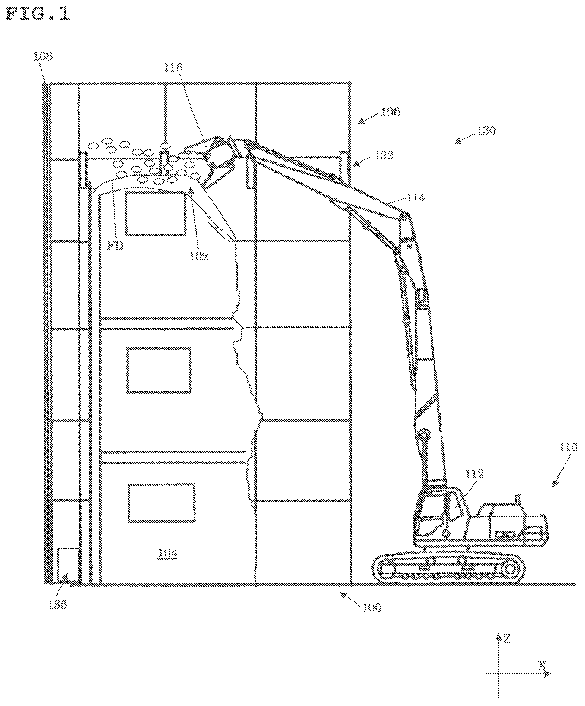
is a side view illustrating an example of a dust suppression system according to a first embodiment of the present invention used at a work site;
A is a perspective view illustrating a fluid discharger used in the dust suppression system in ;
B is a schematic diagram illustrating a fluid supply for supplying a fluid to the fluid discharger in A ;
A is a block diagram of a transmitter used in the dust suppression system in ;
B is a block diagram of the fluid discharger in A ;
A is a block diagram of a first mode control unit of a control device of the fluid discharger in B ;
B is a block diagram of a signal reversing unit of the first mode control unit in A ;
C is a block diagram of a second mode control unit of the control device of the fluid discharger in B ;
A is a perspective view of a transmitter used in the dust suppression system in ;
B is a perspective view of a receiver of the fluid discharger in A ;
C is a plan view illustrating an input part of the control unit of the fluid discharger in A ;
A is a front view of a fluid discharger of a dust suppression system according to a second embodiment of the present invention;
B is a side view illustrating the fluid discharger in A ;
A is a top view of the fluid discharger in A in which a casing and the like are made transparent;
B is a bottom view of the fluid discharger in A in which the casing and the like are made transparent;
A is a side view illustrating a configuration around a discharge nozzle of the fluid discharger in A ;
B is a side view illustrating a configuration around an open/close valve of the fluid discharger in A ;
A is a bottom view illustrating a second rotation mechanism that rotates a rotation member of the fluid discharger in A ;
B is a side view illustrating the second rotation mechanism in A ; and
C is a side view illustrating the relationship between a pulley and a wire of the second rotation mechanism in B .
DESCRIPTION OF EMBODIMENTS
An example of a first embodiment of the present invention will be herein after described in detail with reference to the drawings.
First, a work site 100 where a dust suppression system 130 according to the present embodiment is used will be described.
As illustrated in , scaffolding 106 is built around the work site 100 , and a curing sheet 108 is attached to the outside of the scaffolding 106 . A building 104 , which is an object to be worked on, is located at the work site 100 inside the scaffolding 106 . In the building 104 , a work area 102 , which is a part (encircled part) covered with a fluid FD sprayed from a fluid discharger 132 of the dust suppression system 130 to be described later, is demolished by a work machine 110 . The work machine 110 can move freely in any direction, for example, by crawler tracks. The work machine 110 is provided with a cab 112 . From the cab 112 , a work attachment 116 at an end of an arm 114 and the crawler tracks can be freely operated (by a worker or a remotely operated robot in the cab 112 ). In the present embodiment, the work attachment 116 is a crushing tool, and the work machine 110 is a so-called ‘crusher._ The fluid discharger 132 can be remotely operated by a transmitter (not illustrated) brought into the cab 112 (the transmitter may be operated from outside the cab 112 ). The work area 102 includes an area where the work attachment 116 comes into direct contact with the building 104 and where dust is directly generated by demolition with the work attachment 116 . The fluid FD may be water or any flowable foamy material including air bubbles.
Next, the schematic configuration of the dust suppression system 130 according to the present invention will be described with reference to A .
The dust suppression system 130 has one or more fluid dischargers 132 configured to discharge the fluid FD, capable of suppressing the generation of dust to the work area 102 of the building 104 , by remote operation with one transmitter 134 ( A ). As illustrated in A , the fluid discharger 132 includes a control mechanism 146 configured to control the discharge direction of the fluid FD by receiving a transmission signal SC from the transmitter 134 , and a support frame 172 configured to detachably support the control mechanism 146 in its own radial and vertical directions. The fluid discharger 132 includes a discharge nozzle 178 D configured to discharge the fluid FD, a first rotation device 166 configured to rotate the discharge nozzle 178 D, a second rotation device 168 configured to rotate the discharge nozzle 178 D around a rotational axis (axial center O 2 ) orthogonal to the rotational axis (axial center O 1 ) of the first rotation device 166 , and a control device 156 ( B ) configured to control the first rotation device 166 and the second rotation device 168 by remote operation.
In the present embodiment, the output and frequency of the transmitter 134 and a receiver 148 are determined in conformity with the standards of the specified low-power radio station defined by the radio law. Therefore, the transmitter 134 can be remotely operated at a distance of 50 m to 100 m from the fluid discharger 132 . In the present embodiment, the fluid discharger 132 is less than 1 m in size (e.g., WL 300 mm j, H 600 mm) and less than 20 kg.
The details of each component (member) of the transmitter 134 and the fluid discharger 132 will be described below.
The transmitter 134 is in a portable rectangular parallelepiped shape as illustrated in A , and has a control signal input 136 , a CH selector 138 , a local oscillator 140 , a modulation circuit 142 , and a power supply 144 as illustrated in A . The reference sign PSW is a power switch of the transmitter 134 (also the reference sign PSW in B ).
As illustrated in A , the control signal input 136 has two horizontal rotation instruction buttons 136 A, two vertical rotation instruction buttons 136 B, and two open-close instruction buttons 136 C. The horizontal rotation instruction buttons 136 A include a button that outputs a signal to instruct right rotation of a rotation member 176 and a button that outputs a signal to instruct left rotation of the rotation member 176 . The vertical rotation instruction buttons 136 B include a button that outputs a signal to instruct an increase of a first rotation angle j relative to a horizontal direction of the discharge nozzle 178 D and a button that outputs a signal to instruct a decrease of the first rotation angle j relative to a horizontal direction of the discharge nozzle 178 D. The open-close instruction buttons 136 C include a button that outputs a signal to instruct an open state of an open/close valve 170 A of a valve drive device 170 (not illustrated) and a button that outputs a signal to instruct a close state of the open/close valve 170 A. As illustrated in A , as long as the worker presses any of the buttons, a control signal SA (6-bit signal) corresponding to the button is outputted from the control signal input 136 .
In the present embodiment, by simultaneously pressing two of the horizontal rotation instruction buttons 136 A and further pressing the upper one of the open-close instruction buttons 136 C, it is possible to instruct the rotation member 176 (=discharge nozzle 178 D) to automatically reciprocate in the horizontal direction. Conversely, by simultaneously pressing two of the horizontal rotation instruction buttons 136 A and further pressing the lower one of the open-close instruction buttons 136 C, the automatic reciprocation of the rotation member 176 in the horizontal direction can be canceled and the horizontal rotation of the rotation member 176 can be controlled by an instruction from the transmitter 134 . In addition, by simultaneously pressing two of the vertical rotation instruction buttons 136 B and further pressing the upper one of the open-close instruction buttons 136 C, the automatic reciprocation of the discharge nozzle 178 D in the vertical direction can be instructed. Conversely, by simultaneously pressing two of the vertical rotation instruction buttons 136 B and further pressing the lower one of the open-close instruction buttons 136 C, the automatic reciprocation of the discharge nozzle 178 D in the vertical direction can be canceled and the vertical rotation of the discharge nozzle 178 D can be controlled by an instruction from the transmitter 134 .
As illustrated in A , a CH selector 138 includes a frequency selector 138 A, a number select or 138 B, and a power switch PSW, and outputs a signal identifying a fluid discharger 132 to be controlled. As illustrated in A , the frequency selector 138 A provides an output to determine one of a plurality of carrier frequencies fi (i=1 to 4 in the present embodiment) provided in a specific frequency band handled in the local oscillator 140 . The number selector 138 B provides an output that defines one of the numbers j (j=1 to 4 in the present embodiment) for identifying the fluid discharger 132 . Therefore, up to 16 (=4*4) fluid dischargers 132 can be identified by selection of the CH selector 138 , and different identification signals SB can be transmitted to the respective fluid dischargers 132 . In the present embodiment, the 6-bit control signal SA from the control signal input 136 and the 2-bit identification signal SB from the number select or 138 B generate an 8-bit transmission signal SC.
As illustrated in A , the local oscillator 140 is connected to an output of the CH selector 138 , and generates and outputs a carrier frequency fi determined by the frequency selector 138 A.
As illustrated in A , the modulation circuit 142 is connected to an output of the control signal input 136 , an output of the CH selector 138 , and an output of the local oscillator 140 . The modulation circuit 142 is configured to modulate the carrier frequency fi with the transmission signal SC and radiate the modulated carrier frequency as a radio wave from an antenna. The power supply 144 is specifically a battery of various types, and supplies necessary power to each of the above-described components of the transmitter 134 .
As illustrated in B , the control mechanism 146 of the fluid discharger 132 includes the receiver 148 , the control device 156 , the first rotation device 166 , the second rotation device 168 , and the valve drive device 170 .
The receiver 148 is in a rectangular parallelepiped shape as illustrated in B , and the receiver 148 is configured integrally with the control device 156 . As illustrated in B , the receiver 148 has a CH selector 150 , a local oscillator 152 , and a demodulator circuit 154 , and receives the transmission signal SC from the transmitter 134 .
As illustrated in B , the CH selector 150 includes a frequency selector 150 A, a number selector 150 B, and a power switch PSW. The frequency selector 150 A and the number selector 150 B have the same function as those of the frequency selector 138 A and the number selector 138 B, respectively, so the description thereof is omitted. The number selector 150 B outputs a 2-bit identification signal SF to the control device 156 . The local oscillator 152 illustrated in B has the same function as that of the local oscillator 140 , so the description thereof is omitted.
As illustrated in B , the demodulator circuit 154 has the function of demodulating the radio wave received by the antenna and outputting an 8-bit reception signal SE to the control device 156 . In other words, in a case in which a carrier frequency fk (k=1 to 4 in the present embodiment) identified by the frequency selector 150 A is the same as the carrier frequency fi (fk=fi) and the identification signal SF is the same as the identification signal SB (SF=SB), a demodulated reception signal SE is the same as the transmission signal SC (SE=SC). In a case in which the carrier frequency fk is not the same as the carrier frequency fi, the radio wave received by the antenna is not demodulated and the demodulator circuit 154 does not output the reception signal SE.
As illustrated in B , the control device 156 includes a logic circuit 158 , a switch circuit 160 , a first mode control unit 161 A, a second mode control unit 161 B, a drive circuit 162 , and a power supply 164 . The controller 156 controls the first rotation device 166 , the second rotation device 168 , and the valve drive device 170 according to the reception signal SE outputted from the receiver 148 .
As illustrated in B , the logic circuit 158 is connected to an output of the demodulator circuit 154 of the receiver 148 and an output of the CH selector 150 thereof. With the identification signal SF, the logic circuit 158 discerns an identification signal SD 1 , which identifies a fluid discharger 132 , from the reception signal SE. In other words, the logic circuit 158 compares the 2-bit identification signal SD 1 of the reception signal SE with the 2-bit identification signal SF from the number selector 150 B of the CH selector 150 . The logic circuit 158 outputs an ON signal as a control signal SG in a case in which the identification signal SD 1 and the identification signal SF are the same as each other, and outputs an OFF signal as the control signal SG in a case in which the identification signal SD 1 and the identification signal SF are different from each other.
As illustrated in B , the switch circuit 160 is connected to an output of the demodulator circuit 154 and an output of the logic circuit 158 . The switch circuit 160 conducts the turning ON/OFF of a control signal SD, which controls the first rotation device 166 , the second rotation device 168 , and the valve drive device 170 , of the reception signal SE according to an output of the logic circuit 158 . In other words, the switch circuit 160 conducts the turning ON/OFF of the 6-bit control signal SD by an ON/OFF signal from the logic circuit 158 . That is, in a case in which the setting of the CH selector 138 of the transmitter 134 and the setting of the CH selector 150 of the receiver 148 are the same as each other, the 6-bit control signal SA (=SD, SH, SP), inputted by the control signal input 136 of the transmitter 134 , and a 2-bit control signal SX are outputted from the switch circuit 160 . The control signal SX is a 2-bit signal corresponding to the two open-close instruction buttons 136 C.
As illustrated in B , the first mode control unit 161 A is connected to the switch circuit 160 and an output of the first rotation device 166 . The first mode control unit 161 A outputs a control signal SI to the first drive circuit 162 A. As illustrated in A , the first mode control unit 161 A includes a first automatic control unit 161 AA and a first switching unit 161 AH. The first automatic control unit 161 AA automatically controls the discharge nozzle 178 D to reciprocate in a first rotation range jr, which is set for each fluid discharger 132 . The first switching unit 161 AH switches between a control signal (first automatic signal) SN, outputted from the first automatic control unit 161 AA, and a control signal (first operation signal) SH 2 to rotate the discharge nozzle 178 D by the first rotation angle j designated by remote operation. For this reason, a case in which the first switching unit 161 AH outputs the control signal SN is referred to as a first automatic mode, and a case in which the first switching unit 161 AH outputs the control signal SH 2 is referred to as a first manual mode. A first rotation displacement angle j 0 refers to a rotation angle of the discharge nozzle 178 D outputted from the first rotation device 166 , and the first rotation displacement angle j 0 is obtained by a displacement signal SO from a potentiometer attached to (a first rotation shaft 166 A of) the first rotation device 166 .
Here, as illustrated in A , the first automatic control unit 161 AA has a first lower limit setting unit 161 AC, a first upper limit setting unit 161 AB, a first lower limit comparison unit 161 AE, a first upper limit comparison unit 161 AD, and a first signal reversing unit 161 AF. The first lower limit setting unit 161 AC and the first upper limit setting unit 161 AB are, for example, variable resistors, and as illustrated in C , the first lower limit setting unit 161 AC and the first upper limit setting unit 161 AB are set at an input unit 156 A of the control device 156 of the fluid discharger 132 . The input unit 156 A is provided at a position visible from outside the fluid discharger 132 .
As illustrated in C , the first lower limit setting unit 161 AC sets a lower limit angle (first lower limit angle) j 1 of the first rotation range jr by specifying an angle j 1 downward from a center angle jC (for example, in the case of the center angle jC=0, the angle j 1 is a negative value). The signal set at this time is referred to as a lower limit signal SK. In the same manner, the first upper limit setting unit 161 AB sets an upper limit angle (first upper limit angle) j 2 of the first rotation range jr by specifying an angle j 2 upward from the center angle jC (for example, in the case of the center angle jC=0, the angle j 2 is a positive value). The signal set at this time is referred to as an upper limit signal SJ. As a result, the first rotation range jr is −j 1 +j 2 . The center angle jC (=0) can be set to an angle exactly at the center of a rotatable range of the discharge nozzle 178 D.
As illustrated in A , the first lower limit comparison unit 161 AE compares the first lower limit angle j 1 , set by the first lower limit setting unit 161 AC, with a first rotation displacement angle j 0 (for example, in a case in which the first rotation displacement angle j 0 is the central angle jC, the first rotation displacement angle j 0 is zero). The first lower limit comparison unit 161 AE, for example, outputs a H-level control signal SM in a case in which the first rotation displacement angle j 0 is the same as or less than the first lower limit angle j 1 . Conversely, in a case in which the first rotation displacement angle j 0 is greater than the first lower limit angle j 1 , the first lower limit comparison unit 161 AE outputs a L-level control signal SM. The first upper limit comparison unit 161 AD compares the first upper limit angle j 2 , set by the first upper limit setting unit 161 AB, with the first rotation displacement angle j 0 . The first upper limit comparison unit 161 AD, for example, outputs a H-level control signal SL in a case in which the first rotation displacement angle j 0 is the same as or greater than the first upper limit angle j 2 . Conversely, in a case in which the first rotation displacement angle j 0 is less than the first upper limit angle j 2 , the first upper limit comparison unit 161 AD outputs a L-level control signal SL.
In a case in which a result of either the first lower limit comparison unit 161 AE or the first upper limit comparison unit 161 AD is different from a previous result, the first signal reversing unit 161 AF, illustrated in A , reverses and outputs the control signal SN that was previously outputted. In other words, for example, in a case in which the first rotation displacement angle j 0 is the same as or less than the first lower limit angle j 1 , the first rotation displacement angle j 0 is less than the first upper limit angle j 2 , and the control signal SM is the H level and the control signal SL is the L level. In this case, the 2-bit control signal SN that has been outputted to the first switching unit 161 AH is reversed (for example, in a case in which control signals SN 1 and SN 2 are the H level and the L level, the control signals SN 1 and SN 2 are made to be the L level and the H level, respectively). After reversing, the control signal SN remains outputted and unchanged until the first rotation displacement angle j 0 becomes greater than the first lower limit angle j 1 and the first rotation displacement angle j 0 becomes the same as or greater than the first upper limit angle j 2 . In a case in which the first rotation displacement angle j 0 becomes the same as or greater than the first upper limit angle j 2 , the first rotation displacement angle j 0 is greater than the first lower limit angle j 1 , so the control signal SM becomes the L level and the control signal SL becomes the H level. At this time, the 2-bit control signal SN that had been outputted to the first switching unit 161 AH is further reversed. During automatic driving, this operation is repeated.
For this purpose, as illustrated in B , the first signal reversing unit 161 AF is constituted of, for example, a combination of two signal holding units 161 AG. In principle, ON-side terminals On 1 and On 2 and OFF-side terminals Off 1 and Off 2 of the two signal holding units 161 AG are connected in parallel by crossing each other, so that the control signal SN 1 or the control signal SN 2 outputted is the H level. For example, the upper bits of the control signal SN can be used as the control signal SN 1 and the lower bits of the control signal SN can be used as the control signal SN 2 .
For example, as illustrated in B , the signal holding unit 161 AG is constituted of two NOT circuits IN 1 and IN 2 , a NAND circuit ND, and a diode DI. In a case in which both of the control signals SL and SM become the L level, only the control signal (SN 1 or SN 2 ) of the signal holding unit 161 AG, which was the H level at the ON-side terminal On 1 or On 2 immediately before becoming the L level, is configured to be kept at the H level.
The first switching unit 161 AH illustrated in A switches between outputting the control signal SN as the control signal SI and the control signal SH 2 as the control signal SI, depending on the pattern of the 6-bit control signal SH (=SH 1 ) outputted from the switch circuit 160 . In other words, the control signal SN is outputted as the control signal SI in a case in which the vertical rotation instruction buttons 136 B are simultaneously pressed along with the upper one of the open-close instruction buttons 136 C on the transmitter 134 . That is, vertical reciprocation of the discharge nozzle 178 D is automatically performed. Alternatively, in a case in which the vertical rotation instruction buttons 136 B are pressed simultaneously along with the lower one of the open-close instruction buttons 136 C on the transmitter 134 , the control signal SH 2 is outputted as the control signal SI. That is, the vertical angle of the discharge nozzle 178 D can be instructed by remote operation on the transmitter 134 . Thereby, the vertical rotation of the discharge nozzle 178 D can be controlled by determination between the first automatic mode and the first manual mode by remote operation on the transmitter 134 . In other words, in the present embodiment, the first switching unit 161 AH is configured to be controlled by remote operation. The control signal SH 2 is a 2-bit signal corresponding to the two vertical rotation instruction buttons 136 B.
As illustrated in B , the second mode control unit 161 B is connected to the switch circuit 160 and an output of the second rotation device 168 . The second mode control unit 161 B outputs a control signal SQ to a second drive circuit 162 B. As illustrated in C , the second mode control unit 161 B includes a second automatic control unit 161 BA and a second switching unit 161 BH. Here, the second automatic control unit 161 BA includes a second lower limit setting unit 161 BC, a second upper limit setting unit 161 BB, a second lower limit comparison unit 161 BE, a second upper limit comparison unit 161 BD, and a second signal reversing unit 161 BF. In other words, the second mode control unit 161 B has almost the same configuration and function as those of the first mode control unit 161 A. Therefore, the description of each element of the second mode control unit 161 B is omitted.
A second automatic signal is a control signal SV outputted from the second automatic control unit 161 BA. A second operation signal is a control signal SP 2 to rotate the discharge nozzle 178 D by a second rotation angle q designated by remote operation. For this reason, a case in which the second switching unit 161 BH outputs the control signal SV is referred to as a second automatic mode, and a case in which the second switching unit 161 BH outputs the control signal SP 2 is referred to as a second manual mode. A second rotation displacement angle q 0 refers to a rotation angle of the discharge nozzle 178 D outputted from the second rotation device 168 , and the second rotation displacement angle q 0 is obtained by a displacement signal SW from a potentiometer attached to (a second rotation shaft 168 A of) the second rotation device 168 .
As illustrated in C , the second lower limit setting unit 161 BC and the second upper limit setting unit 161 BB are also set at the input unit 156 A of the control device 156 of the fluid discharger 132 .
As illustrated in C , the second lower limit setting unit 161 BC sets a lower limit angle (second lower limit angle) q 1 of a second rotation range qr by specifying an angle q 1 to the left from a center angle qC (for example, in the case of the center angle qC=0, the angle q 1 is a negative value). The signal set at this time is referred to as a lower limit signal SS. In the same manner, the second upper limit setting unit 161 BB sets an upper limit angle (second upper limit angle) q 2 of the second rotation range qr by specifying an angle q 2 to the right from the center angle qC (for example, in the case of the center angle qC=0, the angle q 2 is a positive value). The signal set at this time is referred to as an upper limit signal SR. As a result, the second rotation range qr is −q 1 +q 2 . The center angle qC (=0) can be set to an angle exactly at the center of a rotatable range of the rotation member 176 .
The second lower limit comparison unit 161 BE illustrated in C , for example, outputs a H-level control signal SU in a case in which the second rotation displacement angle q 0 is the same as or less than the second lower limit angle q 1 . Conversely, in a case in which the second rotation displacement angle q 0 is greater than the second lower limit angle q 1 , the second lower limit comparison unit 161 BE outputs a L-level control signal SU. The second upper limit comparison unit 161 BD, for example, outputs a H-level control signal ST in a case in which the second rotation displacement angle q 0 is the same as or greater than the second upper limit angle q 2 . Conversely, in a case in which the second rotation displacement angle q 0 is less than the second upper limit angle q 2 , the second upper limit comparison unit 161 BD outputs a L-level control signal ST.
The second signal reversing unit 161 BF illustrated in C has the sane configuration as that of the first signal reversing unit 161 AF and, for example, in a case in which the second rotation displacement angle q 0 is the same as or less than the second lower limit angle q 1 , the second rotation displacement angle q 0 is less than the second upper limit angle q 2 , and the control signal SU is the H level and the control signal ST is the L level. In this case, the 2-bit control signal SV that has been outputted to the second switching unit 161 BH is reversed (for example, in a case in which the control signals SV 1 and SV 2 are the H level and the L level, the control signals SV 1 and SV 2 are made to be the L level and the H level, respectively). After reversing, the control signal SV remains outputted and unchanged until the second rotation displacement angle q 0 becomes greater than the second lower limit angle q 1 and the second rotation displacement angle q 0 becomes the same as or greater than the second upper limit angle q 2 . In a case in which the second rotation displacement angle q 0 becomes the same as or greater than the second upper limit angle q 2 , the second rotation displacement angle q 0 is greater than the second lower limit angle q 1 , so the control signal SU becomes the L level and the control signal ST becomes the H level. At this time, the 2-bit control signal SV that had been outputted to the second switching unit 161 BH is further reversed. During automatic driving, this operation is repeated. Since the configuration of the second signal reversing unit 161 BF is the same as that of the first signal reversing unit 161 AF, the description thereof is omitted.
The second switching unit 161 BH illustrated in C outputs the control signal SV as the control signal SQ in a case in which the horizontal rotation instruction buttons 136 A are simultaneously pressed along with the upper one of the open-close instruction buttons 136 C on the transmitter 134 . That is, the horizontal reciprocation of the discharge nozzle 178 D is automatically performed.
Alternatively, in a case in which the horizontal rotation instruction buttons 136 A are pressed simultaneously along with the lower one of the open-close instruction buttons 136 C on the transmitter 134 , the control signal SP 2 is outputted as the control signal SQ. That is, the horizontal angle of the discharge nozzle 178 D can be instructed by remote operation on the transmitter 134 .
Thereby, the horizontal rotation of the discharge nozzle 178 D can be controlled by determination between the second automatic mode and the second manual mode by remote operation on the transmitter 134 . In other words, in the present embodiment, the second switching unit 161 BH is configured to be controlled by remote operation. The control signal SP 2 is a 2-bit signal corresponding to the two horizontal rotation instruction buttons 136 A.
As illustrated in B , the drive circuit 162 is connected to the outputs of the first mode control unit 161 A, the second mode control unit 161 B, and the switch circuit 160 , and has a first drive circuit 162 A, a second drive circuit 162 B, and a valve drive circuit 162 C. The output of the first drive circuit 162 A is connected to the first rotation device 166 . The first drive circuit 162 A drives the first rotation device 166 in accordance with the control signal SI. The second drive circuit 162 B is connected to the second rotation device 168 . The output of the second drive circuit 162 B drives the second rotation device 168 in accordance with the control signal SQ. The output of the valve drive circuit 162 C is connected to the valve drive device 170 . The valve drive circuit 162 C drives the valve drive device 170 in accordance with a control signal SX. In other words, the drive circuit 162 drives the first rotation device 166 , the second rotation device 168 , and the valve drive device 170 on the basis of the 2-bit control signals SI, SQ and SX, respectively.
The power supply unit 164 supplies power to the receiver 148 , the logic circuit 158 , the switch circuit 160 , the first mode control unit 161 A, the second mode control unit 161 B, and the drive circuit 162 . The power supply 164 includes a power adapter 164 A and a rechargeable battery 164 B, illustrated in A . Thus, power is supplied directly from an AC outlet (AC 100 V) with the power adapter 164 A. Alternatively, the rechargeable battery 164 B (for example, DC 12 V) can be used as a power supply. In the present embodiment, power of 60 W or more can be supplied as the power supply 164 .
As illustrated in A , the first rotation device 166 has a first rotation shaft 166 A, a casing 166 B, a first motor part 166 C, and a transmission mechanism contained in the casing 166 B. In the first rotation device 166 , the casted casing 166 B supports the first rotation shaft 166 A, the first motor part 166 C, and the transmission mechanism. The transmission mechanism is configured to decelerate the output of the first motor part 166 C and output the driving force of the first motor part 166 C from the first rotation shaft 166 A. The first rotation shaft 166 A and the first motor part 166 C are provided so as to protrude from the same side of the casing 166 B. The first motor part 166 C is provided with a potentiometer that outputs the displacement signal SO (the same applies to a second motor part 168 C).
The second rotation device 168 is also provided with a second rotation shaft 168 A, a casing 168 B, a second motor part 168 C, and a transmission mechanism, as illustrated in A . Since the second rotation device 168 is identical to the first rotation device 166 , the description thereof is omitted.
Although not illustrated in A , the valve drive device 170 is a mechanism configured to limit the release of the fluid FD with a ball valve and includes an open/close valve 170 A and a valve motor part 170 B. The open/close valve 170 A itself is contained in a pipe that constitutes a flow path of the fluid FD. To the pipe, introduction piping 180 , which is connected to an introduction part 178 B of an inclined member 178 (to be described later), and supply piping 182 , which is connected to a fluid supply 186 (to be described later), are connected. In other words, the introduction piping 180 leads the fluid FD from the open/close valve 170 A to the discharge nozzle 178 D of the inclined member 178 . The supply piping 182 leads the fluid FD from the fluid supply 186 to the open/close valve 170 A of the fluid discharger 132 . The valve drive device 170 is configured to lead the fluid FD horizontally in the pipe, and the open/close valve 170 A is configured to shut off the fluid FD moving horizontally.
As illustrated in A , the support frame 172 has a support member 174 and the rotation member 176 that is supported by the support member 174 so that the rotation member 176 can rotate in a horizontal plane on the second rotation shaft 168 A.
The support member 174 is made of steel (aluminum is also acceptable) and, as illustrated in A , has a ring part 174 A, a support beam part 174 B, and a shaft part 174 C. The ring part 174 A is annular in shape, and a bottom surface of the ring part 174 A comes into direct contact with the scaffolding 106 , building 104 , or the like (instead of the support member, a part of a component of the scaffolding may be connected to the second rotation shaft). The support beam part 1746 is constituted of a plurality of plate-like members extending radially inward from the inside of the ring part 174 A, and welded to the shaft part 174 C located at the center of the ring part 174 A. The shaft part 174 C is a cylindrical member. The second rotation shaft 168 A and the shaft part 174 C are connected by fastening a bolt with the second rotation shaft 168 A fitted inside the shaft part 174 C (the axial center O 2 of the second rotation shaft 168 A coincides with the center of the support member 174 ).
The rotation member 176 is made of an aluminum material (aluminum or aluminum alloy), and as illustrated in A , has a turntable 176 A on which the second rotation device 168 is detachably mounted, an upper frame 176 B fixed to an upper surface of the turntable 176 A, and a lower frame 176 C fixed to a lower surface of the turntable 176 A.
The turntable 176 A is a disk-shaped member with two through holes, one for the introduction piping 180 to pass through and the other for the shape relief of the second rotation device 168 . The rechargeable battery 164 B is detachably disposed on the inside of the upper surface of the turntable 176 A in a radial direction. In addition, the receiver 148 , the control device 156 , the power adapter 164 A, the second rotation device 168 , and the valve drive device 170 are each detachably disposed on the inside of the lower surface of the turntable 176 A in the radial direction. The axial center O 2 of the second rotation shaft 168 A coincides with the center of the turntable 176 A (rotation member 176 ).
As illustrated in A , the upper frame 176 B includes a pair of inverted U-shaped standing frames that are erected on the turntable 176 A across the axial center O 2 of the second rotation shaft 168 A, and a connecting frame that connects the tops of the standing frames. The standing frame is configured to detachably support the first rotation device 166 with the first rotary shaft 166 A of the first rotation device 166 being on an upper side and the first motor part 166 C being on a lower side. That is, the upper frame 176 B supports the first rotation device 166 so that the first rotation shaft 166 A is orthogonal to the second rotation shaft 168 A. At this time, both the first rotation shaft 166 A of the first rotation device 166 and the first motor part 166 C that rotates the first rotation shaft 166 A are directed to the inside of the rotation member 176 in the radial direction. The first rotation shaft 166 A detachably supports the inclined member 178 .
The inclined member 178 is made of an aluminum material and includes, as illustrated in A , a support part 178 A, the introduction part 178 B, a nozzle support part 178 C, and the discharge nozzle 178 D. The support part 178 A is a cylindrical member, and the first rotation shaft 166 A is detachably mounted inside the support part 178 A. The introduction part 178 B is a member with a flow path leading the fluid FD inside, and is supported by the support part 178 A. In the case of attaching the support part 178 A to the first rotation shaft 166 A, the introduction part 178 B leads the fluid FD from the introduction piping 180 in parallel to the first rotation shaft 166 A. The nozzle support part 178 C is a member inside which a flow path leading the fluid FD is provided, and is supported by the support part 178 A. The nozzle support part 178 C is connected to the introduction part 178 B and leads the fluid FD, which is led to the introduction part 178 B, to the discharge nozzle 178 D facing outward in the radial direction. The discharge nozzle 178 D is a cylindrical member, and the direction of the discharge nozzle 178 D passes through the axial center O 2 of the second rotation shaft 168 A. The discharge nozzle 178 D discharges the fluid FD in a direction controlled by the first rotation device 166 . That is, the first rotation device 166 is configured to rotatably support the discharge nozzle 178 D, which discharges the fluid FD, along the first rotation shaft 166 A orthogonal to the second rotation shaft 168 A. In a case in which the fluid FD is a foamy material, the foamy material is directly supplied from the fluid supply 186 , but the discharge nozzle 178 D may be configured to suck in air, for example (not illustrated). In this case, the fluid FD may be a raw material (liquid) for the foamy material, and the raw material for the foamy material may be synthesized from the liquid into the foamy material upon being discharged from the discharge nozzle 178 D. In such a case, a large amount of the foamy material can be vigorously discharged (sprayed) from the discharge nozzle 178 D. The shape of the discharge nozzle 178 D may be made (remotely) different between a case in which the fluid FD is water and a case in which the fluid FD is a foamy material. Alternatively, the shape of the discharge nozzle 178 D may be unified to accommodate foamy materials.
As illustrated in A , the lower frame 176 C has a plurality of pillar frames standing along the periphery of the turntable 176 A, and a ring frame that is annular in shape, disposed outside the control mechanism 146 in the radial direction, and supported by the plurality of pillar frames. The pillar frames are rod-shaped members and specifically disposed outside the receiver 148 , the control device 156 , the power adapter 164 A, the second rotation device 168 , and the valve drive device 170 . Two elastic members (e.g., plate-shaped synthetic rubber) covering the lower frame 176 C may be disposed on the periphery of the turntable 176 A to cover the entire periphery.
The fluid discharger 132 is powered by the rechargeable battery 164 B so that the rechargeable battery 164 B can be easily replaced during inspection of the scaffolding 106 and the position of the fluid discharger 132 can be freely changed, but the fluid discharger 132 may be powered by a not-illustrated power generator.
As illustrated in A and 2 B , the fluid supply 186 is provided to supply the fluid FD to the fluid discharger 132 via the supply piping 182 . As illustrated in , the fluid supply 186 is installed at a location where maintenance is relatively easy in a less fluctuating environment at the work site 100 , for example, on the ground away from the work area 102 . As illustrated in B , the fluid supply 186 includes a pump 186 A and two tanks 186 B. The pump 186 A can increase the pressure of the fluid FD introduced from the tank 186 B. The two tanks 186 B store different kinds of fluid FD from each other. In the present embodiment, one of the tanks 186 B holds water (including an aqueous solution with water as a main component), and the other of the tanks 186 B holds a foamy material or a raw material for the foamy material. The fluid supply 186 is driven by a power supply connected to a not-illustrated power generator, for example. The tanks 186 B may be switched manually or remotely by providing a button on the transmitter 134 and turning the button on and off.
Although the fluid FD may be supplied from one fluid supply 186 to one fluid discharger 132 , the fluid FD may be supplied from one fluid supply 186 to a plurality of fluid dischargers 132 . In that case, the plurality of fluid dischargers 132 may be connected to the one fluid supply 186 in parallel or in series (for example, in the case of parallel, the configuration may be used for a plurality of fluid dischargers 132 arranged in a plane. In the case of series, the configuration may be used for a plurality of fluid dischargers 132 arranged in a height direction of the scaffolding 106 ). In a case in which the fluid FD is water, the pump 186 A may be eliminated and the supply piping 182 may be connected directly to a water tap. The supply piping 182 may be fixed to the scaffolding 106 surrounding the building 104 .
Next, a dust suppression method using the dust suppression system 130 will be described, mainly using .
First, the scaffolding 106 is configured to surround an area required for demolition of the building 104 (including an area for repositioning of the work machine 110 ), and the curing sheet 108 is attached to the outside of the scaffolding 106 . Here, the height of the scaffolding 106 is configured to be higher than the height of the building 104 to be demolished. Then, for example, the fluid discharger 132 is placed on the scaffolding 106 or building 104 so that the position of the discharge nozzle 178 D is higher than the work area 102 of the building 104 to be demolished. The fluid discharger 132 may be simply placed on or, in some cases, fixed to the scaffolding 106 . A plurality of fluid dischargers 132 are placed at different locations from each other, and the respective fluid dischargers 132 can discharge the fluid FD to the same work area (the area to be demolished) 102 . The actual number and spacing of the fluid dischargers 132 can be appropriately determined in accordance with the distance of the fluid FD to be discharged (sprayed) from the fluid dischargers 132 and the amount of the fluid FD to be sprayed per hour.
Next, directing to the work area 102 , one or more of the fluid dischargers 132 in the vicinity of the work area 102 are operated by remote operation by operating the transmitter 134 by a worker in the cab 112 or another worker. Then, a predetermined amount (an amount somewhat effective in suppressing dust dispersion or more) of the fluid FD is sprayed over a predetermined area (e.g., including up to an area where dust is likely to be generated by contact of the work attachment 116 , even if the work attachment 116 does not come into direct contact with the area) from above the work area 102 with the discharge nozzles 178 D. At this time, this spraying may be achieved by specifying the direction of the discharge nozzle 178 D intermittently by remote operation. Alternatively, this spraying may be achieved by automatically reciprocating the discharge nozzle 178 D in a predetermined range. In addition, due to wind and humidity, a foamy material and water may be sprayed as appropriate as the fluid FD.
Next, the work attachment 116 is brought into contact with the work area 102 where the fluid FD has been sprayed to demolish the work area 102 . At this time, for example, the fluid FD is continuously sprayed from the fluid discharger 132 to effectively suppress the scattering of dust. At this time, the direction of the discharge nozzle 178 D may be controlled intermittently by itself by remote operation, or the discharge nozzle 178 D may reciprocate automatically. In a case in which the fluid FD is a foamy material, the spraying of the foamy material may be temporarily stopped and the foamy material may be made to disappear with water in order to confirm whether the demolition of the target work area 102 has been achieved.
Once the demolition of the work area 102 is accomplished, the work attachment 116 is moved for the next work area 102 . Simultaneously, or earlier, the corresponding fluid dischargers 132 are operated and the next work area 102 is demolished with the work attachment 116 . By repeating this process, demolition can proceed quickly from upper floors of the taller building 104 . If dust is generated in a predetermined area even after demolition has already been completed, the area may be sprayed with the fluid FD using one or more fluid dischargers 132 with the discharge nozzles 178 D in the first and second automatic modes.
Thus, according to the present embodiment, the control device 156 includes the first mode control unit 161 A with the first automatic control unit 161 AA and the first switching unit 161 AH. That is, since the first switching unit 161 AH can switch between the control signal SN and the control signal SH 2 , it is possible to control the discharge nozzle 178 D at the first rotation angle j by remote operation, and it is also possible to automatically perform reciprocating control of the discharge nozzle 178 D within the first rotation range jr.
In addition, in the present embodiment, the first switching unit 161 AH is controlled by remote operation. Therefore, even without physically approaching the fluid discharger 132 , it is possible, by remote operation, to switch between control of the discharge nozzle 178 D at the first rotation angle j and automatic reciprocating control of the discharge nozzle 178 D, thereby saving time and effort (amount of work and man-hours) required to switch between these two. Not limited to this, the first switching unit may be realized by a switch provided to the fluid discharger. In such a case, the function for remote operation can be omitted from the transmitter and receiver, which can promote cost reduction. Alternatively, the first switching unit may be controlled by remote operation while also being realized by a switch (automatic mode button and manual mode button) on the fluid discharger. In this case, both can be switched, and efficient operation of the fluid discharger can be achieved.
In the present embodiment, the first automatic control unit 161 AA includes the first lower limit setting unit 161 AC, the first upper limit setting unit 161 AB, the first lower limit comparison unit 161 AE, the first upper limit comparison unit 161 AD, and the first signal reversing unit 161 AF. Therefore, the discharge nozzle 178 D can automatically reciprocate within the first rotation range jr by simple operation at low cost. Not limited to this, for example, the first rotation range jr may be fixed in advance to a specific angle range (90 degrees, 180 degrees, or the like) so that the discharge nozzle can automatically reciprocate. Alternatively, the discharge nozzle may be made to automatically reciprocate at a fixed time, instead of an angle.
In the present embodiment, the first lower limit setting unit 161 AC and the first upper limit setting unit 161 AB are set at the fluid discharger 132 . Therefore, the time and effort required to set the first rotation range jr by remote operation and the configuration for transmitting data on the first rotation range jr to the fluid discharger 132 can be eliminated, thereby promoting cost reduction. Not limited to this, the first lower limit setting unit and the first upper limit setting unit may be set by remote operation. In this case, even if the setting of the fluid discharger is to be changed in the middle of work, it is not necessary to approach the fluid discharger, and high convenience can be achieved.
In the present embodiment, the fluid discharger 132 further includes the second rotation device 168 , and the control device 156 includes the second mode control unit 161 B including the second automatic control unit 161 BA and the second switching unit 161 BH. Therefore, since the second switching unit 161 BH can switch between the control signal SV and the control signal SP 2 , it is possible, by remote operation, to control the discharge nozzle 178 D at the second rotation angle q and to automatically perform reciprocating control of the discharge nozzle 178 D within the second rotation range qr. For example, the second rotation device 168 can be controlled in the second automatic mode, and the first rotation device 166 can be controlled in the first manual mode. The opposite is true. Alternatively, both the first and second rotary devices 166 and 168 can be controlled in the automatic mode or in the manual mode. In other words, it is possible to optimize the spray pattern of the fluid FD according to a situation. Not limited to t his, the second rotation device may not be present, or even if the second rotation device is present, either the automatic mode or the manual mode may be provided.
In the present embodiment, the second switching unit 161 BH is controlled by remote operation. Therefore, even without physically approaching the fluid discharger 132 , it is possible, by remote operation, to switch between control of the discharge nozzle 178 D at the second rotation angle q and automatic reciprocating control of the discharge nozzle 178 D, thereby saving time and effort (amount of work and man-hours) required to switch between these two. Not limited to this, the second switching unit may be realized by a switch provided to the fluid discharger. In such a case, the function for remote operation can be omitted from the transmitter and receiver, which can promote cost reduction. Alternatively, the second switching unit may be controlled by remote operation while also being realized by a switch (automatic mode button and manual mode button) provided to the fluid discharger. In this case, both can be switched, and efficient operation of the fluid discharger can be achieved.
In the present embodiment, the second automatic control unit 161 BA includes the second lower limit setting unit 161 BC, the second upper limit setting unit 161 BB, the second lower limit comparison unit 161 BE, the second upper limit comparison unit 161 BD, and the second signal reversing unit 161 BF. Therefore, the discharge nozzle 178 D can automatically reciprocate within the second rotation range qr by simple control at low cost. Not limited to this, for example, the second rotation range qr may be fixed in advance to a specific angle range (90 degrees, 180 degrees, or the like) so that the discharge nozzle can automatically reciprocate. Alternatively, the discharge nozzle may be made to automatically reciprocate at a fixed time, instead of an angle.
In the present embodiment, the second lower limit setting unit 161 BC and the second upper limit setting unit 161 BB are set at the fluid discharger 132 . Therefore, the time and effort required to remotely set the second rotation range qr and the configuration for transmitting data on the second rotation range qr to the fluid discharger 132 can be eliminated, thereby prompting cost reduction. Not limited to this, the second lower limit setting unit and the second upper limit setting unit may be set by remote operation. In this case, even if the setting of the fluid discharger is to be changed in the middle of work, it is not necessary to approach the fluid discharger, and high convenience can be achieved.
In the present embodiment, the fluid FD includes water or a foamy material. Therefore, in a case in which the fluid FD is water, the building 104 can be effectively wetted. In a case in which the fluid FD is a foamy material, excessive discharge of water can be avoided, and the amount of water used can be greatly reduced as compared to the case of sprinkling only water, thus saving water. In addition, the generation of dust can be effectively suppressed.
In the present embodiment, remote operation is performed from the single transmitter 134 to the plurality of fluid dischargers 132 . This means that the number of workers to operate the fluid dischargers 132 can be reduced and the plurality of fluid dischargers 132 can be operated efficiently.
In the present embodiment, the fluid dischargers 132 are placed on the scaffolding 106 or the building 104 , instead of the work machine 110 . In other words, the operations of the fluid dischargers 132 can be performed independently of the operations of the work machine 110 . Therefore, the work area 102 can be quickly enclosed in advance with the fluid FD, and the demolition work can be proceeded in a short period of time while effectively suppressing the scattering of dust.
In the present embodiment, since the fluid discharger 132 is remotely controlled, it is possible to eliminate the need for placing water sprinkling workers in the vicinity of the work area 102 where the dust is to be generated. In other words, there is no need for workers who spray water from the high scaffolding 106 , thus ensuring the occupational safety of the workers and consequently improving the work environment. Furthermore, since the degree of danger to the workers can be reduced, the cost of insurance and other accident response can also be reduced.
Also, in the present embodiment, switching between the first and second manual modes and the first and second automatic modes is realized by a combination of the two horizontal rotation instruction buttons 136 A, the two vertical rotation instruction buttons 136 B, and the two open-close instruction buttons 136 C on the transmitter 134 . For this reason, there is no need to install another button on the transmitter 134 , and even with the addition of the above-described automatic modes, the cost increase can be kept to a minimum. Not limited to this, a button specific to the automatic modes may be provided on the transmitter.
That is, according to the present embodiment, in the dust suppression system 130 , while the direction of the discharge nozzle 178 D can be controlled by remote operation, the direction of the discharge nozzle 178 D can automatically reciprocate within the predetermined range. Thus, it is possible to effectively control the plurality of fluid dischargers 132 by remote operation.
Although the present invention has been described with reference to the first embodiment, the present invention is not limited to the first embodiment. The present invention can be improved and the design can be changed within the scope of the invention without departing from its gist.
For example, in the first embodiment, since the fluid discharger 132 has a configuration such that the rotation directions of the first and second rotation devices 166 and 168 and the direction of the pressure of the fluid FD coincide with each other, it is necessary to increase the rotational torques of the first and second rotation devices 166 and 168 in consideration of fluctuation in the pressure of the fluid FD, but the present invention is not limited to this. For example, it may be as in a second embodiment illustrated in A to 9 C . In the second embodiment, a fluid discharger 232 has a horizontal shape ( A and 6 B ) that is long in an XY direction, and only the configuration thereof is different. Thus, the first digit of the reference numerals is changed from the first embodiment, and the description of components other than the fluid discharger 232 is omitted as much as possible.
In the present embodiment, as illustrated in A, 6 B, 7 A, and 7 B , the fluid discharger 232 includes a flow channel component 277 , a support member 274 , a rotation member 276 , and a second rotation device 268 .
As illustrated in A, 6 B, 7 A, and 7 B , the flow channel component 277 includes a fluid inlet port 277 A, a second swivel joint structure 277 B, L-shaped pipes 277 E and 277 G, an open/close valve 277 F, a first swivel joint structure 278 A, and a discharge nozzle 278 D. From the fluid inlet port 277 A, a fluid FD forcibly fed from a fluid supply is introduced through supply piping ( B ). The second swivel joint structure 277 B includes a second fixed-side body 277 C detachably fixed to a shaft 274 C of a support member 274 , and a second rotating-side body 277 D fixed to the rotation member 276 and rotatable around the central axis (axial center O 2 ) of the second fixed-side body 277 C (that is, among the flow channel component 277 , the fluid inlet port 277 A and the second fixed-side body 277 C are supported by the support member 274 , and the second rotating-side body 277 D, the L-shaped pipes 277 E and 277 G, the open/close valve 277 F, the first swivel joint structure 278 A, and the discharge nozzle 278 D are supported by and fixed to the rotation member 276 ). The L-shaped pipes 277 E and 277 G are pipes made of L-shaped steel products, and the L-shaped pipe 277 E is connected to the second rotating-side body 277 D and the open/close valve 277 F. The open/close valve 277 F is, for example, a ball valve, and controls the amount of the fluid FD to be discharged by rotating an open/close shaft 277 FA (around a rotational axis Rb). The L-shaped pipe 277 G is connected to the open/close valve 277 F and the first swivel joint structure 278 A. The first swivel joint structure 278 A includes a first fixed-side body 278 B connected to the L-shaped pipe 277 G, and a first rotating-side body 278 C rotatable around the central axis (axial center O 1 ) of the first fixed-side body 278 B. The discharge nozzle 278 D is attached to the first rotating-side body 278 C. Therefore, the central axis (axial center O 2 ) of the shaft 274 C and the rotational axis (axial center O 1 ) of the first swivel joint structure 278 A are configured to be orthogonal to each other. The first rotating-side body 278 C and the discharge nozzle 278 D constitute an inclined member 278 .
As illustrated in A and 6 B , the support member 274 includes a support beam 274 B constituted of iron rods assembled radially, and the shaft 274 C supporting the rotation member 276 via the second swivel joint structure 277 B.
As illustrated in A and 6 B , the rotation member 276 is rotatable with respect to the shaft 274 C of the support member 274 . To the rotation member 276 (illustrated by dashed lines in A and 7 B ), a rectangular parallelepiped-shaped casing 275 is attached (the rotation member 276 has a horizontal shape that is short in the Z direction and long in the X or Y direction in the present embodiment). The rotation member 276 includes a first rotation device 266 , the second rotation device 268 , a valve drive device 270 , a control device 256 , and a power supply 264 inside a support frame 276 A, which is made of plate steel into a frame shape. The first rotation device 266 includes a first electric linear motion mechanism 266 A and a first rotation mechanism 266 F. The second rotation device 268 includes a second electric linear motion mechanism 268 A and a second rotation mechanism 268 F. The valve drive device 270 includes a third electric linear motion mechanism 270 A and a third rotation mechanism 270 F. In A and 7 B , the control device 256 and the power supply 264 are illustrated by dashed lines. The control device 256 is integrated with a receiver.
In the present embodiment, as illustrated in B , an input part 256 A is provided on the side of the fluid discharger 232 . On the input part 256 A, a frequency selector 250 A, a number selector 250 B, automatic mode buttons 257 A and 258 A, manual mode buttons 257 B and 258 B, a first lower limit setting unit 261 AC, a first upper limit setting unit 261 AB, a second lower limit setting unit 261 BC, a second upper limit setting unit 261 BB, and a power switch PSW are provided. The frequency selector 250 A and the number selector 250 B are provided to the receiver and have the same functions as those described in the first embodiment. The first lower limit setting unit 261 AC, the first upper limit setting unit 261 AB, the second lower limit setting unit 261 BC, and the second upper limit setting unit 261 BB also have the same functions as those described in the first embodiment. By pressing the automatic mode buttons 257 A and 258 A, the control signals SI and SQ outputted from the first and second switching units become the control signals SN and SV, respectively. In other words, the automatic mode buttons 257 A and 258 A are pressed to enter the first and second automatic modes, respectively. By pressing the manual mode buttons 257 B and 258 B, the control signals SI and SQ outputted from the first and second switching units become control signals SH 2 and SP 2 , respectively. In other words, the manual mode buttons 257 B and 258 B are pressed to enter the first manual mode and the second manual mode. The power switch PSW integrally turns on/off the control device 256 and the receiver.
As shown in A and 7 B , the first, second, and third electric linear motion mechanisms 266 A, 268 A, and 270 A include mount parts 266 B, 268 B, and 270 B, motor parts 266 C, 268 C, and 270 C, first, second, and third support parts 266 D, 268 D, and 270 D, and first, second, and third movable parts 266 E, 268 E, 270 E, respectively. The mount parts 266 B, 268 B, and 270 B are supported by the support frame 276 A via a support rod 276 C and a holder part 276 B. That is, an end of the first support part 266 D, an end of the second support part 268 D, and an end of the third support part 270 D are configured to be rotatably axially supported by the support rod 276 C. Also, the first electric linear motion mechanism 266 A, the second electric linear motion mechanism 268 A, and the third electric linear motion mechanism 270 A are configured to be disposed in the same direction in the rotation member 276 . However, since only the second electric linear motion mechanism 268 A effectively positions and drives the second rotation mechanism 268 F, the positional relationship of the motor part 268 C and the second support part 268 D in the Z direction is opposite from that of the first electric linear motion mechanism 266 A and the third electric linear motion mechanism 270 A (such a positional relationship does not necessarily have to be maintained).
The motor parts 266 C, 268 C, and 270 C contain, for example, electric motors. The first, second, and third support parts 266 D, 268 D, 270 D contain ball screws, for example, and rotation of the electric motors is converted into rotation of the ball screws. The first, second and third movable parts 266 E, 268 E, 270 E are linearly movable in the directions of movement axes On, Or and Ob, respectively, by the rotation of the ball screws. In addition, not-illustrated potentiometers are provided to the motor parts 266 C and 268 C respectively, and displacement signals SO and SW are outputted (the potentiometers may be a linear type of device and provided to the first, second and third support parts 266 D, 268 D and 270 D, and displacement signals SO and SW may be outputted in accordance with the amounts of movement of the first, second and third movable parts 266 E, 268 E, and 270 E).
As illustrated in A , the first rotation mechanism 266 F has a plate-like first connection part 266 G between the first movable part 266 E and a first lever 266 J provided on the first rotating-side body 278 C of the first swivel joint structure 278 A, and the first connection part 266 G is connected to the first movable part 266 E and the first lever 266 J by pins 266 H and 266 I, respectively. The angular relationship between the discharge nozzle 278 D and the first lever 266 J is 90 degrees, and the first connection part 266 G is connected to the first lever 266 J in an extended form.
As illustrated in B , the third rotation mechanism 270 F converts linear motion of the third movable part 270 E into rotational motion to open and close the open/close valve 277 F to regulate the amount of the fluid FD to be discharged from the discharge nozzle 278 D. Specifically, the third rotation mechanism 270 F is configured so that the third lever 270 G provided on the open/close shaft 277 FA of the open/close valve 277 F and the third movable part 270 E are connected by a pin 270 H. Therefore, by motion of the third movable part 270 E, a movement axis Ob swingingly rotates around the support rod 276 C.
As illustrated in A, 9 B, and 9 C , the second rotation mechanism 268 F is provided with a base member 268 J, a metal wire (string-like member: it may be a resin or metal chain or a belt) 268 N, and a pulley 268 O. The base member 268 J is a plate-like member that is longer than the second movable part 268 E in the direction of the movement axis Or. One end of the base member 268 J is attached to the second movable part 268 E via an attachment part 268 G. The attachment part 268 G is attached to the second movable part 268 E by a pin 268 H. The other end of the base member 268 J is movably supported by a side surface 268 DA of the second support part 268 D via a slider part 268 I fixed to a lower surface of the base member 268 J. A surface of the slider part 268 I that is in contact with the side surface 268 DA is shaped in accordance with the side surface 268 DA to be engaged with the side surface 268 DA. As a result, the direction and motion of the base member 268 J can be stabilized (not limited to this, the slider part may be omitted).
As illustrated in B , a retaining part 268 K to which one end of the wire 268 N is attached is attached to the position of the pin 268 H on an upper surface of the base member 268 J. The other end of the wire 268 N is attached via a hook 268 M to a stop part 268 L provided on the other end of the base member 268 J. One end of the hook 268 M is in the shape of the letter U to allow the wire 268 N to be suspended, and the other end is a spiral to which a nut NT can be screwed. Therefore, the movement axis Or of the second movable part 268 E coincides with the direction of a straight line connecting the hook 268 M and the retaining part 268 K. By screwing the nut NT from outside the stop part 268 L onto the screw of the hook 268 M the tension of the wire 268 N disposed between the retaining part 268 K and the hook 268 M via the pulley 268 O can be flexibly adjusted. That is, the wire 268 N is held at a predetermined tension along the movement axis Or of the second movable part 268 E on the base member 268 J. Here, the predetermined tension means a tension at which the pulley 268 O can be relatively rotated (the rotation member 276 is rotated relative to the support member 274 ) without slack in the wire 268 N.
Here, as illustrated in A , the pulley 268 O is fixed to the second fixed-side body 277 C of the second swivel joint structure 277 B. The pulley 268 O is in the shape of a disk with a radius R and has two grooves Tr 1 and Tr 2 on entire outer circumference ( B and 9 C ; however, the grooves Tr 1 and Tr 2 become one at one point at which a stop part 268 P is provided). By engaging and disengaging the wire 268 N in each of the two grooves Tr 1 and Tr 2 , the wire 268 N is prevented from catching each other, and relative rotation of the pulley 268 O is smoothly realized. In other words, the pulley 268 O has the grooves Tr 1 and Tr 2 provided on its outer circumference engaged with the wire 268 N, and is fixed to the shaft 274 C. The wire 268 N is arranged around the entire circumferences of the grooves Tr 1 and Tr 2 and is in the form of crossing.
As illustrated in A , the positional relationship between the pulley 268 O and the base member 268 J (i.e., the second electric linear motion mechanism 268 A) is designed such that a straight line connecting the retaining part 268 K and the hook 268 M is tangent to the pulley 268 O. Therefore, the required length of the wire 268 N can be minimized, and unintentional slack of the wire 268 N can be prevented.
As described above, according to the present invention, the first rotation mechanism 266 F converts linear motion of the first movable part 266 E into rotational motion to rotationally displace the first rotating-side body 278 C. That is, since pressure fluctuation of the fluid FD is applied in the direction of the rotational axis O 1 (axial center O 1 ) of the first rotating-side body 278 C, the effect of the pressure fluctuation is in substantial around the rotational axis O 1 (axial center O 1 ) of the first swivel joint structure 278 A. Therefore, it is possible to minimize a tolerance range necessary to cope with the pressure fluctuation of the fluid FD for output of the first electric linear motion mechanism 266 A. Also, since the first electric linear motion mechanism 266 A rotates the discharge nozzle 278 D, it is not necessary to install a separate limit switch to limit the direction of the discharge nozzle 278 D like a rotation device, thus achieving cost reduction.
According to the present embodiment, the first lever 266 J is provided on the first rotating-side body 278 C, and the first rotation mechanism 266 F includes the first connection part 266 G connecting the first movable part 266 E and the first lever 266 J. As a result, the first rotation mechanism 266 F can be made into a simple structure, which allows reduction in size and cost.
According to the present embodiment, the fluid discharger 232 includes the second swivel joint structure 277 B that has the second rotating-side body 277 D supported by the rotation member 276 and the second fixed-side body 277 C disposed on the support shaft 274 C. Thus, pressure fluctuation of the fluid FD is applied in the direction of the rotational axis O 2 (axial center O 2 ) of the second rotating-side body 277 D, and the effect of the pressure fluctuation is in substantial around the rotational axis O 2 (axial center O 2 ) of the second swivel joint structure 277 B. Therefore, it is possible to minimize a tolerance range necessary to cope with the pressure fluctuation of the fluid FD for output of the second electric linear motion mechanism 268 A, which rotates the second rotating-side body 277 D.
According to the present embodiment, the open/close shaft 277 FA of the open/close valve 277 F is provided with a third lever 270 G, and the third rotation mechanism 270 F includes a pin 270 H that connects the third movable part 270 E and the third lever 270 G. Therefore, the third rotation mechanism 270 F can have a simple configuration, and axis alignment with the open/close shaft 277 FA can be easily performed. That is, it is possible to achieve reduction in size and cost.
According to the present embodiment, the third electric linear motion mechanism 270 A, the third rotation mechanism 270 F, and the open/close valve 277 F are supported by the rotation member 276 . Therefore, the number of components directly supported by the support member 274 can be reduced, and the support member 274 can be easily replaced. Also, it is possible to efficiently arrange the first electric linear motion mechanism 266 A, the second electric linear motion mechanism 268 A, and the third electric linear motion mechanism 270 A in the rotation member 276 , which further promotes downsizing and weight reduction.
According to the present embodiment, the end of the first support part 266 D, the end of the second support part 268 D, and the end of the third support part 270 D are rotatably axially supported. Therefore, it is possible to easily attach the first electric linear motion mechanism 266 A, the second electric linear motion mechanism 268 A, and the third electric linear motion mechanism 270 A.
According to the present embodiment, the first electric linear motion mechanism 266 A, the second electric linear motion mechanism 268 A, and the third electric linear motion mechanism 270 A are disposed in the same direction in the rotation member 276 . Therefore, the first electric linear motion mechanism 266 A, the second electric linear motion mechanism 268 A, and the third electric linear motion mechanism 270 A can collectively respond to factors of performance degradation due to external environmental changes. Specifically, gaps between the first movable part 266 E and the first support part 266 D, between the second movable part 268 E and the second support part 268 D, and between the third movable part 270 E and the third support part 270 D can be directed in the same direction, and moisture capable of entering into the first electric linear motion mechanism 266 A, the second electric linear motion mechanism 268 A, and the third electric linear motion mechanism 270 A from the gaps can be effectively cut off. Also, this configuration can promote miniaturization and weight reduction.
According to the present embodiment, since all of the first electric linear motion mechanism 266 A, the second electric linear motion mechanism 268 A, and the third electric linear motion mechanism 270 A are aligned horizontally, the shape of the fluid discharger 232 is made short in the Z direction, relative to the X and Y directions, and the center of gravity is made lower. That is, according to the present embodiment, the fluid discharger 232 is further prevented from falling over.
According to the present embodiment, since the pulley 268 O has the constant radius R, the rotational torque of the rotation member 276 by the second rotation mechanism 268 F can be made constant. Also, the amount of rotation of the rotation member 276 that can be realized by the second rotation mechanism 268 F can be increased. In the present embodiment, although the wire 268 N has one winding on the pulley 268 O, the greater the number of windings (the longer the distance over which the wire 268 N and the pulley 268 O are engaged), the greater the amount of rotation of the rotation member 276 can be.
According to the present embodiment, the fluid discharger 232 also has the two automatic mode buttons 257 A and 258 A and manual mode buttons 257 B and 258 B. Moreover, as in the first embodiment, it is possible to control the first and second switching units even from the transmitter. Therefore, either from the transmitter or from the fluid discharger 232 , it is possible to switch between the first automatic mode and the first manual mode and between the second automatic mode and the second manual mode, thus allowing the fluid discharger 232 to be operated more efficiently.
In this way, the present embodiment makes it possible to precisely discharge the fluid FD from the fluid discharger 232 to the predetermined work area, while further reducing power consumption and size.
A mechanism similar to the second rotation mechanism used in the present embodiment may be used instead of the first rotation mechanism or the third rotation mechanism. Alternatively, the first rotation device, the second rotation device, and the third rotation device may be mounted on a work machine as an opening/closing device for an open/close valve that regulates the amount of fluid FD in discharging the fluid FD from the work attachment of the work machine.
According to the above-described embodiments, the fluid discharger is located on the scaffolding and a pressure feeding mechanism is located on the ground, but the present invention is not limited to this. For example, the fluid discharger may simply be placed on the object to be worked (including the ground), and the pressure feeding mechanism may be placed next to the fluid discharger at the same location.
According to the above-described embodiments, the fluid supply is provided to supply the fluid FD to the fluid discharger via the introduction piping, but the present invention is not limited to this. The fluid discharger and the fluid supply may be integrated.
According to the above-described embodiments, the fluid FD includes water or the foamy material, but the present invention is not limited to this. The fluid FD may be water only or a foamy material only.
According to the above-described embodiment, the plurality of fluid dischargers are placed at different positions from each other, and the fluid FD from each of the fluid dischargers can be discharged to the same work area, but the present invention is not limited to this. The fluid dischargers need not be able to spray the fluid FD to the same work area.
According to the above-described embodiments, there is one discharge nozzle and the different kinds of fluid FD are supplied to the discharge nozzle by switching the tanks, but the present invention is not limited to this. For example, the different kinds of fluid FD may be supplied to the discharge nozzle in different systems.
According to the above-described embodiments, there was one work machine at the work site, but the present invention is not limited to this. A plurality of work machines may be used.
According to the above-described embodiments, the fluid FD was discharged only from the fluid discharger, but the present invention is not limited to this. The fluid FD may also be sprayed from a work part of the work machine. In such a case, the work area can be surrounded by the fluid FD from more than one aspect, and the dust dispersion generated at the work area can be effectively suppressed. Also, the number of fluid dischargers used at the work site can be reduced. Therefore, it is possible to reduce a load on the control of the fluid dischargers, and also suppress dust dispersion at lower cost.
In the above-described embodiments, the so-called ‘crusher_ is described as an example as the work machine, but the application of the present invention is not limited to this. For example, the same effect can be obtained by applying the invention to a pile driver, a pile extractor, a bulldozer, a tractor excavator, a power shovel, a backhoe, a dragline, a clamshell, a crawler drill, an earth drill, a crane, a road cutter, a breaker, and the like. In short, the present invention can be widely applied to work machines that perform work that may generate dust in civil engineering work, construction work, or demolition work.
INDUSTRIAL APPLICABILITY
The present invention can be used at a site of work that generates dust, such as in civil engineering work, construction work, demolition work, or the like, and is particularly suitably used in demolition work, repair work, or the like of a solid structure.
REFERENCE SIGNS LIST
•
• 100 work site • 102 work area • 104 building (object to be worked) • 106 scaffolding • 108 curing sheet • 110 work machine • 112 cab • 114 arm • 116 work attachment • 118 work part • 130 dust suppression system • 132 , 232 fluid discharger • 134 transmitter • 136 control signal input • 136 A horizontal rotation instruction button • 136 B vertical rotation instruction button • 136 C open-close instruction buttons • 138 , 150 CH selector • 138 A, 150 A, 250 A frequency selector • 138 B, 150 B, 250 B number selector • 140 , 152 local oscillator • 142 modulation circuit • 144 , 164 , 264 power supply • 146 control mechanism • 148 receiver • 154 demodulator circuit • 156 , 256 control device • 156 A, 256 A input unit • 158 logic circuit • 160 switch circuit • 161 A first mode control unit • 161 AA first automatic control unit • 161 AB, 261 AB first upper limit setting unit • 161 AC, 261 AC first lower limit setting unit • 161 AD first upper limit comparison unit • 161 AE first lower limit comparison unit • 161 AF first signal reversing unit • 161 AG, 161 BG signal holding unit • 161 AH first switching unit • 161 B second mode control unit • 161 BA second automatic control unit • 161 BB, 261 BB second upper limit setting unit • 161 BC, 261 BC second lower limit setting unit • 161 BD second upper limit comparison unit • 161 BE second lower limit comparison unit • 161 BF second signal reversing unit • 161 BH second switching unit • 162 drive circuit • 162 A first drive circuit • 162 B second drive circuit • 162 C valve drive circuit • 164 A power adapter • 164 B rechargeable battery • 166 , 266 first rotation device • 166 A first rotation shaft • 166 B, 168 B, 275 casing • 166 C first motor part • 168 , 268 second rotation device • 168 A second rotation shaft • 168 C second motor part • 170 , 270 valve drive device • 170 A, 277 F open/close valve • 170 B valve motor part • 172 support frame • 174 , 274 support member • 174 A ring part • 174 B, 274 B support beam part • 174 C, 274 C shaft part • 176 , 276 rotation member • 176 A turntable • 176 B upper frame • 176 C lower frame • 178 , 278 inclined member • 178 A support part • 178 B introduction part • 178 C nozzle support part • 178 D, 278 D discharge nozzle • 180 introduction piping • 182 supply piping • 186 fluid supply • 186 A pump • 186 B tank • 257 A, 258 A automatic mode button • 257 B, 258 B manual mode button • 266 A first electric linear motion mechanism • 266 B, 268 B, 268 G, 270 B mount part • 266 C, 268 C, 270 C motor part • 266 D first support part • 266 E first movable part • 266 F first rotation mechanism • 266 G first connection part • 266 H, 266 I, 270 H, 268 H pin • 266 J first lever • 268 A second electric linear motion mechanism • 268 D second support part • 268 DA side surface • 268 E second support part • 268 F second rotation mechanism • 268 I slider part • 268 J base member • 268 K retaining part • 268 L, 268 P stop part • 268 M hook • 268 N wire • 268 O pulley • 270 A third electric linear motion mechanism • 270 D third support part • 270 E third movable part • 270 F third rotation mechanism • 270 G third lever • 276 A support frame • 276 B holder part • 276 C support rod • 277 flow channel component • 277 A fluid inlet port • 277 B second swivel joint structure • 277 C second fixed-side body • 277 D second rotating-side body • 277 E, 277 G L-shaped pipe • 277 FA open/close shaft • 278 A first swivel joint structure • 278 B first fixed-side body • 278 C first rotating-side body • DI diode • FD fluid • fi, fk carrier frequency • IN 1 , IN 2 NOT circuit • ND NAND circuit • NT nut • On, Ob, Or movement axis • O 1 , O 2 axial center • On 1 , On 2 ON-side terminal • Off 1 , Off 2 OFF-side terminal • PSW power switch • Rb rotational axis • SA, SD, SG, SH, SH 1 , SH 2 , SI, SL, SM SN, SN 1 , SN 2 , SP, SP 1 , SP 2 , SQ, ST, SU, SV, SV 1 , SV 2 , SX control signal • SB, SD 1 , SF identification signal • SE reception signal • SC transmission signal • SO, SW displacement signal • SJ, SR upper limit signal • SK, SS lower limit signal • Tr 1 , Tr 2 groove • j first rotation angle • j 0 first rotation displacement angle • jr first rotation range • j 1 , j 2 , q 1 , q 2 angle • jC, qC center angle • q second rotation angle • q 0 second rotation displacement angle • qr second rotation range
Figures (9)
Citations
This patent cites (11)
- US3628728
- US8333333
- US8827189
- US20090166444
- US20110232495
- US20120126029
- USH08-326331
- US2008-307516
- US2015-227568
- US2018-109327
- US2018-145689