Abstract
A hydraulic actuation device includes a case; an oil passage provided in the case; and a support member provided in the case and configured to support a supported member. The oil passage includes an opening portion that allows the oil passage to communicate with a space inside the case, the support member is inserted into the opening portion, and a communication between the oil passage and the space inside the case is blocked by the support member.
Claims (5)
1. A hydraulic actuation device comprising: a case; an oil passage provided in the case; and a support member provided in the case and configured to support a supported member, wherein the oil passage includes an opening portion that allows the oil passage to communicate with a space inside the case, the support member is inserted into the opening portion, and a communication between the oil passage and the space inside the case is blocked by the support member.
Show 4 dependent claims
2. The hydraulic actuation device according to claim 1 , wherein the support member is fixed to the case by a fastening member in a state where a pressing force along a direction in which the support member is inserted into the opening portion of the oil passage is applied.
3. The hydraulic actuation device according to claim 1 , wherein the oil passage is a lubricating oil passage for supplying lubricating oil.
4. The hydraulic actuation device according to claim 1 , wherein the hydraulic actuation device is a continuously variable transmission, the continuously variable transmission includes a pair of pulleys, and an endless annular member wound around the pair of pulleys, the supported member is a guide member that guides the endless annular member, and the support member supports the guide member.
5. The hydraulic actuation device according to claim 1 , wherein the support member has a bottomed tubular shape, a through hole penetrating a side wall of the support member is formed in the side wall, the support member is inserted into the opening portion of the oil passage from an opening end side, and the through hole communicates with the oil passage, and oil in the oil passage flows into an internal space of the support member from any one of an opening end and the through hole, and then is discharged to the oil passage from the other of the opening end and the through hole.
Full Description
Show full text →
TECHNICAL FIELD
The present invention relates to a hydraulic actuation device.
BACKGROUND ART
Patent Literature 1 describes a chain guide provided in a chain continuously variable transmission, which is a hydraulic actuation device. The chain guide is attached to a case via a support member.
CITATION LIST
Patent Literature
•
• Patent Literature 1: JP2011-208796 A
SUMMARY OF INVENTION
A plurality of oil passages are formed in this type of case.
A part of the oil passage is open to the case. An opening of the oil passage is sealed by a sealing member.
In the hydraulic actuation device, it is required to reduce an increase in the number of components.
A hydraulic actuation device according to an aspect of the invention includes:
•
• a case; • an oil passage provided in the case; and • a support member provided in the case and configured to support a supported member.
The oil passage has an opening portion that allows the oil passage to communicate with a space inside the case,
•
• the support member is inserted into the opening portion, and • a communication between the oil passage and the space inside the case is blocked by the support member.
According to an aspect of the invention, an increase in the number of components can be reduced.
BRIEF DESCRIPTION OF DRAWINGS
is a diagram illustrating a continuously variable transmission according to the present embodiment.
is a diagram illustrating a case.
is a diagram illustrating the case.
is a diagram illustrating the case.
is a diagram illustrating an arrangement of chain guides in a variator.
is a diagram illustrating the chain guide.
is a diagram illustrating a tubular member.
is a diagram illustrating the tubular member.
A are diagrams illustrating the tubular member.
is a diagram illustrating an arrangement of tubular members.
A are diagrams illustrating a rib.
is a diagram illustrating an in-case oil passage.
is a diagram illustrating the in-case oil passage.
is a diagram illustrating a continuously variable transmission according to a modification.
DESCRIPTION OF EMBODIMENTS
Hereinafter, a chain continuously variable transmission for a vehicle will be described as an application example of a hydraulic actuation device according to an aspect of the invention.
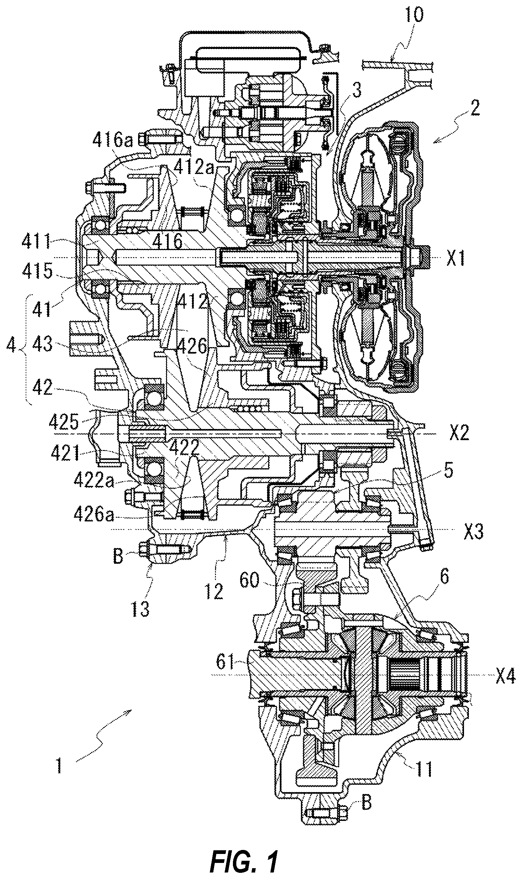
is a diagram illustrating a continuously variable transmission 1 .
In the continuously variable transmission 1 , a rotational driving force of an engine (not illustrated) is input to a variator 4 via a torque converter 2 and a forward and reverse switching mechanism 3 . The rotational driving force is transmitted to a driving wheel (not illustrated) via a reduction gear 5 and a differential device 6 after being shifted by the variator 4 .
The variator 4 includes a pair of pulleys (a primary pulley 41 and a secondary pulley 42 ) and a chain 43 wound around the pair of pulleys. The chain 43 is an endless annular member in which a plurality of link plates (not illustrated) are coupled by rocker pins (not illustrated).
The primary pulley 41 and the secondary pulley 42 are provided rotatably about rotation axes X 1 and X 2 that are parallel to each other.
The primary pulley 41 includes a fixed pulley 411 , and a movable pulley 415 that can be displaced in a direction of the rotation axis X 1 .
The fixed pulley 411 and the movable pulley 415 respectively include sheave portions 412 and 416 both extending in a radial direction of the rotation axis X 1 . The sheave portions 412 and 416 respectively have sheave surfaces 412 a and 416 a facing each other. The sheave surfaces 412 a and 416 a are inclined with respect to the rotation axis X 1 .
In the primary pulley 41 , a V groove around which the chain 43 is wound is provided between the sheave surfaces 412 a and 416 a.
In the primary pulley 41 , a groove width of the V groove is changed by the displacement of the movable pulley 415 in the direction of the rotation axis X 1 , and a winding radius of the chain 43 in the primary pulley 41 is changed.
The secondary pulley 42 also includes a fixed pulley 421 , and a movable pulley 425 that can be displaced in a direction of the rotation axis X 2 .
The fixed pulley 421 and the movable pulley 425 respectively include sheave portions 422 and 426 each extending in a radial direction of the rotation axis X 2 . The sheave portions 422 and 426 respectively have sheave surfaces 422 a and 426 a facing each other. The sheave surfaces 422 a and 426 a are inclined with respect to the rotation axis X 2 .
In the secondary pulley 42 , a V groove around which the chain 43 is wound is provided between the sheave surfaces 422 a and 426 a.
In the secondary pulley 42 , a groove width of the V groove is changed by the displacement of the movable pulley 425 in the direction of the rotation axis X 2 , and a winding radius of the chain 43 in the secondary pulley 42 is changed.
The rotational driving force of the engine is input to the primary pulley 41 via the torque converter 2 and the forward and reverse switching mechanism 3 . The rotational driving force input to the primary pulley 41 is transmitted to the secondary pulley 42 via the chain 43 .
At this time, by changing the winding radii of the chain 43 in the primary pulley 41 and the secondary pulley 42 , the rotational driving force input to the primary pulley 41 is shifted and transmitted to the secondary pulley 42 .
The rotational driving force transmitted to the secondary pulley 42 is transmitted to the reduction gear 5 . The reduction gear 5 is provided rotatably about a rotation axis X 3 parallel to the rotation axis X 2 . A final gear 60 of the differential device 6 meshes with the reduction gear 5 so as to transmit rotation.
Accordingly, the rotational driving force transmitted from the secondary pulley 42 to the reduction gear 5 is transmitted to the differential device 6 via the final gear 60 . Then, a drive shaft 61 coupled to the differential device 6 rotates about a rotation axis X 4 parallel to the rotation axis X 3 . Then, a drive wheel (not illustrated) to which the drive shaft 61 is coupled is rotated by the transmitted rotational driving force.
The torque converter 2 , the forward and reverse switching mechanism 3 , the variator 4 , the reduction gear 5 , and the differential device 6 are accommodated in a transmission case 10 (see ).
The transmission case 10 includes a converter housing 11 , a case 12 , and a side cover 13 . The converter housing 11 , the case 12 , and the side cover 13 are stacked in order in the direction of the rotation axis X 1 .
As illustrated in , the converter housing 11 accommodates the torque converter 2 . The converter housing 11 is attached to an engine block (not illustrated) in the direction of the rotation axis X 1 . The converter housing 11 and the engine block are fixed by a bolt (not illustrated).
The case 12 accommodates the forward and reverse switching mechanism 3 , the variator 4 , the reduction gear 5 , and the differential device 6 . The case 12 is attached to the converter housing 11 in the direction of the rotation axis X 1 . The case 12 and the converter housing 11 are fixed by a bolt B.
The side cover 13 is attached to the case 12 in the direction of the rotation axis X 1 . The side cover 13 and the case 12 are fixed by the bolt B.
is a perspective view of the case 12 as viewed from a side cover 13 side.
is a front view of the case 12 as viewed from the side cover 13 side.
is a front view of the case 12 as viewed from a converter housing 11 side.
In , the variator 4 is indicated by imaginary lines. In , the forward and reverse switching mechanism 3 , the reduction gear 5 , and the final gear 60 are indicated by imaginary lines.
In , in order to facilitate understanding of a position of a joining surface with the side cover 13 , the joining surface is hatched. In , in order to facilitate understanding of a joining surface with the converter housing 11 and positions of arc-shaped walls 123 and 124 , the joining surface and the arc-shaped walls 123 and 124 are hatched.
As illustrated in , the case 12 includes an intermediate wall portion 125 . The intermediate wall portion 125 is formed in an internal space of the case 12 . The intermediate wall portion 125 is formed in an orientation intersecting the rotation axes X 1 and X 2 . The internal space of the case 12 is divided into a space S 1 (see ) and a space S 2 (see ) by the intermediate wall portion 125 . The space S 1 is located on one side (the side cover 13 side) of the intermediate wall portion 125 in the direction of the rotation axes X 1 and X 2 , and the space S 2 is located on the other side (the converter housing 11 side).
As illustrated in , the space S 1 is a space in a recess formed by surrounding the intermediate wall portion 125 with an annular wall 121 . As illustrated in , the space S 2 is a space in a recess formed by surrounding the intermediate wall portion 125 with an annular wall 122 . The annular wall 121 and the annular wall 122 extend in directions away from each other from the intermediate wall portion 125 (a front-rear direction in the paper in ).
The variator 4 is accommodated in the space S 1 of the case 12 (see the imaginary lines in ). The forward and reverse switching mechanism 3 , the reduction gear 5 , and the differential device 6 (final gear 60 ) are accommodated in the space S 2 of the case 12 (see the imaginary lines in ).
As illustrated in , through holes 125 a and 125 b are formed in the intermediate wall portion 125 of the case 12 . The through holes 125 a and 125 b are formed in a region intersecting the rotation axes X 1 and X 2 of the primary pulley 41 and the secondary pulley 42 . The space S 1 and the space S 2 communicate with each other via the through holes 125 a and 125 b.
As illustrated in , a through hole 125 c is formed in the intermediate wall portion 125 of the case 12 . The through hole 125 c is formed in a region intersecting the rotation axis X 4 of the final gear 60 . The space S 2 also communicates with a region outside the annular wall 121 (a region outside the space S 1 ) through the through hole 125 c (see ).
As illustrated in , on a space S 2 side of the intermediate wall portion 125 , the arc-shaped wall 123 surrounding the through hole 125 a and the arc-shaped wall 124 surrounding the through hole 125 c are formed. A region surrounded by the arc-shaped wall 123 in the space S 2 constitutes an accommodation chamber R 1 accommodating the forward and reverse switching mechanism 3 . A region surrounded by the arc-shaped wall 124 in the space S 2 constitutes a differential chamber R 2 accommodating the final gear 60 .
As illustrated in , the variator 4 is accommodated in the space S 1 of the case 12 . The chain 43 is wound around the primary pulley 41 and the secondary pulley 42 in the space S 1 .
In a region between the primary pulley 41 and the secondary pulley 42 , the chain 43 tends to vibrate because the chain 43 is not in contact with the sheave surfaces 412 a and 416 a (see ) or the sheave surfaces 422 a and 426 a (see ). Therefore, the continuously variable transmission 1 includes chain guides 9 A and 9 B (see ) for reducing the vibration of the chain 43 .
is a diagram illustrating an arrangement of the chain guides 9 A and 9 B in the variator 4 .
corresponds to the variator 4 indicated by the imaginary lines in . In addition, in , for convenience of description, the chain guide 9 A is illustrated in a schematic view of a cross section thereof, and the chain guide 9 B is illustrated in a side view. Further, the chain 43 is illustrated in a simplified manner.
As illustrated in , the chain guides 9 A and 9 B are arranged in a region in which the chain 43 is not wound around the primary pulley 41 and the secondary pulley 42 .
The chain guides 9 A and 9 B are arranged in a symmetrical positional relationship with respect to a straight line Lm 1 . The straight line Lm 1 is a line connecting the rotation axis X 1 of the primary pulley 41 and the rotation axis X 2 of the secondary pulley 42 .
The chain guide 9 A and the chain guide 9 B are respectively disposed on an upper side and a lower side of the straight line Lm 1 in a direction of a vertical line VL. The vertical line VL is a line based on a state where the continuously variable transmission 1 is mounted on the vehicle.
As illustrated in , the chain guide 9 A is swingably coupled to a chain guide support shaft 7 A. The chain guide 9 B is swingably coupled to a chain guide support shaft 7 B. The chain guide support shafts 7 A and 7 B are arranged in a symmetrical positional relationship with respect to the straight line Lm 1 .
When viewed from the direction of the rotation axes X 1 and X 2 , the chain guide support shafts 7 A and 7 B are arranged on an inner side of the chain 43 . The chain guide support shafts 7 A and 7 B are supported by tubular members 8 A and 8 B, respectively, which will be described later.
The chain guides 9 A and 9 B according to the present embodiment have the same shape. In the following description, the chain guide 9 B will be described as an example. Description of the chain guide 9 A will be omitted.
is a diagram illustrating the chain guide 9 B and is a perspective view of the chain guide 9 B as viewed from an intermediate wall portion 125 side. In , a tubular member 8 B is separated from the chain guide support shaft 7 B.
is a perspective view illustrating the tubular member 8 B.
is a diagram illustrating the tubular member 8 B and is a schematic view of a cross section obtained by cutting the tubular member 8 B of along a longitudinal direction thereof.
A are diagrams illustrating the tubular member 8 B and is a schematic view of an A-A cross section in .
is a diagram illustrating an arrangement of the tubular members 8 A and 8 B in the space S 1 and is a schematic view of an A-A cross section in .
As illustrated in , the chain guide 9 B includes a pair of guide members 91 R and 91 L. The guide members 91 R and 91 L have the same shape. The chain guide 9 B is formed with the guide members 91 R and 91 L overlapped in a direction of a straight line Lx 1 parallel to the rotation axes X 1 and X 2 .
The guide member 91 R includes guide portions 910 Ra and 910 Rb and a connection portion 911 R that connects the guide portions 910 Ra and 910 Rb to each other. The guide portions 910 Ra and 910 Rb are arranged on one side and the other side in a thickness direction (an up-down direction in ) of the chain 43 . The connection portion 911 R is disposed on a lateral side (a right side in ) of the chain 43 .
The guide portions 910 Ra and 910 Rb and the connection portion 911 R of the guide member 91 R are integrally formed of the same material. The guide portions 910 Ra and 910 Rb are plate-shaped members arranged along a longitudinal direction of the chain 43 . The connection portion 911 R connects central portions of the guide portions 910 Ra and 910 Rb in a longitudinal direction to each other.
The guide member 91 L includes guide portions 910 La and 910 Lb and a connection portion 911 L that connects the guide portions 910 La and 910 Lb to each other. The guide portions 910 La and 910 Lb are arranged on one side and the other side in the thickness direction (the up-down direction in ) of the chain 43 . The connection portion 911 L is disposed on a lateral side (a left side in ) of the chain 43 .
The guide portions 910 La and 910 Lb and the connection portion 911 L of the guide member 91 L are integrally formed of the same material. The guide portions 910 La and 910 Lb are plate-shaped members arranged along the longitudinal direction of the chain 43 . The connection portion 911 L connects central portions of the guide portions 910 La and 910 Lb in a longitudinal direction to each other.
The guide members 91 R and 91 L are overlapped with each other in the direction of the straight line Lx 1 . The guide portions 910 Ra and 910 La are in contact with each other and the guide portions 910 Rb and 910 Lb are in contact with each other over an entire length of the chain 43 in the longitudinal direction thereof.
The chain 43 is disposed in a space surrounded by the guide portions 910 Ra and 910 Rb and the connection portion 911 R of the guide member 91 R and the guide portions 910 La and 910 Lb and the connection portion 911 L of the guide member 91 L.
Here, the guide members 91 R and 91 L respectively include coupling portions 912 R and 912 L coupled to the chain guide support shaft 7 B. The coupling portions 912 R and 912 L are also integrally formed with the guide portions 910 Ra and 910 La, respectively.
The coupling portions 912 R and 912 L are respectively formed at central portions of the guide portions 910 Ra and 910 La in the longitudinal direction thereof. The coupling portions 912 R and 912 L are overlapped with each other in the direction of the straight line Lx 1 and coupled by the bolts B. Accordingly, the guide members 91 R and 91 L are maintained in a state of being overlapped with each other in the direction of the straight line Lx 1 .
[Chain Guide Support Shaft 7 B]
As illustrated in , the chain guide support shaft 7 B is a shaft-shaped member disposed in an orientation along an axis line Lx 2 parallel to the rotation axes X 1 and X 2 . The chain guide support shaft 7 B includes a small-diameter shaft portion 70 and a large-diameter shaft portion 71 .
As illustrated in , in the chain guide support shaft 7 B, the small-diameter shaft portion 70 is one end 7 a side (a left side in the diagram) in a direction of the axis line Lx 2 , and the large-diameter shaft portion 71 is on the other end 7 b side (a right side in the diagram). A stepped surface 73 is formed at a boundary between the small-diameter shaft portion 70 and the large-diameter shaft portion 71 . The stepped surface 73 is a flat surface orthogonal to the axis line Lx 2 .
The small-diameter shaft portion 70 of the chain guide support shaft 7 B is inserted into an insertion hole 131 of the side cover 13 from the direction of the axis line Lx 2 . The stepped surface 73 of the chain guide support shaft 7 B abuts on a peripheral edge portion 131 a of the insertion hole 131 from the direction of the axis line Lx 2 .
The large-diameter shaft portion 71 of the chain guide support shaft 7 B includes a flange-shaped support plate 711 . The support plate 711 is formed at an intermediate position of the large-diameter shaft portion 71 in the direction of the axis line Lx 2 . The intermediate position of the large-diameter shaft portion 71 is between one end and the other end of the large-diameter shaft portion 71 in the direction of the axis line Lx 2 .
The support plate 711 extends radially outward of the axis line Lx 2 from an outer periphery of the large-diameter shaft portion 71 . The support plate 711 surrounds the large-diameter shaft portion 71 over an entire circumference in a circumferential direction around the axis line Lx 2 (see ).
As illustrated in , an insertion hole 72 is opened in the other end 7 b of the chain guide support shaft 7 B. The insertion hole 72 extends in the direction of the axis line Lx 2 inside the large-diameter shaft portion 71 . The tubular member 8 B is inserted into the insertion hole 72 from the direction of the axis line Lx 2 (see ).
[Tubular Member 8 B]
As illustrated in , the tubular member 8 B is formed by bending one steel pipe at two locations between one end and the other end thereof in the longitudinal direction.
Specifically, as illustrated in , the tubular member 8 B includes a first tubular portion 80 disposed in the orientation along the axis line Lx 2 , and a second tubular portion 81 disposed in an orientation along an axis line Lx 3 . The axis line Lx 3 is parallel to the axis line Lx 2 . The first tubular portion 80 and the second tubular portion 81 are connected to each other via a tubular connection portion 82 . The first tubular portion 80 is located on one end 8 a side (a left side in the diagram) of the tubular member 8 B in the longitudinal direction, and the second tubular portion 81 is located on the other end 8 b side (a right side in the diagram).
As illustrated in , the first tubular portion 80 includes a bottom wall portion 802 orthogonal to the axis line Lx 2 , and a tubular wall portion 801 surrounding an entire outer periphery of the bottom wall portion 802 .
The tubular wall portion 801 extends from the bottom wall portion 802 to the other side (a right side in the diagram) in the direction of the axis line Lx 2 . The tubular wall portion 801 is connected to the connection portion 82 on the other side in the direction of the axis line Lx 2 .
The connection portion 82 is disposed in an orientation along an axis line La intersecting the axis line Lx 2 and the axis line Lx 3 . The connection portion 82 is connected to the second tubular portion 81 on a side opposite to the first tubular portion 80 in a direction of the axis line La.
The second tubular portion 81 includes a tubular wall portion 811 surrounding the axis line Lx 3 . The tubular wall portion 811 extends from the connection portion 82 to the other side (the right side in the diagram) in a direction of the axis line Lx 3 . The tubular wall portion 811 has an opening end 811 c at an end surface (the other end 8 b ) on the other side in the direction of the axis line Lx 3 .
The tubular member 8 B has a bottomed tubular shape as a whole. Internal spaces of the first tubular portion 80 , the connection portion 82 , and the second tubular portion 81 communicate with one another, and one oil passage 85 is formed inside the tubular member 8 B. One end of the oil passage 85 is sealed by the bottom wall portion 802 of the first tubular portion 80 . The other end of the oil passage 35 communicates with an outside through the opening end 811 c of the second tubular portion 81 .
As illustrated in , a flange-shaped support plate 803 is formed at the first tubular portion 80 of the tubular member 8 B. The support plate 803 is formed at an intermediate position of the tubular wall portion 801 in the direction of the axis line Lx 2 . The intermediate position of the tubular wall portion 801 is between one end and the other end of the tubular wall portion 801 in the direction of the axis line Lx 2 . The support plate 803 extends radially outward of the axis line Lx 2 from an outer periphery of the tubular wall portion 801 . The support plate 803 surrounds the tubular wall portion 801 over the entire circumference in the circumferential direction around the axis line Lx 2 (see ).
The support plate 803 includes an inner-diameter side region 803 a and an outer-diameter side region 803 b in a radial direction (the up-down direction in the diagram) of the axis line Lx 2 . The inner-diameter side region 803 a is offset to the other side (the right side in the diagram) in the direction of the axis line Lx 2 with respect to the outer-diameter side region 803 b . The support plate 803 includes a recess 803 c inside the outer-diameter side region 803 b in the radial direction of the axis line Lx 2 .
As illustrated in , the second tubular portion 81 includes a strip-shaped bracket 813 . The bracket 813 is formed at an intermediate position of the tubular wall portion 811 in the direction of the axis line Lx 3 . The intermediate position of the tubular wall portion 811 is between one end and the other end of the tubular wall portion 811 in the direction of the axis line Lx 3 . The bracket 813 is fixed to the tubular wall portion 811 with a thickness direction being along the direction of the axis line Lx 3 .
As illustrated in A , when viewed from the direction of the axis line Lx 3 , a straight line Lp along a longitudinal direction of the bracket 813 intersects the axis line Lx 2 and the axis line Lx 3 .
The tubular wall portion 811 is located on one side (an upper side in the diagram) of the bracket 813 in a direction of the straight line Lp. A through hole 813 a penetrating the bracket 813 in the thickness direction thereof is formed on the other side (a lower side in the diagram) of the bracket 813 in the direction of the straight line Lp.
As illustrated in , a through hole 815 penetrating the tubular wall portion 811 in the thickness direction thereof is formed in the tubular wall portion 811 of the second tubular portion 81 . The through hole 815 is located on the other end 8 b side of the tubular member 8 B. A distance between the through hole 815 and the bracket 813 in the direction of the axis line Lx 3 is set to T 1 .
As illustrated in A , the through hole 815 allows an outside of the tubular member 8 B to communicate with the oil passage 85 . In addition, when viewed from the direction of the axis line Lx 3 , the through hole 815 is displaced from the straight line Lp in a circumferential direction around the axis line Lx 3 . A straight line Lq that connects the through hole 815 and the axis line Lx 3 is inclined with respect to the straight line Lp along the longitudinal direction of the bracket 813 .
As illustrated in , the first tubular portion 80 of the tubular member 8 B is inserted into the insertion hole 72 of the chain guide support shaft 7 B from the direction of the axis line Lx 2 .
In addition, the second tubular portion 81 of the tubular member 8 B is inserted into an insertion hole 128 formed in the intermediate wall portion 125 . The second tubular portion 81 is inserted into the insertion hole 128 from the direction of the axis line Lx 3 . A boss portion 129 is formed on the intermediate wall portion 125 of the case 12 . The bracket 813 is fixed to the boss portion 129 with the bolt B from a direction of an axis line Lx 4 parallel to the axis line Lx 3 .
The insertion hole 128 and the boss portion 129 are formed below the straight line Lm 1 in the intermediate wall portion 125 (see A ).
In this state, the chain guide support shaft 7 B and the tubular member 8 B are attached across the side cover 13 and the case 12 . The chain guide support shaft 7 B and the tubular member 8 B cross the space S 1 in a direction along the axis line Lx 2 .
As illustrated in , the support plate 711 of the chain guide support shaft 7 B and the support plate 803 of the tubular member 8 B are spaced apart from each other in the direction of the axis line Lx 2 . The coupling portions 912 L and 912 R of the chain guide 9 B described above are arranged between the support plate 711 and the support plate 803 in the direction of the axis line Lx 2 .
Vibration of a chain 43 is finally dispersed to the case 12 and the side cover 13 through the chain guide support shaft 7 B and the tubular member 8 B after being received by the chain guide 9 B. Accordingly, the vibration of the chain 43 is reduced.
Here, as illustrated in , the first tubular portion 80 of the tubular member 8 B is inserted into the insertion hole 72 of the chain guide support shaft 7 B, and the recess 803 c of the support plate 803 accommodates the other end 7 b side of the chain guide support shaft 7 B. Accordingly, the tubular member 8 B supports the chain guide support shaft 7 B while preventing the chain guide support shaft 7 B itself from vibrating in the radial direction of the axis line Lx 2 due to the vibration of the chain 43 .
That is, in a relationship between the tubular member 8 B and the chain guide support shaft 7 B, the tubular member 8 B serves as a support member, and the chain guide support shaft 7 B serves as a supported member.
As illustrated in , the chain guide 9 A also includes the coupling portions 912 L and 912 R. The chain guide 9 A is coupled to the chain guide support shaft 7 A via the coupling portions 912 L and 912 R.
The chain guide support shaft 7 A is one shaft-shaped member and has the same basic shape as that of the chain guide support shaft 7 B described above.
Hereinafter, the chain guide support shaft 7 A will be described.
In the following description, a portion of the chain guide support shaft 7 A different from the chain guide support shaft 7 B will be described. The same portions as those of the chain guide support shaft 7 B will be described with the same reference numerals.
As illustrated in , the chain guide support shaft 7 A is disposed in an orientation along an axis line Lx 5 parallel to the rotation axes X 1 and X 2 (see ).
The chain guide support shaft 7 A includes the small-diameter shaft portion 70 and the large-diameter shaft portion 71 . The small-diameter shaft portion 70 is located on the one end 7 a side of the chain guide support shaft 7 A in a direction of the axis line Lx 5 , and the large-diameter shaft portion 71 is located on the other end 7 b side.
As illustrated in , the small-diameter shaft portion 70 of the chain guide support shaft 7 A is inserted into an insertion hole 132 of the side cover 13 from the direction of the axis line Lx 5 . The stepped surface 73 of the chain guide support shaft 7 A abuts on a peripheral edge portion 132 a of the insertion hole 132 from the direction of the axis line Lx 5 .
An oil passage 75 extending in the direction of the axis line Lx 5 is formed inside the chain guide support shaft 7 A. The oil passage 75 penetrates the small-diameter shaft portion 70 and the large-diameter shaft portion 71 in the direction of the axis line Lx 5 . The oil passage 75 is opened at one end 7 a and the other end 7 b of the chain guide support shaft 7 A.
As illustrated in , in the large-diameter shaft portion 71 , an injection hole 76 is formed in a region between the support plate 711 and the other end 7 b in the direction of the axis line Lx 5 . The injection hole 76 penetrates the large-diameter shaft portion 71 in a direction orthogonal to the axis line Lx 5 and allows the oil passage 75 to communicate with the space S 1 .
The tubular member 8 A is inserted into the oil passage 75 of the chain guide support shaft 7 A from the other end 7 b side.
The tubular member 8 A is formed by bending one steel pipe at two locations between one end and the other end thereof in the longitudinal direction and has the same basic shape as that of the tubular member 8 B described above.
Hereinafter, the tubular member 8 A will be described.
In the following description, a portion of the tubular member 8 A different from the tubular member 8 B will be described. The same portions as those of the tubular member 8 B will be described with the same reference numerals.
The tubular member 8 A is different from the tubular member 8 B in that the tubular member 8 A does not include the bottom wall portion 802 of the first tubular portion 80 and the oil passage 85 is opened at both ends in the longitudinal direction. In addition, the tubular member 8 A is different from the tubular member 8 B in that the tubular member 8 A does not include the through hole 815 in the second tubular portion 81 .
As illustrated in , in the tubular member 8 A, the first tubular portion 80 is inserted into the oil passage 75 of the chain guide support shaft 7 A from the direction of the axis line Lx 5 . In the tubular member 8 A, the second tubular portion 81 is inserted into an insertion hole 126 formed in the intermediate wall portion 125 . The second tubular portion 81 is inserted into the insertion hole 126 from a direction of an axis line Lx 6 parallel to the axis line Lx 5 . The bracket 813 is fixed to a boss portion 127 formed on the intermediate wall portion 125 of the case 12 with the bolt B. The insertion hole 126 and the boss portion 127 are formed above the straight line Lm 1 in the intermediate wall portion 125 (see ).
In this state, the chain guide support shaft 7 A and the tubular member 8 A are attached across the side cover 13 and the case 12 . The chain guide support shaft 7 A and the tubular member 8 A cross the space S 1 in a direction along the axis line Lx 5 .
Here, as illustrated in , the insertion hole 126 into which the second tubular portion 81 of the tubular member 8 A is inserted communicates with an in-case oil passage 15 in the intermediate wall portion 125 . In addition, the insertion hole 128 into which the second tubular portion 81 of the tubular member 8 B is inserted communicates with an in-case oil passage 16 in the intermediate wall portion 125 .
The in-case oil passages 15 and 16 are lubricating oil passages for supplying lubricating oil OL in the case 12 , which is raised by the rotation of the final gear 60 (see ), to a predetermined region in the case 12 .
[In-Case Oil Passage 15 ]
As illustrated in , the in-case oil passage 15 extends in the direction of the axis line Lx 6 in the intermediate wall portion 125 . The other end 15 b of the in-case oil passage 15 in the direction of the axis line Lx 6 is opened in the arc-shaped wall 123 (see ) in the space S 2 side described above. The insertion hole 126 is connected to one end 15 a of the in-case oil passage 15 in the direction of the axis line Lx 6 .
The insertion hole 126 extends in the direction of the axis line Lx 6 . An end portion of the insertion hole 126 on a side (a space S 1 side) opposite to the in-case oil passage 15 in the direction of the axis line Lx 6 is opened in a surface of the intermediate wall portion 125 (see ). The in-case oil passage 15 communicates with the space S 1 via the insertion hole 126 . The insertion hole 126 constitutes a part of the in-case oil passage 15 .
The first tubular portion 80 of the tubular member 8 A is inserted into the oil passage 75 in the chain guide support shaft 7 A, and the second tubular portion 81 is inserted into the insertion hole 126 . Accordingly, the oil passage 85 in the tubular member 8 A communicates with the oil passage 75 of the chain guide support shaft 7 A on a first tubular portion 80 side and communicates with the in-case oil passage 15 on a second tubular portion 81 side.
An oil passage 135 formed in the side cover 13 communicates with the insertion hole 132 of the side cover 13 into which the small-diameter shaft portion 70 of the chain guide support shaft 7 A is inserted.
Therefore, the in-case oil passage 15 communicates with the oil passage 135 of the side cover 13 via the oil passage 85 in the tubular member 8 A and the oil passage 75 in the chain guide support shaft 7 A.
Accordingly, a part of the lubricating oil OL that is raised by the rotation of the final gear 60 flows from the other end 15 b (see ) of the in-case oil passage 15 and is supplied from the one end 15 a to the oil passage 85 in the tubular member 8 A. Then, the lubricating oil OL supplied to the oil passage 85 finally moves to the oil passage 135 in the side cover 13 through the oil passage 75 in the chain guide support shaft 7 A. A part of the lubricating oil OL passing through the oil passage 75 is injected from the injection hole 76 to lubricate the chain 43 .
[In-Case Oil Passage 16 ]
The in-case oil passage 16 is formed in a rib 18 (see ) provided on the intermediate wall portion 125 . The rib 18 protrudes from the intermediate wall portion 125 to the space S 1 side (a front side in the paper in ) in the direction of the rotation axes X 1 and X 2 .
A are diagrams illustrating the rib 18 and is an enlarged view of a region A in .
is a diagram illustrating the in-case oil passage 16 formed in the rib 18 and is a schematic view of an A-A cross section in A .
is a diagram illustrating an arrangement of the tubular member 8 B.
In , the tubular member 8 B is indicated by imaginary lines. In addition, in , the final gear 60 in the differential chamber R 2 is omitted.
As illustrated in , the rib 18 protrudes from the intermediate wall portion 125 to the front side in the paper. The rib 18 is located below the straight line Lm 1 connecting the rotation axis X 1 and the rotation axis X 2 . The rib 18 is provided in an orientation along a straight line Lr. The straight line Lr is a line substantially parallel to a straight line Lm 2 connecting the rotation axis X 1 and the rotation axis X 4 . The rib 18 crosses the annular wall 121 from an inner side to an outer side. One end portion 18 a (a left side in the diagram) of the rib 18 in a direction of the straight line Lr is located in the space S 1 and is located in a vicinity of the through hole 125 a . The other end 18 b (a right side in the diagram) of the rib 18 in the direction of the straight line Lr is located outside the space S 1 and is located in a vicinity of the through hole 125 c.
The insertion hole 128 and the boss portion 129 described above are formed on one end portion 18 a side (the left side in the diagram) of the rib 18 . The insertion hole 128 is located on the straight line Lr. The boss portion 129 is located below the straight line Lr on the other end 18 b side of the rib 18 when viewed from the insertion hole 128 .
As illustrated in , the in-case oil passage 16 is formed in the rib 18 .
When viewed from the direction of the rotation axis X 4 , the in-case oil passage 16 extends in a radial direction of the rotation axis X 4 in a region overlapping the differential chamber R 2 . In , a position of the in-case oil passage 16 is indicated by a broken line.
As illustrated in , the in-case oil passage 16 includes an outer-diameter side oil passage 161 , an inner-diameter side oil passage 162 , and a connection oil passage 163 .
The outer-diameter side oil passage 161 is provided in an orientation along the rotation axis X 4 . One end 161 a of the outer-diameter side oil passage 161 communicates with the insertion hole 128 . The other end 161 b of the outer-diameter side oil passage 161 is opened in the arc-shaped wall 123 described above (see ).
The insertion hole 128 communicating with the one end 161 a of the outer-diameter side oil passage 161 is provided in series with the outer-diameter side oil passage 161 in the orientation along the rotation axis X 4 . The insertion hole 128 and the outer-diameter side oil passage 161 are concentrically arranged.
An end portion of the insertion hole 128 on a side opposite to the outer-diameter side oil passage 161 in the direction of the rotation axis X 4 (a lower side in ) is opened in the surface of the intermediate wall portion 125 (the rib 18 ). The outer-diameter side oil passage 161 of the in-case oil passage 16 communicates with the space S 1 via the insertion hole 128 . The insertion hole 128 constitutes a part of the in-case oil passage 16 .
One end 163 a of the connection oil passage 163 is opened at an intermediate position of the insertion hole 128 in the direction of the rotation axis X 4 . The intermediate position of the insertion hole 128 is between one end and the other end of the insertion hole 128 in the direction of the rotation axis X 4 .
The connection oil passage 163 extends in the rib 18 in the direction of the straight line Lr (a left-right direction in ). The other end 163 b of the connection oil passage 163 opens toward an outside of the annular wall 121 . An opening of the other end 163 b is sealed with a plug Hs. Examples of the plug Hs include a known hollow set.
One end 162 a of the inner-diameter side oil passage 162 is opened on the other end 163 b side of the connection oil passage 163 .
The inner-diameter side oil passage 162 is located radially inward of the outer-diameter side oil passage 161 in the radial direction of the rotation axis X 4 . The inner-diameter side oil passage 162 extends in the direction of the rotation axis X 4 , and the other end 162 b is opened to the differential chamber R 2 (see ).
Here, as illustrated in an enlarged region in A , a straight line Ls connecting the insertion hole 128 and the boss portion 129 is inclined with respect to the straight line Lr.
The inclination of the straight line Lr with respect to the straight line Ls is the same as the inclination (see ) of the straight line Lq with respect to the straight line Lp in the bracket 813 of the tubular member 8 B described above.
In addition, as illustrated in , a distance between a surface of the rib 18 and the straight line Lr in the direction of the rotation axis X 4 is set to T 2 . The distance T 2 is the same as the distance T 1 (see ) between the bracket 813 of the tubular member 8 B and the through hole 815 described above (T 2 =T 1 ).
As illustrated in , the second tubular portion 81 of the tubular member 8 B is inserted into the insertion hole 128 . The oil passage 85 in the tubular member 8 B communicates with the outer-diameter side oil passage 161 via the opening end 811 c.
Then, as illustrated in the enlarged region of FIG. [ 11 ] 11 A, in a state where the second tubular portion 81 is inserted into the insertion hole 128 , the bracket 813 is fixed to the boss portion 129 . The straight line Lp (see ) along the longitudinal direction of the bracket 813 is disposed at a position that coincides with the straight line Ls connecting the insertion hole 128 and the boss portion 129 .
In this state, the straight line Lq (see ) connecting a center of the second tubular portion 81 and the through hole 815 coincides with the straight line Lr passing through a center of the connection oil passage 163 .
Accordingly, the internal space of the second tubular portion 81 communicates with the connection oil passage 163 via the through hole 815 . Therefore, the oil passage 85 in the tubular member 8 B communicates with the connection oil passage 163 via the through hole 815 (see the enlarged region in ).
As described above, the insertion hole 128 constitutes a part of the in-case oil passage 16 . Therefore, by inserting the tubular member 8 B into the insertion hole 128 , the oil passage 85 in the tubular member 8 B also constitutes a part of the in-case oil passage 16 . The oil passage 85 serves as an oil passage interposed between the outer-diameter side oil passage 161 and the connection oil passage 163 (see ).
A part of the lubricating oil OL that is raised by the rotation of the final gear 60 flows from the other end 161 b (see ) of the outer-diameter side oil passage 161 , and moves from an one end 161 a side into the oil passage 85 in the tubular member 8 B (an arrow A in ).
One end (a lower side in ) of the oil passage 85 is sealed by the bottom wall portion 802 . Then, the lubricating oil OL sequentially flows into the oil passage 85 from an opening end 811 c side. Therefore, an inside of the oil passage 85 is finally filled with the lubricating oil OL.
When the oil passage 85 is filled with the lubricating oil OL and the lubricating oil OL further flows into the oil passage 85 from the opening end 811 c side, a pressure in the oil passage 85 increases. The lubricating oil OL is discharged from the through hole 815 to the connection oil passage 163 . Accordingly, a flow of the lubricating oil OL that flows from the outer-diameter side oil passage 161 to the connection oil passage 163 through the oil passage 85 is formed (an arrow B in ).
The lubricating oil OL moved from the through hole 815 to the connection oil passage 163 moves from one end 163 a side to the other end 163 b side through the connection oil passage 163 (an arrow C in ).
The other end 163 b of the connection oil passage 163 is sealed with the plug Hs. Therefore, an orientation of the lubricating oil OL that moves through the connection oil passage 163 is changed by the plug Hs, and the lubricating oil OL moves from the one end 162 a to the inside of the inner-diameter side oil passage 162 .
The lubricating oil OL passing through the inner-diameter side oil passage 162 is returned from the other end 162 b to the differential chamber R 2 (an arrow D in ). The lubricating oil OL returned to the differential chamber R 2 is again raised by the rotation of the final gear 60 (see ).
Here, the case 12 is manufactured by casting. Although not illustrated, the in-case oil passages 15 and 16 in the case 12 are formed by placing cores at predetermined positions in a mold at the time of casting the case 12 and then pouring and solidifying molten metal. The cores have shapes corresponding to the in-case oil passages 15 and 16 .
In order to maintain attitudes of the cores in the mold, a part of the cores is abutted on the mold. Therefore, in the case 12 after solidification, portions where the cores and the mold are abutted appear as opening portions of the in-case oil passages 15 and 16 .
As illustrated in A , in the present embodiment, the insertion holes 126 and 128 and the other end 163 b side (see ) of the connection oil passage 163 correspond to the opening portions of the in-case oil passages 15 and 16 .
The in-case oil passage 15 is used to supply the lubricating oil OL to a variator 4 side. Therefore, the insertion hole 126 serving as the opening portion of the in-case oil passage 15 is used in an open state.
On the other hand, the in-case oil passage 16 is used to return the lubricating oil OL to the differential chamber R 2 . In order to reliably return the lubricating oil OL to the differential chamber R 2 , the insertion hole 128 serving as the opening portion of the in-case oil passage 16 and the other end 163 b side of the connection oil passage 163 are sealed with a sealing member.
As illustrated in , the tubular member 8 B is inserted into the insertion hole 128 . The plug Hs is inserted into the other end 163 b of the connection oil passage 163 . In the present embodiment, each of the tubular member 8 B and the plug Hs corresponds to the sealing member.
For example, when the tubular member 8 B is attached to a place other than the insertion hole 128 in the case 12 , a plug for sealing the insertion hole 128 is separately prepared. Then, the number of plugs (the number of components) to be used increases.
On the other hand, the tubular member 8 B according to the present embodiment is inserted into the insertion hole 128 in the case 12 (see ). Accordingly, the tubular member 8 B supports the chain guide support shaft 7 B and blocks the communication between the in-case oil passage 16 and the space S 1 implemented via the insertion hole 128 .
That is, the tubular member 8 B serves both as a support member and a plug. The plug for sealing the insertion hole 128 may not be separately used.
Even if a solid shaft member not including the oil passage 85 and the through hole 815 is used instead of the tubular member 8 B, the shaft member can both serve as the support member for the chain guide support shaft 7 B and the plug for the insertion hole 128 . However, when the shaft member is inserted into the insertion hole 128 , the flow of the lubricating oil OL from the outer-diameter side oil passage 161 to the connection oil passage 163 may be hindered. In this case, it is also conceivable to shallowly insert the shaft member into the insertion hole 128 such that the lubricating oil OL can flow. However, a support strength for supporting the chain guide support shaft 7 B is reduced.
The tubular member 8 B according to the present embodiment is a hollow steel pipe and includes the oil passage 85 and the through hole 815 . In the tubular member 8 B, the oil passage 85 and the through hole 815 constitute a part of the in-case oil passage 16 . Therefore, even if the tubular member 8 B is deeply inserted into the insertion hole 128 , the flow of the lubricating oil OL in the in-case oil passage 16 is not hindered. Accordingly, the support strength for supporting the chain guide support shaft 7 B can be improved.
An example of the continuously variable transmission 1 (the hydraulic actuation device) according to an aspect of the invention will be listed below.
•
• (1) The continuously variable transmission 1 includes: • the case 12 ; • the in-case oil passage 16 (an oil passage) provided in the case 12 ; and • the tubular member 8 B (a support member) that is provided in the case 12 and supports the chain guide support shaft 7 B (a supported member).
The in-case oil passage 16 includes the insertion hole 128 (an opening portion) that allows the in-case oil passage 16 to communicate with the space S 1 inside the case 12 .
The tubular member 8 B is inserted into the insertion hole 128 .
The communication between the in-case oil passage 16 and the space S 1 inside the case 12 is blocked by the tubular member 8 B.
When configured as described above, the tubular member 8 B can seal the insertion hole 128 while supporting the chain guide support shaft 7 B.
Accordingly, it is not necessary to use the support member for supporting the chain guide support shaft 7 B and the plug for sealing the insertion hole 128 , thereby reducing the number of components.
•
• (2) The tubular member 8 B inserts the second tubular portion 81 into the insertion hole 128 from the direction of the axis line Lx 3 . The tubular member 8 B is fixed to the case 12 in a state where a tightening force (a pressing force) of the bolt B (a fastening member) is applied along the direction of the axis line Lx 4 parallel to the direction of the axis line Lx 3 (an insertion direction).
The tubular member 8 B receives a pressure from the lubricating oil OL that flows into the oil passage 85 from the outer-diameter side oil passage 161 of the in-case oil passage 16 . This pressure acts in a direction in which the tubular member 8 B is pulled out from the insertion hole 128 (downward in ).
Therefore, when configured as described above, the fastening force of the bolt B applied to the tubular member 8 B is in a direction against the pressure received from the lubricating oil OL.
Accordingly, the tubular member 8 B is prevented from being pulled out from the insertion hole 128 , and sealing performance of the insertion hole 128 by the tubular member 8 B can be improved.
•
• (3) The in-case oil passage 16 is a lubricating oil passage for supplying the lubricating oil OL to the differential chamber R 2 .
The insertion hole 128 provided in the in-case oil passage 16 is sealed by the tubular member 8 B.
When the insertion hole 128 is opened on the space S 1 side, a part of the lubricating oil OL in the in-case oil passage 16 leaks to the space S 1 side. Then, an amount of the lubricating oil OL returned to the differential chamber R 2 decreases. In addition, when the insertion hole 128 is sealed with a separate plug, the number of components increases.
Therefore, by configuring as described above, the increase in the number of components can be reduced while reliably returning the lubricating oil OL, which is raised by the rotation of the final gear 60 , to the differential chamber R 2 .
•
• (4) The continuously variable transmission 1 includes: • the primary pulley 41 and the secondary pulley 42 that constitute a pair of pulleys; and • the chain 43 (an endless annular member) wound around the primary pulley 41 and the secondary pulley 42 .
The chain guide 9 B coupled to the chain guide support shaft 7 B is a guide member that guides the chain 43 .
The tubular member 8 B supports the chain guide support shaft 7 B coupled to the chain guide 9 B.
When configured as described above, in the chain continuously variable transmission 1 , the number of components to be used can be reduced.
•
• (5) The tubular member 8 B has a bottomed tubular shape, and includes the bottom wall portion 802 , the first tubular portion 80 surrounding the bottom wall portion 802 , the connection portion 82 , and the second tubular portion 81 .
In the tubular member 8 B, the through hole 815 penetrating the tubular wall portion 811 is formed in the tubular wall portion 811 (a side wall) of the second tubular portion 81 .
The tubular member 8 B is inserted into the insertion hole 128 from the opening end 811 c side of the second tubular portion 81 , and the through hole 815 communicates with the connection oil passage 163 of the in-case oil passage 16 .
The lubricating oil OL in the in-case oil passage 16 flows into the oil passage 85 (an internal space) of the tubular member 8 B from the outer-diameter side oil passage 161 through the opening end 811 c , and then is discharged from the through hole 815 to the connection oil passage 163 .
When configured as described above, the oil passage 85 in the tubular member 8 B serves as a part of the in-case oil passage 16 . Accordingly, the flow of the lubricating oil OL in the in-case oil passage 16 can be smoothly changed.
In addition, even if the tubular member 8 is deeply inserted into the insertion hole 128 , the flow of the lubricating oil OL is not hindered. Accordingly, the support strength for supporting the chain guide support shaft 7 B can be improved.
In a support structure 100 in the case 12 (see ) for the tubular member 8 B, one tubular member 8 B can support the chain guide support shaft 7 B and seal the insertion hole 128 .
The support structure 100 of the tubular member 8 B includes:
•
• the case 12 ; • the in-case oil passage 16 provided in the case 12 ; and • the tubular member 8 B that is provided in the case 12 and supports the chain guide support shaft 7 B.
The in-case oil passage 16 includes the insertion hole 128 that allows the in-case oil passage 16 to communicate with the space S 1 inside the case 12 .
The tubular member 8 B is inserted into the insertion hole 128 .
The tubular member 8 B is supported by the case 12 while blocking the communication between the in-case oil passage 16 and the space S 1 inside the case 12 .
When configured as described above, the tubular member 8 B can seal the insertion hole 128 while supporting the chain guide support shaft 7 B.
Accordingly, it is not necessary to use the support member for supporting the chain guide support shaft 7 B and the plug for sealing the insertion hole 128 , thereby reducing the number of components.
In the continuously variable transmission 1 according to the present embodiment, a case in which the opening end 811 c of the tubular member 8 B communicates with the outer-diameter side oil passage 161 of the in-case oil passage 16 , and the through hole 815 communicates with the connection oil passage 163 is exemplified, but the invention is not limited to the aspect. For example, the following modification may be made.
is a diagram illustrating a continuously variable transmission 1 A according to a modification.
In the continuously variable transmission 1 A according to the modification, only a portion different from the continuously variable transmission 1 according to the present embodiment will be described.
As illustrated in , in the continuously variable transmission 1 A, an insertion hole 128 A extends in a direction of a straight line Lr′ orthogonal to the axis line Lx 2 and is connected in series with a connection oil passage 163 ′. The outer-diameter side oil passage 161 is connected to an intermediate position of the insertion hole 128 A in the direction of the straight line Lr′. The intermediate position of the insertion hole 128 A is between one end and the other end of the insertion hole 128 A in the direction of the straight line Lr′.
A tubular member 8 B′ is formed by bending one steel pipe at one location between one end and the other end in a longitudinal direction thereof and has a substantially L-shape.
Specifically, the tubular member 8 B′ includes the first tubular portion 80 disposed in the orientation along the straight line Lx 2 , and a second tubular portion 81 ′ disposed in an orientation along the straight line Lr′.
When the second tubular portion 81 ′ of the tubular member 8 B′ is inserted into the insertion hole 128 A, the through hole 815 communicates with the outer-diameter side oil passage 161 of the in-case oil passage 16 , and the opening end 811 c communicates with the connection oil passage 163 ′.
In the continuously variable transmission 1 A according to the modification, the lubricating oil OL flows into the oil passage 85 in the tubular member 8 B′ from the outer-diameter side oil passage 161 through the through hole 815 . The lubricating oil OL is discharged from the opening end 811 c to the connection oil passage 163 ′. Then, the lubricating oil OL is discharged from the connection oil passage 163 ′ to the differential chamber R 2 through the inner-diameter side oil passage 162 (see arrows E to H in ).
As an aspect of the invention, the continuously variable transmission 1 A has, for example, the following configuration.
•
• (5) The tubular member 8 B′ has a bottomed tubular shape.
In the tubular member 8 B′, the through hole 815 penetrating the tubular wall portion 811 is formed in the tubular wall portion 811 (a side wall) of the second tubular portion 81 ′.
The tubular member 8 B′ is inserted into the insertion hole 128 A from the opening end 811 c side of the second tubular portion 81 , and the through hole 815 communicates with the outer-diameter side oil passage 161 of the in-case oil passage 16 .
The lubricating oil OL in the in-case oil passage 16 flows into the oil passage 85 in the tubular member 8 B′ from the outer-diameter side oil passage 161 through the through hole 815 , and then is discharged from the opening end 811 c to the connection oil passage 163 ′.
When configured as described above, the oil passage 85 in the tubular member 8 B′ serves as a part of the in-case oil passage 16 . Accordingly, the flow of the lubricating oil OL in the in-case oil passage 16 can be smoothly changed.
In the present embodiment, the chain continuously variable transmission 1 in which the endless annular member is the chain 43 is exemplified, but the invention is not limited to the aspect. For example, a belt continuously variable transmission in which the endless annular member is a belt may be used. Examples of the belt include a belt in which a plurality of plate-shaped elements are stacked and annularly arranged. Specifically, the element includes slits on both sides. The belt is formed by binding each element by an annular ring having a slit inserted therethrough.
In the present embodiment, a case in which the hydraulic actuation device is a chain continuously variable transmission for a vehicle is exemplified, but the invention is not limited to the aspect. In a case of a hydraulic actuation device in which an oil passage is provided in a case, the hydraulic actuation device can also be applied to others in addition to the vehicle.
Although the embodiment of the invention has been described above, the above embodiment merely exemplifies one application example of the invention and does not intend to limit the technical scope of the invention to the specific configuration of the above embodiment. The embodiment can be changed as appropriate within the scope of the technical idea of the invention.
REFERENCE SIGNS LIST
•
• 1 continuously variable transmission (hydraulic actuation device) • 1 A continuously variable transmission (hydraulic actuation device) • 12 case • 128 insertion hole (opening portion) • 128 A insertion hole (opening portion) • 16 in-case oil passage • 41 primary pulley • 42 secondary pulley • 43 chain (endless annular member) • 7 B chain guide support shaft (supported member) • 8 B tubular member (support member) • 8 B′ tubular member (support member) • 9 B chain guide (guide member) • 802 bottom wall portion • 811 tubular wall portion • 811 c opening end • 815 through hole • 85 oil passage (internal space) • B bolt (fastening member) • Lx 3 axis line (insertion direction) • OL lubricating oil • S 1 space
The present application claims a priority of Japanese Patent Application No. 2021-026686 filed with the Japan Patent Office on Feb. 22, 2021, all the contents of which are hereby incorporated by reference.
Figures (10)
Citations
This patent cites (5)
- US11466770
- US20110244999
- US20160201790
- US20200332883
- US2011-208796