Protector Structure for Electrical Component
Abstract
A protector structure for an inverter 1 which is an example of an electrical component includes a protector 3 including a protection portion 31 , an attachment portion 32 A and an attachment portion 32 B. The protector 3 has a constricted portion 33 A between the protection portion 31 and the attachment portion 32 A, and has a constricted portion 33 B between the protection portion 31 and the attachment portion 32 B.
Claims (7)
1. A protector structure for an electrical component that comprises a case, the protector structure comprising: a protector including: a protection portion configured to protect the electrical component from a collision of a colliding object, and a plurality of attachment portions attaching the protecting portion to the electrical component; wherein: each of the plurality of attachment portions comprises a contact portion coupled to the electrical component by a bolt, and in surface contact with the electrical component, the protection portion has a flat plate shape; one or more constricted portions between the protection portion and a respective attachment portion; wherein the one or more constricted portions have: a constriction with respect to the protection portion and the respective attachment portion, and a lower strength than the protection portion and the respective attachment portion.
Show 6 dependent claims
2. The protector structure for the electrical component according to claim 1 , wherein: a gravity center of the protector is disposed in a region surrounded by an outer edge of a region formed by connecting connection base portions of the protection portion with the plurality of the attachment portions.
3. The protector structure for the electrical component according to claim 1 , wherein: a region surrounded by an outer edge of a region formed by connecting connection base portions of the protection portion with the plurality of the attachment portions and a collision portion of the colliding object overlap each other when viewed along a vehicle front-rear direction.
4. The protector structure for the electrical component according to claim 1 , wherein: the case includes a receiving portion that is raised higher than a surrounding position at a portion where the protection portion faces.
5. The protector structure for the electrical component according to claim 4 , wherein: the receiving portion is formed of a rib having a mesh shape, and a size of a cell of the mesh shape is smaller than a size of a collision cross section of a collision portion of the colliding object.
6. The protector structure for the electrical component of claim 1 , wherein: at least one of the plurality of attachment portions is coupled directly to the protection portion without the one or more of the constriction portions therebetween.
7. The protector structure for the electrical component of claim 1 , wherein: each of the plurality of attachment portions is coupled to at least one of the one or more constriction portions.
Full Description
Show full text →
TECHNICAL FIELD
The present invention relates to a protector structure for an electrical component.
BACKGROUND ART
JP2014-076685A discloses a technique of attaching a protector to a presumable breakage portion as a countermeasure against breakage due to a collision.
SUMMARY OF INVENTION
The protector having high strength can prevent a load from being input to the presumable breakage portion at the time of a collision of a colliding object. However, the higher the strength of the protector, the smaller the possibility of deformation of the protector. As a result, in this case, the collision load is concentrated on an attachment portion of the protector, and a case of an electrical component may be broken at a portion where the attachment portion is provided.
The present invention has been made in view of such a problem, and an object thereof is to prevent breakage of a case of an electrical component due to a collision load via an attachment portion of a protector.
A protector structure for an electrical component according to one aspect of the present invention includes a protector including a protection portion configured to protect the electrical component from a collision of a colliding object, and an attachment portion to a member including a case of the electrical component. The protector includes a low-strength portion between the protection portion and the attachment portion, the low-strength portion having lower strength than the protection portion and the attachment portion.
BRIEF DESCRIPTION OF DRAWINGS
is a first external view of a protector structure for an inverter.
is a second external view of the protector structure for the inverter.
is a schematic plan view of the protector.
is a schematic side view of the protector.
is a first view illustrating arrangements of the protector and a colliding object.
is a second view illustrating the arrangements of the protector and the colliding object.
is a view illustrating a relationship between an arrangement of a gravity center of the protector and a predetermined region.
is a view illustrating a relationship between an arrangement of a protrusion and the predetermined region.
A is a first view of a first illustrative view of deformation of the protector.
B is a second view of the first illustrative view of the deformation of the protector.
A is a first view of a second illustrative view of the deformation of the protector.
B is a second view of the second illustrative view of the deformation of the protector.
C is a third view of the second illustrative view of the deformation of the protector.
A is a first view of a third illustrative view of the deformation of the protector.
B is a second view of the third illustrative view of the deformation of the protector.
C is a third view of the third illustrative view of the deformation of the protector.
is a view illustrating a first modification of the protector.
is a view illustrating a second modification of the protector.
is a view illustrating a third modification of the protector.
is a view illustrating a fourth modification of the protector.
is a view illustrating a fifth modification of the protector.
is a view illustrating a sixth modification of the protector.
is a view illustrating a seventh modification of the protector.
DESCRIPTION OF EMBODIMENTS
Hereinafter, an embodiment of the present invention will be described with reference to the accompanying drawings.
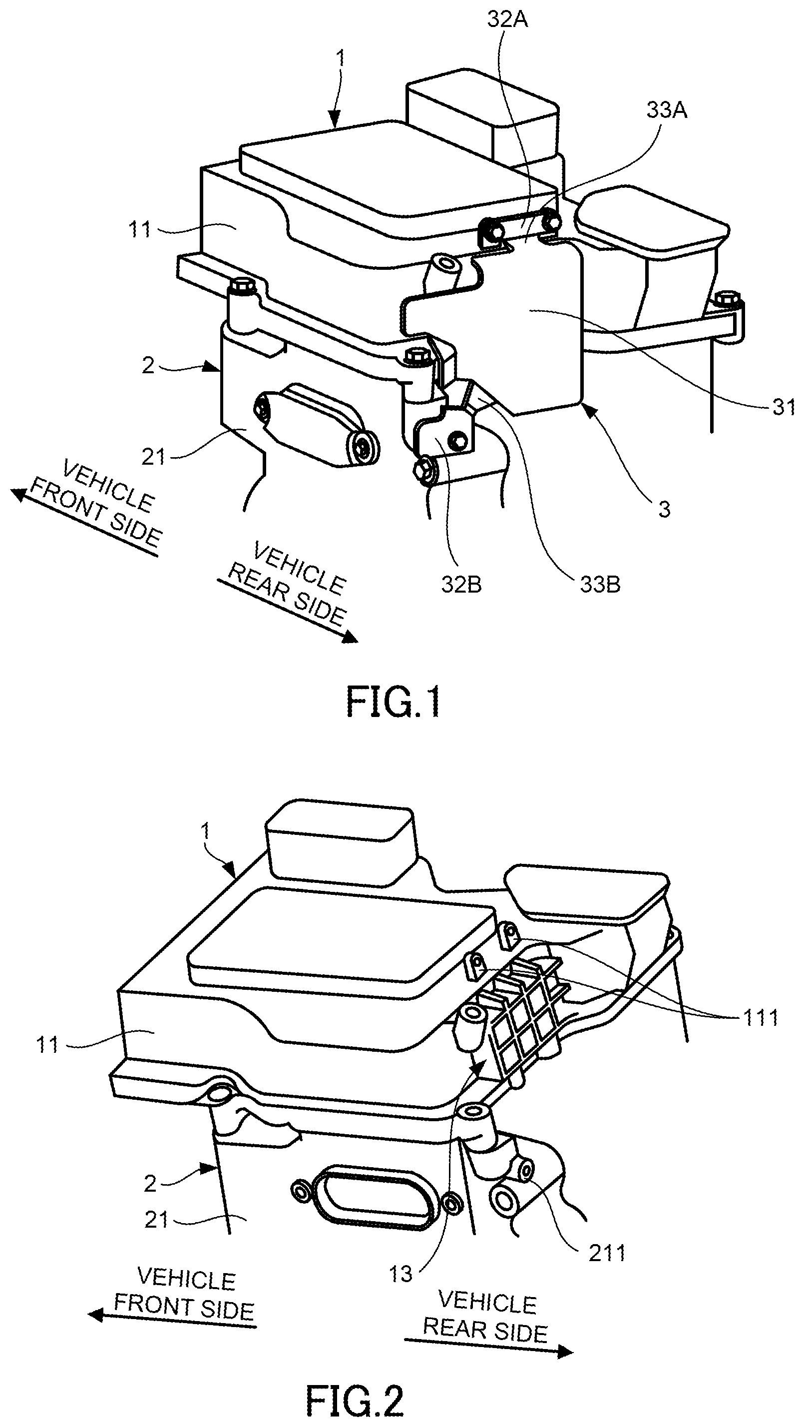
are external views of a protector structure for an inverter 1 . is a schematic plan view of a protector 3 . is a schematic side view of the protector 3 . shows the protector structure in a state where the protector 3 is removed.
The protector structure includes the inverter 1 , a motor 2 , and the protector 3 . The inverter 1 is an example of an electrical component and disposed above the motor 2 . A case 11 of the inverter 1 is fixed to a case 21 of the motor 2 by bolt fastening, and thus the inverter 1 and the motor 2 form an integrated structure.
The motor 2 constitutes a drive source of a vehicle. The motor 2 is housed in a motor room of the vehicle together with the inverter 1 . The vehicle is a series hybrid vehicle that travels by driving the motor 2 using electric power generated by a generator using power of an internal combustion engine.
The protector 3 is provided for the inverter 1 . The protector 3 is formed of a plate-shaped member and extends from the inverter 1 to the motor 2 . The protector 3 includes a protection portion 31 , an attachment portion 32 A, a constricted portion 33 A, an attachment portion 32 B, and a constricted portion 33 B.
The protection portion 31 protects the inverter 1 from a collision of a colliding object. The colliding object is a vehicle component disposed in the motor room, and is a master cylinder 4 to be described later in the present embodiment. The protection portion 31 has a flat plate shape and constitutes a protector surface of the protector 3 .
A receiving portion 13 that is raised higher than surrounding positions is provided at a portion of the case 11 where the protection portion 31 faces. The receiving portion 13 is a portion raised from a wall surface of the case 11 on which the receiving portion 13 is provided. The receiving portion 13 is formed of ribs having a mesh shape. The case 11 may not include the receiving portion 13 .
The attachment portion 32 A is attached to the case 11 . The attachment portion 32 A is in a state of being attached by bolts that are fixing members. As illustrated in , the attachment portion 32 A includes contact portions 321 A with the case 11 , and is attached in a state of surface contact with the case 11 at the contact portions 321 A.
The contact portions 321 A are formed around bolt holes, and are in surface contact with attachment portions 111 of the case 11 illustrated in . Two contact portions 321 A and two attachment portions 111 are provided.
The attachment portion 32 A configured as described above is attached to the case 11 in a state where at least a part of the attachment portion 32 A is in surface contact with the case 11 . Such an attachment portion 32 A is grasped as an attachment portion by interposing the constricted portion 33 A, which is a low-strength portion, between the protection portion 31 and the attachment portion 32 A.
The constricted portion 33 A is provided between the protection portion 31 and the attachment portion 32 A. The constricted portion 33 A has a constriction with respect to the protection portion 31 and the attachment portion 32 A. Therefore, strength of the constricted portion 33 A is lower than that in a case where the constricted portion 33 A has the same width as the narrower one of the protection portion 31 and the attachment portion 32 A, that is, in a case where the constricted portion 33 A is not constricted to any one of the protection portion 31 and the attachment portion 32 A. A width direction can be a direction orthogonal to a thickness direction of the protector 3 and an extending direction of the constricted portion 33 A.
In such a constricted portion 33 A, the strength against the collision of the colliding object with the protection portion 31 is lower than those of the protection portion 31 and the attachment portion 32 A. Therefore, when the colliding object collides with the protection portion 31 , the protector 3 is easily deformed at the constricted portion 33 A.
The constricted portion 33 A has a two-side constricted shape which is constricted on both side portions with respect to the protection portion 31 and the attachment portion 32 A. The constricted portion 33 A is connected to the attachment portion 32 A at a position inside the two contact portions 321 A in the width direction by being connected to a central portion of the attachment portion 32 A.
The protector 3 is configured such that one constricted portion 33 A is connected to one attachment portion 32 A. In this case, since the strength of the constricted portion 33 A can be adjusted by adjusting the width of the constricted portion 33 A at one place, the strength of the constricted portion 33 A in the protector 3 can be easily adjusted.
The attachment portion 32 B is attached to the case 21 of the motor 2 . The attachment portion 32 B is in a state of being attached by a bolt. As illustrated in , the attachment portion 32 B includes a contact portion 321 B with the case 21 , and is attached in a state of surface contact with the case 21 at the contact portion 321 B. The contact portion 321 B is formed around a bolt hole, and is in surface contact with an attachment portion 211 of the case 21 illustrated in . One contact portion 321 B and one attachment portion 211 are provided.
The constricted portion 33 B is provided between the protection portion 31 and the attachment portion 32 B. The constricted portion 33 B has a constriction with respect to the protection portion 31 and the attachment portion 32 B. As illustrated in , the constricted portion 33 B has a one-side constricted shape which is constricted on one side portion with respect to the protection portion 31 and the attachment portion 32 B. The contact portion 321 B formed around the bolt hole is provided in a manner of overlapping with a region on an outer side in a width direction with respect to a width of a connection portion between the attachment portion 32 B and the constricted portion 33 B. Like the constricted portion 33 A, the constricted portion 33 B may have a two-side constricted shape. The protector 3 is configured such that one constricted portion 33 B is connected to one attachment portion 32 B.
As illustrated in , corner portions 34 A and corner portions 34 B are formed in the protector 3 due to the constricted shape. The corner portions 34 A are formed at a connection position between the protection portion 31 and the constricted portion 33 A and at a connection position between the constricted portion 33 A and the attachment portion 32 A. The corner portions 34 B are formed at a connection position between the protection portion 31 and the constricted portion 33 B and a connection position between the constricted portion 33 B and the attachment portion 32 B.
A stress is likely to concentrate on the corner portions 34 A and the corner portions 34 B. Therefore, strength of the protector 3 against the collision of the colliding object with the protection portion 31 is further reduced by the corner portions 34 A and the corner portions 34 B. A total of four corner portions 34 A are formed at the above-described connection positions, and a total of three corner portions 34 B are formed at the above-described connection positions. The attachment portion 32 A and the attachment portion 32 B constitute attachment portions to the case 11 and the case 21 , which are members including the case 11 .
are views illustrating arrangements of the protector 3 and the colliding object. illustrates a case where these arrangements are viewed from above. illustrates a case where these arrangements are viewed from the side.
As illustrated in , the master cylinder 4 , which is the colliding object, is provided at a rear of the vehicle with respect to the inverter 1 . As illustrated in , the inverter 1 is provided in a manner of being inclined toward a front of the vehicle, and in this state, a protrusion 41 , which is a collision portion, is disposed at a position overlapping with the inverter 1 when viewed along a vehicle front-rear direction.
Therefore, when the inverter 1 moves toward the rear of the vehicle at the time of a vehicle collision, the protrusion 41 may collide with the inverter 1 . In order to protect the inverter 1 from such a collision of the protrusion 41 , the protector 3 is provided to face the protrusion 41 in the vehicle front-rear direction.
Cells of the receiving portion 13 described above with reference to are each set to be smaller than a size of a collision cross section of the protrusion 41 . The collision cross section is a cross section of a portion that may come into contact with the protection portion 31 at the time of the collision, and is, for example, a vertical cross section (cross section taken along a plane orthogonal to an extending direction of the protrusion 41 ). The collision cross section may be a cross section taken along a plane orthogonal to the vehicle front-rear direction. Alternatively, the collision cross section may be a cross section taken along a plane connecting rib ridges forming the cells of the receiving portion 13 .
Accordingly, even if the receiving portion 13 is formed of the ribs having the mesh shape, when a collision load is input to the receiving portion 13 from the protrusion 41 via the protection portion 31 , the load can be received by the strong ribs.
is a view illustrating a relationship between an arrangement of a gravity center G of the protector 3 and a region R. The region R is a region surrounded by an outer edge of a region formed by connecting roots of the constricted portion 33 A and the constricted portion 33 B connected to the protection portion 31 , that is, connecting connection base portions of the protection portion 31 with the attachment portion 32 A and the attachment portion 32 B, and the gravity center G of the protector 3 is disposed in the region R.
Accordingly, the collision load input to the protector 3 is transmitted to the attachment portion 32 A and the attachment portion 32 B in a well-balanced manner. Accordingly, the protector 3 is less likely to be deformed obliquely with respect to the input load.
is a view illustrating a relationship between an arrangement of the protrusion 41 and the region R. The region R and the protrusion 41 overlap each other when viewed along the vehicle front-rear direction. Accordingly, the protrusion 41 easily collides with the protection portion 31 in the region R at the time of the vehicle collision, and the collision load is transmitted to the attachment portion 32 A and the attachment portion 32 B in a well-balanced manner.
Next, a main operation and effect of the present embodiment will be described.
A and 9 B are first illustrative views of deformation of the protector 3 . In A and 9 B , a case where the case 11 does not include the receiving portion 13 will be described.
When the collision load is input to the protection portion 31 as indicated by an open arrow in A , the input load is transmitted from the protection portion 31 to the attachment portion 32 A and the attachment portion 32 B.
The protector structure for the inverter 1 according to the present embodiment includes the protector 3 including the protection portion 31 , the attachment portion 32 A, and the attachment portion 32 B. The protector 3 includes the constricted portion 33 A as the low-strength portion between the protection portion 31 and the attachment portion 32 A, and includes the constricted portion 33 B as a low-strength portion between the protection portion 31 and the attachment portion 32 B.
According to such a configuration, as illustrated in B , the protector 3 is deformed at the constricted portion 33 A and the constricted portion 33 B, and the protection portion 31 is pushed in by the load and abuts against the case 11 . As a result, the load is also distributed to the protection portion 31 , and is not concentrated on the attachment portion 32 A and the attachment portion 32 B. Therefore, according to such a configuration, breakage of the case 11 due to the collision load via the attachment portion 32 A can be prevented.
In the present embodiment, the constricted portion 33 A as the low-strength portion is a constricted portion including the constriction with respect to the protection portion 31 and the attachment portion 32 A, and the constricted portion 33 B as the low-strength portion is a constricted portion including the constriction with respect to the protection portion 31 and the attachment portion 32 B.
According to such a configuration, by adjusting the widths of the constricted portion 33 A and the constricted portion 33 B, optimum load distribution of the collision load can be achieved. According to such a configuration, the protector 3 is easily deformed even by the corner portions 34 A and the corner portions 34 B where stress concentration occurs, which contributes to the prevention of the breakage of the case 11 due to the collision load.
A to 10 C are second illustrative views of the deformation of the protector 3 . A to 10 C are views of the protector 3 as viewed along an arrow A illustrated in A , and the case 11 is hidden behind the case 21 . In A to 10 C , the attachment portion 32 A and the constricted portion 33 A are not illustrated. In A to 10 C , a case where the case 11 does not include the receiving portion 13 will be described.
First, C will be described. C shows a case of a comparative example. The comparative example shows a case where the region R and the protrusion 41 do not overlap each other when viewed along the vehicle front-rear direction. In this case, at the time of the vehicle collision, the load is easily input to a position deviated from the region R in the protection portion 31 . When the load is input in this manner, the protector 3 is obliquely deformed, and the protection portion 31 is unevenly abutted against the case 11 . As a result, distribution of the load transmitted from the protection portion 31 to the case 11 is non-uniform.
A and 10 B show the case of the present embodiment. In the present embodiment, the gravity center G of the protector 3 is disposed in the region R. The region R and the protrusion 41 overlap each other when viewed along the vehicle front-rear direction. According to these configurations, the load input into the region R can be transmitted to the attachment portion 32 A and the attachment portion 32 B in a well-balanced manner.
Therefore, in the case of the present embodiment, as illustrated in B , the protection portion 31 is pushed by the input load and abuts against the case 11 without largely disturbing a posture. As a result, since the load transmitted from the protection portion 31 to the case 11 is uniformly distributed, concentration of the collision load on the attachment portion 32 A can be more appropriately prevented.
A to 11 C are third illustrative views of the deformation of the protector 3 . A and 11 B illustrate a case where the load is input into the region R of the protection portion 31 at the time of the vehicle collision.
As illustrated in A and 11 B , the case 11 includes the receiving portion 13 . According to such a configuration, the input load is transmitted to the attachment portion 32 A and the attachment portion 32 B in a well-balanced manner, and is further dispersed to the receiving portion 13 . Therefore, even in this case, uniform distribution of the load transmitted to the case 11 can be achieved.
C shows a case where the collision load is input to a position deviated from the region R in the protection portion 31 . In this case, as in the case of C , the protector 3 is deformed obliquely with respect to the input load. However, in a case where the case 11 includes the receiving portion 13 , the protection portion 31 abuts against the receiving portion 13 before the protection portion 31 is largely inclined.
Therefore, according to such a configuration, even in the case where the collision load is input to the position deviated from the region R in the protection portion 31 , the uniform distribution of the load transmitted to the case 11 can be achieved.
In the present embodiment, the receiving portion 13 is formed of the ribs having the mesh shape. A size of the cell of the mesh shape is set to be smaller than a size of the vertical cross section of the protrusion 41 .
According to such a configuration, since the load transmitted from the protection portion 31 is received by the strong ribs, weight reduction can be achieved while achieving the uniform distribution of the load transmitted to the case 11 .
The protector 3 may be configured as follows.
is a view illustrating a first modification of the protector 3 . As illustrated in , the protector 3 may include a thin portion 35 A and a thin portion 35 B instead of the constricted portion 33 A and the constricted portion 33 B. The thin portion 35 A and the thin portion 35 B are examples of a low rigidity portion, and are set to be thinner than the protection portion 31 , the attachment portion 32 A, and the attachment portion 32 B, so that strength thereof is set to be lower than those of the protection portion 31 , the attachment portion 32 A, and the attachment portion 32 B. Even in the case where the protector 3 is configured as described above, the breakage to the case 11 due to the collision load via the attachment portion 32 A can be prevented.
is a view illustrating a second modification of the protector 3 . As illustrated in , the protector 3 may include a bent portion 36 A and a bent portion 36 B instead of the constricted portion 33 A and the constricted portion 33 B. The bent portion 36 A and the bent portion 36 B are examples of a low rigidity portion, and have a bent shape, so that strength thereof is set to be lower than that of the protection portion 31 , the attachment portion 32 A, and the attachment portion 32 B. Even in the case where the protector 3 is configured as described above, the breakage to the case 11 due to the collision load via the attachment portion 32 A can be prevented.
is a view illustrating a third modification of the protector 3 . In this example, two constricted portions 33 A are provided between the protection portion 31 and the attachment portion 32 A, and no constricted portion 33 B is provided between the protection portion 31 and the attachment portion 32 B. The constricted portions 33 A are connected to both end portions of the attachment portion 32 A, and a portion between the two constricted portions 33 A is hollow. Each of the constricted portions 33 A has a one-side constricted shape with respect to the attachment portion 32 A.
The attachment portion 32 A extends in a width direction and extends to sides opposite to constricted portion 33 A sides at both end portions, and a bolt hole is provided in each of extending portions. The protector 3 includes the contact portions 321 A on rear surfaces of the extending portions, and the constricted portions 33 A are connected to the attachment portion 32 A at positions where the two contact portions 321 A are provided in the width direction by being connecting to the both end portions of the attachment portion 32 A. Even in such a protector 3 , a low-strength portion can be formed by the constricted portion 33 A.
In this case, when roots of the constricted portions 33 A and the attachment portion 32 B are connected to each other, a strip-shaped region is formed, and the region R is a region surrounded by an outer edge of the region formed by connecting these roots one another. Therefore, the region R is formed by outer boundary lines of the strip-shaped region.
Therefore, in this case, the region R is a region surrounded by an outer edge of the region formed by connecting the roots of the two constricted portions 33 A and the attachment portion 32 B connected to the protection portion 31 , that is, connecting connection base portions of the protection portion 31 with the attachment portion 32 A and the attachment portion 32 B.
The protector 3 can be configured such that the gravity center G is disposed in such a region R, and arrangements of the region R and the protrusion 41 can be the same as in the case of the present embodiment. The same applies to modifications described below.
is a view illustrating a fourth modification of the protector 3 . In this example, the attachment portion 32 A has an inverted T-shape. An extending portion at a center of the attachment portion 32 A extends to a side opposite to the constricted portion 33 A side. A bolt hole is provided in the extending portion at the center of the attachment portion 32 A, and is not provided in extending portions on both sides.
In this example, the attachment portion 32 A includes the contact portions 321 A with the case 11 not only at the extending portion at the center in the width direction fixed by a bolt but also at the extending portions on the both sides in the width direction. The constricted portion 33 A has a two-side constricted shape with respect to the attachment portion 32 A by being connected to the attachment portion 32 A at a position inside the two contact portions 321 A on the both sides in the width direction. Even in such a protector 3 , a low-strength portion can be formed by the constricted portion 33 A.
is a view illustrating a fifth modification of the protector 3 . In this example, the constricted portion 33 B is provided between the protection portion 31 and the attachment portion 32 B, and the constricted portion 33 A is not provided between the protection portion 31 and the attachment portion 32 A. The constricted portion 33 B has a one-side constricted shape with respect to the attachment portion 32 B. The protector 3 includes the contact portion 321 B on the entire one surface (rear surface) of the attachment portion 32 B, and the contact portion 321 B is provided in a manner of overlapping with a region on an outer side in a width direction with respect to a width of a connection portion between the attachment portion 32 B and the constricted portion 33 B. Even in such a protector 3 , a low-strength portion can be formed by the constricted portion 33 B.
is a view illustrating a sixth modification of the protector 3 . In this example, the constricted portion 33 A is provided between the protection portion 31 and the attachment portion 32 A, and the constricted portion 33 B is not provided between the protection portion 31 and the attachment portion 32 B. The attachment portion 32 A extends in a width direction and extends to a side opposite to the constricted portion 33 A side at both end portions, and a bolt hole is provided in each of extending portions. The protector 3 includes the contact portions 321 A on rear surfaces of the extending portions, and the constricted portion 33 A is connected to the attachment portion 32 A at a position inside the two contact portions 321 A in the width direction by being connected to a central portion of the attachment portion 32 A. Even in such a protector 3 , a low-strength portion can be formed by the constricted portion 33 A.
is a view illustrating a seventh modification of the protector 3 . In this example, the attachment portions 32 A are respectively connected to an upper portion and one side portion of the protection portion 31 via the constricted portions 33 A. The constricted portions 33 A have a one-side constricted shape with respect to the attachment portions 32 A, and the constricted portion 33 B has a one-side constricted shape with respect to the attachment portion 32 B. The protector 3 includes the contact portions 321 A on entire rear surfaces of the attachment portions 32 A and the contact portion 321 B on an entire rear surface of the attachment portion 32 B. Even in such a protector 3 , a low-strength portion can be formed by the constricted portions 33 A and the constricted portion 33 B.
Although the embodiment of the present invention has been described above, the above-described embodiment is merely a part of application examples of the present invention, and does not mean that the technical scope of the present invention is limited to the specific configurations of the above-described embodiment.
For example, in the above-described embodiment, a case where the inverter 1 constitutes the electrical component has been described. However, the electrical component may be a DC-DC converter, a charging port, a junction box having a function of distributing a high voltage path, or the like.
Figures (11)
Citations
This patent cites (22)
- US6662891
- US7392782
- US8256552
- US8567543
- US9485881
- US9837645
- US20110139595
- US20120031689
- US20130341963
- US20140097641
- US20150121767
- US20160248059
- US20180317282
- US20190229509
- US20190322182
- US20210094486
- US102458891
- US103402802
- US2013-066327
- US2013-121779
- US2013-237413
- US2014-076685