Abstract
A fuel cell vehicle includes fuel tanks, a first support mechanism, and a restricting member. The fuel tanks are disposed in a vehicle width direction to have longitudinal directions along a vehicle longitudinal direction. The fuel tanks include first and second fuel tanks. The first fuel tank is provided on an outer side in the vehicle width direction. The second fuel tank is adjacent to the first fuel tank. The second fuel tank has an axial center positioned higher than an axial center of the first fuel tank. In a case where a collision load acts from outside in the vehicle width direction, the first support mechanism supports the first fuel tank while allowing the first fuel tank to move toward a lower side of the second fuel tank. The restricting member is provided above the second fuel tank and restricts an upward movement range of the second fuel tank.
Claims (9)
1. A fuel cell vehicle comprising: fuel tanks that are disposed in a vehicle width direction of the fuel cell vehicle so as to have respective longitudinal directions along a vehicle longitudinal direction of the fuel cell vehicle, the fuel tanks comprising a first fuel tank provided on an outer side in the vehicle width direction, and a second fuel tank disposed adjacent to the first fuel tank, the second fuel tank having an axial center that is positioned higher than an axial center of the first fuel tank; a first support mechanism configured to, in a case where a collision load acts from outside in the vehicle width direction, support the first fuel tank while allowing at least a lower end of the first fuel tank to move toward a lower side of the second fuel tank; and a restricting member provided above the second fuel tank, the restricting member being configured to restrict an upward movement range of the second fuel tank, wherein the first support mechanism comprises a first support member that supports the first fuel tank, and a first fixing member that fixes the first support member to a vehicle body of the fuel cell vehicle, the first support member has a longitudinal direction along the vehicle width direction, the first support member comprises a long hole through which the first fixing member passes, and the first support member is movable in the vehicle width direction in the case where the collision load acts, and wherein an entirety of a periphery of the long hole is continuous.
5. A fuel cell vehicle comprising: fuel tanks that are disposed in a vehicle width direction of the fuel cell vehicle so as to have respective longitudinal directions along a vehicle longitudinal direction of the fuel cell vehicle, the fuel tanks comprising a first fuel tank provided on an outer side in the vehicle width direction, and a second fuel tank disposed adjacent to the first fuel tank, the second fuel tank having an axial center that is positioned higher than an axial center of the first fuel tank; a first support mechanism configured to, in a case where a collision load acts from outside in the vehicle width direction, support the first fuel tank while allowing the first fuel tank to move toward a lower side of the second fuel tank; and a restricting member provided above the second fuel tank, the restricting member being configured to restrict an upward movement range of the second fuel tank, wherein the first support mechanism comprises a first support member that supports the first fuel tank, and a first fixing member that fixes the first support member to a vehicle body of the fuel cell vehicle, the first support member has a longitudinal direction along the vehicle width direction, the first support member comprises a long hole through which the first fixing member passes, and the first support member is movable in the vehicle width direction in the case where the collision load acts, and wherein the first fixing member is positioned on a center side in the vehicle width direction in the long hole of the first support member, and the first fixing member fixes the first support member to the vehicle body.
Show 7 dependent claims
2. The fuel cell vehicle according to claim 1 , wherein the second fuel tank is partially disposed in an upper recess provided on a floor bottom surface of the vehicle body, and the restricting member is provided in the upper recess.
3. The fuel cell vehicle according to claim 2 , further comprising: a second support mechanism that supports the second fuel tank, wherein the second support mechanism comprises a second support member that supports the second fuel tank, and a second fixing member that fixes the second support member to the vehicle body, the second support member has a longitudinal direction along the vehicle width direction, the second support member comprises a long hole through which the second fixing member passes, and the second support member is movable in the vehicle width direction in the case where the collision load acts.
4. The fuel cell vehicle according to claim 1 , further comprising: a second support mechanism that supports the second fuel tank, wherein the second support mechanism comprises a second support member that supports the second fuel tank, and a second fixing member that fixes the second support member to the vehicle body, the second support member has a longitudinal direction along the vehicle width direction, the second support member comprises a long hole through which the second fixing member passes, and the second support member is movable in the vehicle width direction in the case where the collision load acts.
6. The fuel cell vehicle according to claim 5 , wherein the second fuel tank is partially disposed in an upper recess provided on a floor bottom surface of the vehicle body, and the restricting member is provided in the upper recess.
7. The fuel cell vehicle according to claim 6 , further comprising: a second support mechanism that supports the second fuel tank, wherein the second support mechanism comprises a second support member that supports the second fuel tank, and a second fixing member that fixes the second support member to the vehicle body, the second support member has a longitudinal direction along the vehicle width direction, the second support member comprises a long hole through which the second fixing member passes, and the second support member is movable in the vehicle width direction in the case where the collision load acts.
8. The fuel cell vehicle according to claim 5 , further comprising: a second support mechanism that supports the second fuel tank, wherein the second support mechanism comprises a second support member that supports the second fuel tank, and a second fixing member that fixes the second support member to the vehicle body, the second support member has a longitudinal direction along the vehicle width direction, the second support member comprises a long hole through which the second fixing member passes, and the second support member is movable in the vehicle width direction in the case where the collision load acts.
9. The fuel cell vehicle according to claim 5 , wherein an entirety of a periphery of the long hole is continuous.
Full Description
Show full text →
CROSS-REFERENCE TO RELATED APPLICATIONS
The present application claims priority from Japanese Patent Application No. 2020-164415 filed on Sep. 30, 2020, the entire contents of which are hereby incorporated by reference.
BACKGROUND
The disclosure relates to a fuel cell vehicle.
In recent years, fuel cell vehicles have been put into practical use. Fuel cells are generator that generate electric power through electrochemical reactions between hydrogen gas and oxygen (air). Hydrogen fuel has a low energy density compared with fossil fuel, such as gasoline, and therefore, in order to achieve a long cruising range of a fuel cell vehicle, the fuel load amount is increased more than that of a vehicle that is mounted with an internal combustion engine using gasoline fuel or the like. However, fuel tanks for storing hydrogen fuel are filled with high-pressure hydrogen gas, and thus, the space for mounting the fuel tanks is limited in consideration of safety in case of a collision of the vehicle.
In most fuel cell vehicles that are practically used, in order to prevent damage to the fuel tanks themselves and to peripheral components at the time of a collision of the vehicles, the fuel tanks are arranged so as to have longitudinal directions along the vehicle width direction (hereinafter, which is also called “transverse arrangement”), with spaces therebetween. In another case, Japanese Unexamined Patent Application Publication (JP-A) No. 2008-143464 discloses a fuel tank support device for a fuel cell vehicle including a plurality of transversely arranged fuel tanks at a rear part of the vehicle. The support device includes a releasing member that, at the time of a collision of the vehicle, deforms to make at least a fuel tank on a front side of the vehicle, among the plural fuel tanks, fall off, in order to avoid damage to the fuel tanks due to the action of excessive load.
In one example of a layout of the fuel tanks that is designed to fit the vehicle, JP-A No. 2019-147500 discloses a fuel cell vehicle including fuel tanks in which the longitudinal directions are directed along the vehicle longitudinal direction (hereinafter, which is also called “longitudinal arrangement”).
SUMMARY
An aspect of the disclosure provides a fuel cell vehicle including fuel tanks, a first support mechanism, and a restricting member. The fuel tanks are disposed in a vehicle width direction of the fuel cell vehicle so as to have respective longitudinal directions along a vehicle longitudinal direction of the fuel cell vehicle. The fuel tanks include a first fuel tank and a second fuel tank. The first fuel tank is provided on an outer side in the vehicle width direction. The second fuel tank is disposed adjacent to the first fuel tank. The second fuel tank has an axial center that is positioned higher than an axial center of the first fuel tank. The first support mechanism is configured to, in a case where a collision load acts from outside in the vehicle width direction, support the first fuel tank while allowing the first fuel tank to move toward a lower side of the second fuel tank. The restricting member is provided above the second fuel tank, and configured to restrict an upward movement range of the second fuel tank.
BRIEF DESCRIPTION OF THE DRAWINGS
The accompanying drawings are included to provide a further understanding of the disclosure and are incorporated in and constitute a part of this specification. The drawings illustrate an example embodiment and, together with the specification, serve to explain the principles of the disclosure.
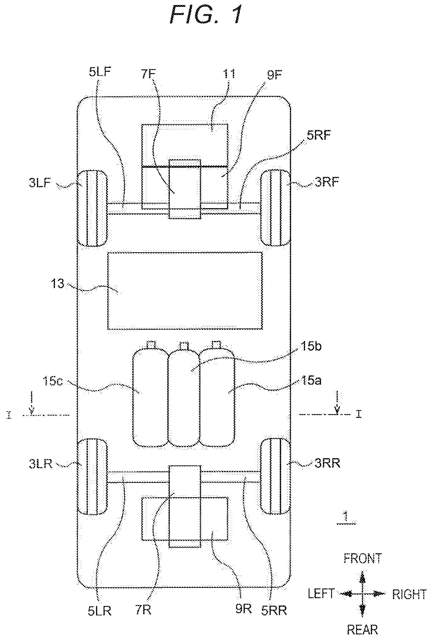
is a schematic view illustrating a layout of fuel tanks in a fuel cell vehicle according to an embodiment of the disclosure.
is a schematic view of a I-I cross section in , as viewed from the arrow direction.
is a lower side view of a support structure of the fuel tanks.
is a schematic view of a II-II cross section in , as viewed from the arrow direction.
is a diagram illustrating a structural example of a first fixing part of a first support mechanism.
is a diagram illustrating a structural example of second fixing parts of the first support mechanisms.
is a diagram illustrating a structural example of fixing parts of a second support mechanism.
is a diagram illustrating movements of the fuel tanks at the time of a side collision of the vehicle.
DETAILED DESCRIPTION
At the time of a side collision of the vehicle, a plurality of fuel tanks that are longitudinally arranged may interfere with each other to be damaged, resulting in fuel leakage. In another case, at the time of a side collision of the vehicle, even when fuel tanks move upward, it is necessary to protect occupants in the vehicle cabin.
It is desirable to provide a fuel cell vehicle that is able to reduce damage to a plurality of longitudinally arranged fuel tanks and to protect occupants in a vehicle cabin, at the time of a side collision of the vehicle.
Hereinafter, an embodiment of the disclosure will be described in detail with reference to the accompanying drawings. In the specification and the drawings, elements having substantially the same functional configuration are designated by the same reference numerals, and a duplicate description thereof will be omitted.
1. Layout of Fuel Tanks
First, a layout of fuel tanks in a fuel cell vehicle according to an embodiment of the disclosure will be described.
are schematic views illustrating a simplified layout of elements of a fuel cell vehicle (hereinafter, simply referred to as “vehicle”) 1 according to this embodiment. is a schematic plane view of the vehicle 1 as viewed from above. is a diagram schematically illustrating a I-I cross section in as viewed from the arrow direction.
The fuel cell vehicle 1 includes a fuel cell 11 , a front wheel drive motor 9 F, a rear wheel drive motor 9 R, a front wheel power transmission 7 F, a rear wheel power transmission 7 R, a secondary battery 13 , a first fuel tank 15 a , a second fuel tank 15 b , and a third fuel tank 15 c.
The fuel cell 11 and the front wheel drive motor 9 F are mounted at a front part of the vehicle 1 . The driving force that is output from the front wheel drive motor 9 F is transmitted to an axle 5 LF of a left front wheel 3 LF and to an axle 5 RF of a right front wheel 3 RF via the front wheel power transmission 7 F. The front wheel power transmission 7 F is composed of, for example, a differential gear and a clutch.
The rear wheel drive motor 9 R is mounted at a rear part of the vehicle 1 . The driving force that is output from the rear wheel drive motor 9 R is transmitted to an axle 5 LR of a left rear wheel 3 LR and to an axle 5 RR of a right rear wheel 3 RR via the rear wheel power transmission 7 R. As in the case of the front wheel power transmission 7 F, the rear wheel power transmission 7 R is composed of, for example, a differential gear and a clutch.
The vehicle 1 is mounted with an inverter and a motor control device that are not illustrated. The motor control device controls the inverter to power the front wheel drive motor 9 F and the rear wheel drive motor 9 R with charged power of the secondary battery 13 and generated power of the fuel cell 11 . The motor control device also controls the inverter to regeneratively drive the front wheel drive motor 9 F and the rear wheel drive motor 9 R so as to charge the secondary battery 13 with the regeneratively generated power.
The fuel cell 11 generates electric power through electrochemical reactions between air (oxygen) and hydrogen gas that is filled in the first fuel tank 15 a , the second fuel tank 15 b , and the third fuel tank 15 c . The generated power of the fuel cell 11 is supplied to the front wheel drive motor 9 F and the rear wheel drive motor 9 R and is charged in the secondary battery 13 . The fuel cell 11 is driven under control of a fuel cell control device, which is not illustrated.
The vehicle 1 according to this embodiment includes three fuel tanks of the first fuel tank 15 a , the second fuel tank 15 b , and the third fuel tank 15 c (hereinafter, equally called “fuel tanks 15 ” in the case of not distinguishing therebetween). Each of the fuel tanks 15 is longitudinally arranged so as to have the longitudinal directions along the vehicle longitudinal direction. The first fuel tank 15 a , the second fuel tank 15 b , and the third fuel tank 15 c are respectively provided with on-off valves 16 a to 16 c (hereinafter, equally called as “on-off valves 16 ” in the case of not distinguishing therebetween) at one ends in the longitudinal direction. The on-off valves 16 a to 16 c are positioned on a front side of the vehicle body. In the state in which the fuel tanks 15 are longitudinally arranged, the on-off valves 16 are spaced away from a side surface of the vehicle body compared with a case of transversely arranging the fuel tanks. This reduces the possibility of leakage of hydrogen gas due to damage to the on-off valves 16 at the time of a side collision of the vehicle 1 , whereby safety is improved.
The first fuel tank 15 a , the second fuel tank 15 b , and the third fuel tank 15 c are arranged in this order from right to left of the vehicle body. The second fuel tank 15 b at the middle of the three fuel tanks 15 is disposed adjacent to the first fuel tank 15 a or the third fuel tank 15 c . An axial center C 2 of the second fuel tank 15 b is positioned higher than an axial center C 1 of the first fuel tank 15 a and an axial center C 3 of the third fuel tank 15 c . The second fuel tank 15 b is partially disposed in an upper recess 23 that is provided in a floor bottom surface 21 of the vehicle body (refer to ). This enables efficiently using the space for disposing the fuel tanks 15 . The upper recess 23 may use, for example, a tunnel part in which a propeller shaft for transmitting a driving force from the front wheel side to the rear wheel side or from the rear wheel side to the front wheel side is disposed, of a related-art vehicle that is mounted with a drive source, such as an engine or a drive motor, at either one of a front part and a rear part.
The fuel cell vehicle 1 according to this embodiment, which includes the front wheel drive motor 9 F and the rear wheel drive motor 9 R at the front part and the rear part, respectively, is difficult to obtain the space for disposing the fuel tanks 15 at the front part and the rear part of the vehicle 1 . For this reason, the three fuel tanks 15 are disposed under a rear seat 25 in the vehicle cabin, between the front wheels 3 LF and 3 RF and the rear wheels 3 LR and 3 RR. The fuel tanks 15 , which are longitudinally arranged, have the on-off valves 16 that are spaced away from the side surface of the vehicle body. Thus, the fuel tanks 15 can be disposed close to the side surface of the vehicle body. This structure enables increasing the load amount of hydrogen gas, resulting in extension of the cruising range of the fuel cell vehicle 1 .
2. Support Structure of Fuel Tanks
Next, a support structure of the fuel tanks 15 of the fuel cell vehicle 1 according to this embodiment will be described.
to 6 are drawings for illustrating a support structure of the fuel tanks 15 . is a lower side view of the floor bottom surface 21 of the vehicle body. is a schematic view of a II-II cross section in , as viewed from the arrow direction. is a diagram illustrating a first fixing part 30 aa of a first support mechanism 30 a . is a diagram illustrating second fixing parts 30 ab and 30 cb of the first support mechanisms 30 a and 30 c . is a diagram illustrating a fixing part of a second support mechanism 40 a . Note that the up-down direction, the front-rear direction, and the right-left direction are illustrated in each drawing, and the illustrated front-rear direction or right-left direction is reversed in some drawings.
The first fuel tank 15 a that is positioned on a right outer side in the vehicle width direction among the three fuel tanks 15 is supported by the first support mechanisms 30 a and 30 b . The first support mechanisms 30 a and 30 b support the first fuel tank 15 a while allowing the first fuel tank 15 a to move downward of the second fuel tank 15 b , when a collision load acts from a right outside in the vehicle width direction. The third fuel tank 15 c that is positioned on a left outer side in the vehicle width direction among the three fuel tanks 15 is supported by the first support mechanisms 30 c and 30 d . The first support mechanisms 30 c and 30 d support the third fuel tank 15 c while allowing the third fuel tank 15 c to move downward of the second fuel tank 15 b , when a collision load acts from a left outside in the vehicle width direction.
The first support mechanisms 30 a and 30 b support the first fuel tank 15 a at two positions on a front side and a rear side in the longitudinal direction of the first fuel tank 15 a , respectively. The two first support mechanisms 30 a and 30 b for supporting the first fuel tank 15 a have the same structure. The first support mechanisms 30 c and 30 d support the third fuel tank 15 c at two positions on a front side and a rear side in the longitudinal direction of the third fuel tank 15 c , respectively. The first support mechanisms 30 c and 30 d for supporting the third fuel tank 15 c have the same structure as the first support mechanisms 30 a and 30 b for supporting the first fuel tank 15 a , except that right and left are reversed. The following describes the first support mechanism 30 a as an example.
The first support mechanism 30 a supports, the first fuel tank 15 a in the state of being fixed to the vehicle body at the first fixing part 30 aa on the outer side in the vehicle width direction and at the second fixing part 30 ab on the center side in the vehicle width direction. The first support mechanism 30 a includes a first support member 33 a for supporting the first fuel tank 15 a and first fixing members 31 a and 35 a that fix the first support member 33 a to the vehicle body. The first support member 33 a includes a lower bracket 33 aa and an upper bracket 33 ab that hold the first fuel tank 15 a therebetween from upper and lower sides.
The lower bracket 33 aa and the upper bracket 33 ab have strengths lower than the strength of the fuel tanks 15 and are made of, for example, belt-shaped resin molded components. The middle in the longitudinal direction of the lower bracket 33 aa is formed into a shape along the contour of a lower side of the first fuel tank 15 a and supports the first fuel tank 15 a from the lower side. The middle in the longitudinal direction of the upper bracket 33 ab is formed into a shape along the contour of an upper side of the first fuel tank 15 a and supports the upper side of the first fuel tank 15 a.
Both side parts of the lower bracket 33 aa are fixed to the vehicle body in conjunction with both side parts of the upper bracket 33 ab by the first fixing members 31 a and 35 a , respectively. In one example, the side parts on the outer side in the vehicle width direction of the lower bracket 33 aa and the upper bracket 33 ab are fixed to a side frame 25 a of the vehicle body by the first fixing member 31 a at the first fixing part 30 aa . The side parts at the middle in the vehicle width direction of the lower bracket 33 aa and the upper bracket 33 ab are fixed to a tank support frame 27 by the first fixing member 35 a at the second fixing part 30 ab . The tank support frame 27 is provided on a floor of the vehicle body.
Each of the both side parts of the lower bracket 33 aa and corresponding each of the both side parts of the upper bracket 33 ab may be mutually joined. Each of the both side parts of the lower bracket 33 aa and corresponding each of the both side parts of the upper bracket 33 ab , which are mutually joined, reliably support the first fuel tank 15 a . In this case, each of the both side parts of the lower bracket 33 aa and corresponding each of the both side parts of the upper bracket 33 ab may be joined by adhesive or welding, or may be bound by a binding band or the like.
is a lower side view of the first fixing part 30 aa . The lower bracket 33 aa and the upper bracket 33 ab have long holes 32 aa at ends on the outer side in the vehicle width direction. The long holes 32 aa have a longitudinal direction along the vehicle width direction. The long holes 32 aa penetrate through the lower bracket 33 aa and the upper bracket 33 ab . The first fixing member 31 a is, for example, a bolt, a screw, or a rivet, and passes through the long holes 32 aa to be fixed to the side frame 25 a . The first fixing member 31 a is positioned on the center side in the vehicle width direction in the long hole 32 aa . Thus, upon being strongly pulled toward the center side in the vehicle width direction, the lower bracket 33 aa and the upper bracket 33 ab move toward the center side in the vehicle width direction along the long holes 32 aa.
In order to allow the lower bracket 33 aa and the upper bracket 33 ab to move toward the center side in the vehicle width direction, at least parts of the long holes 32 aa exist on the outer side in the vehicle width direction than the first fixing member 31 a . The first fixing member 31 a may not be disposed on the center side in the vehicle width direction in the long holes 32 aa.
The lower bracket 33 aa and the upper bracket 33 ab have long holes 32 ab at ends on the center side in the vehicle width direction. The long holes 32 ab have a longitudinal direction along the vehicle width direction. The long holes 32 ab penetrate through the lower bracket 33 aa and the upper bracket 33 ab . As in the case of the first fixing member 31 a , the first fixing member 35 a passes through the long holes 32 ab to be fixed to the tank support frame 27 . The first fixing member 35 a is positioned on the center side in the vehicle width direction in the long holes 32 ab . Thus, upon being strongly pulled toward the center side in the vehicle width direction, the lower bracket 33 aa and the upper bracket 33 ab move toward the center side in the vehicle width direction along the long holes 32 ab.
is an upper side view of the second fixing part 30 ab . Note that illustrates a second fixing part 30 cb of the first support mechanism 30 c for supporting the third fuel tank 15 c , in addition to the second fixing part 30 ab of the first support mechanism 30 a for supporting the first fuel tank 15 a.
The lower bracket 33 aa and the upper bracket 33 ab have long holes 32 ab at ends on the center side in the vehicle width direction. The long holes 32 ab have a longitudinal direction along the vehicle width direction. The long holes 32 ab penetrate through the lower bracket 33 aa and the upper bracket 33 ab . As in the case of the first fixing member 31 a , the first fixing member 35 a passes through the long holes 32 ab to be fixed to the tank support frame 27 . The first fixing member 35 a is positioned on the center side in the vehicle width direction in the long holes 32 ab . Thus, upon being strongly pulled toward the center side in the vehicle width direction, the lower bracket 33 aa and the upper bracket 33 ab move toward the center side in the vehicle width direction along the long holes 32 ab.
Also as to the long holes 32 ab that are formed at the ends on the center side in the vehicle width direction of the lower bracket 33 aa and the upper bracket 33 ab , at least parts of the long holes 32 ab exist on the right outer side in the vehicle width direction than the first fixing member 35 a . The first fixing member 35 a may not be disposed on the center side in the vehicle width direction in the long holes 32 ab . The long holes 32 ab may have a U-shape that opens to a side opposite to the first fuel tank 15 a . However, in order to prevent the first fuel tank 15 a from falling off due to dislocation of the lower bracket 33 aa and the upper bracket 33 ab by vibrations or the like, the long holes 32 ab have a closed slit shape in some embodiments.
The first support mechanism 30 b for supporting the rear side of the first fuel tank 15 a is structured in a manner similar to the first support mechanism 30 a . In addition, the first support mechanisms 30 c and 30 d for supporting the third fuel tank 15 c , which is disposed on the left outer side in the vehicle width direction, are structured in a manner similar to the first support mechanism 30 a , except that right and left are inverted. That is, the first support mechanism 30 c for supporting the third fuel tank 15 c includes a first support member 33 c having a lower bracket 33 ca and an upper bracket 33 cb and also includes first fixing members 31 c and 35 c that fix the first support member 33 c to the vehicle body.
The first support mechanism 30 c supports the third fuel tank 15 c while allowing the third fuel tank 15 c to move downward of the second fuel tank 15 b , when a collision load acts from the left outside in the vehicle width direction. The first support mechanism 30 d for supporting the rear side of the third fuel tank 15 c is structured in a manner similar to the first support mechanism 30 c.
The second fuel tank 15 b , which is disposed in the middle of the three fuel tanks 15 , is supported by second support mechanisms 40 a and 40 b . The second support mechanisms 40 a and 40 b support the second fuel tank 15 b at two positions on a front side and a rear side in the longitudinal direction of the second fuel tank 15 b , respectively. The two second support mechanisms 40 a and 40 b for supporting the second fuel tank 15 b have the same structure. The following describes the second support mechanism 40 a as an example.
The second support mechanism 40 a includes a second support member 43 a for supporting the second fuel tank 15 b and second fixing members 41 a that fix the second support member 43 a to the vehicle body. The second support member 43 a includes a lower bracket 43 aa and an upper bracket 43 ab that hold the second fuel tank 15 b therebetween from upper and lower sides.
The lower bracket 43 aa and the upper bracket 43 ab have strengths lower than the strength of the fuel tanks 15 and are made of, for example, belt-shaped resin molded components. The middle in the longitudinal direction of the lower bracket 43 aa is formed into a shape along the contour of a lower side of the second fuel tank 15 b and supports the second fuel tank 15 b from the lower side. The middle in the longitudinal direction of the upper bracket 43 ab is formed into a shape along the contour of an upper side of the second fuel tank 15 b and supports the upper side of the second fuel tank 15 b.
Both side parts of the lower bracket 43 aa are fixed to the floor bottom surface 21 of the vehicle body in conjunction with both side parts of the upper bracket 43 ab by the second fixing members 41 aa and 41 ab , respectively. The both side parts of the lower bracket 43 aa and the upper bracket 43 ab are fixed to both sides of the upper recess 23 , which is provided in the floor bottom surface 21 . Also as to the second support member 43 a , each of the both side parts of the lower bracket 43 aa and corresponding each of the both side parts of the upper bracket 43 ab may be mutually joined.
is a lower side view of the fixing parts at the both side parts of the second support member 43 a . In , the middle of the second support member 43 a for supporting the second fuel tank 15 b is omitted. The second support member 43 a has long holes 42 aa and 42 ab at ends of the both side parts. The long holes 42 aa and 42 ab have a longitudinal direction along the vehicle width direction. The long holes 42 aa and 42 ab penetrate through the lower bracket 43 aa and the upper bracket 43 ab.
As in the case of the first fixing member 31 a , the second fixing members 41 a are, for example, bolts, screws, or rivets and respectively pass through the long holes 42 aa and 42 ab to be fixed to the floor bottom surface 21 . The second fixing members 41 a are positioned on the center side in the vehicle width direction in the long holes 42 aa and 42 ab , respectively. Thus, upon being strongly pulled toward the center side in the vehicle width direction, the lower bracket 43 aa and the upper bracket 43 ab move toward the center side in the vehicle width direction along the long holes 42 aa and 42 ab.
Also, the long holes 42 aa and 42 ab may have a U-shape that opens to the outer side in the vehicle width direction. However, in order to prevent them from coming off from the second fixing members 41 a , they are closed slit-shaped long holes 42 aa and 42 ab in some embodiments.
In the support structure of the fuel tanks 15 thus constructed, the second fuel tank 15 b , which is positioned in the middle of the three fuel tanks 15 , and the first fuel tank 15 a and the third fuel tank 15 c , partially overlap with one another in the up-down direction (refer to ). The axial center C 2 of the second fuel tank 15 b is positioned higher than the axial center C 1 of the first fuel tank 15 a and the axial center C 3 of the third fuel tank 15 c on the outer sides in the vehicle width direction. The second fuel tank 15 b is partially positioned in the upper recess 23 in the floor bottom surface 21 (refer to ).
A restricting member 29 is provided on an inner surface of the upper recess 23 . The restricting member 29 is disposed above the second fuel tank 15 b and restricts the upward movement range of the second fuel tank 15 b . The restricting member 29 has strength higher than the strengths of at least the floor bottom surface 21 and the fuel tanks 15 and prevents the floor bottom surface 21 from deforming when the second fuel tank 15 b is pushed from the lower side.
The form of the restricting member 29 is not specially limited, but, for example, the restricting member 29 may have a predetermined high strength as a material characteristic or may have a predetermined high strength in terms of structure, such as shape. In one example, the restricting member 29 may be a member obtained by bending one- or multi-layered steel sheet that has a high tensile strength and a predetermined thickness, or the like, or may be a structural member having a reinforcing structure, such as a rib. In some embodiments, the surface of the restricting member 29 onto which the second fuel tank 15 b is to be pressed is made flat so as to not damage the second fuel tank 15 b that is pressed thereonto.
3. Actions
The above describes the fuel cell vehicle 1 and the support structure of the fuel tanks 15 according to this embodiment. Next, actions of the fuel cell vehicle 1 and the support structure of the fuel tanks 15 according to this embodiment will be described.
is a diagram illustrating movements of the fuel tanks 15 in the support structure in , in which the movements of the fuel tanks 15 occur when a collision load acts on the first fuel tank 15 a due to a side collision from a right side of the vehicle body where the first fuel tank 15 a is positioned. illustrates the first fixing part 30 aa and the second fixing part 30 ab of the first support mechanism 30 a as viewed from a lower side and an upper side, respectively.
At the time of a side collision from the right side of the vehicle body, upon receiving a collision load from the right side in , the first fuel tank 15 a is pushed toward the center side in the vehicle width direction. At that time, the first fuel tank 15 a moves left while being guided by the long holes 32 aa and 32 ab , which are provided in the first support member 33 a (lower bracket 33 aa and upper bracket 33 ab ), and by the first fixing members 31 a and 35 a , which pass through the long holes 32 aa and 32 ab to be fixed to the side frame 25 a and the tank support frame 27 , respectively.
The first fuel tank 15 a comes into contact with the second fuel tank 15 b during the movement toward the center side in the vehicle width direction. At that time, the axial center C 2 of the second fuel tank 15 b is positioned higher than the first fuel tank 15 a , and therefore, the first fuel tank 15 a moves left downward while pushing the second fuel tank 15 b upwardly. The first support member 33 a for supporting the first fuel tank 15 a is fixed to the side frame 25 a by the first fixing member 31 a , which passes through the long hole 32 aa , and is also fixed to the tank support frame 27 by the first fixing member 35 a , which passes through the long hole 32 ab . Thus, the first fuel tank 15 a is continuously held without falling off after it moves.
The second fuel tank 15 b , which is pushed upward by the first fuel tank 15 a , moves while being guided by the long holes 42 aa and 42 ab , which are provided in the second support member 43 a (lower bracket 43 aa and upper bracket 43 ab ) for supporting the second fuel tank 15 b , and by the second fixing members 41 aa and 41 ab , which pass through the long holes 42 aa and 42 ab to be fixed to the floor bottom surface 21 . Thus, the second fuel tank 15 b is continuously held without coming off from the second support member 43 a after being pushed.
In this situation, since the second fuel tank 15 b is disposed under the vehicle cabin, it is to be prevented that the second fuel tank 15 b is pushed upward to invade the vehicle cabin that houses an occupant. For this reason, the restricting member 29 that has a predetermined strength is provided above the second fuel tank 15 b , whereby the possibility that the second fuel tank 15 b invades the vehicle cabin is reduced.
In this manner, at the time of a side collision from the right side of the vehicle body, the first fuel tank 15 a is restricted in the movement direction by the first support members 33 a and 33 b and the second fuel tank 15 b and thus moves toward a lower center side in the vehicle width direction. The first support members 33 a and 33 b are movable toward the center side in the vehicle width direction by predetermined amounts and are configured to not come off from the first fixing members 31 a , 31 b , 35 a , and 35 b , whereby they are supported so as to not fall off from the vehicle body. The second fuel tank 15 b , which is pushed upward by the first fuel tank 15 a , is restricted in movement by the restricting member 29 provided in the upper recess 23 , whereby the second fuel tank 15 b is prevented from invading the vehicle cabin.
Similarly, also in the case of a side collision from the left side of the vehicle body, the third fuel tank 15 c is restricted in the movement direction by the first support members 33 c and 33 d and the second fuel tank 15 b and thus moves toward the lower center side in the vehicle width direction. The first support members 33 c and 33 d are movable toward the center side in the vehicle width direction by predetermined amounts and are configured to not come off from the first fixing members 31 c , 31 d , 35 c , and 35 d , whereby they are supported so as to not fall off from the vehicle body. The second fuel tank 15 b , which is pushed upward by the third fuel tank 15 c , is restricted in movement by the restricting member 29 provided in the upper recess 23 , whereby the second fuel tank 15 b is prevented from invading the vehicle cabin.
4. Advantages of Embodiments
As described above, in the fuel cell vehicle 1 according to this embodiment, the axial center C 2 of the second fuel tank 15 b on the center side in the vehicle width direction is positioned higher than the axial centers C 1 and C 3 of the first fuel tanks 15 ( 15 a and 15 c ) on the outer sides in the vehicle width direction. In addition, the fuel tanks 15 ( 15 a and 15 c ) on the outer sides in the vehicle width direction are supported while being allowed to move toward the lower side of the second fuel tank 15 b , by the first support mechanisms 30 a to 30 d . Thus, at the time of a side collision, the fuel tanks 15 ( 15 a and 15 c ), which are disposed on the outer sides in the vehicle width direction, move toward the lower side of the second fuel tank 15 b at the middle in the vehicle width direction without falling off. This reduces the possibility of damage to the fuel tanks 15 due to mutual interference of the fuel tanks 15 . Moreover, the restricting member 29 restricts the movement to the vehicle cabin of the second fuel tank 15 b , which is configured to move the fuel tanks 15 ( 15 a and 15 c ) that are disposed on the outer sides in the vehicle width direction, toward the lower center side in the vehicle width direction. This enables protecting occupants in the vehicle cabin.
The fuel cell vehicle 1 according to this embodiment includes the front wheel drive motor 9 F and so on at the front part of the vehicle 1 and includes the rear wheel drive motor 9 R and so on at the rear part of the vehicle 1 . The plural fuel tanks 15 are longitudinally arranged under the rear seat 35 of the vehicle cabin between the front wheels 3 LF and 3 RF and the rear wheels 3 LR and 3 RR. Thus, an impact of a collision from the front side of the vehicle 1 is hardly transmitted to the fuel tanks 15 . In addition, the rear wheel drive motor 9 R and a rigid body for supporting thereof protect the fuel tanks 15 from a collision from the rear side of the vehicle 1 . This reduces the possibility of damage to the fuel tanks 15 in case of occurrence of a collision from the front side or the rear side, as well as occurrence of a side collision from the right side or the left side.
In the fuel cell vehicle 1 according to this embodiment, the second fuel tank 15 b at the middle in the vehicle width direction is partially disposed in the upper recess 23 , which is provided in the floor bottom surface 21 of the vehicle body. In one example, the second fuel tank 15 b is partially disposed in a space of a tunnel section in which a propeller shaft is disposed, in a conventional all-wheel-drive vehicle. Thus, the space for disposing the fuel tanks 15 is widely obtained, which makes it possible to increase the load amount of hydrogen gas.
In the fuel cell vehicle 1 according to this embodiment, the second fuel tank 15 b at the middle in the vehicle width direction has a diameter that is smaller than the diameters of the fuel tanks 15 ( 15 a and 15 c ) on the outer sides in the vehicle width direction. With this structure, the second fuel tank 15 b is easy to partially dispose in the upper recess 23 , whereby the fuel tanks 15 can be mounted away from a road surface.
The embodiment of the disclosure has been described in detail above with reference to the accompanying drawings. The disclosure is not limited to such an embodiment. It is apparent that those who have ordinary knowledge in the technical field to which the disclosure pertains would conceive various changes and modifications within the scope of the appended claims, and it is to be understood that such changes and modifications also fall within the technical scope of the disclosure.
For example, the structure of the support mechanism, which supports the fuel tanks 15 ( 15 a and 15 c ) on the outer sides in the vehicle width direction while allowing them to move toward the lower side of the second fuel tank 15 b , is not limited to the example described above. The first support member may not be a bracket and may employ another appropriate member. In one example, guide grooves or guide holes for restricting the movement directions of the fuel tanks 15 may be provided in the vehicle body, and fixing members may be fixed to such guide grooves to support each of the fuel tanks 15 . The structure of the support mechanism can be variously modified.
As described above, the disclosure enables reducing damage to the plurality of longitudinally arranged fuel tanks and protecting occupants in the vehicle cabin, at the time of a side collision of the vehicle.
Figures (5)
Citations
This patent cites (54)
- US4457525
- US5658013
- US6227230
- US11008041
- US20020121772
- US20030189334
- US20040101745
- US20060027406
- US20060033322
- US20070119646
- US20080023957
- US20080111048
- US20080283316
- US20090309349
- US20100051625
- US20100252353
- US20110174856
- US20110259933
- US20120080250
- US20150329242
- US20150367726
- US20160039282
- US20160096495
- US20160097487
- US20170082240
- US20170240039
- US20170240045
- US20170282709
- US20180272863
- US20180326842
- US20190160941
- US20190263450
- US20210245811
- US20210260994
- US20220009347
- US20220041053
- US20220097516
- US20220105799
- US20220144078
- US20220219528
- US20220402355
- US20230016788
- US20230173914
- US110356222
- US102017004902
- USS57-199175
- US2008-143464
- US2010-111282
- US2010-247606
- US2011-042208
- US2017-100515
- US2017-144746
- US2019-098802
- US2019-147500