Abstract
A transfer robot includes one arm, another arm, a motor, and a brake. The another arm is connected to the one arm via a shaft such that the another arm is rotatable relatively with respect to the one arm around a shaft axis of the shaft. The motor includes a rotor rotatable around the shaft axis to rotate the another arm around the shaft axis, and a stator connected to the one arm. The brake is provided at the another arm to apply a force to the stator so as to suppress relative rotation between the stator and the rotor when electric power is not supplied to the motor.
Claims (29)
1. A transfer robot comprising: a main body; one arm connected to the main body rotatably around a first axis; another arm connected to the one arm via a shaft such that the another arm is rotatable relatively with respect to the one arm around a shaft axis of the shaft; the shaft comprising: a first shaft portion fixed to the one arm and having an axis coaxial with the shaft axis; and a second shaft portion fixed to the another arm and connected to the first shaft portion via a bearing such that the second shaft portion is rotatable around the shaft axis relatively with respect to the first shaft portion; and a motor provided at the one arm or the another arm to rotate the second shaft portion relatively with respect to the first shaft portion around the shaft axis.
Show 28 dependent claims
2. The transfer robot according to claim 1 , wherein the main body is installed on a floor surface.
3. The transfer robot according to claim 1 , wherein the one arm is connected to the main body via a rotatable shaft.
4. The transfer robot according to claim 3 , wherein the rotatable shaft is movable along a rotation axis of the rotatable shaft with respect to the main body.
5. The transfer robot according to claim 1 , wherein the first axis is substantially parallel to the shaft axis.
6. The transfer robot according to claim 1 , wherein the motor is provided at the one arm and the motor comprises a rotor connected to the second shaft portion rotatably around the shaft axis; and a stator connected to the first shaft portion.
7. The transfer robot according to claim 1 , further comprising: a brake provided at the another arm to apply a force so as to suppress relative rotation between the one arm and the another arm when electric power is not supplied to the motor.
8. The transfer robot according to claim 1 , further comprising: a plurality of hands rotatably connected to the another arm via a second shaft.
9. The transfer robot according to claim 8 , wherein the another arm comprises a plurality of rotary motors and a plurality of belts therein, and wherein driving force of each of the plurality of rotary motors is transmitted to each of the plurality of hands via each of the plurality of belts.
10. The transfer robot according to claim 9 , wherein the plurality of hands includes a first hand and a second hand, wherein the plurality of rotary motors includes a first rotary motor and a second rotary motor, the first rotary motor having a first output shaft projecting in a first direction, the second rotary motor having a second output shaft projecting in a second direction opposite to the first direction, and wherein the plurality of belts includes a first belt and a second belt which are arranged such that at least a portion of the first belt and the second belt is nested when viewed along the first direction.
11. The transfer robot according to claim 1 , wherein the one arm has a first connection portion, the another arm has a second connection portion that is connected to the first connection portion of the one arm via the shaft, the motor is provided at the first connection portion of the one arm and comprises a rotor rotatable around the shaft axis to rotate the another arm around the shaft axis, and a stator connected to the first connection portion of the one arm, the first connection portion of the one arm projects toward the another arm and has a thickness larger than a thickness of a portion other than the first connection portion of the one arm, and the another arm has another portion which projects toward the one arm and which has a thickness larger than a thickness of the second connection portion of the another arm.
12. The transfer robot according to claim 11 , further comprising: a plurality of hands rotatably connected to the another arm via a second shaft, wherein the another arm comprises a plurality of rotary motors and a plurality of belts therein, and driving force of each of the plurality of rotary motors is transmitted to each of the plurality of hands via each of the plurality of belts, and wherein the plurality of rotary motors and the plurality of belts are arranged in the another portion of the another arm.
13. The transfer robot according to claim 9 , wherein the motor comprises a rotor connected to the second shaft portion rotatably around the shaft axis, and a stator connected to the first shaft portion and having a through hole extending along the shaft axis, and a cable for each of the plurality of rotary motors is provided inside the one arm and inside the another arm via the through hole and an opening provided on a lower surface side of the one arm.
14. The transfer robot according to claim 13 , further comprising: a removable cover closing the through hole and the opening.
15. The transfer robot according to claim 4 , wherein the rotatable shaft comprises a built-in motor therein to rotate the one arm.
16. The transfer robot according to claim 6 , wherein the stator has a cylindrical shape, the rotor faces an inner peripheral side of the stator, and the motor further comprises a base that supports the rotor.
17. The transfer robot according to claim 16 , wherein the base comprises the bearing that rotatably supports the rotor.
18. The transfer robot according to claim 17 , wherein the bearing is disposed in a hollow region of the stator.
19. A robot system comprising: the transfer robot according to claim 1 ; and control circuitry configured to control the transfer robot.
20. The transfer robot according to claim 1 , wherein an entirety of the motor is provided inside the one arm.
21. The transfer robot according to claim 1 , further comprising: a hand connected to the another arm.
22. The transfer robot according to claim 1 , wherein the one arm has an upper surface and the another arm has a lower surface, the upper surface being opposite to the lower surface when the one arm and the another arm overlap, and wherein the shaft axis is substantially perpendicular to the upper surface and the lower surface.
23. The transfer robot according to claim 7 , wherein the brake is configured not to suppress the relative rotation when electric power is supplied to the motor.
24. The transfer robot according to claim 7 , wherein the brake is provided inside the another arm.
25. The transfer robot according to claim 7 , wherein the motor comprises a rotor connected to the second shaft portion rotatably around the shaft axis, a stator connected to the first shaft portion, and the brake comprises a friction band wound around an outer periphery of a shaft portion which has an axis coaxial with the shaft axis and which is connected to the stator.
26. The transfer robot according to claim 7 , wherein the motor comprises a rotor connected to the second shaft portion rotatably around the shaft axis, a stator connected to the first shaft portion, and the brake is configured to apply a frictional force to the stator.
27. The transfer robot according to claim 6 , wherein the stator is provided to surround the rotor.
28. The transfer robot according to claim 1 , wherein the motor is provided at the another arm and the motor comprises a rotor connected to the first shaft portion rotatably around the shaft axis; and a stator connected to the second shaft portion.
29. The transfer robot according to claim 1 , wherein an entirety of the motor is provided inside the another arm.
Full Description
Show full text →
CROSS-REFERENCE TO RELATED APPLICATIONS
The present application is a continuation application of the U.S. patent application Ser. No. 16/435,565, filed Jun. 10, 2019, which claims priority under 35 U. S. C. § 119 to Japanese Patent Application No. 2018-133294, filed Jul. 13, 2018. The contents of these applications are incorporated herein by reference in their entirety.
BACKGROUND
Technical Field
An embodiment disclosed herein relate to a transfer robot and a robot system.
Related Art
Conventionally, a transfer robot such as a horizontal articulated robot that transfers an object to be transferred is known. Further, Japanese Patent Application Laid-Open No. 2005-039047 describes a substrate transfer robot that transfers a substrate as an object to be transferred and incorporates a motor of a finished product in an arm.
SUMMARY
According to one aspect of the present invention, a transfer robot includes one arm, another arm, a motor, and a brake. The another arm is connected to the one arm via a shaft such that the another arm is rotatable relatively with respect to the one arm around a shaft axis of the shaft. The motor includes a rotor rotatable around the shaft axis to rotate the another arm around the shaft axis, and a stator connected to the one arm. The brake is provided at the another arm to apply a force to the stator so as to suppress relative rotation between the stator and the rotor when electric power is not supplied to the motor.
According to another aspect of the present invention, a transfer robot includes one arm having a first connection portion, another arm, and a motor. The another arm has a second connection portion that is connected to the first connection portion of the one arm via a shaft such that the another arm is rotatable relatively with respect to the one arm around a shaft axis of the shaft. The motor is provided at the first connection portion of the one arm. The motor includes a rotor rotatable around the shaft axis to rotate the another arm around the shaft axis, and a stator connected to the first connection portion of the one arm. The first connection portion of the one arm projects toward the another arm and has a thickness larger than a thickness of a portion other than the first connection portion of the one arm. The another arm has another portion which projects toward the one arm and which has a thickness larger than a thickness of the second connection portion of the another arm.
According to further aspect of the present invention, a transfer robot includes one arm, another arm, a motor, and a lift portion. The another arm is connected to the one arm via a shaft such that the another arm is rotatable relatively with respect to the one arm around a shaft axis of the shaft. The motor includes a rotor rotatable around the shaft axis to rotate the another arm around the shaft axis, and a stator connected to the one arm. The lift portion is configured to raise and lower the one arm and the another arm and includes a built-in motor integrated with the lift portion. The built-in motor is configured to rotate the one arm.
According to the other aspect of the present invention, a transfer robot includes one arm, another arm, and a motor. The another arm is connected to the one arm via a shaft such that the another arm is rotatable relatively with respect to the one arm around a shaft axis of the shaft. The motor is provided at the one arm and includes a rotor rotatable around the shaft axis to rotate the another arm around the shaft axis. The shaft includes a first shaft portion and a second shaft portion. The first shaft portion is fixed to the one arm and has an axis coaxial with the shaft axis. The second shaft portion is fixed to the another arm and is connected to the first shaft portion via a bearing such that the second shaft portion is rotatable around the shaft axis relatively with respect to the first shaft portion.
BRIEF DESCRIPTION OF DRAWINGS
A more complete appreciation of the invention and many of the attendant advantages thereof will be readily obtained as the same becomes better understood by reference to the following detailed description when considered in connection with the accompanying drawings.
is a schematic view showing an outline of a transfer robot.
is a cross-sectional view of a built-in motor.
is a perspective view of the transfer robot.
is a side view of a first arm, a second arm, and a hand.
is a perspective view of the hand.
A is a first perspective view of the first arm.
B is a second perspective view of the first arm.
A is a first schematic view of the second arm.
B is a second schematic view of the second arm.
A is a perspective view of a lift portion.
B is a schematic view of a lift portion.
is a perspective view showing a second arm according to a modification.
is a block diagram of a robot system.
DETAILED DESCRIPTION
The embodiments will now be described with reference to the accompanying drawings, wherein like reference numerals designate corresponding or identical elements throughout the various drawings.
A transfer robot and a robot system disclosed in the present application will be described in detail below, with reference to the accompanying drawings. Herein, this invention is not limited to the embodiment described below.
In the embodiment described below, although expressions such as “parallel”, “center”, “symmetry”, “reverse direction”, and “cylinder” may be used, it is not necessary to strictly meet these states. That is, each expression mentioned above shall accept deviations, such as manufacture accuracy, installation accuracy, processing accuracy, and detection accuracy.
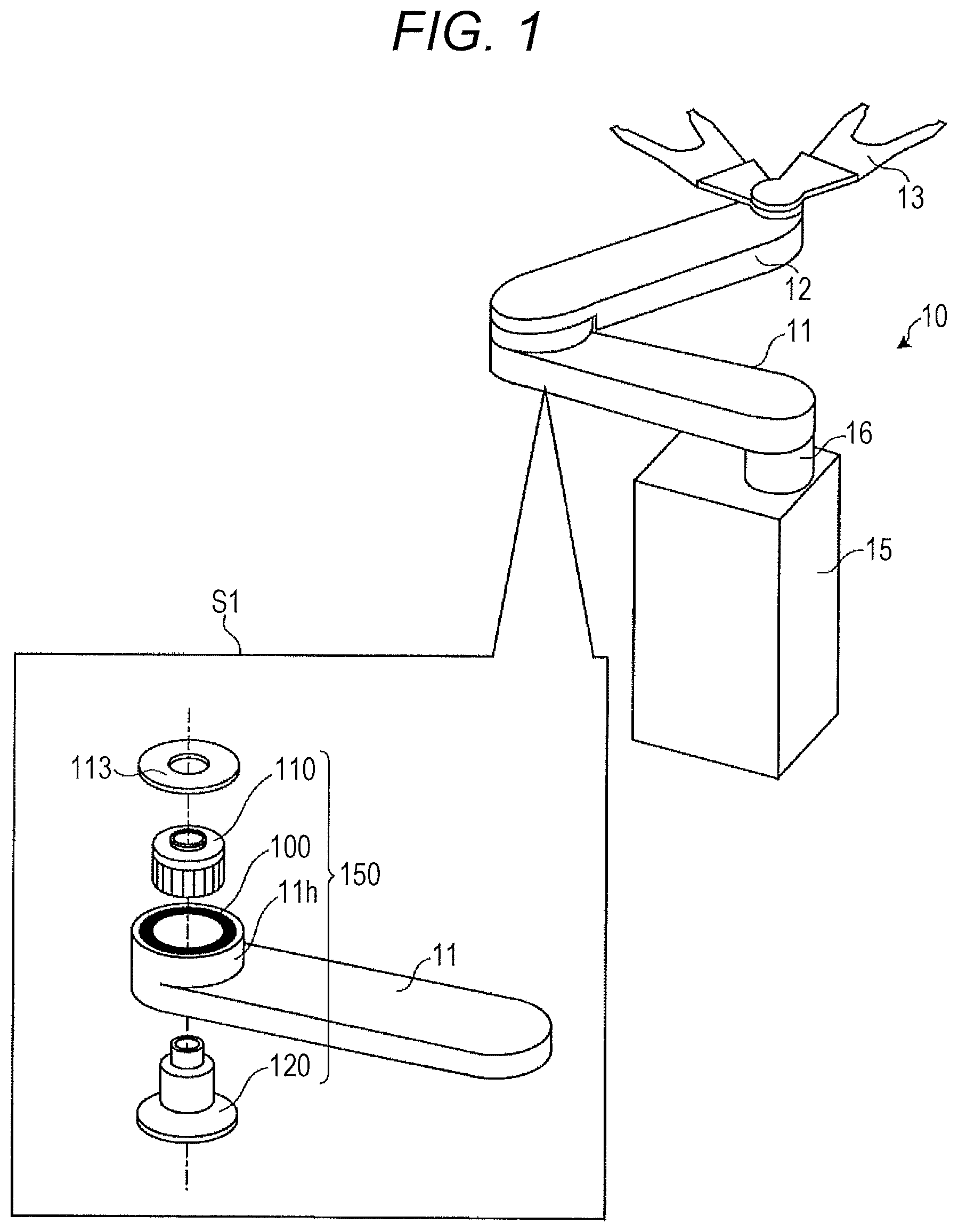
First, an outline of a transfer robot 10 according to the embodiment will be described with reference to . is a schematic view showing the outline of the transfer robot 10 . is a perspective view of the transfer robot 10 viewed obliquely from above and an exploded perspective view of a first arm 11 (see S 1 of ).
As shown in , the transfer robot 10 includes a main body 15 installed on a floor surface and the like and a lift portion 16 rising and lowering with respect to the main body 15 . The lift portion 16 raises and lowers the first arm 11 and a second arm 12 which are horizontal link arms. A hand 13 is provided on the tip end side of the second arm 12 . The hand 13 can hold an object to be transferred such as a substrate for semiconductor.
Although two hands 13 are shown in , one or three or more hands 13 may be provided. Although the two arms (the first arm 11 and the second arm 12 ) are shown as horizontal link arms in , three or more horizontal link arms may be provided.
Here, the transfer robot 10 includes an arm-integrated built-in motor 150 as shown in S 1 of . exemplifies a case where the first arm 11 includes the built-in motor 150 which causes the second arm 12 to pivot.
Specifically, the built-in motor 150 includes a stator holding portion 11 h formed in the arm and a stator portion (a stator) 100 held by the stator holding portion 11 h . The built-in motor 150 further includes a base 120 and a rotor portion (a rotor) 110 supported by the base 120 and rotated relative to the base 120 .
Here, the stator portion 100 and the base 120 , which are components that do not rotate relative to the stator holding portion 11 h , may be collectively referred to as the stator portion 100 . That is, among the components of the built-in motor 150 , the components that do not rotate relative to the stator holding portion 11 h may be collectively referred to as the “stator portion 100 ”, and the components that rotate relative to the stator holding portion 11 h may be collectively referred to as the “rotor portion 110 ”.
Thus, when the component that does not rotate is referred to as the stator portion 100 and the component that rotates is referred to as the rotor portion 110 , it can be said that the built-in motor 150 has a shape in which the rotor portion 110 is embedded in a recess between a non-rotating shaft (shaft portion 122 ) and a magnetic field generating portion (motor core 100 a and motor winding 100 b ) in the stator portion 100 . That is, the rotor portion 110 is embedded in a hollow region within the thickness of the stator portion 100 , so that the built-in motor 150 achieves a reduction in height of the motor.
An attachment portion 113 which rotates together with the rotor portion 110 serves as a lid that covers an opening on the second arm 12 side in the stator holding portion 11 h . The base 120 serves as a lid that covers an opening on the opposite side to the second arm 12 in the stator holding portion 11 h . The second arm 12 is attached to the attachment portion 113 .
As shown in S 1 of , the stator portion 100 , the rotor portion 110 , and the base 120 are accommodated in the stator holding portion 11 h . That is, the built-in motor 150 uses the stator holding portion 11 h formed in the first arm 11 instead of a case for accommodating the stator portion 100 , the rotor portion 110 and the base 120 .
As described above, since the transfer robot 10 includes the arm-integrated built-in motor 150 , the arm can be miniaturized as compared with the configuration in which a so-called finished motor having a case is used. This makes it possible to contribute to thinning of the arm and narrowing of the width of the arm.
The built-in motor 150 does not have a built-in reduction gear and an external reduction gear. Therefore, the built-in motor 150 can directly cause the arm (the second arm 12 in ) to pivot. For this reason, as compared with the configuration in which a reduction gear is used, vibration, an operation error, and a mechanical loss can be suppressed.
Hereinafter, the configuration of the built-in motor 150 will be described in more detail with reference to . is a cross-sectional view of the built-in motor 150 . shows a cross-sectional view cut along a plane including the axis of rotation of the second arm (the axis of rotation of the built-in motor 150 ) and along the extending direction of the first arm 11 .
As shown in , the stator holding portion 11 h formed at an end of the first arm 11 has a substantially cylindrical shape that protrudes to the upper surface side of the first arm, and the stator portion 100 is fitted to the inner periphery by so-called shrink fitting or the like. For example, when the stator portion 100 at normal temperature is inserted into the heated stator holding portion 11 h , the stator holding portion 11 h contracts in a cooling process to hold the stator portion 100 . The stator portion 100 may be fixed to the stator holding portion 11 h with an adhesive. Alternatively, the stator portion 100 may be fixed to the stator holding portion 11 h by inserting a pin or the like radially from the outer peripheral side of the stator holding portion 11 h toward the motor core 100 a of the stator portion 100 .
First, the stator portion 100 will be described. The stator portion 100 is integrally solidified by molding, for example, the motor core 100 a on which a silicon steel plate is stacked and the motor winding 100 b wound around teeth of the motor core 100 a with a resin or the like and is formed into a cylindrical shape. The motor winding 100 b generates a magnetic field by energization. The motor winding 100 b may be wound around a plurality of bobbins made of resin or the like, and the bobbins may be attached to the teeth. The motor core 100 a may have a coreless shape without teeth (inner core), and in the stator portion 100 , the motor winding 100 b may be molded on an inner periphery of an outer core.
The stator portion 100 has a cylindrical shape, and has the outer peripheral side in contact with the stator holding portion 11 h and the inner peripheral side facing the outer peripheral side of the rotor portion 110 at an interval. That is, in the built-in motor 150 , the stator portion 110 normally accommodated in the case is accommodated in the stator holding portion 11 h of the first arm 11 .
A winding cable 100 c for energizing the motor winding 100 b is guided to a proximal end of the first arm 11 via an internal space (an internal space below the stator holding portion 11 in ) which does not interfere with the rotor portion 110 on the inner peripheral side of the stator portion 100 . Although the winding cable 100 c is accessible from below the first arm 11 , this point will be described later with reference to .
Next, the rotor portion 110 will be described. The rotor portion 110 has a cylindrical shape and includes a cylindrical shaft portion 111 corresponding to a yoke and a magnet 112 fixed to the outer peripheral side of the shaft portion 111 with an adhesive or the like. Each of the magnets 112 has, for example, a rectangular shape in which the direction along the axis of rotation of the rotor portion 110 is longitudinal and the direction along the outer periphery is lateral, and the magnets 112 are spread across the entire outer periphery of the shaft portion 111 at predetermined intervals.
On the other hand, the inner peripheral side of the shaft portion 111 is fixed to the outer peripheral side of the rotating portion 123 in the base 120 . That is, the rotor portion 110 rotates around a rotation centerline of the rotating portion 123 . Here, the rotation centerline of the rotating portion 123 corresponds to the axis of rotation of the second arm 12 described above.
The attachment portion 113 having a through hole 113 h is fixed to an end surface of the shaft portion 111 on the second arm 12 side (upper end surface in ). Here, the attachment portion 113 is used to fix the second arm 12 . The attachment portion 113 also serves as a lid for closing an opening on the second arm 12 side in the stator holding portion 11 h.
Next, the base 120 will be described. As shown in , the base 120 fixed to a tip end portion of the first arm 11 has a shape in which a hollow cylinder stands up from a disk having a through hole in a central portion thereof. The base 120 includes an encoder portion 121 , a shaft portion 122 , and a rotating portion 123 .
The encoder portion 121 closes an opening (a lower opening in ) on the opposite side of the second arm 12 in the stator holding portion 11 h . On the upper surface side of the encoder portion 121 , a processing substrate 121 e of the encoder is provided.
On the lower surface side of the rotating portion 123 which rotates with the rotor portion 110 , a disk having a repeating pattern such as slits and irregularities is provided along the circumferential direction. On the upper surface side of the processing substrate 121 e , a light emitting portion and a light receiving portion are provided, for example. The processing substrate 121 e detects reflected light in which light emitted from the light emitting portion toward the rotating portion 123 is reflected by the above-described pattern to detect a state of rotation of the rotor portion 110 .
As shown in , an encoder cable 121 c is connected to the processing substrate 121 e , and power supply to the processing substrate 121 e and output of signals such as detection results are performed. The encoder cable 121 c is guided to the proximal end of the first arm 11 via an internal space of the stator holding portion 11 h below the rotor portion 110 . Although the encoder cable 121 c is accessible from below the first arm 11 , this point will be described later with reference to .
Here, the built-in motor 150 does not have a reduction gear and directly causes the second arm 12 to pivot. In the second arm 12 , the turning angle is limited to less than 360 degrees by a mechanical stopper or the like. Therefore, the built-in motor 150 does not make one rotation.
Generally, in a motor that makes one or more rotations, the encoder detects how many rotations the motor has made from a reference position, and stores the detection result. For this reason, the rotating portion 123 is usually provided with a disk magnetized with a mark that indicates that one rotation has made, and the processing substrate 121 e is usually provided with a circuit that detects magnetic force and a volatile memory that records the number of rotations. Then, a battery is provided which energizes the volatile memory via the encoder cable 121 c . The battery is provided, for example, on the inner side surface of the main body 15 (see ) in consideration of maintainability.
On the other hand, since the rotation of the built-in motor 150 is less than one rotation, it is not necessary to provide the above-described “magnetized disk” in the rotating portion 123 . In addition, the circuit, volatile memory, and battery described above are also unnecessary. Therefore, with the built-in motor 150 , the structure can be simplified, which can also contribute to cost reduction and miniaturization.
The shaft portion 122 has a cylindrical shape rising from the encoder portion 121 , and has an axial length which protrudes from the first arm 11 and reaches the inside of the second arm 12 . A cylindrical cable guide 12 g fixed to the second arm 12 is inserted into the inner peripheral side of the shaft portion 122 .
A cable in the second arm 12 is routed inside the first arm 11 via the cable guide 12 g . As described above, by using the cable guide 12 g , it is possible to prevent rubbing of the cable and the shaft portion 122 accompanying turning of the second arm 12 .
On the outer peripheral side of the shaft portion 122 , a first bearing b 1 , a spacer bs, and a second bearing b 2 are provided. Here, the inner peripheral sides of the first bearing b 1 and the second bearing b 2 are fixed to the shaft portion 122 . The spacer bs is used to maintain a distance between the first bearing b 1 and the second bearing b 2 at a predetermined interval.
A bearing presser 122 a is provided on the tip end side (the second bearing b 2 side) of the shaft portion 122 . Here, when assembling, the first bearing b 1 , the spacer bs, and the second bearing b 2 are inserted into the rotating portion 123 , and the rotating portion 123 into which the bearing and so on are inserted is inserted into the shaft portion 122 . Each part is assembled by attaching the bearing presser 122 a . The bearing presser 122 a and the shaft portion 122 may be collectively referred to as the shaft portion 122 .
On the other hand, the rotating portion 123 is fixed to the outer peripheral side of the first bearing b 1 and the second bearing b 2 . The rotating portion 123 has a cylindrical shape, and while the inner peripheral side is fixed to the outer peripheral sides of the first bearing b 1 and the second bearing b 2 , and the outer peripheral side is fixed to the inner peripheral side of the rotor portion 110 . Consequently, the rotor portion 110 is rotated relative to the base 120 .
Thus, the first bearing b 1 and the second bearing b 2 rotatably support the rotor portion 110 . Since the base 120 includes the bearings, the configuration of the rotor portion 110 can be simplified, and, at the same time, assemblability of the built-in motor 150 can be improved.
As shown in , the first bearing b 1 and the second bearing b 2 are accommodated in a thickness (thickness in the direction in alignment with the axis of rotation of the rotor portion 110 ) range of the cylindrical stator portion 100 . By thus arranging the bearing that allows the rotor portion 110 to rotate, it is possible to reduce the height of the built-in motor 150 .
Here, when the rotor portion 110 is assembled to the base 120 , for example, the shaft portion 111 and the rotating portion 123 are fastened with a bolt or the like. Thus, the rotor portion 110 is fixed to the rotating portion 123 . The rotor portion 110 may be fixed to the rotating portion 123 by adhesion or the like.
Thus, the stator portion 110 is fixed to the stator holding portion 11 h from above the first arm 11 , and the base 120 is fixed to the stator holding portion 11 h from below the first arm 11 . Since the rotor portion 110 is fixed to the base 120 from above the first arm 11 , the built-in motor 150 is completed.
Although shows the case where the first arm 11 includes the built-in motor 150 which causes the second arm 12 to pivot, the second arm 12 may include the built-in motor 150 which causes the second arm 12 to pivot. This point will be described later with reference to .
Although shows the case where the bearings (the first bearing b 1 and the second bearing b 2 ) are provided on the base 120 side and the rotor portion 110 rotates relative to the base 120 , the bearings may be provided on the rotor portion 110 side. In this case, the outer peripheral side of the bearing may be fixed to the inner peripheral side of the shaft portion 111 in the rotor portion 110 , and the rotor portion 110 to which the bearing is fixed may be fitted to the outer peripheral side of the shaft portion 122 in the base 120 .
Although the two bearings (the first bearing b 1 and the second bearing b 2 ) are shown in , one or three or more bearings may be provided. The spacer bs provided between the bearings may be omitted.
Although the single built-in motor 150 for arm pivoting is shown in , a plurality of the built-in motors 150 may be provided. For example, the built-in motor 150 which causes the first arm 11 to pivot and the built-in motor 150 which causes the second arm 12 to pivot may be provided at both ends of the first arm 11 . The built-in motor 150 which causes the second arm 12 to pivot may be provided at the proximal end of the second arm 12 , and the built-in motor 150 which causes the first arm 11 to pivot may be provided at the proximal end of the first arm 11 .
Next, the configuration of the transfer robot 10 will be further described with reference to . is a perspective view of the transfer robot 10 . As shown in , the transfer robot 10 includes the main body 15 , the lift portion 16 , the first arm 11 , the second arm 12 , and a plurality of the hands 13 .
Here, in order to distinguish each hand, capital alphabetic characters are appended to the end like a hand 13 A and a hand 13 B, and when not distinguishing each hand, it is described as the hand 13 . In the present embodiment, the same may be adopted for other components.
Although shows the transfer robot 10 including the two hands 13 A and 13 B, any number of the hands 13 may be provided. Further, it is preferable that a lift axis A 0 , a first axis A 1 , a second axis A 2 , and a third axis A 3 shown in be parallel to each other.
The main body 15 incorporates a mechanism for raising and lowering the lift portion 16 . The lift portion 16 rises and lowers along the lift axis A 0 shown in and supports the proximal end of the first arm 11 rotatably around the first axis A 1 . The lift portion 16 itself may be rotated about the first axis A 1 .
The first arm 11 supports, at its tip end, the proximal end of the second arm 12 rotatably around the second axis A 2 . The second arm 12 supports, at its tip end, the proximal ends of the hands 13 A and 13 B rotatably around the third axis A 3 . The hands 13 A and 13 B include a base portion 13 a and a fork portion 13 b.
Thus, the transfer robot 10 is a three-link horizontal articulated robot having the first arm 11 , the second arm 12 , and the hand 13 . As described above, since the transfer robot 10 has a lift mechanism, the transfer robot 10 can access objects to be transferred such as substrates arranged at different heights.
Next, the appearance of the first arm 11 , the second arm 12 , and the hand 13 will be described with reference to . is a side view of the first arm 11 , the second arm 12 , and the hand 13 . shows the first arm 11 , the second arm 12 , and the hand 13 in the folded posture.
In , the first axis A 1 , the second axis A 2 , and the third axis A 3 shown in are shown for reference. The “folded posture” refers to a posture in which the tip end of the second arm 12 faces the proximal end of the first arm 11 and the tip end of the hand 13 faces the proximal end of the second arm 12 .
As shown in , the bottom surface side of the first arm 11 is substantially flat. On the other hand, on the upper surface side, an upper surface of an end on the side of the second axis A 2 has a stepped shape higher than an upper surface of an end on the side of the first axis A 1 . As described above, the upper surface of the end on the second axis A 2 side protrudes toward the second arm 12 in order to dispose the built-in motor 150 shown in in the first arm 11 .
Thus, in the side view, in the first arm 11 , thickness of an end (an example of “a first connection portion”) where the built-in motor 150 is disposed is larger than thickness of other portions, and the first arm 11 has a shape protruding toward the second arm 12 .
As shown in , the upper surface side of the second arm 12 is substantially flat. On the other hand, on the bottom surface side, a lower surface of one end on the side of the second axis A 2 has a stepped shape higher than a bottom surface of the other end. The reason why the bottom surface of the end on the second axis A 2 side is thus recessed from the bottom surface of the other end is to avoid the protruding shape of the first arm 11 described above.
Thus, in the side view, in the second arm 12 , thickness on the other end side is larger than thickness on the side of the end (an example of “a second connection portion”) corresponding to the second axis A 2 , and the second arm 12 has a shape protruding toward the first arm 11 . Therefore, a volume of the thick portion can be increased, and it is easy to secure inside a space to store a mechanism for driving the hand 13 .
The hand 13 is provided on an upper surface of an end of the second arm 12 opposite to the end on the second axis A 2 side. The two hands 13 are provided in order of the hand 13 B and the hand 13 A as viewed from the second arm 12 along the third axis A 3 .
Next, the configuration of the hand 13 will be described in more detail with reference to . is a perspective view of the hand 13 . corresponds to a view of the hand 13 viewed obliquely from above.
As shown in , the hand 13 includes the base portion 13 a and the fork portion 13 b . The proximal end side of the base portion 13 a is supported by the second arm 12 (see ) so as to be rotatable about the third axis A 3 . The fork portion 13 b is provided on the tip end side of the base portion 13 a , and the tip end side of the fork portion 13 b is bifurcated.
As shown in , a friction portion 13 bb is provided on an upper surface 13 ba of the fork portion 13 b . For example, the friction portion 13 bb is an O-ring fixed so as to be partially embedded in a groove formed on the upper surface 13 ba.
As a material of the O-ring, for example, a resin such as silicon can be used. The friction portion 13 bb prevents displacement of a transferred object such as a substrate by frictional force with the transferred object. A claw projecting upward may be provided at a tip end 13 bc of the fork portion 13 b . This makes it possible to prevent falling of the object to be transferred.
Although the friction portion 13 bb is illustrated in , a holding mechanism such as an adsorption mechanism for adsorbing an object to be transferred or a gripping mechanism for gripping an object to be transferred may be used.
Next, the configuration of the first arm 11 will be described in more detail with reference to A and 6 B . A is a first perspective view of the first arm 11 , and B is a second perspective view of the first arm 11 . A corresponds to a perspective view of the first arm 11 viewed obliquely from above, and B corresponds to a perspective view of the first arm 11 viewed obliquely from below.
As shown in A , the built-in motor 150 is provided at an end on the second axis A 2 side in the first arm 11 . The stator holding portion 11 h corresponding to the case of the built-in motor 150 protrudes upward from the upper surface of the first arm 11 . The attachment portion 113 fixed to the shaft portion 111 in the rotor portion 110 (see ) rotates around the second axis A 2 . The second arm 12 is fixed to the attachment portion 113 .
The shaft portion 122 (see ) in the base 120 (see ) protrudes from the attachment portion 113 along the second axis A 2 . Since the base 120 is fixed to the first arm 11 , the shaft portion 122 does not rotate. The first axis A 1 which is a turning center of the first arm 11 is set at an end opposite to the end on the second axis A 2 side.
B shows the end on the second axis A 2 side in the first arm 11 and the second arm 12 . As shown in B , a through hole 120 h is provided in the bottom surface of the encoder portion 121 in the base 120 . The through hole 120 h communicates with an opening of the shaft portion 122 shown in A .
As shown in B , a groove is formed radially on the bottom surface of the encoder portion 121 , and the groove serves as an opening 11 g 1 connected to a groove communicating with the inside of the first arm 11 and opened downward. Therefore, a cable 13 c inside the second arm 12 can be routed inside the first arm 11 via the through hole 120 h communicating with the shaft portion 122 in the base 120 and the opening 11 g 1 . That is, the cable 13 c can be accommodated in the outer shapes of the first arm 11 and the second arm 12 .
In addition, a groove communicating with the inside of the first arm 11 is formed outside the bottom surface of the encoder portion 121 , and the groove serves as an opening 11 g 2 opened downward. Inside the opening 11 g 2 , the winding cable 100 c extending from the motor winding 100 b in the stator portion 100 and the encoder cable 121 c extending from the encoder portion 121 are accommodated.
That is, the winding cable 100 c and the encoder cable 121 c can be routed inside the first arm 11 via the opening 11 g 2 . That is, the winding cable 100 c and the encoder cable 121 c can be accommodated in the outer shape of the first arm 11 .
As shown in B , a detachable cover 11 uc may be provided to cover the through hole 120 h , the opening 11 g 1 , and the opening 11 g 2 . By removing the cover 11 uc , an assembly operation of the transfer robot 10 can be made efficient, and the maintainability can be improved. On the other hand, by attaching the cover 11 uc , it is possible to prevent minute dust and the like from leaking from the inside to the outside of the transfer robot 10 .
As shown in B , the bottom surface side of the first arm 11 is formed thinner by the thickness of the cover 11 uc . Therefore, even when the cover 11 uc is attached to the first arm 11 , the bottom surface of the first arm 11 can be made flat.
Next, the configuration of the second arm 12 will be described in more detail with reference to A and 7 B . A is a first schematic view of the second arm 12 , and B is a second schematic view of the second arm 12 . A corresponds to a see-through plan view of the inside of the second arm 12 viewed from the side, and B corresponds to a see-through plan view of the inside of the second arm 12 viewed from above.
As shown in A , in order to cause the two hands 13 A and 13 B to operate independently, the second arm 12 includes two rotary motors M 1 and M 2 and two belts B 1 and B 2 for respectively transmitting driving force of the rotary motors M 1 and M 2 to the hands 13 A and 13 B. Unlike the built-in motor 150 described above, the rotary motors M 1 and M 2 are finished motors provided with a case. Such a finished motor is also referred to as a “removable motor”.
Here, the rotary motors M 1 and M 2 and the belts B 1 and B 2 are accommodated in the thick portion of the second arm 12 already described with reference to . On the other hand, a rotation suppression unit (an example of a “brake”) 300 is accommodated in a thin portion of the second arm 12 .
First, a drive mechanism using the rotary motors M 1 and M 2 and the belts B 1 and B 2 will be described. As shown in A , the two rotary motors M 1 and M 2 are arranged such that projecting directions of output shafts S 1 and S 2 are opposite to each other.
The driving force of the rotary motor M 1 is transmitted to a rotating shaft 201 which causes the hand 13 A to pivot around the third axis A 3 via a pulley P 1 attached to the output shaft S 1 and the belt B 1 .
The driving force of the rotary motor M 2 is transmitted to a rotating shaft 202 which causes the hand 13 B to pivot around the third axis A 3 via a pulley P 2 attached to the output shaft S 2 and the belt B 2 .
The pulley is each fixed to the rotating shafts 201 and 202 , and the driving force is transmitted via the pulley. Therefore, by adjusting the outer diameter of the pulley, the reduction ratio of the rotary motors M 1 and M 2 can be set to any value.
The hand 13 A as the upper hand is connected to the cylindrical rotating shaft 201 fixed to the second arm 12 via a bearing. Therefore, the hand 13 A pivots as the rotating shaft 201 rotates with along the rotation of the rotary motor M 1 .
A cylindrical cable guide (similar to the cable guide 12 g shown in ) communicating with the inside of the hand 13 A is inserted inside the cylindrical rotating shaft 201 . Such a cable guide serves to safely route a cable inside the hand 13 A into the second arm 12 .
The hand 13 B as the lower hand is connected to the hollow rotating shaft 202 fixed to the second arm 12 via a bearing. Here, the inner diameter of the rotating shaft 202 is larger than the outer diameter of the rotating shaft 201 which rotates with the hand 13 A.
That is, the rotating shaft 202 and the rotating shaft 201 are arranged in a double cylinder shape sharing the rotating shaft. As shown in , the rotating shaft 202 is disposed on the upper side in the rotating shaft 201 , and only the upper side is formed in a double cylinder shape. Therefore, on the lower side of the rotating shaft 201 , the rotating shaft 201 is not covered with the rotating shaft 202 but exposed, so that the driving force can be easily transmitted by the belt B 1 .
As shown in B , shafts S 3 and S 4 and pulleys P 3 and P 4 that rotate around the shafts S 3 and S 4 are provided inside the belt B 1 in order to widen a passing track of the belt B 1 . Thus, a desired tension can be applied to the belt B 1 , and, at the same time, the belt B 1 can be prevented from coming into contact with the rotary motor M 2 . Since the rotary motors M 1 and M 2 can be arranged close to each other vertically, the second arm 12 can be thinned.
Preferably, the output shafts S 1 and S 2 of the rotary motors M 1 and M 2 are arranged on a center line CL connecting the second axis A 2 and the third axis A 3 , and the pulleys P 3 and P 4 are arranged symmetrically about the center line CL. This makes it easy to balance a weight balance of the second arm 12 with respect to the center line CL.
Thus, the belts B 1 and B 2 are arranged so that at least a part of them nests in top view. Thus, the width of the second arm 12 (the width in the normal direction of the center line CL) can be reduced.
Next, the rotation suppression unit 300 will be described. As shown in A , the rotation suppression unit 300 includes a friction band B 3 wound around the outer periphery of the shaft portion 122 of the base 120 in the built-in motor 150 which has entered the inside of the second arm 12 . The friction band B 3 is connected to one end side of a link L 1 that pivots around a shaft S 6 , and the other end side of the link L 1 is pivotably connected to a linear motion shaft of a linear motion actuator M 3 .
For example, in the friction band B 3 , at least the surface on the shaft portion 122 side is processed to increase the frictional force. The friction band B 3 may be formed of a material such as silicone rubber that originally has a large frictional force.
As the linear motion actuator M 3 , a mechanism may be used in which a linear motion shaft biased in either the forward or backward direction by a spring or the like is advanced or retracted using an electromagnetic force. A linear motion motor which can control the amount of advancement and retraction of a linear motion shaft may be used as the linear motion actuator M 3 .
Here, the attachment portion 113 which rotates with the rotor portion 110 in the built-in motor 150 is fixed to the second arm 12 . Therefore, if the rotation of the shaft portion 122 is stopped, the pivoting of the second arm 12 can be stopped.
That is, the friction band B 3 changes its inner diameter as the linear motion shaft of the linear motion actuator M 3 advances and retracts. When the friction band B 3 is wound around the outer periphery of the shaft portion 122 , the rotation of the shaft portion 122 is stopped by the frictional force. That is, the rotation of the shaft portion 122 is suppressed. On the other hand, when the friction band B 3 is separated from the outer periphery of the shaft portion 122 , the rotation of the shaft portion 122 is permitted.
As shown in B , one end of the friction band B 3 is fixed to the shaft S 7 , and the other end is connected to one end of the link L 1 . That is, the friction band B 3 has an arc shape along the outer periphery of the shaft portion 122 in top view, and elastically deforms when an external force is applied.
A biasing force in a counterclockwise direction is applied to the shaft S 6 , which is a pivot shaft of the link L 1 , by a spring or the like (see a rotation direction R 1 ). When no electric power is supplied to the linear motion actuator M 3 , a linear motion shaft S 5 of the linear motion actuator M 3 is in an extended state by the biasing force. The friction band B 3 is in a state of being wound around the outer periphery of the shaft portion 122 and suppressing the rotation of the shaft portion 122 .
As described above, when a situation such as interruption of a power supply occurs, relative pivoting between the first arm 11 and the second arm 12 is suppressed, and the arm can be prevented from continuing unintended movement. When no electric power is supplied to the built-in motor 150 , it is possible to prevent each arm from pivoting due to external force or gravity.
For example, at the time of installation of the transfer robot 10 , the arm can be prevented from freely pivoting and coming into contact with surrounding obstacles. When a power failure or the like occurs, it is possible to prevent the pivoting arm from pivoting as it is.
On the other hand, when electric power is supplied to the linear motion actuator M 3 , the linear motion shaft S 5 contracts against the biasing force around the shaft S 6 (see direction D 1 ). Consequently, the inner diameter of the friction band B 3 spreads and separates from the outer periphery of the shaft portion 122 . Thus, the friction band B 3 allows the rotation of the shaft portion 122 .
The biasing force about the shaft S 6 may be reversed (clockwise), and the movement of the linear motion shaft S 5 according to presence or absence of the power supply may be reversed. A mechanism of the rotation suppression unit 300 may be a mechanism different from the mechanism shown in A or 7 B . For example, a concavo-convex portion may be provided on the outer periphery of the shaft portion 122 , and the rotation of the shaft portion 122 may be suppressed by stopping rotation of a gear engaged with the concavo-convex portion.
Thus, by providing the rotation suppression unit 300 in an arm (the second arm 12 in A and 7 B ) other than the arm having the built-in motor 150 , the arm (the first arm 11 in A and 7 B ) provided with the built-in motor 150 can be miniaturized. The rotation suppression unit 300 may be provided in the arm (the first arm 11 in A and 7 B ) having the built-in motor 150 .
Next, the lift portion 16 shown in and the like will be described in more detail with reference to A and 8 B . A is a perspective view of the lift portion 16 , and B is a schematic view of the lift portion 16 . A is a perspective view of the lift portion 16 rising and lowering with respect to the main body 15 as viewed obliquely from above. B corresponds to a see-through plan view of the main body 15 viewed from above.
As shown in A , the lift portion 16 rises and lowers with respect to the main body 15 in a direction of the lift axis A 0 . The lift portion 16 has, for example, a cylindrical shape in a portion projecting from the main body 15 and includes on its upper end side a lift portion-integrated built-in motor 550 which causes the first arm 11 to pivot around the first axis A 1 . The lift portion-integrated built-in motor 550 has no case like the built-in motor 150 shown in and the like and is a motor of a type which causes an object to be attached to hold a stator portion 500 .
Specifically, the lift portion 16 includes a substantially cylindrical stator holding portion 16 h on the upper end side, and the stator holding portion 16 h substitutes for a case of the built-in motor 550 . Specifically, the stator holding portion 16 h holds the inserted stator portion 500 , and the rotor portion 510 , which rotates with respect to the stator portion 500 , is similarly inserted into the stator holding portion 16 h.
As described above, the built-in motor 550 includes the stator portion 500 , the rotor portion 510 that rotates with respect to the stator portion 500 , and the stator holding portion 16 h that is formed in the lift portion 16 and that holds the stator portion 500 . Here, the built-in motor 550 shown in A is larger in thickness (thickness along the lift axis A 0 shown in A ) than the built-in motor 150 shown in and the like.
This is because the built-in motor 550 that drives the first arm 11 requires a larger motor capacity (torque) than the built-in motor 150 that drives the second arm 12 . That is, by increasing the thickness, it becomes easy to increase a winding amount and to increase an amount of permanent magnet, so that the motor capacity can be increased.
The lift portion 16 may not have a cylindrical shape. For example, the lift portion 16 may have an arbitrary shape such as a rectangular parallelepiped shape. That is, as long as the stator holding portion 16 h having a shape that functions as a case of the stator portion 500 and the rotor portion 510 can be formed, the shape of the lift portion 16 can be any shape.
As shown in B , a lift mechanism of the lift portion 16 is stored in the main body 15 . The lift portion 16 is supported on the upper surface side of a movable unit BD 5 . On the inner wall side of the main body 15 , a pair of linear guides LG 5 extending along the lift axis A 0 shown in A is provided. The movable unit BD 5 is provided with a pair of sliders SD 5 which slide along the pair of linear guides LG 5 . The rotor portion 510 is provided with a through hole 510 h . Consequently, a cable or the like from the first arm 11 (see ) can be guided to the inside of the main body 15 .
The main body 15 is provided with a ball screw BS 5 extending along the lift axis A 0 shown in A , and the movable unit BD 5 rises and lowers with the rotation of the ball screw BS 5 . The ball screw BS 5 includes a pulley P 5 . The driving force of a rotary motor M 5 is transmitted to the pulley P 5 via a belt B 5 , whereby the ball screw BS 5 rotates.
As described above, the movable unit BD 5 can be raised and lowered by changing the rotational direction of the rotary motor M 5 . That is, the lift portion 16 can be raised and lowered. Since the lift portion 16 is guided by the pair of linear guides LG 5 , the lift portion 16 can rise and lower with high accuracy.
Next, a second arm 12 A according to a modification will be described with reference to . is a perspective view showing the second arm 12 A according to the modification. corresponds to a perspective view of the second arm 12 A as viewed obliquely from below. shows a case where the built-in motor 150 provided in the first arm 11 in is provided in the second arm 12 A. The details of the built-in motor 150 have already been described, and therefore the description will be omitted as appropriate.
As shown in , the built-in motor 150 is provided at an end on the second axis A 2 side. The second arm 12 A includes a stator holding portion 12 h and holds the stator portion 100 . The attachment direction of the built-in motor 150 is upside down from the case shown in . The attachment portion 113 , which rotates with the rotation of the rotor portion 110 , is fixed to the upper surface side of the first arm 11 (see ). Thus, when the built-in motor 150 rotates, the second arm 12 A pivots relative to the first arm 11 about the second axis A 2 .
The lower surface side of the second arm 12 A provided with the built-in motor 150 can be made flat according to the maximum thickness shown in . Accordingly, the upper surface side of the first arm 11 from which the built-in motor 150 is omitted can be made flat according to the minimum thickness. The rotation suppression unit 300 shown in A can be provided in the first arm 11 .
Although illustrates the case where the built-in motor 150 is provided in the second arm 12 A instead of the built-in motor 150 shown in , for example, the built-in motor 150 may be provided at the proximal end of the first arm 11 in the same direction as in instead of the built-in motor 550 shown in A .
Next, a robot system 1 including the transfer robot 10 and a control device (an example of “control circuitry”) 20 for controlling the operation of the transfer robot 10 will be described with reference to . is a block diagram of the robot system 1 . The configuration and the like of the transfer robot 10 have already been described, and therefore the configuration of the control device 20 will be mainly described below. In , an input terminal device such as a so-called pendant connected to the control device 20 is omitted.
As shown in , the control device 20 includes a control unit 21 and a storage unit 22 . The control unit 21 includes an operation control section 21 a and an operation suppression section 21 b . The storage unit 22 stores teaching data 22 a . The control device 20 is connected to the transfer robot 10 .
Here, the control device 20 includes, for example, a computer having a central processing unit (CPU), a read only memory (ROM), a random access memory (RAM), a hard disk drive (HDD), an input/output port and the like and various circuits.
The CPU of the computer reads and executes a program stored in the ROM, for example, to function as the operation control section 21 a and the operation suppression section 21 b of the control unit 21 .
At least one or both of the operation control section 21 a and the operation suppression section 21 b of the control unit 21 can be configured by hardware such as an application specific integrated circuit (ASIC) or a field programmable gate array (FPGA).
The storage unit 22 corresponds to, for example, a RAM or an HDD. The RAM or HDD can store the teaching data 22 a . The control device 20 may acquire the above-described program and various pieces of information via another computer connected via a wired or wireless network or a portable recording medium.
The control unit 21 of the control device 20 controls the operation of the transfer robot 10 based on the teaching data 22 a . For example, when an error occurs in the operation of the transfer robot 10 , a process of suppressing the operation of the transfer robot 10 is performed.
The operation control section 21 a controls the operation of the transfer robot 10 based on the teaching data 22 a . Specifically, the operation control section 21 a instructs the motor corresponding to each axis in the transfer robot 10 , based on the teaching data 22 a stored in the storage unit 22 , to cause the transfer robot 10 to transfer an object to be transferred such as a substrate. Further, the operation control section 21 a performs feedback control using the encoder value of the motor, for example, to improve operation accuracy of the transfer robot 10 .
The operation suppression section 21 b acquires an operation status of the transfer robot 10 from the operation control section 21 a , and for example when an error occurs in the operation of the transfer robot 10 , the operation suppression section 21 b executes an operation suppression process such as stopping the operation of the transfer robot 10 . For example, the operation suppression section 21 b stops the energization to the rotation suppression unit 300 shown in A and the like to apply the brake on movement of joints of the transfer robot 10 .
Consequently, it is possible to prevent the arm and the like of the transfer robot 10 from being displaced by an external force or the like. Even when there is no instruction from the control device 20 , the rotation suppression unit 300 executes rotation suppression operation if the energization to the transfer robot 10 is stopped.
The teaching data 22 a is generated in a teaching step of teaching motions to the transfer robot 10 and is information including a “job” which is a program defining the motion of the transfer robot 10 including the movement trajectory of the hand 13 (see ). The teaching data 22 a generated by another computer connected via a wired or wireless network may be stored in the storage unit 22 .
As described above, the transfer robot 10 according to the present embodiment includes the plurality of horizontal link arms 11 and 12 for moving the hand 13 capable of holding an object to be transferred. At least one of the plurality of arms 11 and 12 includes the arm-integrated built-in motor 150 which causes their own or another arm to directly pivot. Thus, with the arm-integrated built-in motor 150 , the arms 11 and 12 can be miniaturized.
Additional advantages and modifications will readily occur to those skilled in the art. Therefore, the invention in its broader aspects is not limited to the specific details and representative embodiments shown and described herein. Accordingly, various modifications may be made without departing from the spirit or scope of the general inventive concept as defined by the appended claims and their equivalents.
Obviously, numerous modifications and variations of the present invention are possible in light of the above teachings. It is therefore to be understood that within the scope of the appended claims, the invention may be practiced otherwise than as specifically described herein.
Figures (9)
Citations
This patent cites (22)
- US6485250
- US9076830
- US20050011294
- US20050115352
- US20080067966
- US20110262257
- US20130115028
- US20130195599
- US20130195600
- US20140379128
- US20150258693
- US20160036301
- US20190263007
- USS61-293791
- USS63-016985
- USH03-256690
- US2002-134585
- US2005-39047
- US4473075
- US2008-036762
- US2011-224743
- US10-2016-0040312