Exercise Bench with Adjustable Backrest
Abstract
A backrest assembly for an exercise bench includes a mounting bar, a first carriage member, a headrest, and a backrest. The first carriage member is configured for slidable insertion within a hollow cavity in the mounting bar. A back surface of the headrest is coupled to the first carriage member. The backrest segment is configured for upward and downward movement along the mounting bar. In one embodiment, the backrest assembly has at least two segments, such as an adjustable first backrest segment, and an adjustable second backrest segment.
Claims (13)
1. A backrest assembly for an exercise bench, comprising: a mounting bar; a first carriage member, wherein at least one end of the first carriage member is dimensioned for insertion within a hollow cavity in the mounting bar; a headrest, wherein a back surface of the headrest is coupled to the first carriage member; and a backrest configured for upward and downward movement along the mounting bar; a second carriage member, wherein a back surface of the backrest is coupled to the second carriage member; and wherein the mounting bar is configured to be securely mounted in a central opening in the second carriage member.
Show 12 dependent claims
2. The backrest assembly according to claim 1 , wherein the headrest is configured for upward and downward movement as the first carriage member is correspondingly retracted from and inserted within the hollow cavity in the mounting bar.
3. The backrest assembly according to claim 1 , further comprising securing the mounting bar to the first carriage member with a first connector.
4. The backrest assembly according to claim 1 , wherein the headrest and backrest are padded.
5. The backrest assembly according to claim 1 , wherein the backrest comprises one or more segments.
6. The backrest assembly according to claim 1 , wherein the backrest comprises two or more segments.
7. The backrest assembly according to claim 6 , wherein a back surface of a first backrest segment is coupled to the second carriage member.
8. The backrest assembly according to claim 7 , wherein a back surface of a second backrest segment is coupled to a third carriage member.
9. The backrest assembly according to claim 8 , wherein the mounting bar is configured to be securely mounted in a central opening in the third carriage member.
10. The backrest assembly according to claim 9 , further comprising securing the mounting bar to the second and third carriage members with a second and third connector respectively.
11. The backrest assembly according to claim 10 , wherein the first and/or second backrest segment is configured for upward and downward movement along the mounting bar.
12. The backrest assembly according to claim 1 , wherein the mounting bar is coupled to a basal frame.
13. The backrest assembly according to claim 1 , wherein basal frame comprises a seat.
Full Description
Show full text →
CROSS REFERENCE TO RELATED APPLICATION
This application is a continuation-in-part of U.S. Ser. No. 18/066,921 filed on Dec. 15, 2022, the entire contents and disclosures of which, both express and implied, are incorporated herein by reference.
FIELD OF THE INVENTION
The present invention relates generally to exercise equipment. In particular, it pertains to an exercise bench having an adjustable backrest, and more particularly, to a height-adjustable backrest.
BACKGROUND
The background description includes information that may be useful in understanding the present invention. It is not an admission that any of the information provided herein is prior art or relevant to the presently claimed invention, or that any publication specifically or implicitly referenced is prior art.
An exercise bench, also known as a utility bench or a fitness bench, is an accessory that is typically used by those engaged in strength training. A user can engage in various exercises, such as, exercises using dumbbells, kettlebells or barbells, bench presses, and core work, while sitting or lying down on the exercise bench. The exercise bench facilitates proper posture so that the user can perform a workout correctly and, as such, is a very helpful piece of exercise equipment.
Conventional exercise benches can be flat or adjustable benches. Flat benches have a single cushion and do not have an adjustable back or seat. However, adjustable benches have an adjustable back and/or seat. The back and/or seat can be inclined or declined based on the user's requirements.
However, conventional adjustable exercise benches are manufactured according to standard specifications and are not configured to accommodate users of different heights. If the height of a user does not conform to a standard adjustable exercise bench, the user will have to contort themselves to try and fit their back and head on the backrest all the while trying to maintain safe and proper form during use. Therefore, while such users may still be able to use conventional adjustable exercise benches, it is not optimal from a safety or a proper form standpoint. Therefore, there is a need for an exercise bench that can be adjusted to accommodate users of varying heights.
SUMMARY
An improved exercise apparatus is provided to solve the above-described limitations of conventional exercise benches presently known in the art.
According to an embodiment, a backrest assembly for an exercise bench can include a mounting bar, a first carriage member where at least one end of the first carriage member can be dimensioned for slidable insertion within a hollow cavity in the mounting bar, a headrest where a back surface of the headrest can be coupled to the first carriage member and a backrest configured for upward and downward movement along the mounting bar. As used herein, an exercise bench includes any weight bench (including, but not limited to, a flat bench, adjustable (utility bench) or other training benches (such as, weightlifting benches/barbell bench, used with a barbell rack).
The headrest of the backrest assembly can be configured for upward and downward movement as the first carriage member is correspondingly retracted from and inserted within the hollow cavity in the mounting bar. The mounting bar can be secured to the first carriage member with a first connector.
The backrest assembly further comprises a second carriage member where a back surface of the backrest can be coupled to the second carriage member. The mounting bar can be securely mounted in a central opening in the second carriage member.
The headrest and backrest of the backrest assembly can be padded. In an embodiment, the backrest can include one or more segments or pieces. In another embodiment, the backrest can include two or more segments.
In one embodiment, the back surface of a first backrest segment can be coupled to the second carriage member and the back surface of a second backrest segment can be coupled to a third carriage member. The mounting bar of the backrest assembly is securely mounted in a central opening in the second carriage member and the third carriage member. The mounting bar can be secured to the second and third carriage members with a second and third connector respectively. The first and/or second backrest segment is configured for upward and downward movement along the mounting bar.
The mounting bar of the backrest assembly can be coupled to a basal frame. The basal frame can include a seat/padded seat.
In another embodiment, a backrest assembly for an exercise bench can include a mounting bar, a headrest where a back surface of the headrest can be coupled to a first carriage member and a backrest configured for upward and downward movement along the mounting bar. The backrest can include two or more segments.
The mounting bar of the backrest assembly can be secured to the first carriage member with a first connector.
The backrest assembly further comprises a second carriage member where a back surface of a second backrest segment can be coupled to the second carriage member and a third carriage member where a back surface of a third backrest segment is coupled to the third carriage member. Also, the headrest and the backrest of the backrest assembly can be padded.
Various objects, features, aspects, and advantages of the inventive subject matter will become more apparent from the following detailed description of preferred embodiments and the accompanying drawing figures in which like numerals represent like components.
BRIEF DESCRIPTION OF THE DRAWINGS
A illustrates an exercise bench in accordance with an embodiment.
B illustrates an exercise bench in accordance with an embodiment.
A- 2 B illustrate a carriage assembly for the exercise bench in accordance with another embodiment.
A- 3 B illustrate a carriage assembly for an exercise bench in accordance with another embodiment.
A- 4 B illustrate a carriage assembly for the exercise bench in accordance with another embodiment.
DETAILED DESCRIPTION
The following is a detailed description of embodiments of the disclosure depicted in the accompanying drawings. The embodiments are in such detail as to clearly communicate the disclosure. However, the amount of detail offered is not intended to limit the anticipated variations of embodiments; on the contrary, the intention is to cover all modifications, equivalents, and alternatives falling within the spirit and scope of the present disclosure as defined by the appended claims.
Each of the appended claims defines a separate invention, which for infringement purposes is recognized as including equivalents to the various elements or limitations specified in the claims. Depending on the context, all references below to the “invention” may in some cases refer to certain specific embodiments only. In other cases, it will be recognized that references to the “invention” will refer to subject matter recited in one or more, but not necessarily all, of the claims. As used in the description herein and throughout the claims that follow, the meaning of “a,” “an,” and “the” includes plural reference unless the context clearly dictates otherwise. Also, as used in the description herein, the meaning of “in” includes “in” and “on” unless the context clearly dictates otherwise.
All methods described herein can be performed in any suitable order unless otherwise indicated herein or otherwise clearly contradicted by context. The use of any and all examples or exemplary language (for example, “such as”) provided with respect to certain embodiments herein is intended merely to better illuminate the invention and does not pose a limitation on the scope of the invention otherwise claimed. No language in the specification should be construed as indicating any non-claimed element essential to the practice of the invention.
Various terms are used herein. To the extent a term used in a claim is not defined, it should be given the broadest definition persons in the pertinent art have given that term as reflected in printed publications and issued patents at the time of filing.
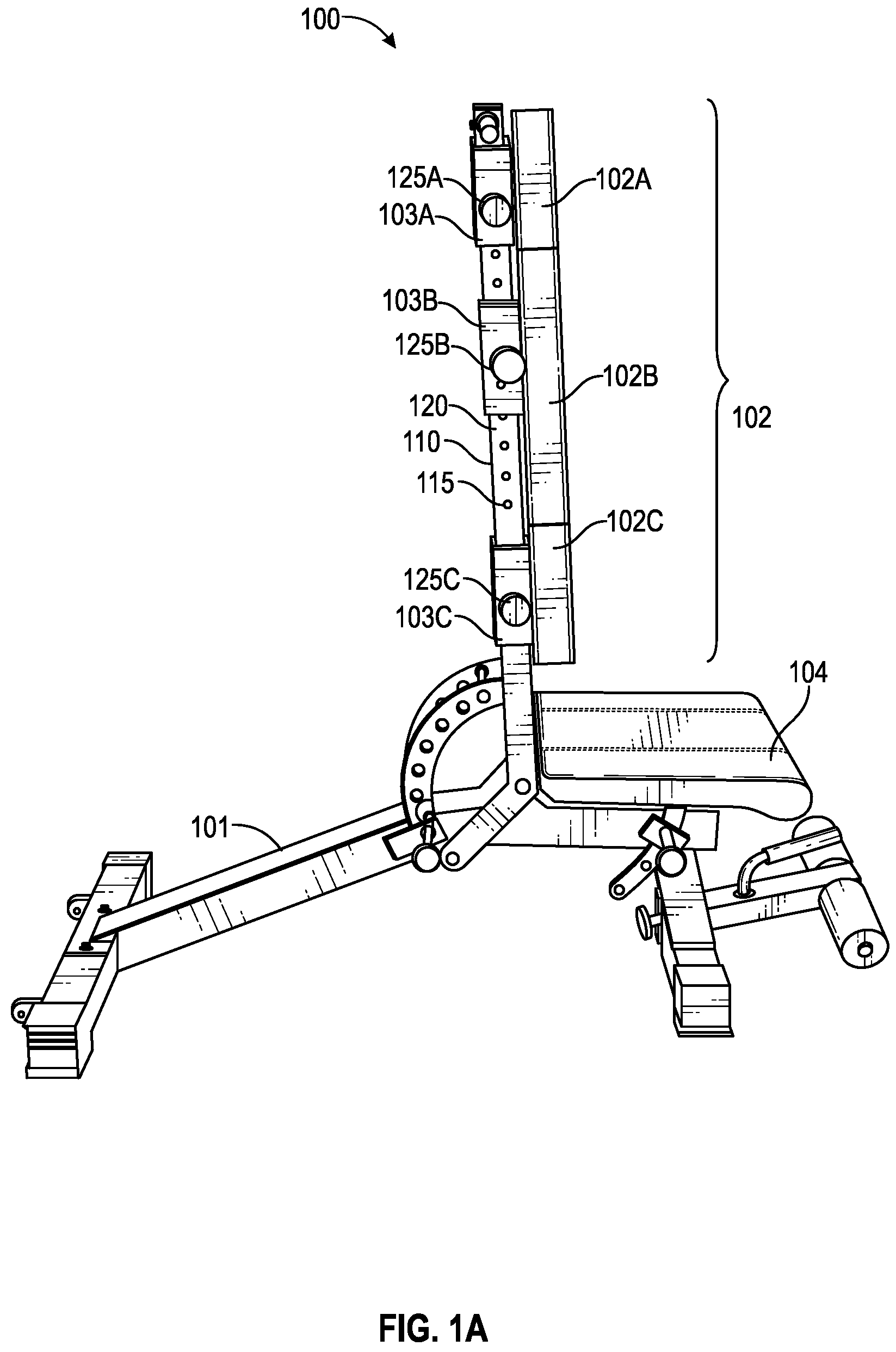
A- 1 B illustrate an exercise bench 100 in accordance with an embodiment. As shown, the exercise bench 100 can include a basal frame 101 . A seat 104 is attached to the basal frame 101 . The seat 104 can include a pad. The height of the seat 104 can be adjusted (for example, moved between 0 degrees to 30 degrees) depending on a user's requirements. A mounting bar 120 can be coupled to the basal frame 101 . The mounting bar 120 can include a central opening and a plurality of pre-drilled holes along a sidewall or opposing sets of holes/through holes 115 along at least two side surfaces/sidewalls.
A backrest assembly 102 can be integrated with or coupled to the basal frame 101 . In an embodiment, the mounting bar 120 can be mounted vertically to the basal frame 101 . The backrest assembly 102 further comprises a carriage assembly 110 (further described with reference to A- 2 B, 3 A- 3 B, and 4 A- 4 B ).
Conventional exercise benches have a one-piece backrest which is configured to support the user's back and head. The backrest of conventional adjustable benches can be inclined or reclined but the overall height of the backrest cannot be adjusted or changed based on the user's height. Advantageously, the backrest assembly 102 comprises multiple segments, for example, at least one headrest segment or piece/unit/part and one or more backrest segment or pieces/units/parts. For example, the backrest assembly 102 can include a headrest 102 A and at least a first backrest segment 102 B and a second backrest segment 102 C. Each segment can be configured to be movable or adjustable to accommodate users having varying heights or for user comfort. For example, as shown in B , headrest 102 A and backrest segments 102 B- 102 C can be moved along a vertical plane, that is the headrest and backrest segments 102 A- 102 C can be moved upward and downward along the mounting bar 120 .
As shown in A and 2 B , the backrest assembly 102 can include multiple distinct segments 102 A, 102 B, 102 C. For example, the backrest assembly 102 has a headrest 102 A, a first backrest segment 102 B and a second backrest segment 102 C, wherein each segment is separated from the adjacent segment. The headrest segment 102 A is designed to substantially support the head of the user while each backrest segment 102 B, 102 C are designed to substantially support a portion of the back of the user. The headrest segment 102 A and the backrest segments 102 B, 102 C can each be moved upward or downward along the mounting bar 120 using corresponding carriage members 103 A, 103 B, and 103 C (as shown in A- 1 B and 2 A ). In an example, the second backrest segment 102 C can be moved or slided toward or away from the seat 104 . In one or more embodiments, the seat 104 can also be moved or slided toward or away from the second backrest segment 102 C such that any gap between the second backrest segment 102 C and the seat 104 is decreased or increased. It is understood that the shape and other dimensions, such as, the height and width, of the multiple segments 102 A, 102 B, and 102 C can be changed/varied and all such variations are within the scope of the invention.
Each adjacent surface of the multiple segments 102 A, 102 B, 102 C can be sized and shaped for a substantially close sliding reception. As shown in B and 2 B , the segments 102 A- 102 C are capable of selective upward and downward movement along the mounting bar 120 when their corresponding carriage members 103 A- 103 C are moved upward or downward by a user (not shown). In one or more embodiments, the carriage members described herein are tubular members having sidewalls and a central cavity.
The segments 102 A, 102 B, and 102 C and seat 104 can be padded or have cushions. The pads/cushions can be made of any suitable material that is firm but also allows for a comfortable workout experience for the user.
It is understood that the segments 102 A, 102 B, and 102 C can have any suitable shape and size. Furthermore, in one or more embodiments (not shown), an additional component (not shown) can be used in between the headrest and the backrest segments (and between the lowermost backrest segment and the seat) to ensure a smoother profile when the segments are moved closer to each other.
A- 2 B illustrate a carriage assembly 110 for the exercise bench 100 in accordance with an embodiment. The carriage assembly 110 can include carriage members 103 A, 103 B, 103 C affixed or otherwise coupled to a back surface of the headrest 102 A and backrest segments 102 B, 102 C. In an example, the carriage assembly 110 can have a first carriage member 103 A coupled to a back surface of the headrest 102 A, a second carriage member 103 B coupled to a back surface of the first backrest segment 102 B, and a third carriage member 103 C coupled to a back surface of the second backrest segment 102 C. Each carriage member 103 A- 103 C includes a central opening. The mounting bar 120 can be inserted through the central opening of each of the carriage members. The carriage members 103 A, 103 B, 103 C are made of a suitable durable and sturdy material, such as, steel or other suitable materials. The carriage members 103 A, 103 B, 103 C can be substantially tubular, square or rectangular-shaped members. In one example, the carriage members 103 A- 103 C can be brackets. As mentioned earlier, each carriage member can include one or more sets of holes (not shown). The holes on the carriage member are designed to receive a corresponding connector 125 A- 125 C.
The mounting bar 120 can be cylindrical, columnar or cuboid. The mounting bar 120 can include a plurality of pre-drilled sets of holes 115 drilled along its sidewalls. In one or more embodiments, the holes 115 can be through holes so the brackets can be reversed and accessible from either side of the mounting bar 120 . Each set of holes 115 can be spaced apart substantially equidistant from an adjacent set of holes. In an embodiment, each set of holes 115 may be optionally separated by one inch or one-half inch from an adjacent set of holes.
Each carriage member 103 A, 103 B, 103 C has at least one opening (not shown) on a sidewall or a set of opposing openings/holes on opposing sidewalls for receiving a connector. For example, the first carriage member 103 A has an opening or a set of openings for receiving a first connector 125 A, the second carriage member 103 B has an opening or a set of openings for receiving a second connector 125 B, and the third carriage member 103 C has an opening or a set of openings for receiving a third connector 125 C. The connectors 125 A, 125 B, 125 C are configured to fasten or lock the corresponding carriage members at a desired height/position on the mounting bar 120 . The connectors 125 A, 125 B, 125 C can include, without limitations, any conventional fastener, such as, a screw, bolt, securing pin, pin pop-pins or removable pins known in the art. In one or more embodiments, other conventional securing means, such as clamps, can be used to lock the carriage members 103 A, 103 B, 103 C in position at a desired height on the mounting bar 120 .
The connectors 125 A, 125 B, 125 C can also include a rotatable knob. When the connectors are loosened by rotating them in a first direction (for example, a clockwise direction), the carriage members 103 A, 103 B, 103 C can be moved up or down the mounting bar 120 . The carriage members can be locked in position at a desired height by rotating the connectors 125 A, 125 B, 125 C in a second direction (for example, a counterclockwise direction). Depending on the user's requirements, each carriage member can be moved up or down the mounting bar 120 and secured within a hole 115 at a desired height independently. In another embodiment, the connectors are configured without a rotatable knob. In this and other embodiments, the connectors can secure the carriage members in position at a desired height without an additional locking or securing mechanism.
As shown in A- 2 B and 3 B , the headrest segment 102 A and the first backrest segment 102 B can be moved such that there is a first space or gap 130 A between the two pads. Similarly, the first backrest segment 102 B and the second backrest segment 102 C can be moved such that there is a second space or gap 130 B between the two segments.
In use, the user can move the headrest 102 A upward (or downward) by loosening the first connector 125 A coupling the first carriage member 103 A to the mounting bar 120 . For example, the first connector can be rotated in a first direction to loosen it. After the headrest is loosened, it can be moved to a desired height and one or a set of holes/openings (not shown) in the first carriage member 103 A is aligned with a corresponding hole or set of holes 115 A in the mounting bar 120 , and the connector 125 A is inserted through the aligned holes. The first connector 125 A can tightly secure the first carriage member 103 A to the mounting bar 120 (for instance, by rotating the first connector in a second direction). In this manner, the headrest 102 A is substantially immovably secured to the mounting bar. Similarly, the backrest segments 102 B, 102 C can be moved upward or downward and secured in position using a second and third connector 125 B and 125 C respectively. The second and third carriage members 103 B and 103 C can be aligned with corresponding holes or set of holes 115 B and 115 C in the mounting bar 120 respectively.
As needed, the headrest and backrest segments 102 A- 102 C can also be moved close to each other such that the bottom surface of the headrest 102 A contacts or abuts an upper surface of the first backrest segment 102 B and the bottom surface of the first backrest segment 102 B contacts or abuts an upper surface of the second backrest segment 102 C to form a substantially mated backrest/headrest combination unit. Thus, the user of the exercise bench 100 can adjust the height(s) of the headrest and/or backrest segments to fit their own height or exercise requirements. The headrest segment 102 A and the backrest segments 102 B, 102 C can further facilitate safety, comfort and proper form as the user can adjust their body into a position allowing for stability (such as, feet flat on the floor and/or head not hanging off the end of the bench).
The exercise bench 100 can further include a mechanism for inclining or declining the headrest and segmented backrest. Any conventional mechanism known in the art can be used for inclining/declining the headrest and backrest.
It is understood that the headrest segment 102 A, first backrest segment 102 B, and second backrest segment 102 C are configured for independent upward and downward slidable movement along the mounting bar 120 . As such, each segment can move independently or be stationary depending on the desired positions of the segments.
A- 3 B and 4 A- 4 B illustrate a carriage assembly 310 , 410 for an exercise bench in accordance with another embodiment. The backrest assemblies 302 and 402 have carriage members 303 A, 403 A. The carriage members 303 A, 403 A can be attached to or otherwise coupled to a back surface of a headrests 302 A, 402 A along a first end. Unlike the first carriage member 103 A, a second end of the carriage members 303 A and 403 A can be configured for slidable insertion inside or within a hollow cavity in the mounting bar 120 (as opposed to the mounting bar being inserted within an opening in the carriage member). The carriage members 303 A, 403 A can then be connected securely to the mounting bar using connectors 325 A, 425 A. Advantageously, by adjusting the height of the carriage member 303 A, 403 A (that is, by moving the carriage members 303 A, 403 A upward or within the mounting bar 120 , as required), the user can adjust the height of the headrests 302 A, 402 A by itself without having to make any corresponding adjustments to the heights of the backrest segments 302 B, 302 C or unsegmented backrest 402 B. Additionally, this arrangement also provides the user the option to extend the height of the headrest up to several inches beyond the height of the mounting bar 120 . Once the headrests 302 A, 402 A are moved to a desired height, the user can securely couple the carriage members 303 A, 403 A to the mounting bar 120 using connectors 325 A, 425 A.
The carriage members 303 A, 403 A can be dimensioned to slide within or fitted inside the mounting bar 120 . The carriage members 303 A, 403 A can be cylindrical, columnar or cuboid. The width and depth of the carriage members 303 A, 403 A can be smaller than the width and depth of the mounting bar 120 .
Now referring back to A- 3 B , the backrest assembly 302 also has a segmented backrest. As shown, the backrest 302 can include at least two slidable backrest segments 302 B, 302 C. The back surface of the backrest 302 B can be coupled to a second carriage member 303 B using connector 325 B while a back surface of the second backrest segment 302 C can be coupled to a third carriage member 303 C. In one or more embodiments, the carriage member 303 A is longer than the second and third carriage members 303 B, 303 C.
The first carriage member 303 A can include a plurality of pre-drilled holes/openings or sets of holes 315 drilled along its sidewalls. In one or more embodiments, the openings 315 can be through holes so the brackets can be reversed and accessible from either side of the first carriage member 303 A. Each opening 315 can be spaced apart substantially equidistant from an adjacent hole. In an embodiment, each opening 315 may be separated by one inch or one-half inch from an adjacent through hole. However, each of the openings need not be spaced apart at a substantially equal distance from an adjacent opening.
The headrest 302 A and the first backrest segment 302 B can be moved such that there is a first space or gap 330 A between the two pads. Similarly, the first backrest segment 302 B and the second backrest segment 302 C can be moved such that there is a second space or gap 330 B between the two segments.
All other features of this embodiment are similar to those disclosed earlier with reference to A- 2 B , and not repeated for brevity.
The mounting bar 120 is configured to be securely mounted within a central opening in the second carriage member 303 B and the third carriage member 303 C. A second and third connector 325 B, 325 C can be used to secure the mounting bar to the second and third carriage members 303 B, 303 C respectively. The height of the backrest segments 302 B, 302 C can be adjusted by removing the corresponding connectors 325 B, 325 C from the mounting bar 120 , moving these segments to a desired height and then tightening the corresponding connectors.
Similarly to the embodiment discussed in reference to A and 1 B , each adjacent surface of the multiple segments 302 A, 302 B, 302 C are sized and shaped for a substantially close sliding reception. The user (not shown) can move the headrest segment 302 A and backrest segments 302 B, 302 C close together, as needed, such that the bottom of the adjacent surface of the headrest segment 302 A contacts or abuts the surface of the first backrest segment 302 B to form a substantially joined backrest assembly 302 .
In another embodiment, shown in A- 4 B , the backrest is unsegmented 402 B. Similar to the embodiment described under A- 3 B , the headrest segment 402 A has a carriage member 403 A that is configured for insertion into the mounting bar 120 . The carriage member 403 A can be dimensioned to fit within the mounting bar 120 .
The back surface of the unsegmented backrest 402 B can be coupled to a second carriage member 403 B using connector 425 B. The headrest 402 A and the unsegmented backrest 402 B can be moved such that there is a space or gap 430 between the two pads.
The exercise bench according to one or more embodiments is adjustable, wherein the headrest and backrest (including two or more segments of the backrest) are all configured to be movable or adjustable in a vertical plane, that is, they can be moved upward and downward.
In one or more embodiments, the carriage members may be motorized for convenience.
While the foregoing describes various embodiments of the invention, other and further embodiments of the invention may be devised without departing from the basic scope thereof. The scope of the invention is determined by the claims that follow. The invention is not limited to the described embodiments, versions, or examples, which are included to enable a person having ordinary skill in the art to make and use the invention when combined with information and knowledge available to the person having ordinary skill in the art.
Figures (6)
Citations
This patent cites (20)
- US6152866
- US7044898
- USD541893
- US7674215
- US8206272
- US8968162
- US11925829
- US11938368
- US20010018387
- US20070129225
- US20070149373
- US20110195822
- US20160089558
- US20160213968
- US20170216656
- US20180099176
- US20180369633
- US20190151699
- US20200360764
- US20230337829