Image Display Device and Control Method Thereof
Abstract
An image display device is provided. The image display device includes a display unit and a backlight module. The display unit is used for displaying pictures in an image frame cycle. The backlight module includes a plurality of light sources of different colors. The image frame cycle is divided into a first interval, a second interval and a third interval in sequence, and the second interval is adjacent to the first interval. The backlight module provides a white light source with a first intensity in the first interval and provides a white light source with a second intensity in the second interval, and the second intensity is smaller than the first intensity. The backlight module is turned off in the third interval.
Claims (12)
1. An image display device, comprising: a display unit, for displaying pictures in an image frame cycle; and a backlight module, comprising a plurality of light sources of different colors, wherein, the image frame cycle is divided into a first interval, a second interval and a third interval in sequence, the second interval is adjacent to the first interval, the backlight module provides a single white light source with a first intensity in the first interval and provides the single white light source with a second intensity in the second interval, the second intensity is smaller than the first intensity, the duration length of the second interval is greater than the duration length of the sustained time of a red afterimage of the backlight module after the first interval so as to cover the red afterimage and eliminate a red-afterimage-phenomenon, wherein the magnitude of the second intensity gradually decreases in a stepped manner in the second interval, and the second intensity has a predefined ratio less than 0.5 with respect to the first intensity, and the second interval has an adjustable ratio with respect to the first interval, and the backlight module is turned off in the third interval.
6. A control method of an image display device, comprising: dividing an image frame cycle of a display unit into a first interval, a second interval and a third interval in sequence, wherein the second interval is adjacent to the first interval; in the first interval, controlling a backlight module to provide a single white light source with a first intensity to the display unit; in the second interval, controlling the backlight module to provide the single white light source with a second intensity to the display unit, wherein the second intensity is smaller than the first intensity; controlling the duration length of the second interval as being greater than the duration length of the sustained time of a red afterimage of the backlight module after the first interval so as to cover the red afterimage and eliminate a red-afterimage-phenomenon, wherein the magnitude of the second intensity gradually decreases in a stepped manner in the second interval, and the second intensity has a predefined ratio less than 0.5 with respect to the first intensity, and the second interval has an adjustable ratio with respect to the first interval; and in the third interval, turning off the backlight module.
11. An image display device, comprising: a display unit, for displaying pictures in an image frame cycle, the image frame cycle having a first interval and a third interval; and a backlight module, comprising a plurality of light sources of different colors, for providing a single white light source with a first intensity to the display unit in the first interval, and the backlight module is turned off in the third interval, wherein, the image frame cycle further includes a second interval and a fourth interval, the second interval and the fourth interval are between the first interval and the third interval, the second interval is adjacent to the first interval and the fourth interval is adjacent to the second interval, the backlight module provides the single white light source with a second intensity in the second interval, the second intensity is smaller than the first intensity, and the duration length of the second interval is greater than the duration length of the sustained time of a red afterimage of the backlight module after the first interval, and the backlight module provides the single white light source with a third intensity in the fourth interval, the third intensity is smaller than the second intensity, and the duration length of the fourth interval is greater than the duration length of the sustained time of a red afterimage of the backlight module after the second interval, so as to cover the red afterimages after the first interval and the second interval and eliminate a red-afterimage-phenomenon, wherein the magnitude of the second intensity gradually decreases in a stepped manner in the second interval, and the second intensity has a predefined ratio less than 0.5 with respect to the first intensity, and the second interval has an adjustable ratio with respect to the first interval.
Show 9 dependent claims
2. The image display device according to claim 1 , wherein the image frame cycle further includes a fourth interval, the fourth interval is between the second interval and the third interval, the fourth interval is adjacent to the second interval, and the backlight module provides the single white light source with a third intensity in the fourth interval, the third intensity is smaller than the second intensity.
3. The image display device according to claim 2 , the duration length of the fourth interval is greater than the duration length of the sustained time of a red afterimage of the backlight module after the second interval.
4. The image display device according to claim 2 , further comprising: a backlight control unit, for generating a first driving signal according to a vertical synchronization signal, and providing the first driving signal to the backlight module, wherein, the vertical synchronization signal updates the image frame cycle, and the backlight module respectively provides the single white light source with the first intensity, the second intensity and the third intensity according to the current value of the first driving signal.
5. The image display device according to claim 1 , wherein the magnitude of the second intensity gradually decreases in the second interval.
7. The control method according to claim 6 , further comprising: further dividing the image frame cycle into a fourth interval, the fourth interval is between the second interval and the third interval, and the fourth interval is adjacent to the second interval; and in the fourth interval, controlling the backlight module to provide the single white light source with a third intensity to the display unit, wherein the third intensity is smaller than the second intensity.
8. The control method according to claim 7 , further comprising: controlling the duration length of the fourth interval as being greater than the duration length of the sustained time of a red afterimage of the backlight module after the second interval.
9. The control method according to claim 7 , further comprising: controlling a backlight control unit to generate a first driving signal according to a vertical synchronization signal, wherein the vertical synchronization signal updates the image frame cycle; providing the first driving signal to the backlight module; and controlling the backlight module to respectively provide the single white light source with the first intensity, the second intensity and the third intensity according to the current value of the first driving signal.
10. The control method according to claim 6 , further comprising: controlling the magnitude of the second intensity as gradually decreasing in the second interval.
12. The image display device according to claim 11 , further comprising: a backlight control unit, for providing a first driving signal to the backlight module according to a vertical synchronization signal, wherein, the vertical synchronization signal updates the image frame cycle, and the backlight module respectively provides the single white light source with the first intensity, the second intensity and the third intensity according to the current value of the first driving signal.
Full Description
Show full text →
This application claims the benefit of People's Republic of China application Serial No. 202111331873.7, filed Nov. 11, 2021, the subject matter of which is incorporated herein by reference.
TECHNICAL FIELD
The present disclosure relates to an electronic device and a control method thereof, and more particularly, relates to an image display device and a control method for suppressing backlight afterimages.
BACKGROUND
Due to the characteristic of visual persistence of human visual perception, when the image frame of the display is updated, afterimage of previous image frame may interfere with visual perception of the current image frame, resulting in dragging of picture of display and causing motion blur.
In order to improve the phenomenon of motion blur, the display may support a mechanism of “moving picture response time (MPRT)” to insert a black image frame between normal image frames, referred to as an operation of “black frame insertion (BFI)”. Alternatively, the backlight module may be turned off between intervals of displaying normal image frames, so as to simulate the operation of black frame insertion.
When simulating the operation of black frame insertion, although the backlight module has been turned off and stops providing backlight, however, due to characteristic of visual persistence, the backlight before the backlight module is turned off may still cause afterimages. The red afterimage of red light source has the longest duration length and interferes with visual perception seriously. Traditionally, color gamut range of phosphor powder of backlight sources with various colors is reduced, so as to change spectral components of red light source to reduce the red afterimage.
However, in order to change color gamut range of phosphor powder of backlight sources, hardware of the backlight module must be changed, which will consume more hardware costs. To address the aforementioned technical problems, skilled ones of related industries in the technical field of display are devoted to develop a more effective method, so that operation of black frame insertion may be simulated under MPRT, and red afterimages may be reduced.
SUMMARY
The present disclosure provides an image display device and an operation method thereof, which are used to control the backlight module of an image display device to provide backlights with different intensities in different intervals of an image frame cycle, so that afterimage of the image display device may be reduced.
According to an aspect of the present disclosure, an image display device is provided. The image display device includes a display unit and a backlight module. The display unit is used for displaying pictures in an image frame cycle. The backlight module includes a plurality of light sources of different colors. The image frame cycle is divided into a first interval, a second interval and a third interval in sequence, the second interval is adjacent to the first interval, the backlight module provides a white light source with a first intensity in the first interval and provides a white light source with a second intensity in the second interval, the second intensity is smaller than the first intensity, and the backlight module is turned off in the third interval.
According to another aspect of the present disclosure, an image display device is provided. The image display device includes a display unit and a backlight module. The display unit is used for displaying pictures in an image frame cycle, and the image frame cycle has a first interval and a third interval. The backlight module includes a plurality of light sources of different colors, the backlight module is used for providing a white light source with a first intensity to the display unit in the first interval, and the backlight module is turned off in the third interval. The image frame cycle further includes a second interval and a fourth interval, the second interval and the fourth interval are between the first interval and the third interval, the second interval is adjacent to the first interval and the fourth interval is adjacent to the second interval, the backlight module provides a white light source with a second intensity in the second interval, the second intensity is smaller than the first intensity, and the backlight module provides a white light source with a third intensity in the fourth interval, the third intensity is smaller than the second intensity.
According to still another aspect of the present disclosure, a control method of an image display device is provided. The control method includes the following steps. Dividing an image frame cycle of a display unit into a first interval, a second interval and a third interval in sequence, wherein the second interval is adjacent to the first interval. In the first interval, a backlight module is controlled to provide a white light source with a first intensity to the display unit. In the second interval, the backlight module is controlled to provide a white light source with a second intensity to the display unit, wherein the second intensity is smaller than the first intensity. In the third interval, the backlight module is turned off.
BRIEF DESCRIPTION OF THE DRAWINGS
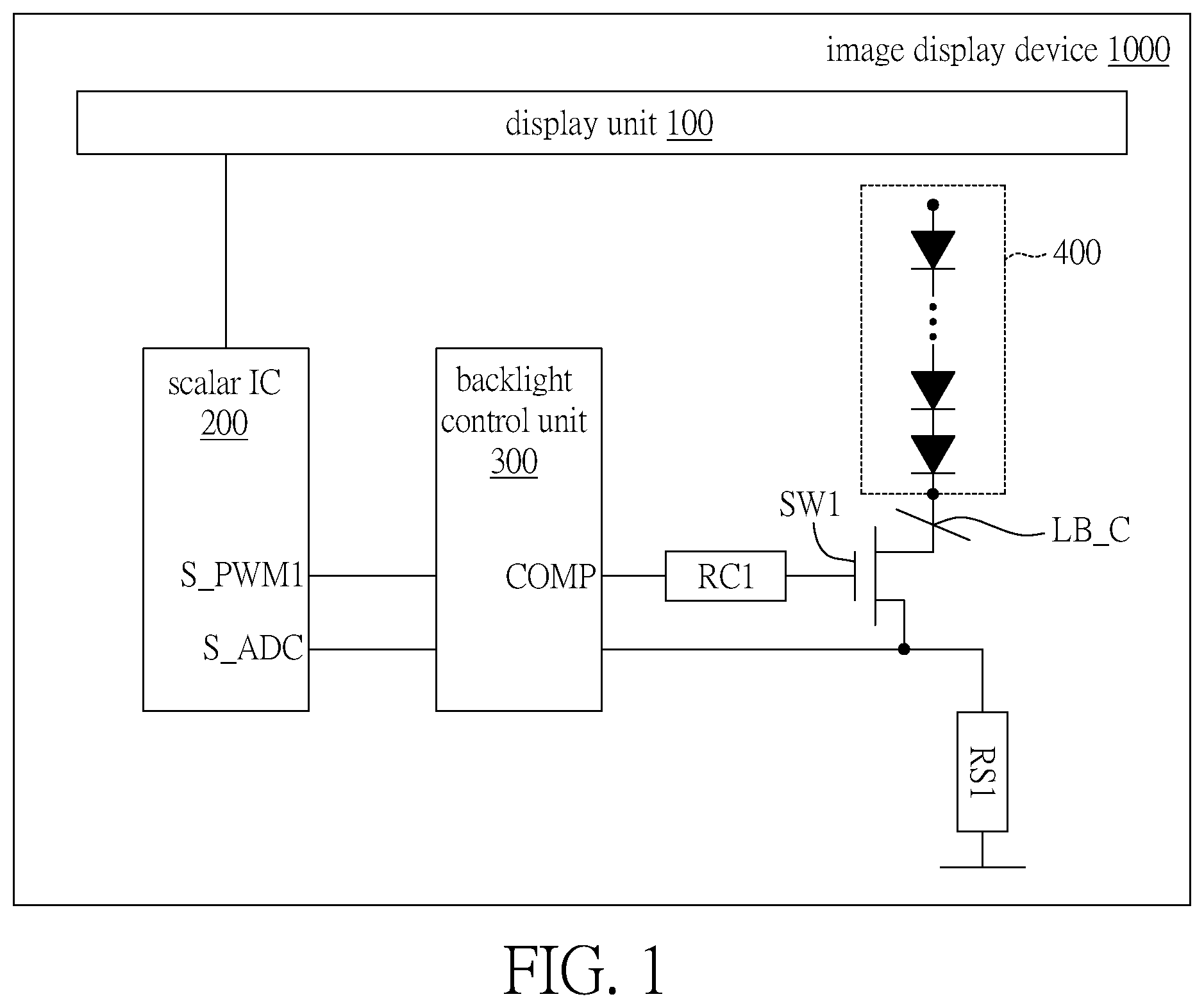
is a block diagram of an image display device according to an embodiment of the present disclosure.
is a timing diagram of each control signal of the image display device according to an embodiment of the present disclosure.
A- 3 D are schematic diagrams of afterimages of the backlight module.
is a timing diagram illustrating backlight control of the backlight module according to an embodiment of the present disclosure.
is a timing diagram illustrating backlight control of the backlight module according to another embodiment of the present disclosure.
A- 6 C are timing diagrams illustrating backlight control of the backlight module according to another three embodiments of the present disclosure.
A and 7 B are timing diagrams of each control signal of the image display device corresponding to the embodiments of A and 6 B .
is a flow diagram of a control method of the image display device according to an embodiment of the present disclosure.
In the following detailed description, for purposes of explanation, numerous specific details are set forth in order to provide a thorough understanding of the disclosed embodiments. It will be apparent, however, that one or more embodiments may be practiced without these specific details. In other instances, well-known structures and devices are schematically illustrated in order to simplify the drawing.
DETAILED DESCRIPTION
is a block diagram of an image display device 1000 according to an embodiment of the present disclosure. Referring to , the image display device 1000 includes a display unit 100 , a scalar IC 200 , a backlight control unit 300 and a backlight module 400 . The image display device 1000 is, for example, an external screen of a desktop computer or a built-in screen of a laptop computer, and may also be a display screen of a home TV or a display screen of a video wall of a commercial exhibition hall. The display unit 100 is a display panel of the image display device 1000 . The display unit 100 has a plurality of pixels, and these pixels may form a whole picture.
Please also refer to , which is a timing diagram of each control signal of the image display device 1000 according to an embodiment of the present disclosure. In operation, the display unit 100 defines an image frame cycle according to a vertical synchronization signal Vsync and updates the image frame according to the vertical synchronization signal Vsync. Accordingly, the display unit 100 displays a picture of the corresponding image frame in each image frame cycle. For example, the picture of the first image frame is displayed in the first image frame cycle Fc 1 , and the picture of the second image frame is displayed in the second image frame cycle Fc 2 , and so on. In one example, the display updating frequency of the display unit 100 is 80 fps, i.e., 80 image frames are displayed per second. In other words, the duration length of each image frame cycle is 1/80 second (i.e., 0.0125 seconds). In the operating schemes of the display unit 100 , each image frame cycle may be further divided into at least a first interval T 1 , a second interval T 2 and a third interval T 3 in sequence. The display unit 100 may display a normal picture including video content in the first interval T 1 .
Please refer to again, the backlight module 400 is, for example, a backlight plate of the image display device 1000 . The backlight module 400 may dispose a plurality of light emitting diodes (LED) or micro light emitting diodes (micro LED) to form a plurality of light sources (i.e., backlight sources), thereby providing the backlight of the image display device 1000 . Moreover, these light sources have different colors, such as red light sources, blue light sources and green light sources. The red light sources, blue light sources and green light sources may be mixed as white light sources. In the operating scheme of the backlight module 400 , as shown in , when the display unit 100 displays a normal picture in the first interval T 1 , the backlight module 400 correspondingly provides a white light source in the first interval T 1 . That is, the backlight module 400 entirely turns on the red light source, blue light source and green light source, and the three types of light sources are mixed as the white light source.
On the other hand, the scalar IC 200 and the backlight control unit 300 may provide a plurality of control signals or driving signals to control the operation of the backlight module 400 . In this embodiment, the scalar IC 200 may provide a first control signal S_PWM 1 and a second control signal S_ADC to the backlight control unit 300 , and the backlight control unit 300 may correspondingly generate a third control signal COMP. The third control signal COMP may be further converted to a first driving signal LB_C through the circuit element RC 1 and the transistor SW 1 , and the first driving signal LB_C is used to drive the backlight module 400 . As shown in , in the first interval T 1 , the first control signal S_PWM 1 and the second control signal S_ADC are both in an enable state (e.g., a state of high voltage level). Correspondingly, the third control signal COMP is also in the enable state (not shown in ). Accordingly, the first driving signal LB_C of the enable state may be provided to drive the backlight module 400 . In this embodiment, the first driving signal LB_C is a driving current, and the backlight module 400 may adjust the intensity of the light sources according to the current value of the first driving signal LB_C. For example, the current value I 1 of the first driving signal LB_C generates a white light source with a first intensity L 1 .
However, the white light source may have an afterimage after the first interval T 1 , as shown in the schematic diagrams of the afterimages of the backlight module 400 in A- 3 D . The white light source W 1 in the first interval T 1 has a red light component R 1 , a blue light component B 1 and a green light component G 1 . The red light component R 1 has a red afterimage R 2 after the first interval T 1 , and the duration length of the red afterimage R 2 is TR. Furthermore, the blue light component B 1 has a blue afterimage B 2 with a duration length of TB. Moreover, the green light component G 1 has a green afterimage G 2 with a duration length of TG. More particularly, the red light sources, blue light sources and green light sources of the backlight module 400 may be realized by, for example, red light diodes, blue light diodes and green light diodes. The above-mentioned colorful diodes use phosphor powders of different colors. Different colors of phosphor powders have different response times in human visual perception, wherein the response time of red phosphor powders is the longest. Therefore, the red afterimage R 2 of the red light component R 1 has the longest duration length TR (i.e., the duration length TR of the red afterimage R 2 is greater than the duration length TG of the green afterimage G 2 and the duration length TB of the blue afterimage B 2 ). Therefore, for human visual perception, the red afterimage R 2 is the most significant, which is referred to as “red afterimage phenomenon”. The technical solution of the present disclosure refers to control backlight of the backlight module 400 by software or firmware so as to suppress or eliminate the above-mentioned red afterimage phenomenon.
Please refer to , which shows a timing diagram of backlight control of the backlight module 400 according to an embodiment of the present disclosure. In the backlight control mechanism of the present embodiment, the backlight module 400 is controlled to continuously provide a white light source after the first interval T 1 to shield or cover the red afterimage R 2 . Specifically, in the second interval T 2 adjacent to the first interval T 1 (the second interval T 2 is after the first interval T 1 ), the backlight module 400 may provide a white light source W 2 with the second intensity L 2 (that is, the duration length of the white light source W 2 is equal to the duration length of the second interval T 2 ) so as to shield or cover the red afterimage R 2 . Compared with the white light source W 1 in the first interval T 1 , the second intensity L 2 of the white light source W 2 in the second interval T 2 is smaller (i.e., the second intensity L 2 is smaller than the first intensity L 1 ). Moreover, the duration length of the white light source W 2 (i.e., the duration length of the second interval T 2 ) is at least greater than the duration length TR of the red afterimage R 2 . Therefore, for human visual perception, the white light source W 2 may effectively shield or cover the red afterimage R 2 and eliminate the red afterimage phenomenon.
Next, a “Moving Picture Response Time (MPRT)” mode of the display is supported, and the backlight module 400 is turned off in the third interval T 3 (which is after the second interval T 2 and adjacent to the second interval T 2 ) to simulate an operation of black frame insertion, thereby suppressing motion blur of the display unit 100 .
The above-described embodiments may be applied to each image frame cycle. For example, in the second interval T 2 of the first image frame cycle Fc 1 , the backlight module 400 provides a white light source W 2 with a second intensity L 2 to cover the red afterimage R 2 . Based on the same implementation, the white light source W 2 of the second intensity L 2 is also provided in the second interval T 2 of the second image frame cycle Fc 2 , and so on. Referring to again, in order to control and drive the backlight module 400 to provide white light sources with a first intensity L 1 and a second intensity L 2 in the first interval T 1 and the second interval T 2 respectively, the second control signal S_ADC of the scalar IC 200 in the second interval T 2 has a voltage level lower than the voltage level in the first interval T 1 , so that the current value I 2 of the first driving signal LB_C of the backlight control unit 300 in the second interval T 2 is smaller than the current value I 1 in the first interval T 1 . Furthermore, the current value of the first driving signal LB_C is substantially reduced to zero in the third interval T 3 , so as to turn off the backlight module 400 .
is a timing diagram illustrating backlight control of the backlight module 400 according to another embodiment of the present disclosure (only one image frame cycle Fc 1 is shown). Referring to , the second intensity L 2 ′ of the white light source W 2 in this embodiment may be smaller than the second intensity L 2 of the white light source W 2 in . In addition, the duration length of the white light source W 2 in this embodiment (i.e., the duration length of the second interval T 2 ′) may be smaller than the duration length of the white light source W 2 of (i.e., the duration length of the second interval T 2 ). That is, in this embodiment, the intensity and duration length of the white light source W 2 are reduced, so that the white light source W 2 has a smaller profile, but can still cover the red afterimage R 2 .
For example, in the first interval T 1 , the current value I 1 of the first driving signal LB_C for generating the white light source W 1 is 106 mA, so that the white light source W 1 has the first intensity L 1 . The ratio of duration length of the white light source W 1 (i.e., duration length of the first interval T 1 ) to the entire image frame cycle Fc 1 is 31.9%. Correspondingly, in the second interval T 2 ′, the current value I 2 ′ of the first driving signal LB_C is set as 15 mA, so that the white light source W 2 has the first intensity L 2 ′. The ratio of duration length of the white light source W 2 (i.e., duration length of the second interval T 2 ′) is set as 19.2%. Under the above-mentioned settings for intensity and duration length, the white light source W 2 in the second interval T 2 ′ can still substantially cover the red afterimage R 2 .
In this embodiment, even though the white light source W 2 in the second time interval T 2 ′ still has a red afterimage R 3 , the intensity of the white light source W 2 has been reduced to a smaller value of second intensity L 2 ′. The red afterimage R 3 generated by the white light source W 2 has reduced intensity and duration length, hence human visual perception is less affected.
As described above, in the embodiments shown in , after the first interval T 1 the backlight module 400 provides white light source with constant intensity, for example, the intensity of the white light source W 2 is a constant value of second intensity L 2 (or second intensity L 2 ′). On the other hand, since the intensity of the red afterimage R 2 , the blue afterimage B 2 and the green afterimage G 2 is gradually decreasing, the red afterimage can be substantially covered by providing white light source W 2 with decreasing intensity. A- 6 C are timing diagrams illustrating backlight control of the backlight module 400 according to another three embodiments of the present disclosure. First, please refer to A , the second intensity L 2 of the white light source W 2 may gradually decrease in the second interval T 2 . For example, the second intensity L 2 decreases from the first intensity L 1 to zero in a ramp-down manner (i.e., ramped decrease). On the other hand, referring to B , the second intensity L 2 of the white light source W 2 may decrease to the third intensity L 3 in a stepped manner (i.e., stepped decrease) in the second interval T 2 .
The embodiment of B may also be represented as the aspect of C . As shown in C , the image frame cycle Fc 1 may be further divided into a fourth interval T 4 . The fourth interval T 4 is between the second interval T 2 and the third interval T 3 , and the fourth interval T 4 is adjacent to the second interval T 2 . The backlight module 400 provides the white light source W 2 during the second interval T 2 and provides the white light source W 3 during the fourth interval T 4 . In other words, the embodiment of C further divides the white light source into a white light source W 2 and a white light source W 3 to cover the red afterimages R 2 and R 3 respectively. Moreover, the third intensity L 3 of the white light source W 3 is smaller than the second intensity L 2 of the white light source W 2 . That is, the white light source W 2 decreases to the white light source W 3 in a stepped manner. Furthermore, the duration length of the white light source W 3 (i.e., the duration length of the fourth interval T 4 ) is at least greater than the duration length of the red afterimage R 3 after the second interval T 2 .
A and 7 B respectively illustrate timing diagrams of each control signal of the image display device 1000 corresponding to the embodiments of A and 6 B . For the backlight module 400 to control the second intensity L 2 of the white light source W 2 to decrease in a ramp-down manner in the second interval T 2 (the embodiment of A ), as shown in A , the scalar IC 200 has a second control signal S_ADC with a voltage level ramped decreasing in the second interval T 2 , and the current value I 2 of the first driving signal LB_C of the backlight control unit 300 also ramped decreases in the second interval T 2 .
On the other hand, for the backlight module 400 to control the second intensity L 2 of the white light source W 2 to decrease in a stepped manner in the second interval T 2 (as the embodiment of B ), as shown in B , the voltage level of the second control signal S_ADC of the scalar IC 200 and the current value I 2 of the first driving signal LB_C of the backlight control unit 300 also decrease in a stepped manner in the second interval T 2 .
is a flow diagram of a control method of the image display device 1000 according to an embodiment of the present disclosure. Referring to , in step S 110 , each image frame cycle of the display unit 100 of the image display device 1000 is sequentially divided into a first interval T 1 , a second interval T 2 and a third interval T 3 . The second interval T 2 is adjacent to the first interval T 1 . Then, in step S 120 , the backlight control unit 300 is controlled according to the vertical synchronization signal Vsync of the image display device 1000 , so to generate a first driving signal LB_C. The backlight module 400 is driven by the first driving signal LB_C. The intensity of the light source generated by the backlight module 400 may be controlled according to the current value of the first driving signal LB_C, so that the backlight module 400 may provide light sources with different intensities in different intervals of the image frame cycle.
Then, in step S 130 , the backlight module 400 of the image display device 1000 is controlled to provide the white light source W 1 , which has a first intensity L 1 , to the display unit 100 during the first interval T 1 . Then, in step S 140 , the backlight module 400 is controlled to provide the white light source W 2 , which has a second intensity L 2 , to the display unit 100 in the second interval T 2 . The second intensity L 2 is smaller than the first intensity L 1 . Then, in step S 150 , the intensity of the white light source W 2 is controlled and adjusted, so that the intensity of the white light source W 2 is constant (maintained as the second intensity L 2 ) or decreased in the second interval T 2 . It may have a ramped type of decreasing or a stepped type of decreasing.
In the examples of the stepped type of decreasing, the image frame cycle may be further divided into a fourth interval T 4 , which is between the second interval T 2 and the third interval T 3 . In addition, the backlight module 400 is controlled to provide the white light source W 3 in the fourth interval T 4 . The third intensity L 3 of the white light source W 3 is smaller than the second intensity L 2 . Accordingly, the white light source W 2 provided by the backlight module 400 decreases to form the white light source W 3 in a manner of stepped decreasing.
Then, in step S 160 , duration length of the white light source W 2 (i.e., duration length of the second interval T 2 ) is controlled and adjusted to be greater than duration length of the red afterimage R 2 of the backlight module 400 after the first interval T 1 . Accordingly, the white light source W 2 with the second intensity L 2 , which is provided in the second interval T 2 , can shield or cover the red afterimage R 2 , after the first interval T 1 . Hence, the red afterimage phenomenon may be suppressed or eliminated. Then, in step S 170 , the backlight module 400 is turned off to simulate the operation of black frame insertion.
On the other hand, for the examples where the white light source W 2 gradually decreases to form the white light source W 3 in a manner of stepped decreasing, duration length of the white light source W 3 (i.e., duration length of the fourth interval T 4 ) is also controlled. So that duration length of the white light source W 3 is greater than that of the red afterimage R 3 of the backlight module 400 after the second interval T 2 . Hence, the red afterimage R 3 is shielded or covered by the white light source W 3 .
From the above, in the image display device 1000 and the control method thereof according to the embodiments of the present disclosure, between the interval when the image display device 1000 displays a normal picture and the interval when the backlight module is turned off to simulate the operation of black frame insertion, white light sources with different intensities are provided (i.e., the brightness are segmented). Intensity of the white light source is controlled to be constant, ramped decreasing or stepped decreasing, so as to achieve segmented brightness. The white light source is used to cover afterimages of the normal picture, especially covering the red afterimage with the longest duration length, hence technical effect of suppressing or eliminating red afterimage phenomenon is achieved. The technical solution of the present disclosure needs not change the color gamut range of the backlight phosphor powders of the backlight module (i.e., needs not change hardware of the backlight module). Instead, the technical solution of the present disclosure only needs to control the backlight of the backlight module with software or firmware to suppress or eliminate red afterimage phenomenon.
It will be apparent to those skilled in the art that various modifications and variations can be made to the disclosed embodiments. It is intended that the specification and examples be considered as exemplary only, with a true scope of the disclosure being indicated by the following claims and their equivalents.
Figures (10)
Citations
This patent cites (5)
- US20050254509
- US20060208998
- US20100149435
- US20120256908
- US20160269697