Wireless Tag Reading Apparatus and Control Method for a Wireless Tag Reading Apparatus
Abstract
In accordance with an embodiment, a wireless tag reading apparatus includes an antenna, first and second power feeding ports, and a controller. The first power feeding port feeds electric power into the antenna so as to emit the first linearly polarized wave from the antenna. The second power feeding port feeds electric power into the antenna so as to emit the second linearly polarized wave from the antenna. The controller sets a ratio of a time of power feeding from the first power feeding port to a time of power feeding from the second power feeding port to take a value according to a ratio of the number of wireless tags existing in the direction of the first linearly polarized wave to the number of wireless tags existing in the direction of the second linearly polarized wave.
Claims (4)
1. A control method for a wireless tag reading apparatus configured to communicate with a wireless tag that stores information, the wireless tag reading apparatus including: an antenna capable of emitting a first linearly polarized wave having a first plane of polarization and a second linearly polarized wave having a second plane of polarization, the second plane of polarization having an orientation that is different from that of the first plane of polarization, and first and second power feeding ports to which electric power is supplied, the antenna emitting the first linearly polarized wave when the electric power is supplied to the first power feeding port and the second linearly polarized wave when the electric power is supplied to the second power feeding port, the control method comprising: determining a ratio of a first number of wireless tags that are responsive to the first linearly polarized wave to a second number of wireless tags that are responsive to the second linearly polarized wave; setting a ratio of a time of power feeding to the first power feeding port to a time of power feeding to the second power feeding port based on the determined ratio; switching between the power feeding to the first power feeding port and the power feeding to the second power feeding port in accordance with the set ratio; and upon receipt of a response wave that is corresponding to the first linearly polarized wave or the second linearly polarized wave via the antenna, reading the information of the wireless tag included in the response wave, wherein the setting includes setting, in accordance with the determined ratio, a first maximum bit length of a slot counter of each of the wireless tags responsive to the first linearly polarized wave and a second maximum bit length of a slot counter of each of the wireless tags responsive to the second linearly polarized wave.
3. A control method for a wireless tag reading apparatus configured to communicate with a wireless tag that stores information, the wireless tag reading apparatus including: an antenna capable of emitting a first linearly polarized wave having a first plane of polarization and a second linearly polarized wave having a second plane of polarization, the second plane of polarization having an orientation that is different from that of the first plane of polarization, and first and second power feeding ports to which electric power is supplied, the antenna emitting the first linearly polarized wave when the electric power is supplied to the first power feeding port and the second linearly polarized wave when the electric power is supplied to the second power feeding port, the control method comprising: determining a ratio of a first number of wireless tags that are responsive to the first linearly polarized wave to a second number of wireless tags that are responsive to the second linearly polarized wave; setting a ratio of a time of power feeding to the first power feeding port to a time of power feeding to the second power feeding port based on the determined ratio; switching between the power feeding to the first power feeding port and the power feeding to the second power feeding port in accordance with the set ratio; and upon receipt of a response wave that is corresponding to the first linearly polarized wave or the second linearly polarized wave via the antenna, reading the information of the wireless tag included in the response wave, wherein the setting includes setting, in accordance with the determined ratio, a number of times to repeat a first inventory round in which the first linearly polarized wave is emitted and a number of times to repeat a second inventory round in which the second linearly polarized wave is emitted.
Show 2 dependent claims
2. The control method according to claim 1 , wherein in a case where the first number of wireless tags is larger than the second number of wireless tags, the first maximum bit length is set to be longer than the second maximum bit length, and in a case where the second number of wireless tags is larger than the first number of wireless tags, the second maximum bit length is set to be longer than the first maximum bit length.
4. The control method according to claim 3 , wherein in a case where the first number of wireless tags is larger than the second number of wireless tags, the number of times to repeat the first inventory round is set to be larger than the number of times to repeat the second inventory round, and in a case where the second number of wireless tags is larger than the first number of wireless tags, the number of times to repeat the second inventory round is set to be larger than the number of times to repeat the first inventory round.
Full Description
Show full text →
CROSS-REFERENCE TO RELATED APPLICATION
This application is a division of U.S. patent application Ser. No. 17/070,833, filed on Oct. 14, 2020, which is based upon and claims the benefit of priority from the prior Japanese Patent Application No. 2020-004843, filed on Jan. 16, 2020, the entire contents of which are incorporated herein by reference.
FIELD
An embodiment described here generally relates to a wireless tag reading apparatus and a control method for a wireless tag reading apparatus.
BACKGROUND
In recent years, stock management, sales management, and the like of articles have been performed by reading information of wireless tags such as RFID tags attached to the articles. In general, since directions of provided wireless tags are unknown when reading the wireless tags, information of the wireless tags is read by emitting a circularly polarized wave capable of reading irrespective of the directions of the wireless tags.
However, the communicable distance of the circularly polarized wave is short. Therefore, if there is a need for securing a long communication distance, a linearly polarized wave having a longer communicable distance at the same radio wave intensity are used. For example, the wireless tags are read by switching between linearly polarized waves different in direction of polarization and using them.
However, if the directions of the provided wireless tags are unknown, it is also unknown how much time it should take to emit respective linearly polarized wave for reading all the wireless tags. Therefore, in a traditional method of switching between linearly polarized waves, it is necessary to emit a radio wave for an unnecessarily long time. Accordingly, there is a problem of low efficiency due to the long reading time.
BRIEF DESCRIPTION OF THE DRAWINGS
is an outer appearance perspective view showing an example of a wireless tag reading apparatus according to a first embodiment.
is a diagram showing an example of a configuration of an RFID antenna.
is a block diagram showing an example of a hardware configuration of an RFID tag.
is a block diagram showing an example of a hardware configuration of the wireless tag reading apparatus according to the first embodiment.
is a block diagram showing an example of a functional configuration of the wireless tag reading apparatus according to the first embodiment.
is a time chart showing an example of a flow of processing performed by the wireless tag reading apparatus according to the first embodiment.
is a flowchart showing an example of processing performed by the wireless tag reading apparatus according to the first embodiment.
is a block diagram showing an example of a functional configuration of a wireless tag reading apparatus according to a second embodiment.
is a flowchart showing an example of processing performed by the wireless tag reading apparatus according to the second embodiment.
DETAILED DESCRIPTION
In accordance with one embodiment, a wireless tag reading apparatus performs wireless communication with a wireless tag that stores information. The wireless tag reading apparatus includes an antenna, first and second power feeding ports, and a controller. The antenna is capable of emitting a first linearly polarized wave having a first plane of polarization and a second linearly polarized wave having the second plane of polarization different in direction from the first plane of polarization. The first power feeding port feeds electric power into the antenna so as to emit the first linearly polarized wave from the antenna. The second power feeding port feeds electric power into the antenna so as to emit the second linearly polarized wave from the antenna. The controller sets a ratio of a time of power feeding from the first power feeding port into the antenna to a time of power feeding from the second power feeding port into the antenna to take a value according to a ratio of the number of wireless tags existing in the direction of the first linearly polarized wave to the number of wireless tags existing in the direction of the second linearly polarized wave. The controller switches between the power feeding into the antenna from the first power feeding port and the power feeding into the antenna from the second power feeding port in accordance with the set ratio of the power feeding times. The controller receives a response wave of the first linearly polarized wave or the second linearly polarized wave via the antenna to thereby read the information of the wireless tag included in the response wave.
First Embodiment
Hereinafter, a wireless tag reading apparatus 10 a that is a first embodiment and a control method for the wireless tag reading apparatus 10 a will be described with reference to the drawings. In the drawings, identical symbols denote identical or similar parts.
(Description of Overall Configuration of Wireless Tag Reading Apparatus)
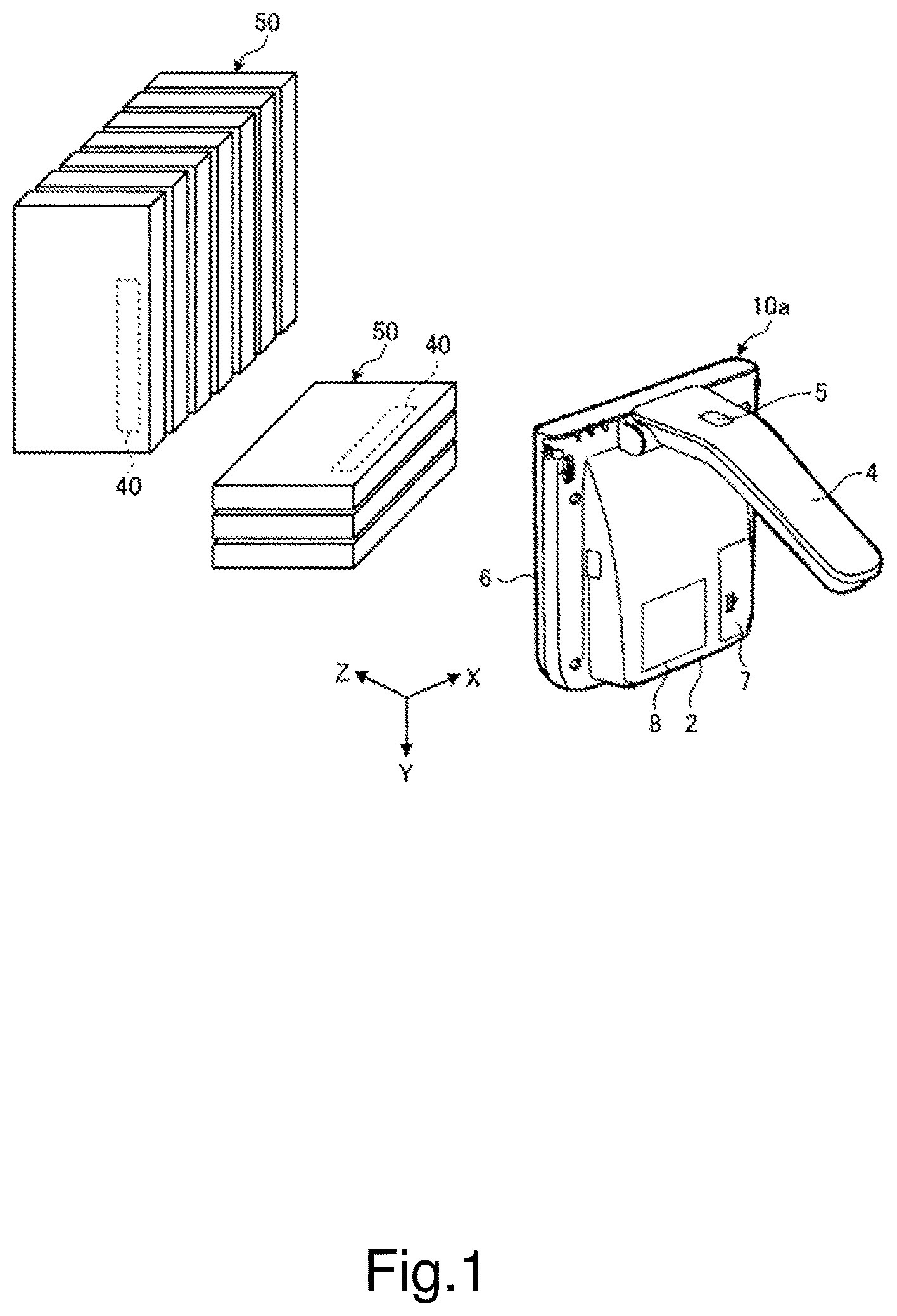
Referring to , an overall configuration of the wireless tag reading apparatus will be described. is an outer appearance perspective view showing an example of the wireless tag reading apparatus according to the first embodiment. The wireless tag reading apparatus 10 a is an RFID reader, for example.
The wireless tag reading apparatus 10 a includes a main body portion 2 , a grip portion 4 , a trigger switch 5 , and a liquid-crystal display 8 . The liquid-crystal display 8 includes an operation unit such as a touch panel, for example. The main body portion 2 includes an RFID antenna 6 and a battery 7 . The main body portion 2 performs wireless communication with radio frequency identification (RFID) tags 40 that are examples of wireless tags attached to articles. The RFID antenna 6 transmits and receives a radio wave for performing wireless communication with the RFID tags 40 . It should be noted that the wireless communication with the RFID tags 40 will be described later in detail.
The grip portion 4 is a portion that an operator grips during operation. The grip portion 4 is disposed on a rear side of the main body portion 2 . The grip portion 4 is provided with the trigger switch 5 . When the operator turns on the trigger switch 5 while gripping the grip portion 4 , the wireless tag reading apparatus 10 a emits a radio wave from the RFID antenna 6 . Then, when the operator turns off the trigger switch 5 , the wireless tag reading apparatus 10 a stops emission of a radio wave from the RFID antenna 6 . The liquid-crystal display 8 displays an operation state of the wireless tag reading apparatus 10 a , tag information of the RFID tag 40 read by the wireless tag reading apparatus 10 a , and the like. It should be noted that the tag information is information stored in the RFID tag 40 as will be described later.
The RFID tag 40 receives a radio wave emitted from the RFID antenna 6 and transmits, as the response, an electronic product code (EPC) that is an identifier that uniquely identifies an article 50 attached to the RFID tag 40 to the wireless tag reading apparatus 10 a . The wireless tag reading apparatus 10 a completes reading of the RFID tag 40 b by receiving the EPC. It should be noted that the EPC is an example of the tag information in this embodiment.
It is assumed that the article 50 is placed in a horizontal direction along the X-axis shown in or in a vertical direction along the Y-axis. Then, it is assumed that the RFID tag 40 attached to the article 50 also exists along the X-axis or the Y-axis.
When a plurality of RFID tags 40 reply to a radio wave emitted from the RFID antenna 6 at the same time, the wireless tag reading apparatus 10 a cannot identify and read information of each RFID tag 40 . Therefore, the wireless tag reading apparatus 10 a includes a collision preventing algorithm (anti-collision) for reading the responses from the respective RFID tags 40 in sequence. It will be described later in detail.
When the wireless tag reading apparatus 10 a is activated, the RFID tags 40 attached to the articles 50 within a range within which a radio wave emitted from the RFID antenna 6 can reach the RFID tags 40 enter a stand-by state by being fed with electric power from the emitted radio wave. The RFID tags 40 each include an inventory check flag. The inventory check flag is a flag indicating whether or not its information has been read (detected). Under the stand-by state, the inventory check flag of the RFID tag 40 is in an “undetected” state that is its initial value.
Next, the wireless tag reading apparatus 10 a issues a select command in which the article type of a search target has been specified as a parameter. Accordingly, an RFID tag 40 of the RFID tags 40 that have entered the stand-by state, which is of the article type specified as the parameter, is activated. Next, the wireless tag reading apparatus 10 a issues a query command. When the RFID tag 40 receives the query command, the RFID tag 40 shifts to a response state from the stand-by state and generates and transmits a random number message (RN16) for identifying the RFID tag 40 itself. When the wireless tag reading apparatus 10 a receives the random number message, the wireless tag reading apparatus 10 a transmits an acknowledgement (ACK) command including its random number message. When the RFID tag 40 receives the ACK command, the RFID tag 40 shifts to an approval state from the response state. Under this approval state, the RFID tag 40 transmits the above-mentioned EPC that is the unique identifier and sets the inventory check flag to be in a “detected” state.
The wireless tag reading apparatus 10 a reads the EPC included in the received response wave. Then, since the RFID tag 40 that has transmitted the EPC sets the inventory check flag to be in the “detected” state, the RFID tag 40 does not react even if the wireless tag reading apparatus 10 a issues the query command again. Since the RFID tag 40 in the detected state does not react, the wireless tag reading apparatus 10 a does not read the RFID tag 40 in the detected state twice. Therefore, if there is a plurality of RFID tags 40 , the wireless tag reading apparatus 10 a is capable of identifying and reading each RFID tag 40 .
(Description of Structure of RFID Antenna)
Next, configurations of the RFID antenna 6 and power feeding ports 15 a , 15 b will be described with reference to . is a diagram showing an example of the configuration of the RFID antenna.
The RFID antenna 6 is capable of emitting a first linearly polarized wave having a first plane of polarization and a second linearly polarized wave having a second plane of polarization different in direction from the first plane of polarization and receiving a response wave from the RFID tag 40 . Specifically, the RFID antenna 6 has a structure in which an antenna element 12 is housed inside a rectangular casing 11 . The antenna element 12 is a substrate antenna formed on a substrate, for example, and includes a first antenna element 12 a along the X-axis and a second antenna element 12 b along the Y-axis, the first antenna element 12 a and the second antenna element 12 b extending in directions different from each other by 90° while sharing a single vertex.
The first antenna element 12 a has the rectangular shape along the X-axis and the second antenna element 12 b has the rectangular shape along the Y-axis. Bottom surfaces of the first antenna element 12 a and the second antenna element 12 b are covered with a bottom surface conductor 13 . Moreover, outer side surfaces of the first antenna element 12 a and the second antenna element 12 b are covered with a side surface conductor 14 . The bottom surface conductor 13 and the side surface conductor 14 are conductors formed from metal and the like.
A power feeding port 15 a feeds electric power into the RFID antenna so as to emit the first linearly polarized wave from the RFID antenna 6 . Specifically, the first antenna element 12 a is fed with a high-frequency signal from the power feeding port 15 a via a signal line. It should be noted that the signal line is a coaxial cable covered with an insulator and an outer conductor. The outer conductor shields the signal line in such a manner that the input side and the output side are both connected to the GND. With this configuration, high-frequency signal current flows in the first antenna element 12 a in an X-axis direction. Then, the first antenna element 12 a emits a linearly polarized wave in the Z-axis direction, the linearly polarized wave having an XZ-plane as the plane of polarization. It should be noted that the power feeding port 15 a is an example of a first power feeding unit in this embodiment. Moreover, the linearly polarized wave having the XZ-plane as the plane of polarization is an example of the first linearly polarized wave having the first plane of polarization in this embodiment.
Moreover, the power feeding port 15 a feeds electric power into the RFID antenna so as to emit the first linearly polarized wave from the RFID antenna 6 . Specifically, the second antenna element 12 b is fed with a high-frequency signal from a power feeding port 15 b via a signal line. The signal line is a coaxial cable as described above. With this configuration, high-frequency signal current flows in the second antenna element 12 b in a Y-axis direction. Then, the second antenna element 12 b emits a linearly polarized wave having a YZ-plane as the plane of polarization in a Z-axis direction. It should be noted that the power feeding port 15 b is an example of a second power feeding unit in this embodiment. Moreover, the linearly polarized wave having the YZ-plane as the plane of polarization is an example of the second linearly polarized wave having the second plane of polarization in this embodiment.
In this manner, the linear antennas are arranged to be orthogonal to each other at the same position and only one of the antennas is fed with electric power, such that the linearly polarized wave having the plane of polarization according to the direction of the antenna can be emitted. Therefore, the linearly polarized wave having the plane of polarizations different from each other by 90° can be switched and emitted by feeding electric power into one antenna and the other antenna in a time division manner.
(Hardware Configuration of RFID Tag)
Next, a hardware configuration of the RFID tag 40 will be described with reference to . is a block diagram showing an example of the hardware configuration of the RFID tag.
The RFID tag 40 includes an antenna 41 , a transmitting/receiving device 42 , a controller 43 , an electromotive device 44 , and a memory 45 . The antenna 41 receives a radio wave emitted from the RFID antenna 6 of the wireless tag reading apparatus 10 a . The transmitting/receiving device 42 transmits and receives a radio wave through the antenna 41 . The controller 43 controls a general operation associated with reading of the RFID tag 40 . The electromotive device 44 generates electric power for activating the RFID tag 40 on the basis of a radio wave that the antenna 41 has received from the wireless tag reading apparatus 10 a . Moreover, the electromotive device 44 generates electric power for performing control to transmit the EPC (tag information) stored in the RFID tag 40 to the wireless tag reading apparatus 10 a , for example. The memory stores the EPC (tag information) such as article information of the article with the RFID tag 40 attached thereto.
(Description of Hardware Configuration of Wireless Tag Reading Apparatus)
Next, a hardware configuration of the wireless tag reading apparatus 10 a will be described with reference to . is a hardware block diagram showing an example of the hardware configuration of the wireless tag reading apparatus according to the first embodiment.
The wireless tag reading apparatus 10 a performs wireless communication with the RFID tags 40 attached to the articles and reads information associated with the articles stored in the RFID tag 40 for performing stock management, sales management, and the like of the articles. The wireless tag reading apparatus 10 a includes a controller 20 , a storage device 21 , an input/output controller 23 , and the battery 7 .
The controller 20 connects the storage device 21 and the input/output controller 23 via an internal bus 22 . The battery 7 supplies electric power into the respective portions of the wireless tag reading apparatus 10 a.
The controller 20 includes a central processing unit (CPU) 20 a , a read only memory (ROM) 20 b , a random access memory (RAM) 20 c . The CPU 20 a connects to the ROM 20 b and the RAM 20 c via the internal bus 22 . The CPU 20 a expands various types of programs and files stored in the ROM 20 b and/or the storage device 21 , in the RAM 20 c . The CPU 20 a operates in accordance with the various types of programs and files expanded in the RAM 20 c to thereby control the wireless tag reading apparatus 10 a . That is, the controller 20 has a configuration of a generally-used computer.
The controller 20 further connects to the storage device 21 , the input/output controller 23 , and the battery 7 via the internal bus 22 .
The storage device 21 is a nonvolatile memory such as a flash memory in which stored information is retained also when powered off, a hard disk drive (HDD), or the like. The storage device 21 stores programs and the like including a control program P 1 . The control program P 1 is a program for executing the functions of the wireless tag reading apparatus 10 a.
It should be noted that the control program P 1 may be provided, stored in the ROM 20 b in advance. Moreover, the control program P 1 may be provided, recorded in a recording medium readable by a computer, such as a CD-ROM, a flexible disk (FD), a CD-R, and a digital versatile disc (DVD) in a file in an installable format or an executable format in the controller 20 . In addition, the control program P 1 may be stored in a computer connected to a network such as the Internet and may be provided by downloading it via the network. Moreover, the control program P 1 may be provided or delivered via a network such as the Internet.
Moreover, the storage device 21 stores a read data D. The read data D is the EPC (tag information) or the like read by the wireless tag reading apparatus 10 a from the RFID tag 40 .
Referring back to , the input/output controller 23 connects the controller 20 to the first antenna element 12 a , the second antenna element 12 b , the trigger switch 5 , and the liquid-crystal display 8 . The input/output controller 23 controls various types of hardware connected on the basis of a command from the controller 20 . In other words, the controller 20 controls various types of hardware connected via the input/output controller 23 .
It should be noted that the functions of the first antenna element 12 a , the second antenna element 12 b , the trigger switch 5 , and the liquid-crystal display 8 are as described above.
The battery 7 is a secondary battery such as a lithium-ion battery that supplies electric power into the wireless tag reading apparatus 10 a and peripheral equipment connected to the wireless tag reading apparatus 10 a.
(Description of Functional Configuration of Wireless Tag Reading Apparatus)
Next, a functional configuration of the wireless tag reading apparatus 10 a will be described with reference to . is a block diagram showing an example of the functional configuration of the wireless tag reading apparatus according to the first embodiment.
By expanding the control program P 1 in the RAM 20 c and executing it, the controller 20 of the wireless tag reading apparatus 10 a operates as a functional unit including a horizontally polarized wave power feeding unit 30 , a vertically polarized wave power feeding unit 31 , a plane-of-polarization switching unit 32 , a power feeding time ratio setting unit 33 , a wireless tag information reading unit 34 a , and a display control unit 35 as shown in .
The horizontally polarized wave power feeding unit 30 emits from the first antenna element 12 a a horizontally polarized wave (first linearly polarized wave) having a horizontal plane of polarization (first plane of polarization). It should be noted that the horizontally polarized wave power feeding unit 30 is an example of the first power feeding unit in this embodiment together with the above-mentioned power feeding port 15 a.
The vertically polarized wave power feeding unit 31 emits from the second antenna element 12 b a vertically polarized wave (second linearly polarized wave) having a perpendicular plane of polarization (second plane of polarization). It should be noted that the vertically polarized wave power feeding unit 31 is an example of the second power feeding unit in this embodiment together with the above-mentioned power feeding port 15 b.
The plane-of-polarization switching unit 32 switches between power feeding into the first antenna element 12 a from the power feeding port 15 a under the control of the horizontally polarized wave power feeding unit 30 and power feeding into the second antenna element 12 b from the power feeding port 15 b under the control of the vertically polarized wave power feeding unit 31 . In other words, the plane-of-polarization switching unit 32 switches between emission from the first antenna element 12 a and emission from the second antenna element 12 b.
The power feeding time ratio setting unit 33 sets a ratio of a time of power feeding into the first antenna element 12 a from the power feeding port 15 a under the control of the horizontally polarized wave power feeding unit 30 to a time of power feeding into the second antenna element 12 b from the power feeding port 15 b under the control of the vertically polarized wave power feeding unit 31 to take a value according to a ratio of the number of RFID tags 40 (wireless tags) existing in a direction of the horizontally polarized wave and the number of RFID tags 40 (wireless tags) existing in a direction of the vertically polarized wave. It should be noted that the power feeding time ratio setting unit 33 is an example of a setting unit in this embodiment.
The wireless tag information reading unit 34 a receives via the RFID antenna 6 a response wave of a radio wave emitted by the RFID antenna 6 to thereby read the EPC (tag information) of the RFID tag 40 . Specifically, the wireless tag information reading unit 34 a sets a maximum bit length of a random number stored in a slot counter included in each RFID tag 40 in accordance with the number of tags N 1 of the RFID tags 40 read by a response wave of a horizontally polarized wave and the number of tags N 2 of the RFID tags 40 read by a response wave of a vertically polarized wave. The wireless tag information reading unit 34 a sets the maximum bit length to thereby efficiently read all the EPCs (tag information) of the RFID tags 40 . It will be described later in detail (see ). It should be noted that the wireless tag information reading unit 34 a is an example of a reading unit in this embodiment.
The display control unit 35 causes the liquid-crystal display 8 to display the EPCs and the like of the RFID tags 40 read by the wireless tag information reading unit 34 a.
(Description of Plane-of-Polarization Switching Processing)
The plane-of-polarization switching unit 32 switches between power feeding into the first antenna element 12 a from the power feeding port 15 a under the control of the horizontally polarized wave power feeding unit 30 and power feeding into the second antenna element 12 b from the power feeding port 15 b under the control of the vertically polarized wave power feeding unit 31 . Accordingly, the plane-of-polarization switching unit 32 switches between emission of the horizontally polarized wave (first linearly polarized wave) from the first antenna element 12 a and emission of the vertically polarized wave (second linearly polarized wave) from the second antenna element 12 b.
Then, the wireless tag information reading unit 34 a reads the EPCs of the RFID tags 40 existing in the horizontal direction (along the X-axis of ) by a response wave of the horizontally polarized wave emitted from the first antenna element 12 a . Moreover, the wireless tag information reading unit 34 a reads the EPCs of the RFID tags 40 existing in the vertical direction (along the Y-axis of ) by a response wave of the vertically polarized wave emitted from the second antenna element 12 b.
It should be noted that if the article 50 is placed in a direction deviated from the X-axis or the Y-axis, the EPC of the RFID tag 40 attached to the article 50 is read by both of the horizontally polarized wave and the vertically polarized wave or is not read by both of the horizontally polarized wave and the vertically polarized wave.
The plane-of-polarization switching unit 32 switches between emission of the horizontally polarized wave and emission of the vertically polarized wave at the time ratio set by the power feeding time ratio setting unit 33 . In a case where a ratio (N 1 /N 2 ) of the number of tags N 1 of the articles 50 placed in the horizontal direction to the number of tags N 2 of the articles 50 placed in the vertical direction is known in advance under a reading environment of the RFID tags 40 , the operator of the wireless tag reading apparatus 10 a gives a value according to this ratio to the power feeding time ratio setting unit 33 . For example, in a case where the ratio (N 1 /N 2 ) is 2, the operator gives an instruction to the power feeding time ratio setting unit 33 via the operation unit of the liquid-crystal display 8 such that the time to emit the horizontally polarized wave is about twice as long as the time to emit the vertically polarized wave, to thereby cause the power feeding time ratio setting unit 33 to set that ratio.
It should be noted that in a case where the ratio (N 1 /N 2 ) is unknown because so many articles 50 are placed, the operator gives an instruction to the power feeding time ratio setting unit 33 such that the ratio of the time to emit the horizontally polarized wave to the time to emit the vertically polarized wave is a one to one ratio, to thereby cause the wireless tag reading apparatus 10 a to perform preliminary reading of the RFID tags 40 . Then, the power feeding time ratio setting unit 33 sets the ratio of the time to emit the horizontally polarized wave to the time to emit the vertically polarized wave on the basis of the number of tags of the RFID tags 40 read by the horizontally polarized wave and the number of tags of the RFID tags 40 read by the vertically polarized wave, to thereby cause the wireless tag information reading unit 34 a to perform main reading.
(Description of Method of Reading Tag Information)
Next, a flow of processing of reading the RFID tags 40 , which is performed by the controller 20 (wireless tag information reading unit 34 a ) of the wireless tag reading apparatus 10 a , will be described with reference to . is a time chart showing an example of the flow of processing performed by the wireless tag reading apparatus according to the first embodiment. The horizontal axis in indicates a time t.
When the wireless tag reading apparatus 10 a emits (transmits) a carrier wave CW (radio wave), the RFID tags 40 that have received this carrier wave are activated. Subsequently, the wireless tag reading apparatus 10 a transmits a query command. The query command includes data for informing of a maximum value of the random number to be generated by each RFID tag 40 for avoiding the collision of the RFID tags 40 . More specifically, that data is data regarding the maximum bit length of the slot counter that stores the random number generated by each RFID tag 40 . When the RFID tag 40 receives the query command, the RFID tag 40 generates a random number equal to or smaller than the maximum value included in the query command and stores the the generated random number in its slot counter. In the example of , for the sake of description, it is assumed that the maximum value of the random number to be generated is “4” (the maximum bit length of the slot counter is 2). That is, the counter value that is set by each RFID tag 40 is 0, 1, 2, or 3.
In the example shown in , it is assumed that an RFID tag 40 a generates a random number 0, an RFID tag 40 b generates a random number 3, and an RFID tag 40 c generates a random number 2. The random numbers generated in this manner are stored in the slot counters of the RFID tags, respectively.
The RFID tag 40 a immediately transmits a response of RN16 because the counter value is 0. RN16 is a random number message having a maximum bit length of 16. When the wireless tag reading apparatus 10 a receives RN16, the wireless tag reading apparatus 10 a transmits an ACK command. When the RFID tag 40 a receives the ACK command, the RFID tag 40 a transmits PC+EPC+CRC 16 including the identification information. PC (protocol control) is information including information regarding a word length of the EPC, the presence/absence of a user memory, an extended indicator, and the like. The EPC is, as described above, the tag information for uniquely identifying the article 50 with the RFID tag 40 attached thereto. The CRC (cyclic redundancy check) 16 is a kind of error detection symbol.
The wireless tag reading apparatus 10 a transmits a QueryRep command and decrements the counter value of the RFID tag 40 a after receiving the signal including the identification information. When the RFID tag 40 a receives the QueryRep command, the RFID tag 40 a determines that the transmitted identification information is correctly transmitted.
When the RFID tag 40 b and the RFID tag 40 c receive the QueryRep command, the RFID tag 40 b and the RFID tag 40 c each decrement the counter value of the slot counter. As a result of decrement, the counter value of the RFID tag 40 b is “2” and the counter value of the RFID tag 40 c is “1”, and thus there are no tags that transmit responses. In a case where the wireless tag reading apparatus 10 a determines that no responses are transmitted even after a certain time elapses after transmitting the QueryRep command, the wireless tag reading apparatus 10 a transmits a next QueryRep command. The RFID tags 40 b and 40 c each transmit a response when the counter value becomes 0.
When the wireless tag reading apparatus 10 a performs transmitting a number of times corresponding to the maximum bit length designated by the query command (four in the example of ), the wireless tag reading apparatus 10 a stops transmission of the carrier wave.
Even in a case where the plurality of RFID tags 40 exist as described above, the wireless tag reading apparatus 10 a makes it unlikely that the responses of the RFID tags 40 will collide with each other.
(Description of Flow of Processing Performed by Wireless Tag Reading Apparatus)
Next, processing performed by the wireless tag reading apparatus 10 a will be described with reference to . is a flowchart showing an example of the processing performed by the controller 20 of the wireless tag reading apparatus 10 a according to the first embodiment.
In Step S 10 , the power feeding time ratio setting unit 33 of the controller 20 obtains the number of tags N 1 of the articles 50 placed in the horizontal direction and the number of tags N 2 of the articles 50 placed in the vertical direction. Specifically, the operator of the wireless tag reading apparatus 10 a may designate a rough number of tags checked by eyes via the operation unit of the liquid-crystal display 8 , for example. Alternatively, in a case where a theoretical stock quantity of the articles 50 is known like inventory check work, a value of the half of the stock quantity may be designated as each of the number of tags N 1 and the number of tags N 2 .
In Step S 11 , the power feeding time ratio setting unit 33 of the controller 20 determines whether or not the number of tags N 1 and the number of tags N 2 are equal. In a case where it is determined that the number of tags N 1 and the number of tags N 2 are equal (Yes in Step S 11 ), the processing of the controller 20 proceeds to Step S 12 . On the other hand, in a case where it is determined that the number of tags N 1 and the number of tags N 2 are not equal (No in Step S 11 ), the processing of the controller 20 proceeds to Step S 13 .
In Step S 12 , the wireless tag information reading unit 34 a of the controller 20 sets a maximum bit length L 1 of the slot counter of the RFID tag 40 read when emitting the horizontally polarized wave and a maximum bit length L 2 of the slot counter of the RFID tag 40 read when emitting the vertically polarized wave such that the relation L 1 =L 2 is established. Then, the processing of the controller 20 proceeds to Step S 16 .
On the other hand, in Step S 13 , the power feeding time ratio setting unit 33 of the controller 20 determines whether or not the number of tags N 1 is equal to or larger than the number of tags N 2 . In a case where it is determined that the number of tags N 1 is equal to or larger than the number of tags N 2 (Yes in Step S 13 ), the processing of the controller 20 proceeds to Step S 14 . On the other hand, it is determined that the number of tags N 1 is not equal to or larger than the number of tags N 2 (No in Step S 13 ), the processing of the controller 20 proceeds to Step S 15 .
In Step S 14 , the wireless tag information reading unit 34 a of the controller 20 sets the maximum bit length L 1 of the slot counter of the RFID tag 40 read when emitting the horizontally polarized wave and the maximum bit length L 2 of the slot counter of the RFID tag 40 read when emitting the vertically polarized wave such that the relation L 1 >L 2 is established. Then, the processing of the controller 20 proceeds to Step S 16 .
On the other hand, in Step S 15 , the wireless tag information reading unit 34 a of the controller 20 sets the maximum bit lengths L 1 and L 2 of the slot counters such that the relation L 1 <L 2 is established. Then, the processing of the controller 20 proceeds to Step S 16 .
In Step S 16 following the processing of Step S 12 , Step S 14 , or Step S 15 , the plane-of-polarization switching unit 32 of the controller 20 switches the power feeding control unit to the horizontally polarized wave power feeding unit 30 (first power feeding unit).
In Step S 17 , the horizontally polarized wave power feeding unit 30 of the controller 20 starts emission of the horizontally polarized wave (first linearly polarized wave) from the first antenna element 12 a.
In Step S 18 , the wireless tag information reading unit 34 a of the controller 20 causes each RFID tag 40 that has received the horizontally polarized wave to generate a random number of the maximum bit length L 1 in accordance with the query command transmitted superimposed on the horizontally polarized wave.
In Step S 18 , the wireless tag information reading unit 34 a of the controller 20 reads the tag information from each RFID tag 40 .
In Step S 20 , the wireless tag information reading unit 34 a of the controller 20 counts the number of read tags.
In Step S 21 , the wireless tag information reading unit 34 a of the controller 20 determines whether or not reading of the tag information of the RFID tag 40 has been completed. In a case where it is determined that reading of the tag information of the RFID tag 40 has been completed (Yes in Step S 21 ), the processing of the controller 20 proceeds to Step S 22 . On the other hand, in a case where it is determined that reading of the tag information of the RFID tag 40 has not been completed (No in Step S 21 ), the processing of the controller 20 returns to Step S 19 .
It should be noted that in Step S 21 , the determination of the controller 20 as to whether or not reading of the tag information of the RFID tag 40 has been completed is performed by determining whether or not the wireless tag reading apparatus 10 a has performed transmission a number of times corresponding to the maximum bit length designated by the query command.
In Step S 22 , the horizontally polarized wave power feeding unit 30 of the controller 20 stops emission of the horizontally polarized wave (first linearly polarized wave) from the first antenna element 12 a.
Next, in Step S 23 , the plane-of-polarization switching unit 32 of the controller 20 switches the power feeding control unit to the vertically polarized wave power feeding unit 31 (second power feeding unit).
In Step S 24 , the vertically polarized wave power feeding unit 31 of the controller 20 starts emission of the vertically polarized wave (second linearly polarized wave) from the second antenna element 12 b.
In Step S 25 , the wireless tag information reading unit 34 a of the controller 20 causes each RFID tag 40 that has received the vertically polarized wave to generate a random number of the maximum bit length L 2 in accordance with the query command transmitted superimposed on the vertically polarized wave.
In Step S 26 , the wireless tag information reading unit 34 a of the controller 20 reads the tag information from each RFID tag 40 .
In Step S 27 , the wireless tag information reading unit 34 a of the controller 20 counts the number of read tags.
In Step S 28 , the wireless tag information reading unit 34 a of the controller 20 determines whether or not reading of the tag information of the RFID tag 40 has been completed. In a case where it is determined that reading of the tag information of the RFID tag 40 has been completed (Yes in Step S 28 ), the processing of the controller 20 proceeds to Step S 29 . On the other hand, in a case where it is determined that reading of the tag information of the RFID tag 40 has not been completed (No in Step S 28 ), the processing of the controller 20 returns to Step S 26 .
It should be noted that in Step S 28 , the determination as to whether or not reading of the tag information of the RFID tag 40 has been completed is performed by determining whether or not the wireless tag reading apparatus 10 a has performed transmission a number of times corresponding to the maximum bit length designated by the query command.
In Step S 29 , the vertically polarized wave power feeding unit 31 of the controller 20 stops emission of the vertically polarized wave (second linearly polarized wave) from the second antenna element 12 b.
In Step S 30 following Step S 29 , the wireless tag information reading unit 34 a of the controller 20 determines whether or not reading of all the RFID tags 40 has been completed. In a case where it is determined that reading of all the RFID tags 40 has been completed (Yes in Step S 30 ), the controller 20 of the wireless tag reading apparatus 10 a terminates the processing of . On the other hand, in a case where it is determined that reading of all the RFID tags 40 has not been completed (No in Step S 30 ), the processing of the controller 20 returns to Step S 10 .
It should be noted that in Step S 30 , the determination as to whether or not all the RFID tags 40 have been read may be performed by a method depending on situations where the wireless tag reading apparatus 10 a is used. For example, in a case where the wireless tag reading apparatus 10 a is performing stock taking of the articles 50 , it is sufficient to determine whether or not all the RFID tags 40 have been read by checking the contents of the read tag information against management information of the stock taking. Moreover, in a case where the wireless tag reading apparatus 10 a is performing reading of commodity information of the articles to be purchased by a customer, it is sufficient to determine whether or not all the RFID tags 40 have been read by checking the number of read articles 50 against the number of articles 50 that the operator of the wireless tag reading apparatus 10 a has checked by eyes.
As described above, in accordance with the wireless tag reading apparatus 10 a according to the first embodiment, the power feeding time ratio setting unit 33 (setting unit) sets the ratio of the time to feed electric power into the first antenna element 12 a from the power feeding port 15 a under the control of the horizontally polarized wave power feeding unit (first power feeding unit) to the time to feed electric power into the second antenna element 12 b from the power feeding port 15 b under the control of the vertically polarized wave power feeding unit 31 (second power feeding unit) to take the value according to the ratio of the number of wireless tags existing in the direction of the first linearly polarized wave to the number of wireless tags existing in the direction of the second linearly polarized wave. Then, the plane-of-polarization switching unit 32 switches between power feeding into the first antenna element 12 a from the power feeding port 15 a under the control of the horizontally polarized wave power feeding unit 30 (first power feeding unit) and power feeding into the second antenna element 12 b from the power feeding port 15 b under the control of the vertically polarized wave power feeding unit 31 (second power feeding unit) at the ratio of the power feeding time set by the power feeding time ratio setting unit 33 . Then, the wireless tag information reading unit 34 a (reading unit) receives a response wave of the first linearly polarized wave or the second linearly polarized wave to thereby read the tag information of the RFID tag 40 (wireless tag) included in the response wave. Therefore, all the EPCs (tag information) of the RFID tags 40 can be efficiently read while securing the communication distance with the plurality of RFID tags 40 the direction of arrangement of which is unknown.
Moreover, in the wireless tag reading apparatus 10 a according to the first embodiment, the value according to the ratio of the number of RFID tags 40 existing in the direction of the first linearly polarized wave and the number of RFID tags 40 existing in the direction of the second linearly polarized wave is the ratio of the number of RFID tags 40 read by the horizontally polarized wave (first linearly polarized wave) to the number of RFID tags 40 read by the vertically polarized wave (second linearly polarized wave). Therefore, the time required for reading all the RFID tags 40 can be shortened by changing the time to emit a radio wave for example, in accordance with the number of tags of the RFID tags 40 of the articles 50 placed in a direction along the linearly polarized wave emitted by the wireless tag reading apparatus 10 a . Moreover, in a case where the number of tags of the RFID tags 40 is unknown and the horizontally polarized wave and the vertically polarized wave have been emitted for the same time for example, the ratio of the time to emit the horizontally polarized wave to the time to emit the vertically polarized wave can also be changed on the basis of the number of tags of the RFID tags 40 read by the horizontally polarized wave and the number of tags of the RFID tags 40 read by the vertically polarized wave when performing reading again.
Moreover, in the wireless tag reading apparatus 10 a according to the first embodiment, the power feeding time ratio setting unit 33 (setting unit) sets the maximum bit length of the slot counter set in the RFID tag 40 when emitting the horizontally polarized wave and the maximum bit length of the slot counter set in the RFID tag 40 when emitting the vertically polarized wave in accordance with the ratio of the number of RFID tags 40 read by the horizontally polarized wave (first linearly polarized wave) to the number of RFID tags 40 read by the vertically polarized wave (second linearly polarized wave). Therefore, when emitting radio wave of the horizontally polarized wave and the vertically polarized wave, which are envisaged to be capable of reading a larger number of RFID tags 40 , all the RFID tags 40 can be reliably read while saving the total reading time by reliably performing reading of the RFID tag 40 by those radio waves.
Moreover, in the wireless tag reading apparatus 10 a according to the first embodiment, the power feeding time ratio setting unit 33 (setting unit) sets, in a case where the number of RFID tags 40 read by the horizontally polarized wave (first linearly polarized wave) is larger than the number of RFID tags 40 read by the vertically polarized wave (second linearly polarized wave), the maximum bit length of the slot counter set in the RFID tag 40 when emitting the horizontally polarized wave to be longer than the maximum bit length of the slot counter set in the RFID tag 40 when emitting the vertically polarized wave. Therefore, in a case where a larger number of RFID tags 40 exist in the horizontal direction than in the vertical direction, the time to emit the horizontally polarized wave is set to be longer than the time to emit the vertically polarized wave. On the contrary, in a case where a larger number of RFID tags 40 exist in the vertical direction than in the horizontal direction, the maximum bit length of the slot counter set in the RFID tag 40 when emitting the vertically polarized wave is set to be longer than the maximum bit length of the slot counter set in the RFID tag 40 when emitting the horizontally polarized wave. Therefore, the time to emit the vertically polarized wave is set to be longer than the time to emit the horizontally polarized wave. With this configuration, all the EPCs (tag information) of the RFID tags 40 can be efficiently read irrespective of the direction of placement of the RFID tags 40 .
Second Embodiment
Hereinafter, a wireless tag reading apparatus 10 b and a control method for the wireless tag reading apparatus 10 b according to a second embodiment will be described. It should be noted that the hardware configuration of the wireless tag reading apparatus 10 b is the same as the hardware configuration (see ) of the wireless tag reading apparatus 10 a , and thus a description thereof will be omitted.
(Description of Overall Configuration of Wireless Tag Reading Apparatus)
is a block diagram showing an example of a functional configuration of the wireless tag reading apparatus 10 b according to the second embodiment. The controller 20 of the wireless tag reading apparatus 10 b includes a wireless tag information reading unit 34 b instead of the wireless tag information reading unit 34 a of the controller 20 of the wireless tag reading apparatus 10 a.
The wireless tag information reading unit 34 b reads the EPC (tag information) of the RFID tag 40 by receiving the response wave to the radio wave emitted by the RFID antenna 6 . Specifically, the wireless tag information reading unit 34 b repeats the processing from the start of radio wave transmission and the stop of radio wave transmission a number of times corresponding to the number of tags of the RFID tags 40 . With this configuration, the wireless tag information reading unit 34 b efficiently reads all the EPCs (tag information) of the RFID tags 40 . It will be described later in detail. It should be noted that the wireless tag information reading unit 34 b is an example of the reading unit in this embodiment.
(Description of Method of Reading Tag Information)
Next, processing of reading the RFID tags 40 , which is performed by the wireless tag information reading unit 34 b of the wireless tag reading apparatus 10 b , will be described. Irrespective of emission of the horizontally polarized wave and emission of the vertically polarized wave, the wireless tag information reading unit 34 b individually sets the number of times to repeat the processing (inventory round) from the start of radio wave transmission to the stop of radio wave transmission described in when emitting the horizontally polarized wave and when emitting the vertically polarized wave without changing the maximum bit length of the slot counter set in each RFID tag 40 .
That is, when emitting a polarized wave closer to a direction in which the number of tags of the RFID tags 40 is larger, the number of times to repeat the processing shown in is set to be larger. With this configuration, the RFID tags 40 not read in first reading processing can be reliably read in second, third, . . . reading processing. It should be noted that at this time, it is desirable that the operator of the wireless tag reading apparatus 10 b perform reading by moving the RFID antenna 6 of the wireless tag reading apparatus 10 b closer to the article 50 or changing the direction of the RFID antenna 6 of the wireless tag reading apparatus 10 b for changing the positional relationship between the RFID tag 40 and the RFID antenna 6 .
(Description of Flow of Processing Performed by Wireless Tag Reading Apparatus)
Next, processing performed by the wireless tag reading apparatus 10 b will be described with reference to . is a flowchart showing an example of the processing performed by the wireless tag reading apparatus 10 b according to the second embodiment.
In Step S 40 , the power feeding time ratio setting unit 33 of the controller 20 obtains the number of tags N 1 of the articles 50 placed in the horizontal direction and the number of tags N 2 of the articles 50 placed in the vertical direction.
In Step S 41 , the power feeding time ratio setting unit 33 of the controller 20 determines whether or not the number of tags N 1 and the number of tags N 2 are equal. In a case where it is determined that the number of tags N 1 and the number of tags N 2 are equal (Yes in Step S 41 ), the processing of the controller 20 proceeds to Step S 42 . On the other hand, in a case where it is determined that the number of tags N 1 and the number of tags N 2 are equal (No in Step S 41 ), the processing of the controller 20 proceeds to Step S 43 .
In Step S 42 , the wireless tag information reading unit 34 b of the controller 20 sets the number of times R 1 to repeat the inventory round when emitting the horizontally polarized wave and the number of times R 2 to repeat the inventory round when emitting the vertically polarized wave such that the relation R 1 =R 2 is established. Then, the processing of the controller 20 proceeds to Step S 46 .
On the other hand, in Step S 43 , the power feeding time ratio setting unit 33 of the controller 20 determines whether or not the number of tags N 1 is equal to or larger than the number of tags N 2 . In a case where it is determined that the number of tags N 1 is equal to or larger than the number of tags N 2 (Yes in Step S 43 ), the processing of the controller 20 proceeds to Step S 44 . On the other hand, it is determined that the number of tags N 1 is not equal to or larger than the number of tags N 2 (No in Step S 43 ), the processing of the controller 20 proceeds to Step S 45 .
In Step S 44 , the wireless tag information reading unit 34 b of the controller 20 sets the number of times R 1 to repeat the inventory round when emitting the horizontally polarized wave and the number of times R 2 to repeat the inventory round when emitting the vertically polarized wave such that the relation R 1 >R 2 is established. Then, the processing of the controller 20 proceeds to Step S 46 .
On the other hand, in Step S 45 , the wireless tag information reading unit 34 b of the controller 20 sets the number of times R 1 to repeat the inventory round and the number of times R 2 to repeat the inventory round such that the relation R 1 <R 2 is established (Step S 45 ). Then, the processing of the controller 20 proceeds to Step S 46 .
In Step S 46 following the processing of Step S 42 , Step S 44 , or Step S 45 , the plane-of-polarization switching unit 32 of the controller 20 switches the power feeding control unit to the horizontally polarized wave power feeding unit 30 (first power feeding unit).
In Step S 47 , the horizontally polarized wave power feeding unit 30 of the controller 20 starts emission of the horizontally polarized wave (first linearly polarized wave) from the first antenna element 12 a.
In Step S 48 , the wireless tag information reading unit 34 b of the controller 20 generates the random number of the maximum bit length L 1 in each RFID tag 40 that has received the horizontally polarized wave in accordance with the query command transmitted superimposed on the horizontally polarized wave.
In Step S 49 , the wireless tag information reading unit 34 b of the controller 20 reads the tag information from each RFID tag 40 .
In Step S 50 , the wireless tag information reading unit 34 b of the controller 20 determines whether or not reading of the tag information of the RFID tag 40 has been completed. In a case where it is determined that reading of the tag information of the RFID tag 40 has been completed (Yes in Step S 50 ), the processing of the controller 20 proceeds to Step S 51 . On the other hand, in a case where it is determined that reading of the tag information of the RFID tag 40 has not been completed (No in Step S 50 ), the processing of the controller 20 returns to Step S 49 .
In Step S 51 , the wireless tag information reading unit 34 b of the controller 20 determines whether or not the inventory round has been repeated the number of times R 1 to repeat. In a case where it is determined that the inventory round has been repeated the number of times R 1 to repeat (Yes in Step S 51 ), the processing of the controller 20 proceeds to Step S 52 . On the other hand, in a case where it is determined that the inventory round has been repeated the number of times R 1 to repeat (No in Step S 51 ), the processing of the controller 20 returns to Step S 48 . The controller 20 performs the processing of Steps S 48 to S 51 for a next inventory round.
In Step S 52 , the wireless tag information reading unit 34 b of the controller 20 counts the number of read tags.
Next, in Step S 53 , the horizontally polarized wave power feeding unit 30 of the controller 20 stops emission of the horizontally polarized wave (first linearly polarized wave) from the first antenna element 12 a.
Subsequently, in Step S 54 , the plane-of-polarization switching unit 32 of the controller 20 switches the power feeding control unit to the vertically polarized wave power feeding unit 31 (second power feeding unit).
In Step S 55 , the vertically polarized wave power feeding unit 31 of the controller 20 starts emission of the vertically polarized wave (second linearly polarized wave) from the second antenna element 12 b.
In Step S 56 , the wireless tag information reading unit 34 b of the controller 20 causes each RFID tag 40 that has received the vertically polarized wave to generate the random number of the maximum bit length L 1 in accordance with the query command transmitted superimposed on the vertically polarized wave.
In Step S 57 , the wireless tag information reading unit 34 b of the controller 20 reads the tag information from each RFID tag 40 .
In Step S 58 , the wireless tag information reading unit 34 b of the controller 20 determines whether or not reading of the tag information of the RFID tag 40 has been completed.
In a case where it is determined that reading of the tag information of the RFID tag 40 has been completed (Yes in Step S 58 ), the processing of the controller 20 proceeds to Step S 59 . On the other hand, in a case where it is determined that reading of the tag information of the RFID tag 40 has not been completed (No in Step S 58 ), the processing of the controller 20 returns to Step S 57 .
In Step S 59 , the wireless tag information reading unit 34 b of the controller 20 determines whether the inventory round has been repeated a number of times to repeat R 2 . In a case where it is determined that the inventory round has been repeated the number of times to repeat R 2 (Yes in Step S 59 ), the processing of the controller 20 proceeds to Step S 60 . On the other hand, in a case where it is determined that the inventory round has not been repeated the number of times to repeat R 2 (No in Step S 59 ), the processing of the controller 20 returns to Step S 56 . The controller 20 performs the the processing of Steps S 56 to S 58 for a next inventory round.
In Step S 60 , the wireless tag information reading unit 34 b of the controller 20 counts the number of read tags.
Next, in Step S 61 , the vertically polarized wave power feeding unit 31 of the controller 20 stops emission of the vertically polarized wave (second linearly polarized wave) from the second antenna element 12 b.
Next, in Step S 62 , the wireless tag information reading unit 34 b of the controller 20 determines whether or not reading of all the RFID tags 40 has been completed. In a case where it is determined that reading of all the RFID tags 40 has been completed (Yes in Step S 62 ), the wireless tag reading apparatus 10 b terminates the processing of . On the other hand, in a case where it is not determined that reading of all the RFID tags 40 has been completed (No in Step S 62 ), the processing of the controller 20 returns to Step S 40 .
As described above, in the wireless tag reading apparatus 10 b according to the second embodiment, the power feeding time ratio setting unit 33 (setting unit) sets the number of times to repeat the inventory round in accordance with the ratio of the number of read tags N 1 of the RFID tags by the use of the horizontally polarized wave (first linearly polarized wave) and the number of read tags N 2 of the RFID tags 40 by the use of the vertically polarized wave (second linearly polarized wave) when emitting the horizontally polarized wave and when emitting the vertically polarized wave. Therefore, the tag information of all the RFID tags 40 can be efficiently read while securing the communication distance with the plurality of RFID tags 40 the direction of arrangement of which is unknown.
Moreover, in the wireless tag reading apparatus 10 b according to the second embodiment, the power feeding time ratio setting unit 33 (setting unit) sets the number of times to repeat the inventory round when emitting the horizontally polarized wave to be larger than the number of times to repeat the inventory round when emitting the vertically polarized wave in a case where the number of read tags N 1 of the RFID tags 40 by the use of the horizontally polarized wave (first linearly polarized wave) is larger than the number of read tags N 2 of the RFID tags 40 by the use of the vertically polarized wave (second linearly polarized wave). Therefore, the time to emit the horizontally polarized wave is set to be longer than the time to emit the vertically polarized wave. On the contrary, in a case where a larger number of RFID tag 40 s exist in the vertical direction than the horizontal direction, the power feeding time ratio setting unit 33 (setting unit) sets the number of times to repeat the inventory round when emitting the vertically polarized wave to be larger than the number of times to repeat the inventory round when emitting the horizontally polarized wave. Therefore, the time to emit the vertically polarized wave is set to be longer than the time to emit the horizontally polarized wave. With this configuration, all the RFID tags 40 can be efficiently read irrespective of the direction of placement of the RFID tags 40 .
While certain embodiments have been described, these embodiments have been presented by way of example only, and are not intended to limit the scope of the inventions. Indeed, the novel embodiments described herein may be embodied in a variety of other forms; furthermore, various omissions, substitutions and changes in the form of the embodiments described herein may be made without departing from the spirit of the inventions. The accompanying claims and their equivalents are intended to cover such forms or modifications as would fall within the scope and spirit of the inventions.
Figures (9)
Citations
This patent cites (1)
- US20110193687