Cleaning Tool with Attachment, Attachment, and Cleaning Tool
Abstract
An attachment cleaning tool includes: a cleaning tool; and an attachment detachably attached to the cleaning tool. The cleaning tool includes: cleaning bodies that clean connection end surfaces of ferrules of an optical connector; head members each that press the cleaning bodies against the connection end surfaces; nozzle members that respectively accommodate the head members; a feeding mechanism that supplies and withdraws the cleaning bodies with respect to the head members; and an accommodating body which accommodates the feeding mechanism. Each of the connection members of the attachment includes: an attachment portion attached to a tip portion of each of the nozzle members; and a tubular portion that protrudes from the attachment portion in a longitudinal direction of the nozzle members and into which one of the ferrules is inserted. The connection members move following a relative movement of the nozzle members in the lateral direction.
Claims (7)
1. An attachment cleaning tool, comprising: a cleaning tool; an attachment detachably attached to the cleaning tool; a tip guide portion that protrudes toward the tubular portion and is formed at each tip portion of the nozzle members; an abutment portion on which the tip portion abuts and that is formed on an inner surface of the attachment portion; and an inner tubular portion formed at the abutment portion and that protrudes toward the nozzle member and enters an inside of the tip guide portion to be in contact with the tip guide portion, wherein the cleaning tool comprises: cleaning bodies that clean connection end surfaces of ferrules of an optical connector; head members each that press the cleaning bodies against the connection end surfaces; nozzle members that: respectively accommodate the head members, and move closer to each other or away from each other in a lateral direction in which the nozzle members are arranged; a feeding mechanism that supplies and withdraws the cleaning bodies with respect to the head members; and an accommodating body which accommodates the feeding mechanism, the attachment comprises connection members that move following a relative movement of the nozzle members in the lateral direction, and each of the connection members comprises: an attachment portion attached to a tip portion of each of the nozzle members; and a tubular portion that protrudes from the attachment portion in a longitudinal direction of the nozzle members and into which one of the ferrules is inserted.
5. An attachment cleaning tool, comprising: a cleaning tool; an attachment detachably attached to the cleaning tool; and an inner regulation portion formed in each of the connection members, wherein the cleaning tool comprises: cleaning bodies that clean connection end surfaces of ferrules of an optical connector; head members each that press the cleaning bodies against the connection end surfaces; nozzle members that: respectively accommodate the head members, and move closer to each other or away from each other in a lateral direction in which the nozzle members are arranged; a feeding mechanism that supplies and withdraws the cleaning bodies with respect to the head members; and an accommodating body which accommodates the feeding mechanism, the attachment comprises connection members that move following a relative movement of the nozzle members in the lateral direction, each of the connection members comprises: an attachment portion attached to a tip portion of each of the nozzle members; and a tubular portion that protrudes from the attachment portion in a longitudinal direction of the nozzle members and into which one of the ferrules is inserted, and the inner regulation portion abuts on an inner abutment surface of each of the nozzle members facing inward in the lateral direction when the nozzle members move closer to each other in the lateral direction.
7. An attachment cleaning tool, comprising: a cleaning tool; and an attachment detachably attached to the cleaning tool, wherein the cleaning tool comprises: cleaning bodies that clean connection end surfaces of ferrules of an optical connector; head members each that press the cleaning bodies against the connection end surfaces; nozzle members that: respectively accommodate the head members, and move closer to each other or away from each other in a lateral direction in which the nozzle members are arranged; a feeding mechanism that supplies and withdraws the cleaning bodies with respect to the head members; and an accommodating body which accommodates the feeding mechanism, the attachment comprises connection members that move following a relative movement of the nozzle members in the lateral direction, each of the connection members comprises: an attachment portion attached to a tip portion of each of the nozzle members; and a tubular portion that protrudes from the attachment portion in a longitudinal direction of the nozzle members and into which one of the ferrules is inserted, the connection members include a first connection member and a second connection member, the second connection member comprises: a pair of locking pieces that protrudes in the lateral direction and is disposed at an interval in an orthogonal direction orthogonal to the lateral direction and the longitudinal direction; and a pair of locking portions that protrudes inward in the orthogonal direction from each of the pair of locking pieces, and the first connection member comprises: a pair of groove portions on which the pair of locking pieces respectively slide; and a pair of locking protruding portions that are respectively locked to the pair of locking portions.
Show 4 dependent claims
2. The attachment cleaning tool according to claim 1 , further comprising: a first inclined surface that inclines to approach central axes of the nozzle members toward the accommodating body in the longitudinal direction and is formed on an inner surface of the tip guide portion; and a second inclined surface that inclines to approach the central axes toward the accommodating body in the longitudinal direction and is formed on an outer peripheral surface of the inner tubular portion.
3. The attachment cleaning tool according to claim 1 , further comprising: an outer regulation surface formed in each of the connection members, wherein the outer regulation surface abuts on an outer abutment surface of each of the nozzle members facing outward in the lateral direction when the nozzle members move away from each other in the lateral direction.
4. The attachment cleaning tool according to claim 1 , wherein the attachment comprises a cap that is attachable to and detachable from the connection members, and the cap is not press-fitted into the tubular portion in the lateral direction and is press-fitted into the tubular portion in an orthogonal direction orthogonal to the lateral direction and the longitudinal direction.
6. The attachment cleaning tool according to claim 5 , wherein the attachment comprises a cap that is attachable to and detachable from the connection members, and the cap is not press-fitted into the tubular portion in the lateral direction and is press-fitted into the tubular portion in an orthogonal direction orthogonal to the lateral direction and the longitudinal direction.
Full Description
Show full text →
BACKGROUND
Technical Field
The present invention relates to a cleaning tool with an attachment, an attachment, and a cleaning tool.
Priority is claimed on Japanese Patent Application No. 2019-110428, filed Jun. 13, 2019, the content of which is incorporated herein by reference.
Related Art
Patent Document 1 discloses a cleaning tool for wiping and cleaning a connection end surface of a ferrule included in an optical connector with a cleaning body. This cleaning tool includes a plurality of head members for abutting the cleaning body against the connection end surface, and a plurality of nozzle members (tip tubular portions) that each accommodates the head member. When using the cleaning tool of Patent Document 1, each nozzle member is inserted into a connector accommodating hole of an optical adapter, and a main body portion of the cleaning tool is pushed in. Accordingly, the head member protrudes from the nozzle member, and the cleaning body wrapped around the head member abuts on the connection end surface of the ferrule, and it is possible to clean the connection end surface. Further, since the nozzle members are configured to be movable closer to or away from each other, even when a pitch between the ferrules varies, it is possible to adjust a pitch of the nozzle members to the pitch between the ferrules.
Patent Document
• Patent Document 1: Japanese Patent No. 5238873
When cleaning an optical connector, a connection end surface of a ferrule located inside a connector accommodating hole may be cleaned. Meanwhile, the connection end surface of the ferrule that is not located inside the connector accommodating hole and is exposed may be cleaned. In the configuration of Patent Document 1, the nozzle member and the ferrule are aligned by inserting the nozzle member into the connector accommodating hole. Therefore, when the ferrule is exposed, it is difficult to align the positions between the plurality of nozzle members movable relative to each other and the plurality of ferrules.
SUMMARY
One or more embodiments provide a cleaning tool with an attachment, an attachment, or a cleaning tool capable of aligning the positions between the plurality of exposed ferrules and the plurality of nozzle members movable relative to each other.
According to one or more embodiments, there is provided a cleaning tool with an attachment, including: a cleaning tool; and an attachment which is attach to the cleaning tool and is detachable from the cleaning tool, in which the cleaning tool includes a plurality of cleaning bodies which clean connection end surfaces of ferrules of an optical connector; a plurality of head members which respectively press the plurality of cleaning bodies against the connection end surfaces; a plurality of nozzle members which respectively accommodate the plurality of head members; a feeding mechanism which supplies and withdraws the plurality of cleaning bodies with respect to the plurality of head members; and an accommodating body which accommodates the feeding mechanism, in which the plurality of nozzle members are provided to be movable closer to each other and away from each other in a lateral direction in which the plurality of nozzle members are arranged, the attachment includes a plurality of connection members, each of the plurality of connection members includes: an attachment portion attached to a tip portion of each of the nozzle members; and a tubular portion which protrudes from the attachment portion in a longitudinal direction of the plurality of nozzle members and into which the ferrule is inserted, and the plurality of connection members move following a relative movement of the plurality of nozzle members in the lateral direction.
According to one or more embodiments, by inserting the ferrule into the tubular portion of each connection member, it is possible to align positions of the nozzle member, positions of the head member accommodated inside the nozzle member, and positions of the ferrule. Further, each connection member moves following approach and separation of the plurality of nozzle members. Therefore, it is possible to clean the connection end surfaces of the plurality of optical connectors having different pitches between the ferrules by the same cleaning tool with an attachment.
Further, when the ferrule is located in the connector accommodating hole, it is possible to align the positions of the head member and the position of the ferrule aligned by removing the attachment and inserting the nozzle member into the connector accommodating hole.
From the above, according to the cleaning tool with the attachment in one or more embodiments, it is possible to clean the connection end surface regardless of whether or not the ferrule is located inside the connector accommodating hole. Further, it is possible to save the trouble of changing the cleaning tool with the attachment by the optical connector having different pitches between the ferrules, and to perform efficient cleaning.
Here, a tip guide portion protruding toward the tubular portion may be formed at each tip portion of the plurality of nozzle members, an abutment portion on which the tip portion abuts may be formed on an inner surface of the attachment portion, and an inner tubular portion may be formed at the abutment portion, the inner tubular portion that protrudes toward the nozzle member and enters an inside of the tip guide portion to be in contact with the tip guide portion.
In this case, it is possible to align the positions between the tip portion of the nozzle member and the tubular portion easily by the tip guide portion and the inner tubular portion. Therefore, when the head member protrudes from the nozzle member, it is possible to introduce the head member into the tubular portion of the attachment smoothly.
Further, a first inclined surface that inclines so as to approach central axes of the nozzle members toward the accommodating body in the longitudinal direction may be formed on an inner surface of the tip guide portion, and a second inclined surface that inclines so as to approach the central axes toward the accommodating body in the longitudinal direction may be formed on an outer peripheral surface of the inner tubular portion.
In this case, when the attachment is attached to the cleaning tool, it is possible to bring the first inclined surface and the second inclined surface into contact with each other, and thus, it is possible to introduce the inner tubular portion into the tip guide portion more smoothly. Therefore, it is possible to align the positions between the tip portion of the nozzle member and the tubular portion of the attachment more reliably.
Further, an outer regulation surface may be formed in each of the plurality of connection members, the outer regulation surface that abuts on an outer abutment surface of each of the plurality of nozzle members facing outward in the lateral direction when the plurality of nozzle members move away from each other in the lateral direction.
In this case, when the plurality of nozzle members move relative to each other to be away from each other, it is possible to move the plurality of nozzle members following the plurality of connection members more reliably.
Further, an inner regulation portion may be formed in each of the plurality of connection members, the inner regulation portion that abuts on an inner abutment surface of each of the plurality of nozzle members facing inward in the lateral direction when the plurality of nozzle members move closer to each other in the lateral direction.
In this case, when the plurality of nozzle members move relative to each other to be closer to each other, it is possible to move the plurality of nozzle members following the plurality of connection members more reliably.
Further, the attachment may have a cap which is provided to be attachable to and detachable from the plurality of connection members, and the cap may not be press-fitted into the tubular portion in the lateral direction and may be press-fitted into the tubular portion in an orthogonal direction orthogonal to the lateral direction and the longitudinal direction.
In this case, it is possible to press-fit the cap into the tubular portion even in a state where the plurality of connection members are not completely close to each other, and thus, attachment/detachment operation of the cap is more easily performed.
Further, the plurality of connection members may include a first connection member and a second connection member, the second connection member may include: a pair of locking pieces which protrudes in the lateral direction and is disposed at an interval in an orthogonal direction orthogonal to the lateral direction and the longitudinal direction; and a pair of locking portions which protrude inward in the orthogonal direction from each of the pair of locking pieces, and the first connection member may include a pair of groove portions on which the pair of locking pieces respectively slide and a pair of locking protruding portions which are respectively locked to the pair of locking portions.
In this case, it is possible to make the first connection member and the second connection member move relative to each other, and to prevent the first connection member and the second connection member from unexpectedly falling off. Further, by elastically deforming the locking piece, it is possible to assemble the second connection member to the first connection member easily.
According to one or more embodiments, there is provided an attachment mounted on a cleaning tool for cleaning connection end surfaces of an optical connector by a cleaning body, the attachment including: a plurality of connection members which are provided to be movable closer to each other and away from each other, in which each of the plurality of connection members includes an attachment portion attached to a tip portion of a nozzle member of the cleaning tool, and a tubular portion which protrudes from the attachment portion and into which a ferrule is inserted, and the attachment is attached to the tip portion of the nozzle member and is detachable from the tip portion of the nozzle member.
According to the attachment according to one or more embodiments, it is possible to align the positions between the plurality of exposed ferrules and the plurality of nozzle members with each other by attaching the attachment to the cleaning tool including the plurality of nozzle members that are movable relative to each other.
According to one or more embodiments, there is provided a cleaning tool on which an attachment is attachable, the attachment including a plurality of connection members provided to be movable closer to each other and away from each other, each of the plurality of connection members including an attachment portion attached to each tip portion of nozzle members, and a tubular portion which protrudes from the attachment portion and into which a ferrule is inserted, the cleaning tool including: a plurality of cleaning bodies which clean a connection end surface of the ferrule; a plurality of head members which press each of the plurality of cleaning bodies against the connection end surface; a plurality of nozzle members which respectively accommodate the plurality of head members; a feeding mechanism which supplies and withdraws the plurality of cleaning bodies with respect to the plurality of head members; and an accommodating body which accommodates the feeding mechanism, in which the plurality of nozzle members are provided to be movable closer to each other and away from each other in a lateral direction in which the plurality of nozzle members are arranged, a tip guide portion which protrudes in a longitudinal direction of the nozzle members and of which an inside communicates with an inside of each of the nozzle members is formed at a tip portion of each of the plurality of nozzle members, and the attachment is attachable to and detachable from the tip portion of each of the nozzle members.
According to the cleaning tool according to one or more embodiments, by attaching the attachment, it is possible to align the positions between the plurality of exposed ferrules and the plurality of nozzle members with each other. Further, in a state where the attachment is removed, it is possible to more accurately determine the position of the nozzle member and the ferrule, for example, by inserting the end portion of the ferrule into the tip guide portion.
According to one or more embodiments, it is possible to provide a cleaning tool with an attachment, an attachment, or a cleaning tool capable of aligning positions between a plurality of exposed ferrules and a plurality of nozzle members movable relative to each other.
BRIEF DESCRIPTION OF THE DRAWINGS
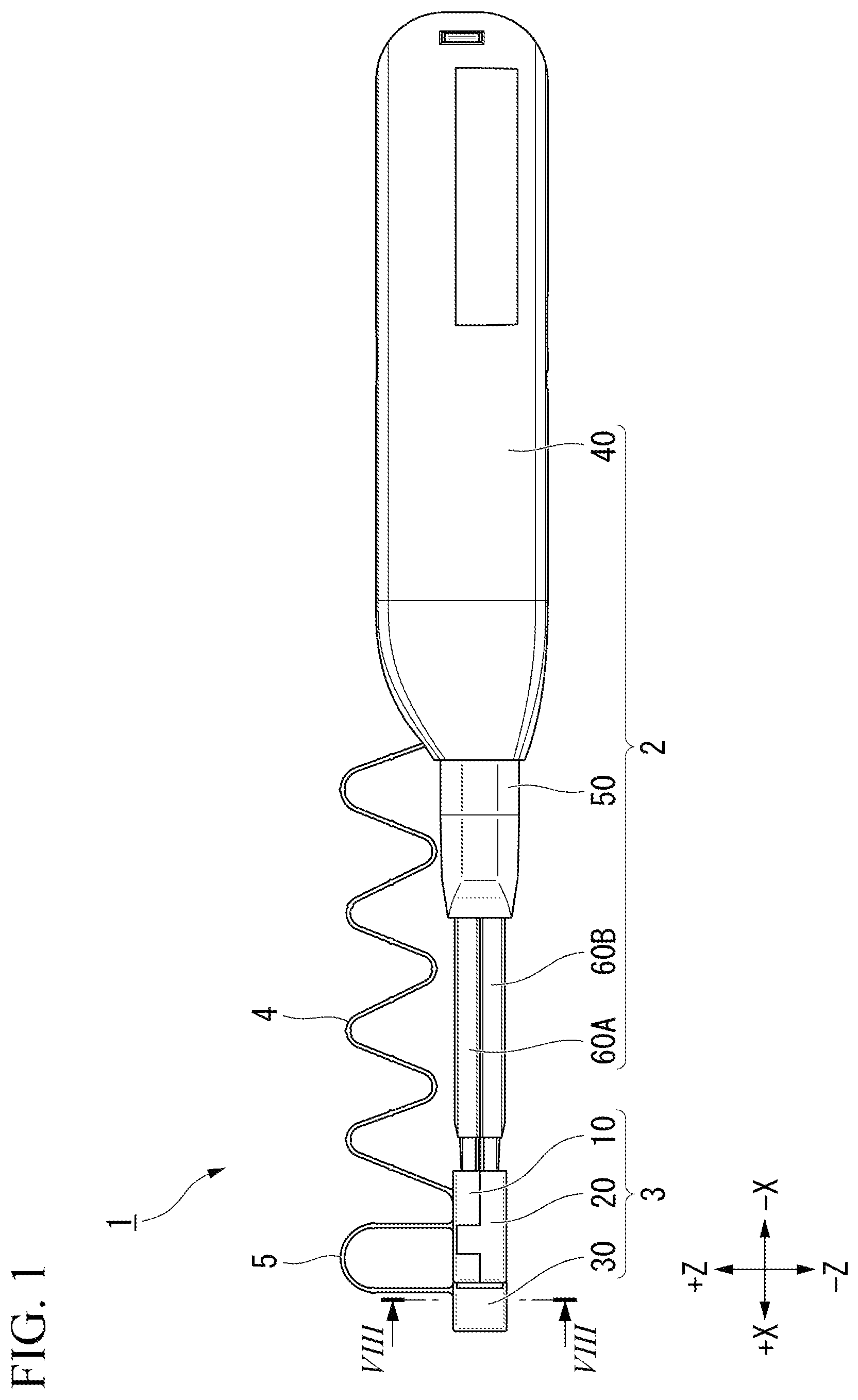
is an overall view of a cleaning tool with an attachment according to one or more embodiments.
A is a diagram showing a state in which an attachment is removed from the cleaning tool with an attachment according to one or more embodiments.
B is a diagram showing a state in which a plurality of nozzle members of A are away from each other.
is a partial cross-sectional view showing an internal structure of the cleaning tool according one or more embodiments.
is an exploded perspective view showing the internal structure of the cleaning tool according to one or more embodiments.
A is an enlarged view of the vicinity of the attachment of and shows a state in which the cap is removed.
B is a diagram showing a state in which a spacing between connection members of A is widened.
A is a cross-sectional view taken along line VIA-VIA of A .
B is a cross-sectional view taken along line VIB-VIB of B .
A is a cross-sectional view taken along line VIIA-VIIA of A .
B is a cross-sectional view taken along line VIIB-VIIB of A .
is a cross-sectional view taken along line VIII-VIII of .
A is a diagram showing a state in which an optical connector having a small pitch between ferrules is cleaned using the cleaning tool with an attachment according to one or more embodiments.
B is a diagram showing a state in which an optical connector having a large pitch between ferrules is cleaned using the cleaning tool with an attachment according to one or more embodiments.
DETAILED DESCRIPTION
Hereinafter, embodiments of the present invention will be described with reference to the drawings.
As shown in , a cleaning tool with an attachment 1 (attachment cleaning tool) includes a cleaning tool 2 and an attachment 3 that is attachable to and detachable from the cleaning tool 2 .
The cleaning tool 2 includes a main body portion 40 , an outer tubular body 50 , and a plurality of nozzle members 60 A, 60 B.
The attachment 3 includes a first connection member 10 , a second connection member 20 , and a cap 30 . The first connection member 10 and the second connection member 20 have a role of connecting the nozzle members 60 A, 60 B and the ferrule 81 to each other when an exposed ferrule 81 (described below) is cleaned by the cleaning tool 2 . The first connection member 10 and the second connection member 20 can move relative to each other within a predetermined range. The first connection member 10 is connected to the main body portion 40 by a first string portion 4 . The cap 30 is connected to the first connection member 10 by a second string portion 5 .
(Direction Definition)
In one or more embodiments, an XYZ Cartesian coordinate system is set and a positional relationship of each configuration is described. An X-axis direction is a direction in which the nozzle members 60 A, 60 B extend. A Z-axis direction is a direction in which a plurality of nozzle members 60 A, 60 B are arranged side by side. A Y-axis direction is a direction orthogonal to both the X-axis direction and the Z-axis direction.
Hereinafter, the X-axis direction is referred to as a longitudinal direction X, the Z-axis direction is referred to as a lateral direction Z, and the Y-axis direction is referred to as an orthogonal direction Y. Further, along the longitudinal direction X, the main body portion 40 side of the cleaning tool 2 is referred to as a −X side, and the attachment 3 side is referred to as a +X side. Along the lateral direction Z, the first nozzle member 60 A side is referred to as a +Z side, and the second nozzle member 60 B side is referred to as a −Z side. Along the orthogonal direction Y, one (first direction) side is referred to as a +Y side, and the other (second direction) side is referred to as a −Y side.
The nozzle members 60 A, 60 B are formed in a tubular shape extending along the longitudinal direction X. As shown in A , in the present specification, a central axis of the first nozzle member 60 A is referred to as a first central axis C 1 , and a central axis of the second nozzle member 60 B is referred to as a second central axis C 2 .
As shown in A, 2 B , the nozzle members 60 A, 60 B are provided to be movable closer to and away from each other in the lateral direction Z. The nozzle member 60 A has tip portion 61 A, intermediate portion 62 A, and base portion 63 A. The nozzle member 60 B has tip portion 61 B, intermediate portion 62 B, and base portion 63 B. The nozzle members 60 A, 60 B are formed in a symmetrical shape in the lateral direction Z. In the lateral direction Z, dimensions of the intermediate portions 62 A, 62 B are larger than dimensions of the tip portions 61 A, 61 B, and dimensions of the base portions 63 A, 63 B are larger than the dimensions of the intermediate portions 62 A, 62 B.
The outer tubular body 50 is formed in a tubular shape extending along the longitudinal direction X. The outer tubular body 50 covers the base portions 63 A, 63 B and −X side end portions of the intermediate portions 62 A, 62 B of the nozzle members 60 A, 60 B from the outside. The outer tubular body 50 has a large diameter portion 51 and a small diameter portion 52 . The small diameter portion 52 is located on the +X side of the large diameter portion 51 . The small diameter portion 52 is a portion of the outer tubular body 50 that opens toward the +X side. A dimension of an internal space of the small diameter portion 52 in the lateral direction Z is smaller than a dimension of an internal space of the large diameter portion 51 in the lateral direction Z.
As shown in A , in a state where the nozzle members 60 A, 60 B abut on each other, a gap in the lateral direction Z is formed between the intermediate portions 62 A, 62 B and the small diameter portion 52 and between the base portions 63 A, 63 B and the large diameter portion 51 . Therefore, as shown in B , the nozzle members 60 A, 60 B are movable away from each other until the intermediate portions 62 A, 62 B abut on an inner surface of the small diameter portion 52 or the base portions 63 A, 63 B abut on an inner surface of the large diameter portion 51 .
Since no partition or the like is provided inside the outer tubular body 50 , the nozzle members 60 A, 60 B are movable closer to each other to a position where the nozzle members 60 A, 60 B abut on each other, as shown in A .
As shown in , the main body portion 40 has a feeding mechanism M and an accommodating body 41 that accommodates the feeding mechanism M. The feeding mechanism M supplies and withdraws the cleaning bodies 6 A, 6 B with respect to head members 70 A, 70 B (refer to A, 7 B ) accommodated in the nozzle members 60 A, 60 B. A material of the cleaning bodies 6 A, 6 B is not particularly limited, and for example, it is possible to use a material obtained by processing a cleaning cloth (nonwoven fabric, woven cloth, or the like) into a thread shape (or string shape) or a tape shape. For example, the cleaning bodies 6 A, 6 B may be formed of ultrafine fibers such as polyester and nylon.
As shown in , the feeding mechanism M includes take-up reels 43 A, 43 B, gears 44 A, 44 B, and gear receiving portions 45 A, 45 B. Further, as shown in , the feeding mechanism M includes supply reels 46 A, 46 B, a support 47 , and holding portions 48 A, 48 B.
The support 47 supports the take-up reels 43 A, 43 B, the gears 44 A, 44 B, the gear receiving portions 45 A, 45 B, the supply reels 46 A, 46 B, and the holding portions 48 A, 48 B.
As shown in , a bottom wall 47 a , side walls 47 b , supply reel support shafts 47 c , 47 d , take-up reel support shafts 47 e , 47 f , and a holding protrusion 47 g are formed in the support 47 . The bottom wall 47 a is formed in a plate shape extending along the longitudinal direction X and the lateral direction Z, and the side wall 47 b extends from an outer peripheral edge of the bottom wall 47 a toward the −Y side. The supply reel support shafts 47 c , 47 d and the take-up reel support shafts 47 e , 47 f are located in a space surrounded by the bottom wall 47 a and the side wall 47 b . The supply reel support shafts 47 c , 47 d and the take-up reel support shafts 47 e , 47 f extend from the bottom wall 47 a toward the −Y side. The first supply reel support shaft 47 c rotatably supports the first supply reel 46 A, and the second supply reel support shaft 47 d rotatably supports the second supply reel 46 B.
The first take-up reel support shaft 47 e rotatably supports the first take-up reel 43 A and the first gear 44 A, and the second take-up reel support shaft 47 f rotatably supports the second take-up reel 43 B and the second gear 44 B. The holding portions 48 A, 48 B prevent the reels 43 A, 43 B, 46 A, 46 B inserted into the shafts 47 c to 47 f from falling off.
The holding protrusion 47 g protrudes from the side wall 47 b located at a −X-side end portion toward the −X side. The holding protrusion 47 g holds a biasing member 48 (refer to ). The biasing member 48 biases the support 47 toward the +X side.
The supply reels 46 A, 46 B include a body portion around which the cleaning bodies 6 A, 6 B are wrapped, and flange portions provided at both ends of the body portion. The supply reels 46 A, 46 B supply the cleaning bodies 6 A, 6 B toward the head members 70 A, 70 B. The take-up reels 43 A, 43 B wind up the cleaning bodies 6 A, 6 B that have returned to the main body portion 40 from the supply reels 46 A, 46 B via the head members 70 A, 70 B. The take-up reels 43 A, 43 B have body portions for winding the cleaning bodies 6 A, 6 B, and flange portions provided at both ends of the body portion.
As shown in , the accommodating body 41 includes a tubular case portion 41 a , and a pressing body 41 b located in the case portion 41 a and fixed by the case portion 41 a . The gear receiving portions 45 A, 45 B are formed in the pressing body 41 b and engage with the gears 44 A, 44 B. Insertion convex portions 41 c , 41 d that protrude toward the +Y side are formed in the case portion 41 a . The insertion convex portions 41 c , 41 d are inserted into spiral cam groove portions formed on the outer peripheral surfaces of the rotating shafts 49 A, 49 B. Therefore, when the rotating shafts 49 A, 49 B move in the longitudinal direction X with respect to the accommodating body 41 , the rotating shafts 49 A, 49 B rotate with respect to a central axis of each shaft. The first head member 70 A is attached to a tip of the first rotating shaft 49 A in a state where a rotation with respect to the first rotating shaft 49 A is restricted. The second head member 70 B is attached to a tip of the second rotating shaft 49 B in a state where a rotation with respect to the second rotating shaft 49 B is restricted. Therefore, when the rotating shafts 49 A, 49 B rotate, the head members 70 A, 70 B also rotates with respect to each central axis of the head member. The head members 70 A, 70 B may rotate with respect to the first central axis C 1 and the second central axis C 2 .
As shown in , a tubular body 42 is accommodated inside the accommodating body 41 . The tubular body 42 is formed in a tubular shape extending along the longitudinal direction X, and a portion of each of the rotating shafts 49 A, 49 B is inserted therein. The insertion convex portions 41 c , 41 d are inserted into the spiral cam groove portions of the rotating shafts 49 A, 49 B through an opening formed in the tubular body 42 .
As shown in A, 5 B , the first connection member 10 and the second connection member 20 are movable relative to each other in a direction of moving closer to or away from each other in the lateral direction Z. The first connection member 10 is attached to the tip portion 61 A of the first nozzle member 60 A, and the second connection member 20 is attached to the tip portion 61 B of the second nozzle member 60 B. The first connection member 10 and the second connection member 20 is formed in a box shape that opens toward the −X side. When the first connection member 10 and the second connection member 20 are attached to the nozzle members 60 A, 60 B, the tip portions 61 A, 61 B of the nozzle members 60 A, 60 B are inserted through the −X side opening portions of the connection members 10 , 20 .
As shown in A , the first connection member 10 has an upper wall portion 11 , a first right wall portion 12 , and a first left wall portion 13 . The upper wall portion 11 , the first right wall portion 12 , and the first left wall portion 13 form a first attachment portion 10 a . The first attachment portion 10 a is a portion attached to the tip portion 61 A of the first nozzle member 60 A (refer to A ). The upper wall portion 11 is formed in a plate shape extending along the longitudinal direction X and the orthogonal direction Y. The first right wall portion 12 extends from a −Y side end portion of the upper wall portion 11 toward the −Z side. The first left wall portion 13 extends from a +Y side end portion of the upper wall portion 11 toward the −Z side. The tip portion 61 A of the first nozzle member 60 A is accommodated inside a space formed by the upper wall portion 11 , the first right wall portion 12 , and the first left wall portion 13 . The upper wall portion 11 faces a first outer abutment surface 67 A of the tip portion 61 A in the lateral direction Z. The first outer abutment surface 67 A faces the +Z side. When the nozzle members 60 A, 60 B are away from each other in the lateral direction Z, a surface of the upper wall portion 11 facing the −Z side becomes a first outer regulation surface 11 a (outer regulation surface) that abuts on the first outer abutment surface 67 A.
An inner regulation portion 14 a protruding toward the +Y side is formed at a −Z side end portion of the first right wall portion 12 . An inner regulation portion 14 b protruding toward the −Y side is formed at a −Z side end portion of the first left wall portion 13 . Although not shown, the inner regulation portion 14 a and the inner regulation portion 14 b extend along the longitudinal direction X. A gap is provided between the inner regulation portion 14 a and the inner regulation portion 14 b in the orthogonal direction Y.
As shown in A , a first protruding portion 64 A that protrudes toward the −Z side is formed at the tip portion 61 A of the first nozzle member 60 A. The first protruding portion 64 A is provided at a central portion of the tip portion 61 A in the orthogonal direction Y. An inner abutment surface 65 A facing the −Z side is formed on the +Y side of the first protruding portion 64 A. An inner abutment surface 66 A facing the −Z side is formed on the −Y side of the first protruding portion 64 A. As shown in A , the first protruding portion 64 A is located between the inner regulation portion 14 a and the inner regulation portion 14 b in a state where the first nozzle member 60 A and the second nozzle member 60 B are close to each other. The inner abutment surface 65 A faces the inner regulation portion 14 b in the lateral direction Z, and the inner abutment surface 66 A faces the inner regulation portion 14 a in the lateral direction Z.
The second connection member 20 has a lower wall portion 21 , a second right wall portion 22 , and a second left wall portion 23 . The lower wall portion 21 , the second right wall portion 22 , and the second left wall portion 23 form a second attachment portion 20 a (refer to A ). The second attachment portion 20 a is a portion attached to the tip portion 61 B of the second nozzle member 60 B. The lower wall portion 21 is formed in a plate shape extending along the longitudinal direction X and the orthogonal direction Y. The second right wall portion 22 extends from a −Y side end portion of the lower wall portion 21 toward the +Z side. The second left wall portion 23 extends from a +Y side end portion of the lower wall portion 21 toward the +Z side. The tip portion 61 B of the second nozzle member 60 B is accommodated inside a space formed by the lower wall portion 21 , the second right wall portion 22 , and the second left wall portion 23 . The lower wall portion 21 faces the second outer abutment surface 67 B of the tip portion 61 B in the lateral direction Z. The second outer abutment surface 67 B faces the −Z side. When the nozzle members 60 A, 60 B are away from each other in the lateral direction Z, a surface of the lower wall portion 21 facing the +Z side becomes a second outer regulation surface 21 a (outer regulation surface) that abuts on the second outer abutment surface 67 B.
An inner regulation portion 24 a protruding toward the +Y side is formed at a +Z side end portion of the second right wall portion 22 . An inner regulation portion 24 b protruding toward the −Y side is formed at a +Z side end portion of the second left wall portion 23 . Although not shown, the inner regulation portion 24 a and the inner regulation portion 24 b extend along the longitudinal direction X. A gap is provided between the inner regulation portion 24 a and the inner regulation portion 24 b in the orthogonal direction Y.
As shown in A , a second protruding portion 64 B that protrudes toward the +Z side is formed at the tip portion 61 B of the second nozzle member 60 B. The second protruding portion 64 B is provided at a central portion of the tip portion 61 B in the orthogonal direction Y. An inner abutment surface 65 B facing the +Z side is formed on the +Y side of the second protruding portion 64 B. An inner abutment surface 66 B facing the +Z side is formed on the −Y side of the second protruding portion 64 B. As shown in A , the second protruding portion 64 B is located between the inner regulation portion 24 a and the inner regulation portion 24 b in a state where the first nozzle member 60 A and the second nozzle member 60 B are close to each other. The inner abutment surface 65 B faces the inner regulation portion 24 b in the lateral direction Z, and the inner abutment surface 66 B faces the inner regulation portion 24 a in the lateral direction Z.
As shown in A , a groove portion 12 a is formed in the first right wall portion 12 of the first connection member 10 . The groove portion 12 a is located at an intermediate portion of the first right wall portion 12 in the longitudinal direction X. The groove portion 12 a extends along the lateral direction Z and is open toward the −Z side. The groove portion 12 a is recessed from a surface of the first right wall portion 12 facing the −Y side toward the +Y side. As shown in A , a concave portion 12 b further recessed toward the +Y side is formed at a +Z side end portion of the groove portion 12 a.
As shown in A , a groove portion 13 a similar to the groove portion 12 a is also formed in the first left wall portion 13 of the first connection member 10 . Although not shown, the groove portion 13 a is located at intermediate portion of the first left wall portion 13 in the longitudinal direction X. The groove portion 13 a extends along the lateral direction Z and is open toward the −Z side. The groove portion 13 a is recessed from a surface of the first left wall portion 13 facing the +Y side toward the −Y side. As shown in A , a concave portion 13 b further recessed toward the −Y side is formed at a +Z side end portion of the groove portion 13 a.
Locking pieces 26 , 27 are formed in the second connection member 20 . The locking piece 26 extends from the second right wall portion 22 of the second connection member 20 toward the +Z side, and the locking piece 27 extends from the second left wall portion 23 of the second connection member 20 toward the +Z side. The locking piece 26 is located in the groove portion 12 a , and the locking piece 27 is located in the groove portion 13 a . The locking pieces 26 , 27 are slidable with respect to the groove portions 12 a , 13 a , respectively. A locking portion 26 a protruding toward the +Y side is formed at a +Z side end portion of the locking piece 26 . A locking portion 27 a protruding toward the −Y side is formed at a +Z side end portion of the locking piece 27 .
A locking protruding portion 12 c that is locked to the locking portion 26 a is formed in the groove portion 12 a , and a locking protruding portion 13 c that is locked to the locking portion 27 a is formed in the groove portion 13 a . At least a portion of the locking portion 26 a is located in the concave portion 12 b and faces the locking protruding portion 12 c in the lateral direction Z. At least a portion of the locking portion 27 a is located in the concave portion 13 b and faces the locking protruding portion 13 c in the lateral direction Z. When assembling the second connection member 20 to the first connection member 10 , the locking pieces 26 , 27 are made to enter the groove portions 12 a , 13 a from below. At this case, the locking pieces 26 , 27 are elastically deformed outward in the orthogonal direction Y, and when the locking portions 26 a , 27 a reach the concave portions 12 b , 13 b , the locking pieces 26 , 27 are deformed and restored.
With the above configuration, the first connection member 10 and the second connection member 20 can move relative to each other within a predetermined range in the lateral direction Z following relative movements of the nozzle members 60 A, 60 B.
For example, when the nozzle members 60 A, 60 B move to be away from each other in the lateral direction Z from the state shown in A , the first outer abutment surface 67 A of the first nozzle member 60 A and the first outer regulation surface 11 a of the first connection member 10 abut on each other, and the second outer abutment surface 67 B of the second nozzle member 60 B and the second outer regulation surface 21 a of the second connection member 20 abut on each other. As a result, following the nozzle members 60 A, 60 B, the first connection member 10 and the second connection member 20 move to be away from each other in the lateral direction Z.
When the first connection member 10 and the second connection member 20 move relative to each other by a predetermined amount to be away from each other in the lateral direction Z, the locking portions 26 a , 27 a abut on the locking protruding portions 12 c , 13 c as shown in B . Therefore, the relative movement of the first connection member 10 and the second connection member 20 exceeding a predetermined amount is restricted.
When the nozzle members 60 A, 60 B move closer to each other in the lateral direction Z from the state shown in B , the inner abutment surface 66 A of the first nozzle member 60 A abuts on the inner regulation portion 14 a and the inner abutment surface 65 A abuts on the inner regulation portion 14 b . Further, the inner abutment surface 66 B of the second nozzle member 60 B abuts on the inner regulation portion 24 a and the inner abutment surface 65 B abuts on the inner regulation portion 24 b . As a result, following the nozzle members 60 A, 60 B, the first connection member 10 and the second connection member 20 move to be close to each other in the lateral direction Z.
As shown in A , the first connection member 10 has a first front wall portion 16 and a first tubular portion 19 . The front wall portion 16 is formed to cover +X side end portions of the upper wall portion 11 , the first right wall portion 12 , and the first left wall portion 13 . The second connection member 20 has a second front wall portion 28 and a second tubular portion 29 . The front wall portion 28 is formed to cover +X side end portions of the lower wall portion 21 , the second right wall portion 22 , and the second left wall portion 23 .
The first tubular portion 19 protrudes from the first front wall portion 16 toward the +X side, and the second tubular portion 29 protrudes from the second front wall portion 28 toward the +X side. The first tubular portion 19 has a first tip tubular portion 19 a and a first press-fitting portion 19 b . The second tubular portion 29 has a second tip tubular portion 29 a and a second press-fitting portion 29 b . The tip tubular portions 19 a , 29 a are formed in a tubular shape and are located on the +X side of the press-fitting portions 19 b , 29 b.
As shown in A , an inclined surface 19 c is formed in a +X side opening portion of the first tip tubular portion 19 a . The inclined surface 19 c extends toward the −X side, and gradually approaches the first central axis C 1 . A first through hole 16 a connected to the space inside the first tubular portion 19 is formed in the first front wall portion 16 . The first through hole 16 a passes through the first front wall portion 16 in the longitudinal direction X. An abutment portion 15 A on which the tip portion 61 A abuts is formed inside the first connection member 10 . A first inner tubular portion 15 protruding from a −X-side opening portion of the first through hole 16 a toward the −X side is formed in the abutment portion 15 A. Inclined surfaces 15 a , 15 b are formed at a −X-side end portion of the first inner tubular portion 15 . The inclined surface 15 a is formed on an outer peripheral surface of the first inner tubular portion 15 . The inclined surface 15 a extends toward the −X side, and gradually approaches the first central axis C 1 . The inclined surface 15 b is formed on an inner peripheral surface of the first inner tubular portion 15 . The inclined surface 15 b extends toward the +X side, and gradually approaches the first central axis C 1 .
When the first head member 70 A moves toward the +X side, the first head member 70 A is guided by the inclined surface 15 b of the first inner tubular portion 15 . As a result, it is possible to introduce the first head member 70 A into the first inner tubular portion 15 smoothly. Further, when one ferrule 81 (refer to A, 9 B ) of an optical connector is inserted into the first tubular portion 19 , the inclined surface 19 c of the first tip tubular portion 19 a guides the ferrule 81 . As a result, it is possible to introduce the ferrule 81 into the first tip tubular portion 19 a smoothly.
Inner diameters of the first inner tubular portion 15 , the first through hole 16 a , and the first tubular portion 19 are substantially constant along the longitudinal direction X except for the portions where the inclined surfaces 19 c , 15 b are formed.
As shown in B , an inclined surface 29 c is formed in a +X side opening portion of the second tip tubular portion 29 a . The inclined surface 29 c extends toward the −X side, and gradually approaches the second central axis C 2 . A second through hole 28 a connected to a space inside the second tubular portion 29 is formed in the second front wall portion 28 . The second through hole 28 a pass through the second front wall portion 28 in the longitudinal direction X. An abutment portion 25 A on which the tip portion 61 B abuts is formed inside the second connection member 20 . A second inner tubular portion 25 that protrudes from a −X-side opening portion of the second through hole 28 a toward the −X side is formed in the abutment portion 25 A. Inclined surfaces 25 a , 25 b are formed at −X-side end portions of the second inner tubular portion 25 . The inclined surface 25 a is formed on an outer peripheral surface of the second inner tubular portion 25 . The inclined surface 25 a extends toward the −X side, and gradually approaches the second central axis C 2 . The inclined surface 25 b is formed on an inner peripheral surface of the second inner tubular portion 25 . The inclined surface 25 b extends toward the +X side, and gradually approaches the second central axis C 2 .
When the second head member 70 B moves toward the +X side, the second head member 70 B is guided by the inclined surface 25 b of the second inner tubular portion 25 . As a result, it is possible to introduce the second head member 70 B into the second inner tubular portion 25 smoothly. Further, when one ferrule 81 (refer to A, 9 B ) of the optical connector is inserted into the second tubular portion 29 , the inclined surface 29 c of the second tip tubular portion 29 a guides the ferrule. As a result, it is possible to introduce the ferrule 81 introduced into the second tip tubular portion 29 a smoothly.
Inner diameters of the second inner tubular portion 25 , the second through hole 28 a , and the second tubular portion 29 are substantially constant along the longitudinal direction X except for the portions where the inclined surfaces 29 c and 15 b are formed.
As shown in A , a first tip guide portion 68 A is formed at the tip portion 61 A of the first nozzle member 60 A. The first tip guide portion 68 A protrudes from the tip portion 61 A toward the +X side. The first tip guide portion 68 A is formed in a substantially bowl shape with a portion missing, and an inner peripheral surface thereof is a first inclined surface 69 A. The first inclined surface 69 A extends toward the −X side, and gradually approaches the first central axis C 1 . The inside of the first tip guide portion 68 A communicates with the inside of the first nozzle member 60 A. When the attachment 3 is attached to the cleaning tool 2 , at least a portion of the first inner tubular portion 15 enters the inside of the first tip guide portion 68 A. Then, the inclined surface 15 a of the first inner tubular portion 15 and the first inclined surface 69 A of the first nozzle member 60 A abut on each other, and thus, it is possible to align the positions between the first inner tubular portion 15 and the first nozzle member 60 A.
As shown in B , a second tip guide portion 68 B is formed at the tip portion 61 B of the second nozzle member 60 B. The second tip guide portion 68 B protrudes from the tip portion 61 B toward the +X side. The second tip guide portion 68 B is formed in a substantially bowl shape with a portion missing, and an inner peripheral surface thereof is an inclined surface 69 B. The inclined surface 69 B extends toward the −X side, and gradually approaches the second central axis C 2 . The inside of the second tip guide portion 68 B communicates with the inside of the second nozzle member 60 B. When the attachment 3 is attached to the cleaning tool 2 , at least a portion of the second inner tubular portion 25 enters the inside of the second tip guide portion 68 B. Then, the inclined surface 25 a of the second inner tubular portion 25 and the inclined surface 69 B of the second nozzle member 60 B abut on each other, and thus, it is possible to align the positions between the second inner tubular portion 25 and the second nozzle member 60 B.
The cap 30 is formed in a box shape that is open toward the −X side. By covering the tubular portions 19 , 29 with the cap 30 , it is possible to prevent dirt, dust, or the like from adhering to the tubular portions 19 , 29 . For example, the cap 30 is made of a resin.
As shown in , the press-fitting portions 19 b , 29 b of the tubular portions 19 , 29 are press-fitted into the inner surface of the cap 30 in the orthogonal direction Y. The press-fitting is made such that the cap 30 can be attached to and detached from the press-fitting portions 19 b , 29 b by force of a finger.
Meanwhile, the press-fitting portions 19 b , 29 b are not press-fitted into the inner surface of the cap 30 in the lateral direction Z. This is a configuration in consideration that the first connection member 10 and the second connection member 20 are movable relative to each other in the lateral direction Z. If the cap 30 is press-fitted into the press-fitting portions 19 b , 29 b in the lateral direction Z, it is necessary to press-fit the cap 30 with respect to the first connection member 10 and the second connection member 20 that are completely close to each other in the lateral direction Z, which makes it difficult to attach/detach the cap 30 . Instead of this, by press-fitting the cap 30 in the orthogonal direction Y, it is possible to press-fit the cap 30 even when the first connection member 10 and the second connection member 20 are not completely close to each other, and to attach/detach the cap 30 easily. Further, even when the first connection member 10 and the second connection member 20 are most away from each other in the lateral direction Z, it is possible to press-fit the cap 30 into the press-fitting portions 19 b , 29 b.
A, 9 B show an example of a use state of the cleaning tool with an attachment 1 according to one or more embodiments. The cleaning tool with an attachment 1 is capable of cleaning the connection end surfaces 81 a of optical connectors 80 A, 80 B from which the ferrules 81 are exposed. Although not shown, an optical fiber is accommodated inside each ferrule 81 , and an end surface of the optical fiber is exposed from the connection end surface 81 a.
The optical connector 80 A shown in A and the optical connector 80 B shown in B have different pitches between the two ferrules 81 . A pitch P 1 between the two ferrules of the optical connector 80 A is, for example, about 3.1 mm, and a pitch P 2 between the two ferrules of the optical connector 80 B is, for example, about 3.8 mm. The pitches P 1 , P 2 may be appropriately changed according to a standard of the optical connector or the like.
When the cleaning tool with an attachment 1 is used, as shown in A, 9 B , by moving the nozzle members 60 A, 60 B closer to each other or away from each other according to the pitches P 1 , P 2 which are different depending on the optical connectors 80 A, 80 B, the positions of the tubular portions 19 , 29 are aligned with the positions of the ferrules 81 . Then, the ferrules 81 are inserted into the tubular portions 19 , 29 , respectively, and the cleaning tool 2 is pushed toward the optical connectors 80 A, 80 B. As a result, the head members 70 A, 70 B in the nozzle members 60 A, 60 B protrude from the tip portions 61 A, 61 B and are introduced into the tubular portions 19 , 29 . Within each of the tubular portions 19 , 29 , the positions of the central axes of the ferrules 81 and the head members 70 A, 70 B are aligned. As a result, the head members 70 A, 70 B are pressed against the connection end surfaces 81 a , respectively, and the cleaning bodies 6 A, 6 B wrapped around the head members 70 A, 70 B abuts on the connection end surfaces 81 a , respectively. Thus, it is possible to clean the connection end surfaces 81 a by the cleaning bodies 6 A, 6 B.
As the cleaning tool 2 is pushed in, the head members 70 A, 70 B rotate with respect to the central axis of each head portion, and the cleaning bodies 6 A, 6 B are fed from the supply reels 46 A, 46 B to take-up reels 43 A, 43 B by the operation of the feeding mechanism M. By rotating the head members 70 A, 70 B, the connection end surface 81 a is more reliably cleaned. Further, portions of the cleaning bodies 6 A, 6 B to which dirt has adhered are wrapped on the take-up reels 43 A, 43 B, and new cleaning bodies 6 A, 6 B having no dirt adhered are supplied from the supply reels 46 A, 46 B to the head members 70 A, 70 B. As a result, it is possible to repeatedly use the cleaning tool with an attachment 1 .
Meanwhile, when cleaning the optical connector (optical adapter) in a state where the ferrules 81 are not exposed and are located in the connector accommodating hole, the attachment 3 is removed from the cleaning tool 2 and the nozzle members 60 A, 60 B are inserted into the connector accommodating holes. In this case, it is possible to align the positions between the nozzle members 60 A, 60 B and the ferrules by the connector accommodating holes. Further, for example, by inserting the end portion of the ferrules into the tip guide portions 68 A, 68 B, it is possible to determine the positions of the nozzle members 60 A, 60 B and the ferrules more accurately.
As described above, the cleaning tool with an attachment 1 according to one or more embodiments includes the cleaning tool 2 including the plurality of nozzle members 60 A, 60 B provided to be movable closer to each other and away from each other in the lateral direction Z, and the attachment 3 which is attached to the cleaning tool 2 and is detachable from the cleaning tool 2 . Further, the attachment 3 includes the plurality of connection members 10 , 20 , and the plurality of connection members 10 , 20 respectively include: the attachment portions 10 a , 20 a attached to the tip portions 61 A, 61 B of the nozzle members 60 A, 60 B; and the tubular portions 19 , 29 which respectively protrude from the attachment portions 10 a , 20 a in the longitudinal direction X and into which the ferrule 81 is inserted. Then, the plurality of connection members 10 , 20 move following the relative movement of the nozzle members 60 A, 60 B in the lateral direction Z. As a result, it is possible to simultaneously clean the plurality of connection end surfaces 81 a included in one of the optical connectors 80 A, 80 B from which the plurality of ferrules 81 are exposed by the cleaning tool with the attachment 1 having the above configuration. Further, even when the optical connectors 80 A, 80 B have different pitches between the plurality of ferrules 81 , it is possible clean the optical connectors 80 A, 80 B with the same cleaning tool with an attachment 1 . Therefore, it is possible to save a trouble of changing the cleaning tool with the attachment 1 by the optical connectors 80 A, 80 B having different pitches between the ferrules 81 , and to perform efficient cleaning.
Further, the tip guide portions 68 A, 68 B protruding toward the tubular portions 19 , 29 (+X side) are formed at the tip portions 61 A, 61 B of the plurality of nozzle members 60 A, 60 B. Moreover, the abutment portions 15 A, 25 A on which the tip portions 61 A, 61 B abut are formed on the inner surfaces of the attachment portions 10 a , 20 a , and the inner tubular portions 15 , 25 are formed on the abutment portions 15 A, 25 A, the inner tubular portions 15 , 25 that protrude toward the nozzle members 60 A, 60 B (−X side) and enters the insides of the tip guide portions 68 A, 68 B to be in contact with the tip guide portions 68 A, 68 B. With this configuration, it is possible to align the positions between the tip portions 61 A, 61 B of the nozzle members 60 A, 60 B and the tubular portions 19 , 29 easily. Therefore, when the head members 70 A, 70 B protrude from the nozzle members 60 A, 60 B, it is possible to introduce the head members 70 A, 70 B into the tubular portions 19 , 29 smoothly.
Further, the first inclined surfaces 69 A, 69 B that incline so as to approach the central axes C 1 , C 2 of the nozzle members 60 A, 60 B toward the accommodating body 41 (−X side) in the longitudinal direction X are formed on the inner surfaces of the tip guide portions 68 A, 68 B, and the second inclined surfaces 15 a , 25 a that incline so as to approach the central axes C 1 , C 2 toward the accommodating body 41 in the longitudinal direction X are formed on the outer peripheral surfaces of the inner tubular portions 15 , 25 . With this configuration, when the attachment 3 is attached to the cleaning tool 2 , it is possible to introduce the inner tubular portions 15 , 25 into the tip guide portions 68 A, 68 B more smoothly. Therefore, it is possible to align the positions between the tip portions 61 A, 61 B of the nozzle members 60 A, 60 B and the tubular portions 19 , 29 more reliably.
Further, the outer regulation surfaces 11 a , 21 a are respectively formed in the plurality of connection members 10 , 20 , the outer regulation surfaces 11 a , 21 a that abut on the outer abutment surfaces 67 A, 67 B of the nozzle members 60 A, 60 B facing outward in the lateral direction Z when the plurality of nozzle members 60 A, 60 B move away from each other in the lateral direction Z. With this configuration, when the nozzle members 60 A, 60 B move relative to each other to be away from each other, it is possible to move the nozzle members 60 A, 60 B following the connection members 10 , 20 more reliably.
Further, the inner regulation portions 14 a , 14 b , 24 a , 24 b are formed in the plurality of connection members 10 , 20 , the inner regulation portions 14 a , 14 b , 24 a , 24 b that abut on the inner abutment surfaces 65 A, 65 B, 66 A, 66 B of the nozzle members 60 A, 60 B facing inward in the lateral direction Z when the plurality of nozzle members 60 A, 60 B move closer to each other in the lateral direction Z. With this configuration, when the nozzle members 60 A, 60 B move relative to each other to be closer to each other, it is possible to move the nozzle members 60 A, 60 B following the connection members 10 , 20 more reliably.
Further, the attachment 3 has the cap 30 provided to be attachable to and detachable from the first connection member 10 and the second connection member 20 . The cap 30 is not press-fitted into the press-fitting portions 19 b , 29 b of the tubular portions 19 , 29 in the lateral direction Z, and is press-fitted into the press-fitting portions 19 b , 29 b in the orthogonal direction Y orthogonal to the lateral direction Z and the longitudinal direction X. With this configuration, it is possible to press-fit the cap 30 into the press-fitting portions 19 b , 29 b even in the state where the first connection member 10 and the second connection member 20 are not completely close to each other, and thus, the attachment/detachment operation of the cap 30 is more easily performed.
Further, the second connection member 20 includes; the pair of locking pieces 26 , 27 which protrude in the lateral direction Z and are disposed at an interval in the orthogonal direction Y; and the pair of the locking portions 26 a , 27 a protruding inward in the orthogonal direction Y from each of the pair of locking pieces 26 , 27 . Then, the first connection member 10 includes the pair of groove portions 12 a , 13 a on which the pair of locking pieces 26 , 27 respectively slide, and the pair of locking protruding portions 12 c , 13 c which are respectively locked to the pair of locking portions 26 a , 27 a . With this configuration, it is possible to make the first connection member 10 and the second connection member 20 move relative to each other, and to prevent the first connection member 10 and the second connection member 20 from unexpectedly falling off. Further, by elastically deforming the locking pieces 26 , 27 , it is possible to assemble the second connection member 20 to the first connection member 10 .
The attachment 3 according to one or more embodiments is the attachment 3 mounted on the cleaning tool 2 for cleaning the connection end surfaces 81 a of the optical connectors 80 A, 80 B by the cleaning bodies 6 A, 6 B and includes the plurality of connection members 10 , 20 which are provided to be movable to closer to each other and away from each other, the plurality of connection members 10 , 20 includes the attachment portions 10 a , 20 a attached to the tip portions 61 A, 61 B of the nozzle members 60 A, 60 B of the cleaning tool 2 and the tubular portions 19 , 29 which protrude from the attachment portions 10 a , 20 a and into which the ferrule 81 is inserted, and the attachment 3 is attached to the tip portions 61 A, 61 B of the nozzle members 60 A, 60 B and is detachable from the tip portions 61 A, 61 B of the nozzle members 60 A, 60 B.
By attaching the attachment 3 to the cleaning tool 2 including a plurality of nozzle members 60 A, 60 B that is movable relative to each other, it is possible to align the positions between the plurality of exposed ferrules 81 and the plurality of nozzle members 60 A, 60 B with each other.
Further, since the attachment 3 is attachable and detachable, it is possible to clean the connection end surface 81 a by the cleaning tool 2 regardless of whether or not the ferrules 81 are located in the connector accommodating holes.
In the cleaning tool 2 according to one or more embodiments, the plurality of nozzle members 60 A, 60 B are provided to be movable closer to each other and away from each other in the lateral direction Z in which the plurality of nozzle members 60 A, 60 B are arranged, the tip guide portions 68 A, 68 B which protrude in the longitudinal direction of the nozzle members 60 A, 60 B and of which the insides communicate with the insides of the nozzle members 60 A, 60 B are formed at the tip portions 61 A, 61 B of the plurality of nozzle members 60 A, 60 B, and thus, the attachment 3 is attachable to and detachable from the tip portions 61 A, 61 B of the nozzle members 60 A, 60 B.
According to the cleaning tool 2 having the above configuration, by attaching the attachment 3 , it is possible to align the positions between the plurality of exposed ferrules 81 and the plurality of nozzle members 60 A and 60 B. Further, in the state where the attachment 3 is removed, it is possible to more accurately determine the positions of the nozzle members 60 A, 60 B and the ferrule 81 , for example, by inserting the end portion of the ferrule 81 into the tip guide portions 68 A, 68 B.
The scope of the present invention is not limited to the above-described embodiments, and various modifications can be made without departing from a spirit of the present invention.
For example, as described above, in one or more embodiments, the number of nozzle members 60 A, 60 B is two, but the number of nozzle members may be three or more. Similarly, in one or more embodiments, the number of connection members 10 , 20 included in the attachment 3 is two, but the number of connection members may be three or more. Also in these cases, the nozzle members are provided to be movable closer to and away from each other in the lateral direction Z, and each of the plurality of connection members attached to the nozzle members moves following the relative movement of the nozzle members in the lateral direction Z. Accordingly, the same action and effect as those of the above-described embodiments can be obtained.
When the number of connection members is 3 or more, for example, a third connection member may be provided on the +Z side of the first connection member 10 . Then, the third connection member may include the pair of locking pieces extending toward the −Z side, the pair of locking protruding portions locked to the locking portions formed on the pair of locking pieces, and the pair of groove portions on which the pair of locking pieces slides. The pair of locking protruding portions and the pair of groove portions may be provided at positions deviated from the groove portion 12 a , 13 a of the first connection member 10 in the longitudinal direction X. With such a configuration, it is possible to prevent the three or more connection members from falling off while allowing the three or more connection members to move relative to each other in the lateral direction Z.
Further, as described above, in one or more embodiments, the structure is adopted in which the feeding mechanism M is operated by movement of the accommodating body 41 to feed and move the cleaning bodies 6 A, 6 B, but the structure for feeding and moving the cleaning bodies 6 A, 6 B is not limited to this. For example, it is possible to adopt a configuration in which an operator manually operates the take-up reel, a configuration in which a motor for operating the take-up reel is built-in, or the like.
Although the disclosure has been described with respect to only a limited number of embodiments, those skilled in the art, having benefit of this disclosure, will appreciate that various other embodiments may be devised without departing from the scope of the present invention. Accordingly, the scope of the invention should be limited only by the attached claims.
REFERENCE SIGNS LIST
•
• 1 : Cleaning tool with attachment • 2 : Cleaning tool • 3 : Attachment • 6 A, 6 B: Cleaning body • 10 : First connection member • 10 a , 20 a : Attachment portion • 11 a , 21 a : Outer regulation surface • 12 a , 13 a : Groove portion • 12 c , 13 c : Locking protruding portion • 14 a , 14 b , 24 a , 24 b : Inner regulation portion • 15 , 25 : Inner tubular portion • 15 A, 25 A: Abutment portion • 15 a , 25 a : Second inclined surface • 19 , 29 : Tubular portion • 20 : Second connection member • 26 , 27 : Locking piece • 26 a , 27 a : Locking portion • 30 : Cap • 41 : Accommodating body • 60 A, 60 B: Nozzle member • 61 A, 61 B: Tip portion • 65 A, 65 B, 66 A, 66 B: Inner abutment surface • 67 A, 67 B: Outer abutment surface • 68 A, 68 B: Tip guide portion • 69 A, 69 B: First inclined surface • 70 A, 70 B: Head member • 80 A, 80 B: Optical connector • 81 : Ferrule • 81 a : Connection end surface • C 1 , C 2 : Central axis • M: Feeding mechanism • X: Longitudinal direction • Y: Orthogonal direction • Z: Lateral direction
Figures (9)
Citations
This patent cites (11)
- USD681292
- US20030169991
- US20100043159
- US20120066849
- US1798993
- US102380484
- US103299225
- US2010-164997
- US2011-150083
- US2011-186082
- US5238873