Resin-molded Stator, Outer Rotor-type Motor, Air Blower, and Air Conditioning Apparatus
Abstract
In resin molding, potting to be conducted with a male terminal bonded to a female terminal increases costs and processes. A resin-molded stator includes a coil, a female terminal, a male terminal, and an insulator. The female terminal includes a female terminal connection portion and a spring portion. The male terminal includes a male terminal connection portion, a wire connection portion, and a second surface contact portion. The insulator accommodates the female terminal connection portion, the spring portion, and the male terminal connection portion, and electrically connects the male terminal to the female terminal. The second surface contact portion faces a second surface of the insulator wall.
Claims (20)
1. A stator apparatus to be subjected to resin molding, the stator apparatus comprising: a coil; a female terminal including a female terminal connection portion and a spring portion, the female terminal electrically connected to the coil; a male terminal for motor connection, including a male terminal connection portion and a wire connection portion; and an insulator including an accommodation portion accommodating the female terminal connection portion, the spring portion, and the male terminal connection portion and electrically connecting the male terminal to the female terminal, wherein the insulator includes an insulator wall which is a one-directional wall that forms the accommodation portion, a first surface of the insulator wall is in contact with the female terminal connection portion, the male terminal connection portion is pressed against the female terminal connection portion by the spring portion, and is electrically connected to the female terminal connection portion, the wire connection portion extends opposite to the first surface of the insulator wall, the male terminal further includes a second surface contact portion, and the second surface contact portion faces a second surface of the insulator wall, the second surface corresponding to a reverse side of the insulator wall with respect to the first surface.
Show 19 dependent claims
2. The stator apparatus according to claim 1 , wherein the second surface contact portion is configured to come into contact with the second surface to inhibit a change in orientation of the male terminal connection portion at least when a force is exerted on the wire connection portion in the resin molding.
3. The stator apparatus according to claim 2 , wherein the insulator wall is sandwiched between the male terminal connection portion and the second surface contact portion.
4. The stator apparatus according to claim 2 , wherein the second surface contact portion corresponds to a wire barrel portion of the male terminal.
5. The stator apparatus according to claim 2 , wherein the insulator further includes a support surface in addition to the second surface of the insulator wall, and the support surface is configured to support the male terminal when a force is exerted on the wire connection portion in the resin molding.
6. An outer rotor-type motor comprising: the stator apparatus according to claim 2 , said stator apparatus having been resin-molded to form a resin-molded stator; and a rotor configured to rotate radially outside the resin-molded stator.
7. An air blower comprising: the outer rotor-type motor according to claim 6 ; and a fan configured to rotate with power from the outer rotor-type motor.
8. The stator apparatus according to claim 1 , wherein the insulator wall is sandwiched between the male terminal connection portion and the second surface contact portion.
9. The stator apparatus according to claim 8 , wherein the second surface contact portion corresponds to a wire barrel portion of the male terminal.
10. The stator apparatus according to claim 8 , wherein the insulator further includes a support surface in addition to the second surface of the insulator wall, and the support surface is configured to support the male terminal when a force is exerted on the wire connection portion in the resin molding.
11. An outer rotor-type motor comprising: the stator apparatus according to claim 8 , said stator apparatus having been resin-molded to form a resin-molded stator; and a rotor configured to rotate radially outside the resin-molded stator.
12. An air blower comprising: the outer rotor-type motor according to claim 11 ; and a fan configured to rotate with power from the outer rotor-type motor.
13. The stator apparatus according to claim 1 , wherein the second surface contact portion corresponds to a wire barrel portion of the male terminal.
14. The stator apparatus according to claim 13 , wherein the insulator further includes a support surface in addition to the second surface of the insulator wall, and the support surface is configured to support the male terminal when a force is exerted on the wire connection portion in the resin molding.
15. An outer rotor-type motor comprising: the stator apparatus according to claim 13 , said stator apparatus having been resin-molded to form a resin-molded stator; and a rotor configured to rotate radially outside the resin-molded stator.
16. The stator apparatus according to claim 1 , wherein the insulator further includes a support surface in addition to the second surface of the insulator wall, and the support surface is configured to support the male terminal when a force is exerted on the wire connection portion in the resin molding.
17. An outer rotor-type motor comprising: the stator apparatus according to claim 16 , said stator apparatus having been resin-molded to form a resin-molded stator; and a rotor configured to rotate radially outside the resin-molded stator.
18. An outer rotor-type motor comprising: the stator apparatus according to claim 1 , said stator apparatus having been resin-molded to form a resin-molded stator; and a rotor configured to rotate radially outside the resin-molded stator.
19. An air blower comprising: the outer rotor-type motor according to claim 18 ; and a fan configured to rotate with power from the outer rotor-type motor.
20. An air conditioning apparatus comprising the air blower according to claim 19 .
Full Description
Show full text →
CROSS REFERENCE TO RELATED APPLICATIONS
This application is a Continuation of PCT International Application No. PCT/JP2021/032757, filed on Sep. 7, 2021, which claims priority under 35 U.S.C. 119(a) to Patent Application No. 2020-151682, filed in Japan on Sep. 9, 2020, all of which are hereby expressly incorporated by reference into the present application.
TECHNICAL FIELD
The present disclosure relates to a resin-molded stator, an outer rotor-type motor, an air blower, and an air conditioning apparatus.
BACKGROUND ART
Patent Literature 1 (JP 2003-163040 A) discloses a technique, in electrically connecting a male terminal to a female terminal, to subject an electrical connection portion between the male terminal and female terminal to potting with the male terminal bonded to the female terminal, so as to avoid a conduction failure owing to a gap between the male terminal and the female terminal.
SUMMARY
A first aspect is directed to a resin-molded stator to be subjected to resin molding. The resin-molded stator includes a coil, a female terminal, a male terminal, and an insulator. The female terminal includes a female terminal connection portion and a spring portion. The female terminal is electrically connected to the coil. The male terminal includes a male terminal connection portion and a wire connection portion. The male terminal is for motor connection. The insulator includes an accommodation portion. The accommodation portion accommodates the female terminal connection portion, the spring portion, and the male terminal connection portion, and electrically connects the male terminal to the female terminal. The insulator includes an insulator wall which is a one-directional wall that forms the accommodation portion. A first surface of the insulator wall is in contact with the female terminal connection portion. The male terminal connection portion is pressed against the female terminal connection portion by the spring portion, and is electrically connected to the female terminal connection portion. The wire connection portion extends opposite to the first surface of the insulator wall. The male terminal further includes a second surface contact portion. The second surface contact portion faces a second surface of the insulator wall, the second surface corresponding to a reverse side of the insulator wall with respect to the first surface.
BRIEF DESCRIPTION OF THE DRAWINGS
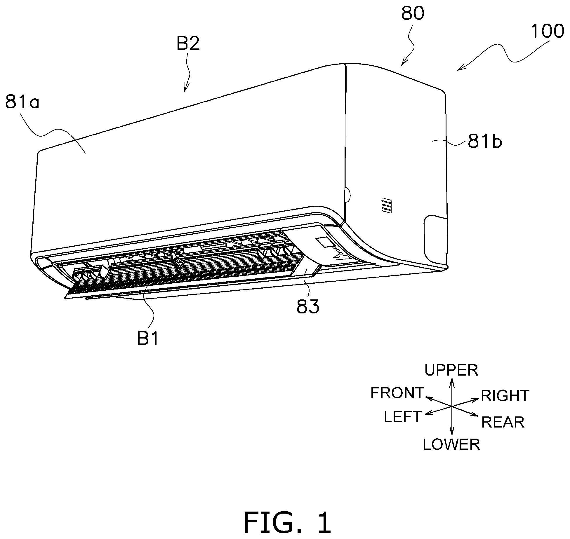
is an external view of an air-conditioning indoor unit.
is a longitudinal sectional view of the air-conditioning indoor unit.
is a front view of a frame and the like of the air-conditioning indoor unit.
is a longitudinal sectional view of an outer rotor-type motor.
is a perspective view of the resin-molded stator after resin molding, the resin-molded stator seen from its upper left side.
is a sectional view of the resin-molded stator before the resin molding.
is a perspective view of an insulator.
is a view of how a female terminal and a male terminal are accommodated in an accommodation portion of the insulator.
is a perspective view of the male terminal.
is a sectional view of the accommodation portion of the insulator before the resin molding in the resin-molded stator according to an embodiment.
is a sectional view of an accommodation portion of an insulator before resin molding in an existing product.
is a view of a flow of a resin in the resin molding.
is a view of a wire connection portion of the male terminal in the resin-molded stator according to the embodiment with a pressure of the flowing resin applied to the wire connection portion.
is a view of a wire connection portion of a male terminal in the existing product with a pressure of a flowing resin applied to the wire connection portion.
is a view of an insulator pedestal placed on a second surface side of the insulator wall.
is a sectional view of an accommodation portion of an insulator before resin molding in a resin-molded stator according to Modification 1B.
DESCRIPTION OF EMBODIMENTS
In the following description, the terms that represent directions and positional relationships, such as “front”, “rear”, “upper”, “lower”, “right”, and “left”, are defined with directions “front”, “rear”, “upper”, “lower”, “right”, and “left” indicated by arrows in and the like unless otherwise specified.
(1) Configuration of Air Conditioning Apparatus
An air conditioning apparatus 100 includes an air-conditioning indoor unit 80 and an air-conditioning outdoor unit (not illustrated). The air-conditioning indoor unit 80 and the air-conditioning outdoor unit (not illustrated) achieve a vapor compression refrigerant cycle to carry out air conditioning operations for, for example, cooling, heating, and dehumidifying a target space. is an external view of the air-conditioning indoor unit 80 . is a longitudinal sectional view of the air-conditioning indoor unit 80 .
(1-1) Configuration of Air-Conditioning Indoor Unit
The air-conditioning indoor unit 80 according to this embodiment is a wall-hung unit and is used with its rear surface hung on a wall of the target space. The terms “front”, “rear”, “upper”, “lower”, “right”, and “left” indicated by the arrows in represent directions of the air-conditioning indoor unit 80 that is hung on the wall and is seen from its front side toward the wall.
As illustrated in , the air-conditioning indoor unit 80 mainly includes a frame 81 , a front surface panel 81 a , a main body cover 81 b , a heat exchanger 82 , a flap 83 , and an air blower 70 . The heat exchanger 82 and the air blower 70 are supported by the frame 81 and are covered with the front surface panel 81 a and the main body cover 81 b.
The main body cover 81 b has in its upper surface an intake port B 2 , and also has in its lower surface a blow-out port B 1 . The flap 83 is disposed at the blow-out port B 1 .
A refrigerant flows inside a heat transfer tube of the heat exchanger 82 . The refrigerant exchanges heat with air around the heat exchanger 82 . The air blower 70 takes in air through the intake port B 2 . The air flows from the intake port B 2 toward the heat exchanger 82 and then passes through the air blower 70 . The air is thus blown out of the air-conditioning indoor unit 80 toward the target space through the blow-out port B 1 . The direction of the air to be blown out of the air-conditioning indoor unit 80 is changeable by changing the position of the flap 83 .
(1-2) Configuration of Air Blower
The air blower 70 mainly includes an outer rotor-type motor 50 and a fan 60 . The outer rotor-type motor 50 will be described in detail later. The fan 60 is configured to rotate with power from the outer rotor-type motor 50 . In this embodiment, the fan 60 is a cross-flow fan 60 a . The cross-flow fan 60 a is a fan 60 including a fan rotor 61 having a cylindrical shape and extending long to left and right. The outer rotor-type motor 50 that rotates the fan rotor 61 is disposed on a right side of the cross-flow fan 60 a . is a front view of the frame 81 and the like of the air-conditioning indoor unit 80 . As illustrated in , the cross-flow fan 60 a is disposed in a fan accommodation space 84 A in the frame 81 illustrated in . The outer rotor-type motor 50 is disposed in a motor accommodation space 84 B in the frame 81 illustrated in . The frame 81 includes, for example, a rear surface portion 85 a serving as a drain pan, a scroll portion 85 b located below the cross-flow fan 60 a , and a first motor support portion 85 c supporting the outer rotor-type motor 50 . The frame 81 is made of a resin.
(1-3) Configuration of Outer Rotor-Type Motor
is a longitudinal sectional view of the outer rotor-type motor 50 . As illustrated in , the outer rotor-type motor 50 mainly includes a resin-molded stator 10 and a rotor 40 . The resin-molded stator 10 will be described in detail later. The rotor 40 includes a magnet 46 b and a magnet holding portion 46 a holding the magnet 46 b . The magnet holding portion 46 a is a cylindrical outer periphery of the rotor 40 . The magnet holding portion 46 a is located in a first space S 11 having a ring shape. The first space S 11 is located radially outside the resin-molded stator 10 . A motor rotation shaft 49 is fixed to an inner periphery of the rotor 40 . Although not illustrated in , the fan rotor 61 of the cross-flow fan 60 a is fixed to a left end of the motor rotation shaft 49 . As illustrated in , a bearing 48 is disposed between an inner periphery of the resin-molded stator 10 and the motor rotation shaft 49 . The motor rotation shaft 49 and the rotor 40 are supported by the resin-molded stator 10 with the bearing 48 .
is a perspective view of the resin-molded stator 10 seen from its upper left side. As illustrated in , the resin-molded stator 10 includes a mount foot 15 . As illustrated in , the outer rotor-type motor 50 is fixed to the first motor support portion 85 c and a second motor support portion 85 d with a seal member 41 wound around the mount foot 15 of the resin-molded stator 10 . The outer rotor-type motor 50 is sealed with a sealing member 42 .
Electric current, when passing through a coil 11 of the resin-molded stator 10 , generates a magnetic field, so that the rotor 40 including the magnet 46 b rotates radially outside the resin-molded stator 10 . The motor rotation shaft 49 thus rotates and, accordingly, the fan rotor 61 of the cross-flow fan 60 a fixed to the motor rotation shaft 49 also rotates.
(2) Specific Configuration of Resin-Molded Stator
The resin-molded stator 10 is subjected to resin molding. is a sectional view of the resin-molded stator 10 before the resin molding.
The resin-molded stator 10 mainly includes the coil 11 , a female terminal 12 , a male terminal 13 , and an insulator 14 .
(2-1) Insulator
As illustrated in , the resin-molded stator 10 includes a plurality of insulators 14 . is a perspective view of the insulator 14 . As illustrated in , the insulator 14 includes a coil holding portion 14 a around which the coil 11 is wound. It should be noted that the coil 11 is grayed in . The insulator 14 also includes an accommodation portion 14 b . The accommodation portion 14 b accommodates the female terminal 12 and the male terminal 13 , and electrically connects the male terminal 13 to the female terminal 12 . is a view of how the female terminal 12 and the male terminal 13 are accommodated in the accommodation portion 14 b of the insulator 14 . As illustrated in , the female terminal 12 and the male terminal 13 are accommodated in the accommodation portion 14 b in a direction indicated by a solid-line arrow in . The insulator 14 includes an insulator wall 14 c which is a one-directional wall that forms the accommodation portion 14 b . In , the insulator wall 14 c corresponds to a wall that is not illustrated, but is indicated by a dotted-line arrow.
(2-2) Coil
As illustrated in , the coil 11 is wound around the coil holding portion 14 a of the insulator 14 . A material for the coil 11 , for example, aluminum or copper.
(2-3) Female Terminal
As illustrated in , the female terminal 12 includes a female terminal connection portion 12 a and a spring portion 12 b . The female terminal 12 is electrically connected to the coil 11 . Functions of the female terminal connection portion 12 a and spring portion 12 b in electrically connecting the male terminal 13 to the female terminal 12 will be described later.
(2-4) Male Terminal
The male terminal 13 is used for motor connection. is a perspective view of the male terminal 13 . As illustrated in , the male terminal 13 includes a male terminal connection portion 13 a and a wire connection portion 13 b . A function of the male terminal connection portion 13 a in electrically connecting the male terminal 13 to the female terminal 12 will be described later. The wire connection portion 13 b includes a wire barrel portion 13 b 1 and an insulation barrel portion 13 b 2 . The wire barrel portion 13 b 1 is the portion that crimps a core of a wire. The insulation barrel portion 13 b 2 is the portion that crimps a covered wire.
is a sectional view of the accommodation portion 14 b of the insulator 14 before the resin molding in the resin-molded stator 10 according to this embodiment. As illustrated in , the wire connection portion 13 b extends opposite to a first surface 14 c 1 of the insulator wall 14 c.
The male terminal 13 further includes a second surface contact portion 13 c . As illustrated in , the insulator wall 14 c is sandwiched between the male terminal connection portion 13 a and the second surface contact portion 13 c . In this embodiment, the second surface contact portion 13 c corresponds to the wire barrel portion 13 b 1 of the male terminal 13 .
(2-5) Electrical Connection in Accommodation Portion of Insulator
As illustrated in , the accommodation portion 14 b of the insulator 14 accommodates the female terminal connection portion 12 a , the spring portion 12 b , and the male terminal connection portion 13 a , and electrically connects the male terminal 13 to the female terminal 12 .
As illustrated in , the first surface 14 c 1 of the insulator wall 14 c is in contact with the female terminal connection portion 12 a . The male terminal connection portion 13 a is pressed against the female terminal connection portion 12 a by the spring portion 12 b , and is electrically connected to the female terminal connection portion 12 a.
(2-6) Change in Orientation of Male Terminal Connection Portion after Resin Molding
Next, a description will be given of a comparison between the resin-molded stator 10 according to this embodiment and an existing product as to a change in orientation of the male terminal connection portion 13 a after the resin molding.
is a sectional view of an accommodation portion 14 b ′ of an insulator 14 ′ before resin molding in the existing product. As illustrated in , the existing product does not include the second surface contact portion 13 c illustrated in ; therefore, an insulator wall 14 c ′ is separated from a wire barrel portion 13 b 1 ′.
is a view of a flow of a resin in the resin molding. As illustrated in , in subjecting the resin-molded stator 10 to the resin molding, the mount foot 15 is filled with the resin. The resin then flows in a direction indicated by an arrow in .
is a view of the wire connection portion 13 b of the male terminal 13 in the resin-molded stator 10 according to this embodiment with a pressure of the flowing resin applied to the wire connection portion 13 b . As illustrated in , when the resin flows as illustrated in , the pressure of the flowing resin is applied to the wire connection portion 13 b in a direction indicated by an arrow in . Therefore, the pressure of the flowing resin acts to separate the male terminal connection portion 13 a from the female terminal connection portion 12 a . However, the second surface contact portion 13 c supports the male terminal 13 in contact with a second surface 14 c 2 of the insulator wall 14 c , which is a reverse side of the insulator wall 14 c with respect to the first surface 14 c 1 , so as to dig into the second surface 14 c 2 . This configuration thus inhibits the change in orientation of the male terminal connection portion 13 a.
is a view of a wire connection portion 13 b ′ of a male terminal 13 ′ in the existing product with a pressure of a flowing resin applied to the wire connection portion 13 b ′. When the resin flows in a manner similar to that illustrated in , the pressure of the flowing resin is applied to the wire connection portion 13 b ′ in a direction indicated by an arrow in , as in the case illustrated in . Therefore, the pressure of the flowing resin acts to separate the male terminal connection portion 13 a ′ of the male terminal 13 ′ from a female terminal connection portion 12 a ′ of a female terminal 12 ′, as in the case illustrated in . However, the male terminal 13 ′ in the existing product does not include the second surface contact portion 13 c . In the existing product, consequently, the male terminal connection portion 13 a ′ is separated from the female terminal connection portion 12 a ′. The existing product thus fails to inhibit a change in orientation of the male terminal connection portion 13 a′.
(3) Features
(3-1)
There is a technique, in electrically connecting a male terminal to a female terminal, to subject an electrical connection portion between the male terminal and female terminal to potting with the male terminal bonded to the female terminal, so as to avoid a conduction failure owing to a gap between the male terminal and the female terminal.
However, the potting to be conducted for the electrical connection portion between the male terminal and the female terminal with the male terminal bonded to the female terminal causes increases in cost and process for manufacturing a resin-molded stator.
The resin-molded stator 10 according to this embodiment is subjected to resin molding. The resin-molded stator 10 includes a coil 11 , a female terminal 12 , a male terminal 13 , and an insulator 14 . The female terminal 12 includes a female terminal connection portion 12 a and a spring portion 12 b . The female terminal 12 is electrically connected to the coil 11 . The male terminal 13 includes a male terminal connection portion 13 a and a wire connection portion 13 b . The male terminal 13 is for motor connection. The insulator 14 includes an accommodation portion 14 b . The accommodation portion 14 b accommodates the female terminal connection portion 12 a , the spring portion 12 b , and the male terminal connection portion 13 a , and electrically connects the male terminal 13 to the female terminal 12 . The insulator 14 includes an insulator wall 14 c which is a one-directional wall that forms the accommodation portion 14 b . A first surface 14 c 1 of the insulator wall 14 c is in contact with the female terminal connection portion 12 a . The male terminal connection portion 13 a is pressed against the female terminal connection portion 12 a by the spring portion 12 b , and is electrically connected to the female terminal connection portion 12 a . The wire connection portion 13 b extends opposite to the first surface 14 c 1 of the insulator wall 14 c . The male terminal 13 further includes a second surface contact portion 13 c . The second surface contact portion 13 c faces a second surface 14 c 2 of the insulator wall 14 c , the second surface 14 c 2 corresponding to a reverse side of the insulator wall 14 c with respect to the first surface 14 c 1 .
In the resin-molded stator 10 according to this embodiment, the second surface contact portion 13 c faces the second surface 14 c 2 of the insulator wall 14 c , the second surface 14 c 2 corresponding to the reverse side of the insulator wall 14 c with respect to the first surface 14 c 1 . Therefore, even if a force is exerted on the wire connection portion 13 b in the resin molding, the second surface contact portion 13 c is supported by the second surface 14 c 2 of the insulator wall 14 c . This configuration inhibits a change in orientation of the male terminal connection portion 13 a . This configuration therefore prevents a conduction failure without potting to be conducted with the male terminal 13 bonded to the female terminal 12 . This configuration also reduces costs and processes for manufacturing the resin-molded stator 10 .
(3-2)
In the resin-molded stator 10 according to this embodiment, in which the second surface contact portion 13 c is configured to come into contact with the second surface 14 c 2 to inhibit a change in orientation of the male terminal connection portion 13 a at least when a force is exerted on the wire connection portion 13 b in the resin molding. Therefore, in the resin-molded stator 10 according to this embodiment, even if a force is exerted on the wire connection portion 13 b in the resin molding, the second surface contact portion 13 c is supported by the second surface 14 c 2 of the insulator wall 14 c . This configuration further inhibits the change in orientation of the male terminal connection portion 13 a.
(3-3)
In the resin-molded stator 10 according to this embodiment, the insulator wall 14 c is sandwiched between the male terminal connection portion 13 a and the second surface contact portion 13 c . Therefore, the insulator wall 14 c is fixed with the male terminal connection portion 13 a and the second surface contact portion 13 c . This configuration further inhibits the change in orientation of the male terminal connection portion 13 a.
(3-4)
In the resin-molded stator 10 according to this embodiment, the second surface contact portion 13 c corresponds to the wire barrel portion 13 b 1 of the male terminal 13 . This configuration inhibits the change in orientation of the male terminal connection portion 13 a , using the wire barrel portion 13 b 1 .
(3-5)
The outer rotor-type motor 50 according to this embodiment includes the resin-molded stator 10 and the rotor 40 . The rotor 40 is configured to rotate radially outside the resin-molded stator 10 .
(3-6)
The air blower 70 according to this embodiment includes the outer rotor-type motor and the fan 60 . The fan 60 is configured to rotate with power from the outer rotor-type motor 50 .
(3-7)
The air conditioning apparatus 100 according to this embodiment includes the air blower 70 .
(4) Modifications
(4-1) Modification 1A
As illustrated in , in the foregoing embodiment, the second surface 14 c 2 of the insulator wall 14 c supports the male terminal 13 in the resin molding.
However, the insulator 14 may further include a support surface 16 a in addition to the second surface 14 c 2 of the insulator wall 14 c . The support surface 16 a is configured to support the male terminal 13 when a force is exerted on the wire connection portion 13 b in the resin molding. This configuration therefore increases a portion for supporting the male terminal 13 and further inhibits the change in orientation of the male terminal connection portion 13 a.
is a view of an insulator pedestal 16 placed on the second surface 14 c 2 side of the insulator wall 14 c . The insulator pedestal 16 includes the support surface 16 a in the direction of the wire connection portion 13 b . Even in a case where the male terminal 13 cannot be supported only by the second surface 14 c 2 of the insulator wall 14 c due to a high pressure of the flowing resin applied to the wire connection portion 13 b , the male terminal 13 can be supported by both the second surface 14 c 2 of the insulator wall 14 c and the support surface 16 a.
(4-2) Modification 1B
In the foregoing embodiment, the insulator wall 14 c is sandwiched between the male terminal connection portion 13 a and the second surface contact portion 13 c . In the foregoing embodiment, the second surface contact portion 13 c corresponds to the wire barrel portion 13 b 1 .
However, the second surface contact portion 13 c do not necessarily correspond to the wire barrel portion 13 b 1 . is a sectional view of an accommodation portion 14 b of an insulator 14 before resin molding in a resin-molded stator 10 according to Modification 1B. As illustrated in , in Modification 1B, a “U”-shaped member is disposed between a male terminal connection portion 13 a and a wire barrel portion 13 b 1 to pinch an insulator wall 14 c . In Modification 1B, therefore, a second surface contact portion 13 c corresponds to a contact portion between the “U”-shaped member and a second surface 14 c 2 of the insulator wall 14 c . Also in Modification 1B, the second surface contact portion 13 c supports a male terminal 13 in contact with the second surface 14 c 2 of the insulator wall 14 c , which is the reverse side of the insulator wall 14 c with respect to a first surface 14 c 1 , so as to dig into the second surface 14 c 2 when a pressure of a flowing resin is applied to the wire connection portion 13 b , as in the case where the second surface contact portion 13 c corresponds to the wire barrel portion 13 b 1 .
As illustrated in , the insulator 14 may include a support surface 16 a also in Modification 1B. As illustrated in , the wire barrel portion 13 b 1 is placed opposite the support surface 16 a in order to cope with variations in size of the wire barrel portion 13 b 1 .
(4-3) Modification 1C
In the foregoing embodiment, the air blower 70 is an air blowing mechanism in the air-conditioning indoor unit 80 . However, it is not limited to this, and the air blower 70 may be any other air blowing mechanism, such as an air blowing mechanism in an air-conditioning outdoor unit, an air blowing mechanism in an air cleaner, and an electric fan.
Also in the foregoing embodiment, the fan 60 of the air blower 70 is the cross-flow fan 60 a . However, it is not limited to this, and the fan 60 of the air blower 70 may be any other fan 60 such as a propeller fan.
For example, with regard to an air blower including a propeller fan and an outer rotor-type motor in an air-conditioning outdoor unit configured to take in air through a rear surface and side surfaces and blow out the air through a front surface, the use of a stator similar in configuration to the resin-molded stator 10 described above, as a stator of the motor, eliminates a necessity of potting. This configuration reduces costs and processes for manufacturing the resin-molded stator 10 .
(4-4)
While various embodiments of the present disclosure have been described herein above, it is to be appreciated that various changes in form and detail may be made without departing from the spirit and scope of the present disclosure presently or hereafter claimed.
REFERENCE SIGNS LIST
•
• 10 : resin-molded stator • 11 : coil • 12 : female terminal • 12 a : female terminal connection portion • 12 b : spring portion • 13 : male terminal • 13 a : male terminal connection portion • 13 b : wire connection portion • 13 b 1 : wire barrel portion • 13 c : second surface contact portion • 14 : insulator • 14 b : accommodation portion • 14 c : insulator wall • 14 c 1 : first surface • 14 c 2 : second surface • 16 a : support surface • 40 : rotor • 50 : outer rotor-type motor • 60 : fan • 70 : air blower • 100 : air conditioning apparatus
CITATION LIST
Patent Literature
•
• Patent Literature 1: JP 2003-163040 A
Figures (12)
Citations
This patent cites (11)
- US9502940
- US20040157478
- US20040240187
- US20100158216
- US20110316365
- US2003-163040
- US2004-241253
- US2005-19959
- US2010-154741
- US3164587
- US2020-4496