Wide-angle Lens Assembly Including Nine Lenses of −−+++−++− or −−+++−+−+, or Ten Lenses of −−+++−−+++ or −−−+++−+−+ Refractive Powers
Abstract
A wide-angle lens assembly includes a first lens including negative refractive power and a concave surface, a second lens including a meniscus lens with negative refractive power, a third lens, a fourth lens including positive refractive power and a convex surface, a fifth lens including a biconvex lens, a sixth lens including a biconvex lens, a seventh lens including positive refractive power and a convex surface, an eighth lens including a biconcave lens, a ninth lens including negative refractive power, and a stop disposed between the fourth lens and the sixth lens. The eighth lens is disposed between the fifth and seventh lenses and is cemented with at least one lens. The ninth lens is disposed between the fifth lens and an image side. The wide-angle lens assembly satisfies 1.3<A/IH<2.1 where A is a diameter of the stop and 1 H is a maximum image height of the wide-angle lens assembly.
Claims (20)
1. A wide-angle lens assembly comprising: a first lens which is with negative refractive power and comprises a concave surface facing an image side; a second lens which is a meniscus lens with negative refractive power; a third lens which is with refractive power; a fourth lens which is with positive refractive power and comprises a convex surface facing an object side; a fifth lens which is a biconvex lens with positive refractive power and comprises a convex surface facing the object side and another convex surface facing the image side; a sixth lens which is a biconvex lens with positive refractive power and comprises a convex surface facing the object side and another convex surface facing the image side; a seventh lens which is with positive refractive power and comprises a convex surface facing the object side; an eighth lens which is a biconcave lens with negative refractive power and comprises a concave surface facing the object side and another concave surface facing the image side; a ninth lens which is with negative refractive power; and a stop; wherein the first lens, the second lens, the third lens, the fourth lens, the fifth lens, the sixth lens, and the seventh lens are arranged in order from the object side to the image side along an optical axis; wherein the eighth lens is disposed between the fifth lens and the seventh lens and is cemented with at least one lens; wherein the ninth lens is disposed between the fifth lens and the image side; wherein the stop is disposed between the fourth lens and the sixth lens; wherein the wide-angle lens assembly satisfies the following condition: 1.3<A/IH <2.1; wherein A is a diameter of the stop and IH is a maximum image height of the wide-angle lens assembly; wherein the wide-angle lens assembly satisfies the following_condition: wherein R RL21 is a radius of curvature of an object side surface of a lens second close to the image side, and R RL22 is a radius of curvature of an image side surface of a lens second close to the image side.
Show 19 dependent claims
2. The wide-angle lens assembly as claimed in claim 1 , wherein the ninth lens is a meniscus lens.
3. The wide-angle lens assembly as claimed in claim 2 , further comprising a tenth lens disposed between the fifth lens and the image side, wherein the tenth lens is with positive refractive power and comprises a convex surface facing the object side.
4. The wide-angle lens assembly as claimed in claim 3 , wherein the tenth lens further comprises a convex surface facing the image side.
5. The wide-angle lens assembly as claimed in claim 3 , wherein the tenth lens further comprises a concave surface facing the image side.
6. The wide-angle lens assembly as claimed in claim 5 , wherein the wide-angle lens assembly satisfies the following conditions: 0.2< f/TTL< 0.35; 7.5< T RL1 /T 1 <14; 1< f 1234 /f< 2.1; 0< f/IH< 1; 10< Vd 5 /Nd 5 <58; 0.5<( f 3 +f RL1 )/ f< 3; 7.2<| f 1 /f|< 11; 4.5 mm< R 21 −R 22 <13.5 mm; −10< R 31 /R 32 <0; wherein f is an effective focal length of the wide-angle lens assembly, f 1 is an effective focal length of the first lens, f 3 is an effective focal length of the third lens, f RL1 is an effective focal length of a lens closest to the image side, f 1234 is an effective focal length of a combination of the first lens, the second lens, the third lens, and the fourth lens, TTL is an interval from an object side surface of the first lens to an image plane along the optical axis, T 1 is a thickness along the optical axis of the first lens, T RL1 is a thickness along the optical axis of a lens closest to the image side, IH is a maximum image height of the wide-angle lens assembly, Vd 5 is an Abbe number of the fifth lens, Nd 5 is an index of refraction of the fifth lens, R 21 is a radius of curvature of an object side surface of the second lens, R 22 is a radius of curvature of an image side surface of the second lens, R 31 is a radius of curvature of an object side surface of the third lens, and R 32 is a radius of curvature of an image side surface of the third lens.
7. The wide-angle lens assembly as claimed in claim 2 , wherein the third lens is a biconvex lens with positive refractive power and comprises a convex surface facing the object side and another convex surface facing the image side.
8. The wide-angle lens assembly as claimed in claim 7 , wherein: the first lens further comprises a concave surface facing the object side; and the second lens comprises a concave surface facing the object side and a convex surface facing the image side.
9. The wide-angle lens assembly as claimed in claim 8 , wherein: the fourth lens further comprises another convex surface facing the image side; the seventh lens further comprises a concave surface facing the image side; and the ninth lens is a meniscus lens and comprises a concave surface facing the object side and a convex surface facing the image side; wherein the ninth lens is cemented with at least one lens.
10. The wide-angle lens assembly as claimed in claim 7 , wherein: the fourth lens further comprises a concave surface facing the image side; and the ninth lens is a meniscus lens and comprises a convex surface facing the object side and a concave surface facing the image side.
11. The wide-angle lens assembly as claimed in claim 2 , wherein the third lens is a biconcave lens with negative refractive power and comprises a concave surface facing the object side and another concave surface facing the image side.
12. The wide-angle lens assembly as claimed in claim 11 , wherein: the first lens further comprises a convex surface facing the object side; and the second lens comprises a convex surface facing the object side and a concave surface facing the image side.
13. The wide-angle lens assembly as claimed in claim 11 , wherein: the fourth lens further comprises another convex surface facing the image side; and the ninth lens is a meniscus lens and comprises a concave surface facing the object side and a convex surface facing the image side.
14. The wide-angle lens assembly as claimed in claim 2 , wherein the seventh lens further comprises a concave surface facing the image side.
15. The wide-angle lens assembly as claimed in claim 2 , wherein the seventh lens further comprises a convex surface facing the image side.
16. The wide-angle lens assembly as claimed in claim 1 , wherein the ninth lens is cemented with at least one lens.
17. The wide-angle lens assembly as claimed in claim 1 , wherein the wide-angle lens assembly satisfies the following conditions: 0.2< f/TTL< 0.35; 7.5< T RL1 /T 1 <14; 1< f 1234 /f< 2.1; wherein f is an effective focal length of the wide-angle lens assembly, TTL is an interval from an object side surface of the first lens to an image plane along the optical axis, T RL1 is a thickness along the optical axis of a lens closest to the image side, T 1 is a thickness along the optical axis of the first lens, and f 1234 is an effective focal length of a combination of the first lens, the second lens, the third lens, and the fourth lens.
18. The wide-angle lens assembly as claimed in claim 1 , wherein the wide-angle lens assembly satisfies the following conditions: 0< f/IH< 1; 10< Vd 5 /Nd 5 <58; wherein f is an effective focal length of the wide-angle lens assembly, IH is a maximum image height of the wide-angle lens assembly, Vd 5 is an Abbe number of the fifth lens, and Nd 5 is an index of refraction of the fifth lens.
19. The wide-angle lens assembly as claimed in claim 1 , wherein the wide-angle lens assembly satisfies at least one of the following conditions: 4.5 mm< R 21 −R 22 <13.5 mm −10< R 31 /R 32 <0; wherein R 21 is a radius of curvature of an object side surface of the second lens, R 22 is a radius of curvature of an image side surface of the second lens, R 31 is a radius of curvature of an object side surface of the third lens, R 32 is a radius of curvature of an image side surface of the third lens.
20. The wide-angle lens assembly as claimed in claim 1 , wherein the wide-angle lens assembly satisfies the following conditions 0.5<( f 3 +f RL1 )/ f< 3; 7.2<| f 1 /f|< 11; wherein f 1 is an effective focal length of the first lens, f3 is an effective focal length of the third lens, f RL1 is an effective focal length of a lens closest to the image side, and f is an effective focal length of the wide-angle lens assembly.
Full Description
Show full text →
BACKGROUND OF THE INVENTION
Field of the Invention
The invention relates to a wide-angle lens assembly.
Description of the Related Art
The current development trend of a wide-angle lens assembly is toward large field of view and high resolution. Additionally, the wide-angle lens assembly is developed to have resisted environmental temperature change in accordance with different application requirements. However, the known wide-angle lens assembly can't satisfy such requirements. Therefore, the wide-angle lens assembly needs a new structure in order to meet the requirements of small F-number, high resolution, and resisted environmental temperature change at the same time.
BRIEF SUMMARY OF THE INVENTION
The invention provides a wide-angle lens assembly to solve the above problems. The wide-angle lens assembly of the invention is provided with characteristics of a decreased F-number, an increased resolution, a resisted environmental temperature change, and still has a good optical performance.
The wide-angle lens assembly in accordance with an exemplary embodiment of the invention includes a first lens, a second lens, a third lens, a fourth lens, a fifth lens, a sixth lens, a seventh lens, an eighth lens, a ninth lens, and a stop. The first lens is with negative refractive power and includes a concave surface facing an image side. The second lens is a meniscus lens with negative refractive power. The third lens is with refractive power. The fourth lens is with positive refractive power and includes a convex surface facing an object side. The fifth lens is a biconvex lens with positive refractive power and includes a convex surface facing the object side and another convex surface facing the image side. The sixth lens is a biconvex lens with positive refractive power and includes a convex surface facing the object side and another convex surface facing the image side. The seventh lens is with positive refractive power and includes a convex surface facing the object side. The eighth lens is a biconcave lens with negative refractive power and includes a concave surface facing the object side and another concave surface facing the image side. The ninth lens is with negative refractive power. The first lens, the second lens, the third lens, the fourth lens, the fifth lens, the sixth lens, and the seventh lens are arranged in order from the object side to the image side along an optical axis. The eighth lens is disposed between the fifth lens and the seventh lens and is cemented with at least one lens. The ninth lens is disposed between the fifth lens and the image side. The stop is disposed between the fourth lens and the sixth lens. The wide-angle lens assembly satisfies the following condition: 1.3<A/IH<2.1; wherein A is a diameter of the stop and IH is a maximum image height of the wide-angle lens assembly.
In another exemplary embodiment, the ninth lens is a meniscus lens.
In yet another exemplary embodiment, the wide-angle lens assembly further includes a tenth lens disposed between the fifth lens and the image side, wherein the tenth lens is with positive refractive power and includes a convex surface facing the object side.
In another exemplary embodiment, the tenth lens further includes a convex surface facing the image side.
In yet another exemplary embodiment, the tenth lens further includes a concave surface facing the image side.
In another exemplary embodiment, the wide-angle lens assembly satisfies at least one of the following conditions: 0.2<f/TTL<0.35; 7.5<T RL1 /T 1 <14; 1<f 1234 /f<2.1; 0<f/IH<1; 10<Vd 5 /Nd 5 <58; 0.5<(f 3 +f RL1 )/f<3; 7.2<f 1 /f|<11; 4.5 mm<R 21 −R 22 <13.5 mm; −10<R 31 /R 32 <0; −15 mm<R RL21 +R RL22 <−5 mm; wherein f is an effective focal length of the wide-angle lens assembly, f 1 is an effective focal length of the first lens, f 3 is an effective focal length of the third lens, f RL1 is an effective focal length of a lens closest to the image side, f 1234 is an effective focal length of a combination of the first lens, the second lens, the third lens, and the fourth lens, TTL is an interval from an object side surface of the first lens to an image plane along the optical axis, T 1 is a thickness along the optical axis of the first lens, T RL1 is a thickness along the optical axis of a lens closest to the image side, IH is a maximum image height of the wide-angle lens assembly, Vd 5 is an Abbe number of the fifth lens, Nd 5 is an index of refraction of the fifth lens, R 21 is a radius of curvature of an object side surface of the second lens, R 22 is a radius of curvature of an image side surface of the second lens, R 31 is a radius of curvature of an object side surface of the third lens, R 32 is a radius of curvature of an image side surface of the third lens, R RL21 is a radius of curvature of an object side surface of a lens second close to the image side, and R RL22 is a radius of curvature of an image side surface of a lens second close to the image side.
In yet another exemplary embodiment, the third lens is a biconvex lens with positive refractive power and includes a convex surface facing the object side and another convex surface facing the image side.
In another exemplary embodiment, the first lens further includes a concave surface facing the object side and the second lens includes a concave surface facing the object side and a convex surface facing the image side.
In yet another exemplary embodiment, the fourth lens further includes another convex surface facing the image side, the seventh lens further includes a concave surface facing the image side, the ninth lens is a meniscus lens and includes a concave surface facing the object side and a convex surface facing the image side, and the ninth lens is cemented with at least one lens.
In another exemplary embodiment, the fourth lens further includes a concave surface facing the image side and the ninth lens is a meniscus lens and includes a convex surface facing the object side and a concave surface facing the image side.
In yet another exemplary embodiment, the third lens is a biconcave lens with negative refractive power and includes a concave surface facing the object side and another concave surface facing the image side.
In another exemplary embodiment, the first lens further includes a convex surface facing the object side and the second lens includes a convex surface facing the object side and a concave surface facing the image side.
In yet another exemplary embodiment, the fourth lens further includes another convex surface facing the image side and the ninth lens is a meniscus lens and includes a concave surface facing the object side and a convex surface facing the image side.
In another exemplary embodiment, the seventh lens further includes a concave surface facing the image side.
In yet another exemplary embodiment, the seventh lens further includes a convex surface facing the image side.
In another exemplary embodiment, the ninth lens is cemented with at least one lens.
In yet another exemplary embodiment, the wide-angle lens assembly satisfies at least one of the following conditions: 0.2<f/TTL<0.35; 7.5<T RL1 /T 1 <14; 1<f 1234 /f<2.1; wherein f is an effective focal length of the wide-angle lens assembly, TTL is an interval from an object side surface of the first lens to an image plane along the optical axis, T RL1 is a thickness along the optical axis of a lens closest to the image side, T 1 is a thickness along the optical axis of the first lens, and f 1234 is an effective focal length of a combination of the first lens, the second lens, the third lens, and the fourth lens.
In another exemplary embodiment, the wide-angle lens assembly satisfies at least one of the following conditions: 0<f/IH<1; 10<Vd 5 /Nd 5 <58; wherein f is an effective focal length of the wide-angle lens assembly, IH is a maximum image height of the wide-angle lens assembly, Vd 5 is an Abbe number of the fifth lens, and Nd 5 is an index of refraction of the fifth lens.
In yet another exemplary embodiment, the wide-angle lens assembly satisfies at least one of the following conditions: 0.5<(f 3 +f RL1 )/f<3; 7.2<f 1 /f|<11; wherein f 1 is an effective focal length of the first lens, f 3 is an effective focal length of the third lens, f RL1 is an effective focal length of a lens closest to the image side, and f is an effective focal length of the wide-angle lens assembly.
In another exemplary embodiment, the wide-angle lens assembly satisfies at least one of the following conditions: 4.5 mm<R 21 −R 22 <13.5 mm; −10<R 31 /R 32 <0; −15 mm<R RL21 +R RL22 <−5 mm; wherein R 21 is a radius of curvature of an object side surface of the second lens, R 22 is a radius of curvature of an image side surface of the second lens, R 31 is a radius of curvature of an object side surface of the third lens, R 32 is a radius of curvature of an image side surface of the third lens, R RL21 is a radius of curvature of an object side surface of a lens second close to the image side, and R RL22 is a radius of curvature of an image side surface of a lens second close to the image side.
The condition: 0.2<f/TTL<0.35 can help the wide-angle lens assembly to achieve miniaturization. The condition: 1<f 1234 /f<2.1 can balance the refractive power distribution of the front part lens so as to effectively control the field of view and significantly improve the resolution for the wide-angle lens assembly.
A detailed description is given in the following embodiments with reference to the accompanying drawings.
BRIEF DESCRIPTION OF THE DRAWINGS
The invention can be more fully understood by reading the subsequent detailed description and examples with references made to the accompanying drawings, wherein:
is a lens layout diagram of a wide-angle lens assembly in accordance with a first embodiment of the invention;
A depicts a field curvature diagram of the wide-angle lens assembly in accordance with the first embodiment of the invention;
B is a distortion diagram of the wide-angle lens assembly in accordance with the first embodiment of the invention;
C is a lateral color diagram of the wide-angle lens assembly in accordance with the first embodiment of the invention;
is a lens layout diagram of a wide-angle lens assembly in accordance with a second embodiment of the invention;
A depicts a field curvature diagram of the wide-angle lens assembly in accordance with the second embodiment of the invention;
B is a distortion diagram of the wide-angle lens assembly in accordance with the second embodiment of the invention;
C is a lateral color diagram of the wide-angle lens assembly in accordance with the second embodiment of the invention;
is a lens layout diagram of a wide-angle lens assembly in accordance with a third embodiment of the invention;
A depicts a field curvature diagram of the wide-angle lens assembly in accordance with the third embodiment of the invention;
B is a distortion diagram of the wide-angle lens assembly in accordance with the third embodiment of the invention;
C is a lateral color diagram of the wide-angle lens assembly in accordance with the third embodiment of the invention;
is a lens layout diagram of a wide-angle lens assembly in accordance with a fourth embodiment of the invention;
A depicts a distortion diagram of the wide-angle lens assembly in accordance with the fourth embodiment of the invention;
B is a through focus modulation transfer function diagram of the wide-angle lens assembly in accordance with the fourth embodiment of the invention when temperature is equal to −40° C., 20° C., 80° C. respectively;
C is a through focus modulation transfer function diagram of the wide-angle lens assembly in accordance with the fourth embodiment of the invention when wavelength band is red-green-blue light, infrared light respectively;
is a lens layout diagram of a wide-angle lens assembly in accordance with a fifth embodiment of the invention;
A depicts a distortion diagram of the wide-angle lens assembly in accordance with the fifth embodiment of the invention;
B is a through focus modulation transfer function diagram of the wide-angle lens assembly in accordance with the fifth embodiment of the invention when temperature is equal to −40° C., 20° C., 80° C. respectively;
C is a through focus modulation transfer function diagram of the wide-angle lens assembly in accordance with the fifth embodiment of the invention when wavelength band is red-green-blue light, infrared light respectively;
is a lens layout diagram of a wide-angle lens assembly in accordance with a sixth embodiment of the invention;
A depicts a distortion diagram of the wide-angle lens assembly in accordance with the sixth embodiment of the invention;
B is a through focus modulation transfer function diagram of the wide-angle lens assembly in accordance with the sixth embodiment of the invention when temperature is equal to −40° C., 20° C., 80° C. respectively; and
C is a through focus modulation transfer function diagram of the wide-angle lens assembly in accordance with the sixth embodiment of the invention when wavelength band is red-green-blue light, infrared light respectively.
DETAILED DESCRIPTION OF THE INVENTION
The following description is made for the purpose of illustrating the general principles of the invention and should not be taken in a limiting sense. The scope of the invention is best determined by reference to the appended claims.
The present invention provides a wide-angle lens assembly including a first lens, a second lens, a third lens, a fourth lens, a stop, a fifth lens, a sixth lens, a seventh lens, an eighth lens, and a ninth lens. The first lens which is with negative refractive power and includes a concave surface facing an image side. The second lens is a meniscus lens with negative refractive power. The third lens is with refractive power. The fourth lens is with positive refractive power and includes a convex surface facing an object side. The fifth lens is a biconvex lens with positive refractive power and includes a convex surface facing the object side and another convex surface facing the image side. The sixth lens is a biconvex lens with positive refractive power and includes a convex surface facing the object side and another convex surface facing the image side. The seventh lens is with positive refractive power and includes a convex surface facing the object side. The eighth lens is a biconcave lens with negative refractive power and includes a concave surface facing the object side and another concave surface facing the image side. The ninth lens is with refractive power. The first lens, the second lens, the third lens, the fourth lens, the fifth lens, the sixth lens, and the seventh lens are arranged in order from the object side to the image side along an optical axis. The eighth lens is disposed between the fifth lens and the seventh lens and is cemented with at least one lens. The ninth lens is disposed between the fifth lens and an image plane. The stop is disposed between the fourth lens and the sixth lens. The wide-angle lens assembly satisfies the following conditions: 1.3<A/IH<2.1, wherein A is a diameter of the stop and IH is a maximum image height of the wide-angle lens assembly
Referring to Table 1, Table 3, Table 4, Table 6, Table 7, Table 9, Table 11, and Table 13, wherein Table 1, Table 3, Table 6, Table 9, Table 11, and Table 13 show optical specification in accordance with a first, second, third, fourth, fifth, and sixth embodiments of the invention respectively and Table 4 and Table 7 show aspheric coefficient of each aspheric lens in Table 3 and Table 6 respectively.
, , , , , and are lens layout diagrams of the wide-angle lens assembly in accordance with the first, second, third, fourth, fifth, and sixth embodiments of the invention respectively.
The first lens L 11 , L 21 , L 31 , L 41 , L 51 , L 61 are with negative refractive power and made of glass material, wherein the image side surfaces S 12 , S 22 , S 32 , S 42 , S 52 , S 62 are concave surfaces, and the object side surfaces S 11 , S 21 , S 31 , S 41 , S 51 , S 61 and the image side surfaces S 12 , S 22 , S 32 , S 42 , S 52 , S 62 are spherical surfaces.
The second lens L 12 , L 22 , L 32 , L 42 , L 52 , L 62 are meniscus lenses with negative refractive power and made of glass material, wherein the object side surfaces S 13 , S 23 , S 33 , S 43 , S 53 , S 63 and the image side surfaces S 14 , S 24 , S 34 , S 44 , S 54 , S 64 are spherical surfaces.
The third lens L 13 , L 23 , L 33 , L 43 , L 53 , L 63 are with refractive power and made of glass material, wherein the object side surfaces S 15 , S 25 , S 35 , S 45 , S 55 , S 65 and the image side surfaces S 16 , S 26 , S 36 , S 46 , S 56 , S 66 are spherical surfaces.
The fourth lens L 14 , L 24 , L 34 , L 44 , L 54 , L 64 are with positive refractive power and made of glass material, wherein the object side surfaces S 17 , S 27 , S 37 , S 47 , S 57 , S 67 are concave surfaces and the object side surfaces S 17 , S 27 , S 37 , S 47 , S 57 , S 67 and the image side surfaces S 18 , S 28 , S 38 , S 48 , S 58 , S 68 are spherical surfaces.
The fifth lens L 15 , L 25 , L 35 , L 45 , L 55 , L 65 are biconvex lenses with positive refractive power and made of glass material, wherein the object side surfaces S 110 , S 210 , S 310 , S 49 , S 59 , S 69 are convex surfaces, the image side surfaces S 111 , S 211 , S 311 , S 410 , S 510 , S 610 are convex surfaces, and the object side surfaces S 110 , S 210 , S 310 , S 49 , S 59 , S 69 and the image side surfaces S 11 , S 211 , S 311 , S 410 , S 510 , S 610 are spherical surfaces.
The sixth lens L 16 , L 26 , L 36 , S 46 , S 56 , S 66 are biconvex lenses with positive refractive power and made of glass material, wherein the object side surfaces S 113 , S 213 , S 316 , S 415 , S 512 , S 615 are convex surfaces, the image side surfaces S 114 , S 214 , S 317 , S 416 , S 513 , S 616 are convex surfaces, and the object side surfaces S 113 , S 213 , S 316 , S 415 , S 512 , S 615 and the image side surfaces S 114 , S 214 , S 317 , S 416 , S 513 , S 616 are spherical surfaces.
The seventh lens L 17 , L 27 , L 37 , L 47 , L 57 , L 67 are with positive refractive power and made of glass material, wherein the object side surfaces S 115 , S 217 , S 318 , S 418 , S 515 , S 618 are convex surfaces.
The eighth lens L 18 , L 28 , L 38 , S 48 , S 58 , S 68 are biconcave lenses with negative refractive power and made of glass material, wherein the object side surfaces S 111 , S 211 , S 311 , S 413 , S 513 , S 613 are concave surfaces, the image side surfaces S 112 , S 212 , S 312 , S 414 , S 514 , S 614 are concave surfaces, and the object side surfaces S 111 , S 211 , S 311 , S 413 , S 513 , S 613 and the image side surfaces S 112 , S 212 , S 312 , S 414 , S 514 , S 614 are spherical surfaces.
The ninth lens L 19 , L 29 , L 39 , 149 , L 59 , L 69 are meniscus lenses with negative refractive power and made of glass material.
The eighth lenses L 18 , L 28 , L 38 , L 48 , L 58 , L 68 and the fifth lenses L 15 , L 25 , L 35 , the tenth lens L 410 , the sixth lens L 56 , the tenth lens L 610 are cemented respectively.
In addition, the wide-angle lens assembly 1 , 2 , 3 satisfy at least one of the following conditions: 0.2< f/TTL< 0.35; (1) 7.5< T RL1 /T 1 <14; (2) 1< f 1234 /f< 2.1; (3) 1.3< A/IH< 2.1; (4)
wherein f is an effective focal length of the wide-angle lens assemblies 1 , 2 , 3 for the first to third embodiments, f 1234 is an effective focal length of a combination of the first lenses L 11 , L 21 , L 31 , the second lenses L 12 , L 22 , L 32 , the third lenses L 13 , L 23 , L 33 , and the fourth lenses L 14 , L 24 , L 34 respectively for the first to third embodiments, TTL is an interval from an object side surfaces S 11 , S 21 , S 31 of the first lenses L 11 , L 21 , L 31 to image planes IMA 1 , IMA 2 , IMA 3 along the optical axes OA 1 , OA 2 , OA 3 respectively for the first to third embodiments, T 1 is a thickness along the optical axes OA 1 , OA 2 , OA 3 of the first lenses L 11 , L 21 , L 31 respectively for the first to third embodiments, T RL1 is a thickness along the optical axes OA 1 , OA 2 , OA 3 of the lens L 19 , L 27 , L 37 (closest to the image side) respectively for the first to third embodiments, A is a diameter of the stops ST 1 , ST 2 , ST 3 respectively for the first to third embodiments, and IH is a maximum image height of the wide-angle lens assembly 1 , 2 , 3 respectively for the first to third embodiments. With the lens assemblies 1 , 2 , 3 satisfying at least one of the above conditions (1)-(4), the F-number can be effectively decreased, the resolution can be effectively increased, and the environmental temperature change can be effectively resisted.
In addition, the wide-angle lens assembly 4 , 5 , 6 satisfy at least one of the following conditions: 0< f/IH< 1; (5) 4.5 mm< R 21 −R 22 <13.5 mm; (6) −10< R 31 /R 32 <0; (7) 0.5<( f 3 +f RL1 ) f< 3; (8) 10< Vd 5 /Nd 5 <58; (9) 7.2<| f 1 /f|< 11; (10) −15 mm< R RL21 +R RL22 <−5 mm; (11) 1.3< A/IH< 2.1; (12)
wherein f is an effective focal length of the wide-angle lens assemblies 4 , 5 , 6 respectively for the fourth to sixth embodiments, f 1 is an effective focal length of the first lenses L 41 , L 51 , L 61 respectively for the fourth to sixth embodiments, f 3 is an effective focal length of the third lenses L 43 , L 53 , L 63 respectively for the fourth to sixth embodiments, f RL1 is an effective focal length of the lenses L 47 , L 510 , L 67 (closest to the image side) respectively for the fourth to sixth embodiments, IH is a maximum image height of the wide-angle lens assemblies 4 , 5 , 6 respectively for the fourth to sixth embodiments, Vd 5 is an Abbe number of the fifth lenses L 45 , L 55 , L 65 respectively for the fourth to sixth embodiments, Nd 5 is an index of refraction of the fifth lenses L 45 , L 55 , L 65 respectively for the fourth to sixth embodiments, R 21 is a radius of curvature of the object side surfaces S 43 , S 53 , S 63 of the second lenses L 42 , L 52 , L 62 respectively for the fourth to sixth embodiments, R 22 is a radius of curvature of the image side surfaces S 44 , S 54 , S 64 of the second lenses L 42 , L 52 , L 62 respectively for the fourth to sixth embodiments, R 31 is a radius of curvature of the object side surfaces S 45 , S 55 , S 65 of the third lenses L 43 , L 53 , L 63 respectively for the fourth to sixth embodiments, R 32 is a radius of curvature of the image side surfaces S 46 , S 56 , S 66 of the third lenses L 43 , L 53 , L 63 respectively for the fourth to sixth embodiments. R RL2 is a radius of curvature of the object side surfaces S 416 , S 516 , S 616 of the ninth lenses L 49 , L 59 , L 69 (second close to the image side) respectively for the fourth to sixth embodiments, and R RL22 is a radius of curvature of the image side surfaces S 417 , S 517 , S 617 of the ninth lenses L 49 , L 59 , L 69 (second close to the image side) respectively for the fourth to sixth embodiments, A is a diameter of the stops ST 1 , ST 2 , ST 3 respectively for the fourth to sixth embodiments, and IH is a maximum image height of the wide-angle lens assemblies 4 , 5 , 6 respectively for the fourth to sixth embodiments. With the lens assemblies 4 , 5 , 6 satisfying at least one of the above conditions (5)-(12), the total lens length can be effectively shortened, the field of view can be effectively increased, the brightness can be effectively increased, the resolution can be effectively increased, the environmental temperature change can be effectively resisted, the aberration can be effectively corrected, and the chromatic aberration can be effectively corrected.
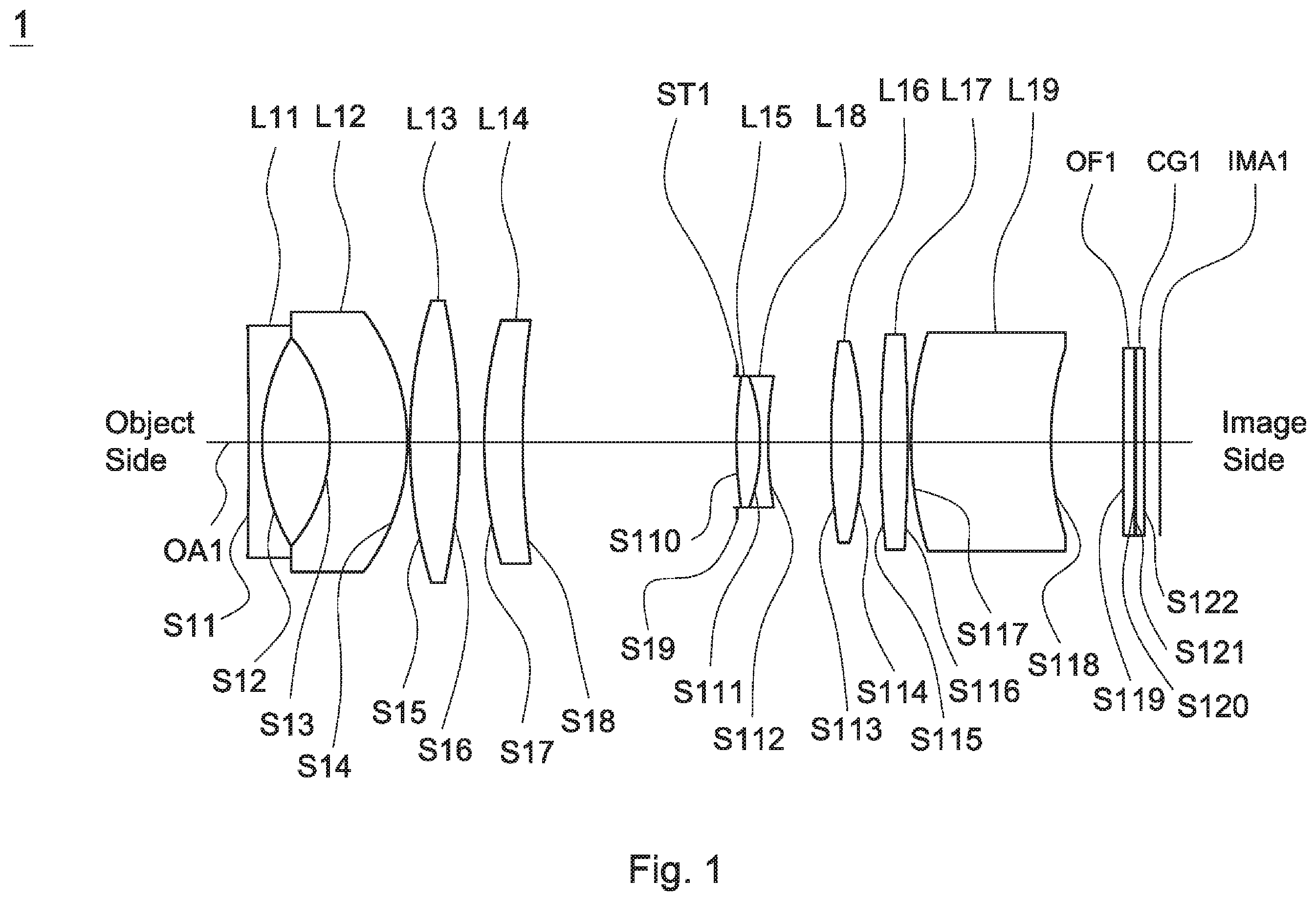
A detailed description of a wide-angle lens assembly in accordance with a first embodiment of the invention is as follows. Referring to , the wide-angle lens assembly 1 includes a first lens L 11 , a second lens L 12 , a third lens L 13 , a fourth lens L 14 , a stop ST 1 , a fifth lens L 15 , an eighth lens L 18 , a sixth lens L 16 , a seventh lens L 17 , a ninth lens L 19 , an optical filter OF 1 , and a cover glass CG 1 , all of which are arranged in order from an object side to an image side along an optical axis OA 1 . In operation, an image of light rays from the object side is formed at an image plane IMA 1 .
According to the foregoing, wherein: the first lens L 11 is a biconcave lens, wherein the object side surface S 11 is a concave surface; the object side surface S 13 of the second lens L 12 is a concave surface and the image side surface S 14 of the second lens L 12 is a convex surface; the third lens L 13 is a biconvex lens with positive refractive power and made of glass material, wherein the object side surface S 15 is a convex surface and the image side surface S 16 is a convex surface; the fourth lens L 14 is a meniscus lens, wherein the image side surface S 18 is a concave surface; the seventh lens L 17 is a biconvex lens, wherein the image side surface S 116 is a convex surface and the object side surface S 115 and the image side surface S 116 are spherical surfaces; the object side surface S 17 of the ninth lens L 19 is a convex surface and the image side surface S 18 of the ninth lens L 19 is a concave surface; both of the object side surface S 119 and image side surface S 120 of the optical filter OF 1 are plane surfaces; and both of the object side surface S 121 and image side surface S 122 of the cover glass CG 1 are plane surfaces.
With the above design of the lenses and stop ST 1 and at least any one of the conditions (1)-(4) satisfied, the wide-angle lens assembly 1 can have an effective decreased F-number, an effective increased resolution, and an effective resisted environmental temperature change.
If the value f/TTL of condition (1) is less than 0.2, it is difficult to achieve the purpose of miniaturization. Therefore, the value of f/TTL must be at least greater than 0.2. An optimal range for f/TTL is between 0.2 and 0.35. The wide-angle lens assembly has the best condition of miniaturization when satisfies the condition (1): 0.2<f/TTL<0.35.
Table 1 shows the optical specification of the wide-angle lens assembly 1 in .
TABLE 1
Effective Focal Length = 11.46 mm F-number = 1.83
Total Lens Length = 50.441 mm Field of View = 52.77 degrees
Radius of Thick- Effective
Surface Curvature ness Focal Length
Number (mm) (mm) Nd Vd (mm) Remark
S11 −312.446 0.806 1.92 24 −12.0725 The First
Lens L11
S12 11.545 3.746
S13 −9.094 4.242 1.62 63.4 −158.009 The Second
Lens L12
S14 −11.815 0.100
S15 26.077 2.793 1.77 49.6 19.939 The Third
Lens L13
S16 −35.869 1.350
S17 23.577 2.097 1.95 18 52.8144 The Fourth
Lens L14
S18 42.720 11.922
S19 ∞ −0.081 Stop ST1
S110 28.690 1.407 1.55 75.5 12.691 The Fifth
Lens L15
S111 −9.070 0.410 1.85 23.8 −7.5215 The Eighth
Lens L18
S112 21.812 3.486
S113 40.917 1.684 1.73 54.7 19.8258 The Sixth
Lens L16
S114 −21.965 0.983
S115 58.819 1.519 1.91 35.3 38.6457 The Seventh
Lens L17
S116 −86.562 0.135
S117 19.623 7.783 1.59 68.6 −3495.73 The Ninth
Lens L19
S118 16.569 3.971
S119 ∞ 0.550 1.52 64.2 Optical
Filter OF1
S120 ∞ 0.146
S121 ∞ 0.500 1.52 64.2 Cover Glass
CG1
S122 ∞ 0.893
Table 2 shows the parameters and condition values for conditions (1)-(4) in accordance with the first embodiment of the invention. It can be seen from Table 2 that the wide-angle lens assembly 1 of the first embodiment satisfies the conditions (1)-(4).
TABLE 2
A 7.375 mm IH 5.175 mm f 1234 21.7225 mm
f/TTL 0.23 T RL1 /T 1 9.66 f 1234 /f 1.90
A/IH 1.43
By the above arrangements of the lenses and stop ST 1 , the wide-angle lens assembly 1 of the first embodiment can meet the requirements of optical performance as seen in A- 2 C .
It can be seen from A that the field curvature of tangential direction and sagittal direction in the wide-angle lens assembly 1 of the first embodiment ranges from −0.015 mm to 0.02 mm. It can be seen from B that the distortion in the wide-angle lens assembly 1 of the first embodiment ranges from −9% to 0%. It can be seen from C that the lateral color in the wide-angle lens assembly 1 of the first embodiment ranges from −0.1 μm to 1.5 μm.
It is obvious that the field curvature, the distortion, and the lateral color of the wide-angle lens assembly 1 of the first embodiment can be corrected effectively. Therefore, the wide-angle lens assembly 1 of the first embodiment is capable of good optical performance.
Referring to , the wide-angle lens assembly 2 includes a first lens L 21 , a second lens L 22 , a third lens L 23 , a fourth lens L 24 , a stop ST 2 , a fifth lens L 25 , an eighth lens L 28 , a sixth lens L 26 , a ninth lens L 29 , a seventh lens L 27 , an optical filter OF 2 , and a cover glass CG 2 , all of which are arranged in order from an object side to an image side along an optical axis OA 2 . In operation, an image of light rays from the object side is formed at an image plane IMA 2 .
According to the foregoing, wherein: the first lens L 21 is a biconcave lens, wherein the object side surface S 21 is a concave surface; the object side surface S 23 of the second lens L 22 is a concave surface and the image side surface S 24 of the second lens L 22 is a convex surface; the third lens L 23 is a biconvex lens with positive refractive power and made of glass material, wherein the object side surface S 25 is a convex surface and the image side surface S 26 is a convex surface; the fourth lens L 24 is a meniscus lens, wherein the image side surface 28 is a concave surface; the object side surface S 215 of the ninth lens L 29 is a convex surface and the image side surface S 216 of the ninth lens L 29 is a concave surface; the seventh lens L 27 is a meniscus lens, wherein the image side surface S 218 is a concave surface and the object side surface S 217 and the image side surface S 218 are aspheric surfaces; both of the object side surface S 219 and image side surface S 220 of the optical filter OF 2 are plane surfaces; and both of the object side surface S 221 and image side surface S 222 of the cover glass CG 2 are plane surfaces.
With the above design of the lenses and stop ST 2 and at least any one of the conditions (1)-(4) satisfied, the wide-angle lens assembly 2 can have an effective decreased F-number, an effective increased resolution, and an effective resisted environmental temperature change.
If the value f 123 /f of condition (3) is less than 1, it will result in poor performance and low resolution for the wide-angle lens assembly. Therefore, the value of f 123 /f must be at least greater than 1. An optimal range of f 123 /f in condition (3) is between 1 and 2.1. The performance and resolution of the wide-angle lens assembly can be improved when satisfies the condition (3): 1<f 1234 /f<2.1.
Table 3 shows the optical specification of the wide-angle lens assembly 2 in .
TABLE 3
Effective Focal Length = 11.43 mm F-number = 1.80
Total Lens Length = 50.38 mm Field of View = 52.85 degrees
Radius of Thick- Effective
Surface Curvature ness Focal Length
Number (ram) (mm) Nd Vd (mm) Remark
S21 −195.162 0.806 1.92 24 −12.1269 The First
Lens L21
S22 11.872 4.939
S23 −10.399 4.413 1.62 63.4 −148.843 The Second
Lens L22
S24 −13.625 0.123
S25 31.430 3.511 1.77 49.6 22.0414 The Third
Lens L23
S26 −35.343 0.117
S27 22.335 2.781 1.95 18 52.0916 The Fourth
Lens L24
S28 38.382 6.910
S29 ∞ 1.815 Stop ST2
S210 16.402 5.318 1.55 75.5 12.656 The Fifth
Lens L25
S211 −10.711 0.410 1.85 23.8 −7.0313 The Eighth
Lens L28
S212 13.633 1.403
S213 15.594 2.689 1.7 55.5 12.514 The Sixth
Lens L26
S214 −18.379 0.134
S215 17.470 1.398 1.73 54.7 −54.949 The Ninth
Lens L29
S216 11.755 0.862
S217 21.574 6.680 1.81 25.5 64.1111 The Seventh
Lens L27
S218 31.947 0.971
S219 ∞ 0.550 1.52 64.2 Optical
Filter OF2
S220 ∞ 0.146
S221 ∞ 0.500 1.52 64.2 Cover Glass
CG2
S222 ∞ 0.893
The aspheric surface sag z of each aspheric lens in table 3 can be calculated by the following formula: z=ch 2 /{1+[1−( k+ 1) c 2 h 2 ] 1/2 }+Ah 4 +Bh 6 +Ch 8 +Dh 10 where cis curvature, his the vertical distance from the lens surface to the optical axis, k is conic constant and A, B, C, and Dare aspheric coefficients.
In the second embodiment, the conic constant k and the aspheric coefficients A, B, C, D of each aspheric lens are shown in Table 4.
TABLE 4
Surface
Number k A B C D
S217 −8.41418025 −7.3915E−05 −1.27118E−06 −4.03905E−08 0
S218 −12.0966342 −0.00014424 −2.776E−06 1.45412E−08 0
Table 5 shows the parameters and condition values for conditions (1)-(4) in accordance with the second embodiment of the invention. It can be seen from Table 5 that the wide-angle lens assembly 2 of the second embodiment satisfies the conditions (1)-(4).
TABLE 5
A 9.962 mm IH 5.175 mm f 1234 22.5744 mm
f/TTL 0.23 T RL1 /T 1 8.29 f 1234 /f 1.98
A/IH 1.93
By the above arrangements of the lenses and stop ST 2 , the wide-angle lens assembly 2 of the second embodiment can meet the requirements of optical performance as seen in A- 4 C .
It can be seen from A that the field curvature of tangential direction and sagittal direction in the wide-angle lens assembly 2 of the second embodiment ranges from −0.01 mm to 0.03 mm. It can be seen from B that the distortion in the wide-angle lens assembly 2 of the second embodiment ranges from −9% to 0%. It can be seen from C that the lateral color in the wide-angle lens assembly 2 of the second embodiment ranges from −0.5 μm to 1.1 μm.
It is obvious that the field curvature, the distortion, and the lateral color of the wide-angle lens assembly 2 of the second embodiment can be corrected effectively. Therefore, the wide-angle lens assembly 2 of the second embodiment is capable of good optical performance.
Referring to , the wide-angle lens assembly 3 includes a first lens L 31 , a second lens L 32 , a third lens L 33 , a fourth lens L 34 , a stop ST 3 , a fifth lens L 35 , an eighth lens L 38 , a ninth lens L 39 , a tenth lens L 310 , a sixth lens L 36 , a seventh lens L 37 , an optical filter OF 3 , and a cover glass CG 3 , all of which are arranged in order from an object side to an image side along an optical axis OA 3 . In operation, an image of light rays from the object side is formed at an image plane IMA 3 .
According to the foregoing, wherein: the first lens L 31 is a biconcave lens, wherein the object side surface S 31 is a concave surface; the object side surface S 33 of the second lens L 32 is a concave surface and the image side surface S 34 of the second lens L 32 is a convex surface; the third lens L 33 is a biconvex lens with positive refractive power and made of glass material, wherein the object side surface S 35 is a convex surface and the image side surface S 36 is a convex surface; the fourth lens L 34 is a meniscus lens, wherein the image side surface S 38 is a concave surface; the object side surface S 313 of the ninth lens L 39 is a convex surface and the image side surface S 314 of the ninth lens L 39 is a concave surface; the tenth lens L 310 is a meniscus lens with positive refractive power and made of glass material, wherein the object side surface S 314 is a convex surface, the image side surface S 315 is a concave surface, and the object side surface S 314 and the image side surface S 315 are spherical surfaces; the seventh lens L 37 is a meniscus lens, wherein the image side surface S 319 is a concave surface and the object side surface S 318 and the image side surface S 319 are aspheric surfaces; the tenth lens L 310 and the ninth lens L 39 are cemented; both of the object side surface S 320 and image side surface S 321 of the optical filter OF 3 are plane surfaces; and both of the object side surface S 322 and image side surface S 323 of the cover glass CG 3 are plane surfaces.
With the above design of the lenses and stop ST 3 and at least any one of the conditions (1)-(4) satisfied, the wide-angle lens assembly 3 can have an effective decreased F-number, an effective increased resolution, and an effective resisted environmental temperature change.
Table 6 shows the optical specification of the wide-angle lens assembly 3 in .
TABLE 6
Effective Focal Length = 11.44 mm F-number = 1.85
Total Lens Length = 50.28 mm Field of View = 52.846 degrees
Radius of Thick- Effective
Surface Curvature ness Focal Length
Number (mm) (mm) Nd Vd (mm) Remark
S31 −62.751 0.410 1.92 23.9 −11.9307 The First
Lens L31
S32 13.363 3.347
S33 −12.161 7.171 1.62 64.3 −880.849 The Second
Lens L32
S34 −15.245 0.100
S35 28.316 4.302 1.77 49.7 20.1521 The Third
Lens L33
S36 −32.287 0.433
S37 18.549 5.139 1.95 18 40.5759 The Fourth
Lens L34
S38 31.067 2.250
S39 ∞ −0.158 Stop ST3
S310 12.741 4.260 1.55 75.5 13.8049 The Fifth
Lens L35
S311 −16.582 0.505 1.85 23.8 −6.9495 The Eighth
Lens L38
S312 9.246 2.311
S313 106.080 0.450 1.81 25.4 −10.264 The Ninth
Lens L39
S314 7.652 2.239 1.83 42.7 12.3768 The Tenth
Lens L310
S315 25.574 1.298
S316 125.763 1.741 1.59 68.6 25.3781 The Sixth
Lens L36
S317 −17.000 4.580
S318 11.217 5.557 1.77 49.6 16.7102 The Seventh
Lens L37
S319 67.132 1.312
S320 ∞ 0.550 1.52 64.2 Optical
Filter OF3
S321 ∞ 0.146
S322 ∞ 0.500 1.52 64.2 Cover Glass
CG3
S323 ∞ 0.893
The definition of aspheric surface sag z of each aspheric lens in table 6 is the same as that of in Table 3, and is not described here again.
In the third embodiment, the conic constant k and the aspheric coefficients A, B, C, D of each aspheric surface are shown in Table 7.
TABLE 7
Surface
Number k A B C D
S318 0.008483281 −2.84479E−06 4.4325E−08 −1.02505E−10 6.29549E−12
S319 5.000882367 −4.72369E−07 −5.8135E−07 2.44779E−09 3.64253E−11
Table 8 shows the parameters and condition values for conditions (1)-(4) in accordance with the third embodiment of the invention. It can be seen from Table 8 that the wide-angle lens assembly 3 of the third embodiment satisfies the conditions (1)-(4).
TABLE 8
A 9.197 mm IH 5.175 mm f 1234 12.1991 mm
f/TTL 0.23 T RL1 /T 1 13.55 f 1234 /f 1.07
A/IH 1.78
By the above arrangements of the lenses and stop ST 3 , the wide-angle lens assembly 3 of the third embodiment can meet the requirements of optical performance as seen in A- 6 C .
It can be seen from A that the field curvature of tangential direction and sagittal direction in the wide-angle lens assembly 3 of the third embodiment ranges from −0.015 mm to 0.025 mm. It can be seen from B that the distortion in the wide-angle lens assembly 3 of the third embodiment ranges from −9% to 0%. It can be seen from C that the lateral color in the wide-angle lens assembly 3 of the third embodiment ranges from 0 μm to 2.2 μm.
It is obvious that the field curvature, the distortion, and the lateral color of the wide-angle lens assembly 3 of the third embodiment can be corrected effectively. Therefore, the wide-angle lens assembly 3 of the third embodiment is capable of good optical performance.
Referring to , the wide-angle lens assembly 4 includes a first lens L 41 , a second lens L 42 , a third lens L 43 , a fourth lens L 44 , a fifth lens L 45 , a stop ST 4 , a tenth lens L 410 , an eighth lens L 48 , a sixth lens L 46 , a ninth lens L 49 , a seventh lens L 47 , an optical filter OF 4 , and a cover glass CG 4 , all of which are arranged in order from an object side to an image side along an optical axis OA 4 . In operation, an image of light rays from the object side is formed at an image plane IMA 4 .
According to the foregoing, wherein: the first lens L 41 is a meniscus lens, wherein the object side surface S 41 is a convex surface; the object side surface S 43 of the second lens L 42 is a convex surface and the image side surface S 44 of the second lens L 42 is a concave surface; the third lens L 43 is a biconcave lens with negative refractive power and made of glass material, wherein the object side surface S 45 is a concave surface and the image side surface S 46 is a concave surface; the fourth lens L 44 is a biconvex lens, wherein the image side surface 48 is a convex surface; the tenth lens L 410 is a biconvex lens with positive refractive power and made of glass material, wherein the object side surface S 412 is a convex surface, the image side surface S 413 is a convex surface, and the object side surface S 412 and the image side surface S 413 are spherical surfaces; the object side surface S 416 of the ninth lens L 49 is a concave surface and the image side surface S 417 of the ninth lens L 49 is a convex surface; the seventh lens L 47 is a biconvex lens, wherein the image side surface S 419 is a convex surface and the object side surface S 418 and the image side surface S 419 are spherical surfaces; the ninth lens L 49 and the sixth lens L 46 are cemented; both of the object side surface S 420 and image side surface S 421 of the optical filter OF 4 are plane surfaces; and both of the object side surface S 422 and image side surface S 423 of the cover glass CG 4 are plane surfaces.
With the above design of the lenses and stop ST 4 and at least any one of the conditions (5)-(12) satisfied, the wide-angle lens assembly 4 can have an effective shortened total lens length, an effective increased field of view, an effective increased brightness, an effective increased resolution, an effective resisted environmental temperature change, an effective increased resolution, an effective corrected aberration, and is capable of an effective corrected chromatic aberration.
Table 9 shows the optical specification of the wide-angle lens assembly 4 in .
TABLE 9
Effective Focal Length = 1.245 mm F-number = 1.6
Total Lens Length = 26.118 mm Field of View = 181.500 degrees
Radius of Thick- Effective
Surface Curvature ness Focal Length
Number (ram) (mm) Nd Vd (mm) Remark
S41 15.000 0.900 1.835 42.7 −13.2954 The First
Lens L41
S42 5.421 2.647
S43 15.235 0.600 1.883 40.8 −5.3536 The Second
Lens L42
S44 3.553 4.606
S45 −8.305 0.600 1.487 70.2 −6.0388 The Third
Lens L43
S46 4.081 0.953
S47 12.000 1.668 1.847 23.8 6.8083 The Fourth
Lens L44
S48 −15.000 3.182
S49 20.000 1.139 1.741 52.6 10.7961 The Fifth
Lens L45
S410 −8.131 0.367
S411 ∞ −0.269 Stop ST4
S412 4.315 1.991 1.497 81.5 4.6915 The Tenth
Lens L410
S413 −4.315 0.500 1.847 23.8 −2.7988 The Eighth
Lens L48
S414 5.629 0.141
S415 9.615 1.731 1.497 81.5 5.6354 The Sixth
Lens L46
S416 −3.727 0.500 1.835 42.7 −25.8055 The Ninth
Lens L49
S417 −10.000 0.100
S418 7.484 1.259 1.835 42.7 8.2361 The Seventh
Lens L47
S419 −20.000 0.887
S420 ∞ 0.210 1.517 64.2 Optical
Filter OF4
S421 ∞ 1.806
S422 ∞ 0.400 1.517 64.2 Cover Glass
CG4
S423 ∞ 0.200
Table 10 shows the parameters and condition values for conditions (5)(12) in accordance with the fourth embodiment of the invention. It can be seen from Table 10 that the wide-angle lens assembly 4 of the fourth embodiment satisfies the conditions (5)-(12).
TABLE 10
IH 1.875 mm A 3.342 mm IH 1.875 mm
f/IH 0.664 R 21 − R 22 11.682 mm R 31 /R 32 −2.035
(f 3 + f RL1 )/f 1.765 Vd 5 /Nd 5 30.213 | f 1 /f | 10.679
R RL21 + R RL22 −13.727 mm A/IH 1.78
By the above arrangements of the lenses and stop ST 4 , the wide-angle lens assembly 4 of the fourth embodiment can meet the requirements of optical performance as seen in A- 8 C .
It can be seen from A that the distortion in the wide-angle lens assembly 4 of the fourth embodiment ranges from −5% to 0%. It can be seen from B that the through focus modulation transfer function in the lens assembly 4 of the fourth embodiment ranges from 0 to 0.75 as focus shift ranges from −0.05 mm to 0.05 mm when temperature is equal to −20° C., 40° C., 80° C. respectively. It can be seen from C that the modulation transfer function in the lens assembly 4 of the fourth embodiment ranges from 0.0 to 0.74 as focus shift ranges from −0.05 mm to 0.05 mm when wavelength band is red-green-blue light, infrared light respectively.
It is obvious that the distortion of the wide-angle lens assembly 4 of the fourth embodiment can be corrected effectively, and the depth of focus of high temperature, low temperature, visible light, and infrared light for the lens assembly 4 of the fourth embodiment can meet the requirement. Therefore, the wide-angle lens assembly 4 of the fourth embodiment is capable of good optical performance.
Referring to , the wide-angle lens assembly 5 includes a first lens L 51 , a second lens L 52 , a third lens L 53 , a fourth lens L 54 , a fifth lens L 55 , a stop ST 5 , a sixth lens L 56 , an eighth lens L 58 , a seventh lens L 57 , a ninth lens L 59 , a tenth lens L 510 , an optical filter OF 5 , and a cover glass CG 5 , all of which are arranged in order from an object side to an image side along an optical axis OA 5 . In operation, an image of light rays from the object side is formed at an image plane IMA 5 .
According to the foregoing, wherein: the first lens L 51 is a meniscus lens, wherein the object side surface S 51 is a convex surface; the object side surface S 53 of the second lens L 52 is a convex surface and the image side surface S 54 of the second lens L 52 is a concave surface; the third lens L 53 is a biconcave lens with negative refractive power and made of glass material, wherein the object side surface S 55 is a concave surface and the image side surface S 56 is a concave surface; the fourth lens L 54 is a biconvex lens, wherein the image side surface S 58 is a convex surface; the seventh lens L 57 is a biconvex lens, wherein the image side surface S 516 is a convex surface and the object side surface S 515 and the image side surface S 516 are spherical surfaces; the object side surface S 516 of the ninth lens L 59 is a concave surface and the image side surface S 517 of the ninth lens L 59 is a convex surface; the tenth lens L 510 is a biconvex lens with positive refractive power and made of glass material, wherein the object side surface S 518 is a convex surface, the image side surface S 519 is a convex surface, and the object side surface S 518 and the image side surface S 519 are spherical surfaces; the ninth lens L 59 and the seventh Lens L 57 are cemented; both of the object side surface S 520 and image side surface S 521 of the optical filter OF 5 are plane surfaces; and both of the object side surface S 522 and image side surface S 523 of the cover glass CG 5 are plane surfaces.
With the above design of the lenses and stop ST 5 and at least any one of the conditions (5)-(12) satisfied, the wide-angle lens assembly 5 can have an effective shortened total lens length, an effective increased field of view, an effective increased brightness, an effective increased resolution, an effective resisted environmental temperature change, an effective increased resolution, an effective corrected aberration, and is capable of an effective corrected chromatic aberration.
Table 11 shows the optical specification of the wide-angle lens assembly 5 in .
TABLE 11
Effective Focal Length = 1.210 mm F-number = 1.6
Total Lens Length = 25.291 mm Field of View = 182.800 degrees
Radius of Thick- Effective
Surface Curvature ness Focal Length
Number (mm) (mm) Nd Vd (mm) Remark
S51 11.442 0.900 1.946 18.0 −11.5770 The First
Lens L51
S52 5.063 2.653
S53 15.286 0.600 1.743 49.3 −6.3095 The Second
Lens L52
S54 4.021 3.000
S55 −5.000 0.600 1.834 37.2 −5.5656 The Third
Lens L53
S56 6.000 1.986
S57 12.000 1.759 1.805 25.4 7.1917 The Fourth
Lens L54
S58 −13.000 2.478
S59 17.448 2.190 1.847 23.8 9.8235 The Fifth
Lens L55
S510 −11.573 0.367
S511 ∞ −0.269 Stop ST5
S512 3.803 1.518 1.497 81.5 4.0887 The Sixth
Lens L56
S513 −3.803 0.500 1.847 23.8 −2.3417 The Eighth
Lens L58
S514 4.463 0.320
S515 54.712 1.318 1.497 81.5 5.7034 The Seventh
Lens L57
S516 −2.973 0.500 1.835 42.7 −22.6959 The Ninth
Lens L59
S517 −3.793 0.100
S518 8.360 1.273 1.595 67.7 6.4330 The Tenth
Lens L510
S519 −14.142 0.487
S520 ∞ 0.210 1.517 64.2 Optical
Filter OF5
S521 ∞ 2.202
S522 ∞ 0.400 1.517 64.2 Cover Glass
CG5
S523 ∞ 0.200
Table 12 shows the parameters and condition values for conditions (5)-(12) in accordance with the fifth embodiment of the invention. It can be seen from Table 12 that the wide-angle lens assembly 5 of the fifth embodiment satisfies the conditions (5)-(12).
TABLE 12
IH 1.875 mm A 3.152 mm IH 1.875 mm
f/IH 0.645 R 21 − R 22 11.265 mm R 31 /R 32 −0.833
(f 3 + f RL1 )/f 0.717 Vd 5 /Nd 5 12.886 | f 1 /f | 9.568
R RL21 + R RL22 −6.766 mm A/IH 1.68
By the above arrangements of the lenses and stop ST 5 , the wide-angle lens assembly 5 of the fifth embodiment can meet the requirements of optical performance as seen in A- 10 C .
It can be seen from A that the distortion in the wide-angle lens assembly 5 of the fifth embodiment ranges from −3% to 0%. It can be seen from B that the through focus modulation transfer function in the lens assembly 5 of the fifth embodiment ranges from 0 to 0.72 as focus shift ranges from −0.05 mm to 0.05 mm when temperature is equal to −20° C., 40° C., 80° C. respectively. It can be seen from C that the modulation transfer function in the lens assembly 5 of the fifth embodiment ranges from 0.0 to 0.72 as focus shift ranges from −0.05 mm to 0.05 mm when wavelength band is red-green-blue light, infrared light respectively.
It is obvious that the distortion of the wide-angle lens assembly 5 of the fifth embodiment can be corrected effectively, and the depth of focus of high temperature, low temperature, visible light, and infrared light for the lens assembly 5 of the fifth embodiment can meet the requirement. Therefore, the wide-angle lens assembly 5 of the fifth embodiment is capable of good optical performance.
Referring to , the wide-angle lens assembly 6 includes a first lens L 61 , a second lens L 62 , a third lens L 63 , a fourth lens L 64 , a fifth lens L 65 , a stop ST 6 , a tenth lens L 610 , an eighth lens L 68 , a sixth lens L 66 , a ninth lens L 69 , a seventh lens L 67 , an optical filter OF 6 , and a cover glass CG 6 , all of which are arranged in order from an object side to an image side along an optical axis OA 6 . In operation, an image of light rays from the object side is formed at an image plane IMA 6 .
According to the foregoing, wherein: the first lens L 61 is a meniscus lens, wherein the object side surface S 61 is a convex surface; the object side surface S 63 of the second lens L 62 is a convex surface and the image side surface S 64 of the second lens L 62 is a concave surface; the third lens L 63 is a biconcave lens with negative refractive power and made of glass material, wherein the object side surface S 65 is a concave surface and the image side surface S 66 is a concave surface; the fourth lens L 64 is a biconvex lens, wherein the image side surface S 68 is a convex surface; the tenth lens L 610 is a biconvex lens with positive refractive power and made of glass material, wherein the object side surface S 612 is a convex surface, the image side surface S 613 is a convex surface, and the object side surface S 612 and the image side surface S 613 are spherical surfaces; the object side surface S 616 of the ninth lens L 69 is a concave surface and the image side surface S 617 of the ninth lens L 69 is a convex surface; the seventh lens L 67 is a biconvex lens, wherein the image side surface S 619 is a convex surface and the object side surface S 618 and the image side surface S 619 are spherical surfaces; the ninth lens L 69 and the sixth lens L 66 are cemented; both of the object side surface S 620 and image side surface S 621 of the optical filter OF 6 are plane surfaces; and both of the object side surface S 622 and image side surface S 623 of the cover glass CG 6 are plane surfaces.
With the above design of the lenses and stop ST 6 and at least any one of the conditions (5)-(12) satisfied, the wide-angle lens assembly 6 can have an effective shortened total lens length, an effective increased field of view, an effective increased brightness, an effective increased resolution, an effective resisted environmental temperature change, an effective increased resolution, an effective corrected aberration, and is capable of an effective corrected chromatic aberration.
Table 13 shows the optical specification of the wide-angle lens assembly 6 in .
TABLE 13
Effective Focal Length = 1.330 mm F-number = 1.7
Total Lens Length = 26.015 mm Field of View = 180.000 degrees
Radius of Thick- Effective
Surface Curvature ness Focal Length
Number (mm) (mm) Nd Vd (mm) Remark
S61 15.119 0.898 1.883 40.8 −10.0926 The First
Lens L61
S62 5.278 2.235
S63 9.309 0.686 1.883 40.8 −7.1092 The Second
Lens L62
S64 3.629 3.744
S65 −4.455 0.600 1.497 81.6 −5.7507 The Third
Lens L63
S66 7.953 0.736
S67 23.137 1.962 1.954 32.3 6.9875 The Fourth
Lens L64
S68 −7.716 3.936
S69 26.772 1.290 1.497 81.6 12.2340 The Fifth
Lens L65
S610 −13.496 0.372
S611 ∞ −0.281 Stop ST6
S612 3.815 1.526 1.497 81.6 6.0807 The Tenth
Lens L610
S613 −12.741 0.501 1.847 23.8 −3.6541 The Eighth
Lens L68
S614 4.201 0.265
S615 7.409 1.995 1.497 81.6 4.6597 The Sixth
Lens L66
S616 −3.077 0.502 1.835 42.7 −8.9554 The Ninth
Lens L69
S617 −5.602 0.102
S618 6.927 1.248 1.835 42.7 6.9022 The Seventh
Lens L67
S619 −32.249 0.500
S620 ∞ 0.210 1.517 64.2 Optical
Filter OF6
S621 ∞ 2.387
S622 ∞ 0.400 1.517 64,2 Cover Glass
CG6
S623 ∞ 0.200
Table 14 shows the parameters and condition values for conditions (5)-(12) in accordance with the sixth embodiment of the invention. It can be seen from Table 14 that the wide-angle lens assembly 6 of the sixth embodiment satisfies the conditions (5)-(12).
TABLE 14
IH 1.875 mm A 3.172 mm IH 1.875 mm
f/IH 0.709 R 21 − R 22 5.680 mm R 31 /R 32 −0.560
(f 3 + f RL1 )/f 0.866 Vd 5 /Nd 5 54.509 | f 1 /f | 7.588
R RL21 + R RL22 −8.679 mm A/IH 1.69
By the above arrangements of the lenses and stop ST 6 , the wide-angle lens assembly 6 of the sixth embodiment can meet the requirements of optical performance as seen in A- 12 C .
It can be seen from A that the distortion in the wide-angle lens assembly 6 of the sixth embodiment ranges from −10% to 0%. It can be seen from B that the through focus modulation transfer function in the lens assembly 6 of the sixth embodiment ranges from 0 to 0.73 as focus shift ranges from −0.05 mm to 0.05 mm when temperature is equal to −20° C., 40° C., 80° C. respectively. It can be seen from C that the modulation transfer function in the lens assembly 6 of the sixth embodiment ranges from 0.0 to 0.73 as focus shift ranges from −0.05 mm to 0.05 mm when wavelength band is red-green-blue light, infrared light respectively.
It is obvious that the distortion of the wide-angle lens assembly 6 of the sixth embodiment can be corrected effectively, and the depth of focus of high temperature, low temperature, visible light, and infrared light for the lens assembly 6 of the sixth embodiment can meet the requirement. Therefore, the wide-angle lens assembly 6 of the sixth embodiment is capable of good optical performance.
While the invention has been described by way of example and in terms of the preferred embodiment(s), it is to be understood that the invention is not limited thereto. On the contrary, it is intended to cover various modifications and similar arrangements and procedures, and the scope of the appended claims therefore should be accorded the broadest interpretation so as to encompass all such modifications and similar arrangements and procedures.
Figures (20)
Citations
This patent cites (20)
- US8908292
- US9235036
- US20120262803
- US20170227746
- US205562935
- US106019532
- US107045185
- US107167903
- US107632369
- US107632379
- US207164349
- US108227155
- US108519660
- US108563000
- US109814236
- US208953767
- US201940121
- US2019090949
- US201007206
- USI671566