AC-AC Converter with Open Phase Detection Based on Second Harmonic
Abstract
A power conversion device of an embodiment includes a rectifier that full-wave rectifies alternating current of a plurality of phases supplied from a power supply side, a capacitor that smoothes an output voltage of the rectifier, a voltage detection unit that detects the smoothed voltage, and an open phase detection unit that detects that an open phase has occurred in the alternating current of the plurality of phases based on a component having a frequency that is twice as high as a fundamental frequency of the alternating current of the plurality of phases included in frequency components of the smoothed voltage.
Claims (11)
1. A power conversion device comprising: a rectifier that full-wave rectifies alternating current of a plurality of phases supplied from a power supply side; a capacitor that smoothes an output voltage of the rectifier; a voltage detection unit that detects the smoothed voltage; and an open phase detection unit that detects that an open phase has occurred in the alternating current of the plurality of phases based on a component having a frequency that is twice as high as a fundamental frequency of the alternating current of the plurality of phases included in frequency components of the smoothed voltage, wherein the open phase detection unit derives a frequency spectrum of the smoothed voltage by FFT processing, and when the voltage of the component having the frequency, which is twice as high as the fundamental frequency of the alternating current of the plurality of phases, is larger than a first threshold voltage V and is equal to or less than a second threshold voltage larger than the first threshold voltage in the derived frequency spectrum, the open phase detection unit determines that the open phase has occurred in a phase other than a phase to which the open phase detection unit is connected among the plurality of phases.
11. An open phase detection device comprising: a voltage detection unit that detects a voltage that is rectified by a rectifier, which full-wave rectifies alternating current of a plurality of phases supplied from a power supply side, and smoothed by a capacitor; and an open phase detection unit detects that an open phase has occurred in the alternating current of the plurality of phases based on a component having a frequency that is twice as high as a fundamental frequency of the alternating current of the plurality of phases included in frequency components of the smoothed voltage, wherein the open phase detection unit derives a frequency spectrum of the smoothed voltage by FFT processing, and when the voltage of the component having the frequency, which is twice as high as the fundamental frequency of the alternating current of the plurality of phases, is larger than a first threshold voltage V and is equal to or less than a second threshold voltage larger than the first threshold voltage in the derived frequency spectrum, the open phase detection unit determines that the open phase has occurred in a phase other than a phase to which the open phase detection unit is connected among the plurality of phases.
Show 9 dependent claims
2. The power conversion device according to claim 1 , wherein, when the component having the frequency, which is twice as high as the fundamental frequency of the alternating current of the plurality of phases, is detected as exceeding a predetermined magnitude among the frequency components of the smoothed voltage, the open phase detection unit detects that the open phase has occurred in the alternating current of the plurality of phases.
3. The power conversion device according to claim 1 , wherein the open phase detection unit extracts the component having the frequency that is twice as high as the fundamental frequency from the frequency spectrum.
4. The power conversion device according to claim 1 , wherein, when a voltage of the component having the frequency, which is twice as high as the fundamental frequency of the alternating current of the plurality of phases, is larger than a predetermined threshold voltage in the derived frequency spectrum, the open phase detection unit determines that the open phase has occurred in any one of the plurality of phases.
5. The power conversion device according to claim 1 , wherein, when the voltage of the component having the frequency, which is twice as high as the fundamental frequency of the alternating current of the plurality of phases, is larger than the second threshold voltage in the derived frequency spectrum, the open phase detection unit determines that the open phase has occurred in the phase to which the open phase detection unit is connected among the plurality of phases.
6. The power conversion device according to claim 1 , wherein, in a case where the fundamental frequency of the alternating current of the plurality of phases is substantially equal to a fundamental frequency of alternating current of a plurality of second phases generated by an inverter that receives supply of current rectified by the rectifier and smoothed by the capacitor, when the voltage of the component having the frequency, which is twice as high as the fundamental frequency of the alternating current of the plurality of phases, is larger than a third threshold voltage in the derived frequency spectrum, the open phase detection unit determines that the open phase has occurred in the phase to which the open phase detection unit is connected among the plurality of phases.
7. The power conversion device according to claim 1 , wherein the open phase detection unit comprises: a band pass filter that extracts a component having a frequency twice as high as the smoothed voltage.
8. The power conversion device according to claim 1 , further comprising: an inverter that generates AC power to be supplied to a load by using the smoothed voltage, wherein a magnitude of the component having the frequency, which is twice as high as the fundamental frequency of the alternating current of the plurality of phases, varies depending on power consumption of the load.
9. The power conversion device according to claim 1 , further comprising: an inverter that generates AC power to be supplied to a load by using the smoothed voltage, wherein, among ripples of the smoothed voltage, a ripple at a timing corresponding to a phase in which an open phase has occurred is larger than a ripple at a timing corresponding to another phase, and a magnitude of the component having the frequency, which is twice as high as the fundamental frequency of the alternating current of the plurality of phases, varies depending on power consumption of the load.
10. The power conversion device according to claim 1 , further comprising: an inverter that generates AC power to be supplied to a load by using the smoothed voltage, wherein a fundamental frequency of the AC power generated by the inverter is different from the fundamental frequency of the alternating current of the plurality of phases.
Full Description
Show full text →
TECHNICAL FIELD
Embodiments of the present invention relate to a power conversion device and an open phase detection device.
BACKGROUND ART
There has been known an open phase detection device that detects an open phase (broken phase) occurring on a secondary side of a transformer based on a voltage on an AC input side. It is desired to detect the open phase based on a voltage between terminals of a capacitor, which is detected by a voltage detector.
CITATION LIST
Patent Literature
[Patent Literature 1]
Japanese Unexamined Patent Application, First Publication No. 2010-187521
SUMMARY OF INVENTION
Technical Problem
An object of the present invention is to provide an open phase detection device capable of detecting an open phase based on a voltage between terminals of a capacitor, which is detected by a voltage detector.
Solution to Problem
A power conversion device according to the present invention includes a rectifier, a capacitor, a voltage detection unit, and an open phase detection unit. The rectifier full-wave rectifies alternating current of a plurality of phases supplied from a power supply side. The capacitor smoothes an output voltage of the rectifier. The voltage detection unit detects the smoothed voltage. The open phase detection unit detects that an open phase has occurred in the alternating current of the plurality of phases based on a component having a frequency that is twice as high as a fundamental frequency of the alternating current of the plurality of phases included in frequency components of the smoothed voltage.
BRIEF DESCRIPTION OF DRAWINGS
is a configuration diagram of a power conversion system of a first embodiment.
is a configuration diagram of an open phase detection device of the first embodiment.
A is a diagram for explaining an example of a voltage waveform of three-phase AC power supplied to a transformer from an AC power supply of the first embodiment.
B is a diagram for explaining an example of a pulsating current full-wave rectified by a rectifier when there is no open phase on transformer output lines.
C is a diagram for explaining an example of a pulsating current full-wave rectified by the rectifier when there is an open phase on the transformer output lines.
is a flowchart of an open phase determination process of the open phase detection device of the first embodiment.
is a configuration diagram of a power conversion system of a second embodiment.
A is a diagram illustrating a simulation result of an inter-terminal voltage by an open phase detection device of the second embodiment when there is no open phase.
B is a diagram illustrating a simulation result of a frequency spectrum by the open phase detection device of the second embodiment when there is no open phase.
C is a diagram illustrating a simulation result of an inter-terminal voltage by the open phase detection device of the second embodiment when there is an open phase.
D is a diagram illustrating a simulation result of a frequency spectrum by the open phase detection device of the second embodiment when there is an open phase.
A is a diagram illustrating a simulation result of a double power supply frequency component when an output frequency of an inverse conversion device group is 50 Hz and a power supply frequency is 25 Hz in the power conversion system of the second embodiment.
B is a diagram illustrating a simulation result of the double power supply frequency component when the output frequency of the inverse conversion device group is 50 Hz and the power supply frequency is 50 Hz in the power conversion system of the second embodiment.
C is a diagram illustrating a simulation result of the double power supply frequency component when the output frequency of the inverse conversion device group is 50 Hz and the power supply frequency is 60 Hz in the power conversion system of the second embodiment.
D is a diagram illustrating a simulation result of the double power supply frequency component when the output frequency of the inverse conversion device group is 50 Hz and the power supply frequency is 100 Hz in the power conversion system of the second embodiment.
E is a diagram illustrating a simulation result of the double power supply frequency component when the output frequency of the inverse conversion device group is 100 Hz and the power supply frequency is 50 Hz in the power conversion system of the second embodiment.
F is a diagram illustrating a simulation result of the double power supply frequency component when the output frequency of the inverse conversion device group is 200 Hz and the power supply frequency is 50 Hz in the power conversion system of the second embodiment.
is a diagram illustrating a simulation result of the double power supply frequency component when a current of an electric motor is changed in the power conversion system of the second embodiment.
is a flowchart of an open phase determination process of the open phase detection device of the second embodiment.
is a configuration diagram of a power conversion system of a third embodiment.
is a configuration diagram of an open phase detection device of a first modified example of the first to third embodiments.
is a configuration diagram of an open phase detection device of a second modified example of the first to third embodiments.
DESCRIPTION OF EMBODIMENTS
Hereinafter, an open phase detection device and an open phase detection method of a power conversion device of embodiments will be described with reference to the drawings. In the following description, elements having the same or similar functions are denoted by the same reference numerals.
The term “connection” in the specification is not limited to a case where connection is made physically and also includes a case where connection is made electrically.
In the present specification, an open phase means that power of a phase is not supplied due to disconnection of windings of electric wires or a transformer, connection failure, melting of a fuse, open circuit, and the like.
In the present specification, a frequency of a fundamental wave in the waveform of three-phase AC power is referred to as a fundamental frequency.
First Embodiment
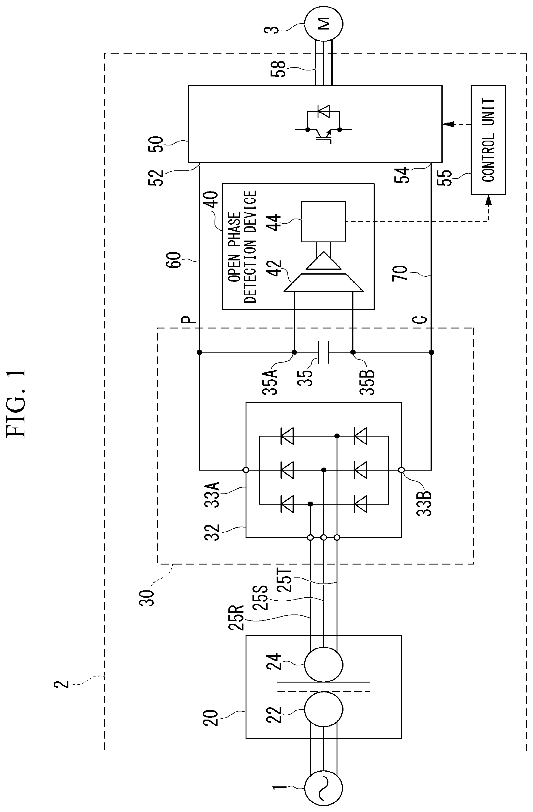
is a configuration diagram of a power conversion system 2 of a first embodiment. illustrates an AC power supply 1 , the power conversion system 2 , and an electric motor 3 .
The AC power supply 1 is a commercial power supply, a power generator and the like, and supplies three-phase AC power to the power conversion system 2 .
The electric motor 3 is, for example, an AC variable speed electric motor such as an induction motor. The electric motor 3 is driven by AC power supplied from the power conversion system 2 and outputs rotational driving force to an output shaft (not illustrated).
The power conversion system 2 includes, for example, a transformer 20 , a rectifier 32 , a capacitor 35 , an open phase detection device 40 , an inverse conversion device 50 , and a control unit 55 . The power conversion system 2 forward-converts the three-phase AC power, which is supplied from the AC power supply 1 , by using the rectifier 32 and the capacitor 35 to generate DC power, inversely converts the DC power by using the inverse conversion device 50 to generate three-phase AC power, and supplies the three-phase AC power to the electric motor 3 .
The transformer 20 is, for example, a three-phase transformer. The transformer 20 includes, for example, a primary winding 22 and a secondary winding 24 . The transformer 20 receives the supply of the three-phase AC power from the AC power supply 1 through the primary winding 22 , transforms the received three-phase AC power, and outputs the transformed three-phase AC power from the secondary winding 24 . One end of each of transformer output lines 25 R, 25 S, and 25 T is connected to each of the R, S, and T phases of the secondary winding 24 . The other ends of the transformer output lines 25 R, 25 S, and 25 T are connected to AC input terminals of the rectifier 32 . The three-phase AC power output from the secondary winding 24 is output to the rectifier 32 via the transformer output lines 25 R, 25 S, and 25 T. The secondary winding 24 and the transformer output lines 25 R, 25 S, and 25 T are a part of an object whose open phase is detected by the open phase detection device 40 .
The rectifier 32 includes, for example, an AC input terminal, a three-phase full-bridge diode rectifier circuit, a rectifier positive electrode terminal 33 A, and a rectifier negative electrode terminal 33 B. The rectifier 32 full-wave rectifies the three-phase AC power, which is supplied to the AC input terminal of the rectifier 32 from the transformer 20 , by the three-phase full-bridge diode rectifier circuit, and outputs the rectified DC power from the rectifier positive electrode terminal 33 A and the rectifier negative electrode terminal 33 B.
The rectifier positive electrode terminal 33 A is connected to one end of a positive electrode line 60 . The other end of the positive electrode line 60 is connected to a positive electrode input terminal 52 of the inverse conversion device 50 . The rectifier negative electrode terminal 33 B is connected to one end of a negative electrode line 70 . The other end of the negative electrode line 70 is connected to a negative electrode input terminal 54 of the inverse conversion device 50 .
The capacitor 35 is connected between the positive electrode line 60 and the negative electrode line 70 and smoothes the DC power that is output from the rectifier 32 . For example, the rectifier 32 and the capacitor 35 form a forward conversion device 30 . The forward conversion device 30 is an example of a power conversion device.
The open phase detection device 40 includes, for example, a voltage detector 42 and an open phase detection unit 44 .
The voltage detector 42 , for example, detects a voltage applied between a positive electrode terminal 35 A and a negative electrode terminal 35 B of the capacitor 35 (hereinafter, referred to an inter-terminal voltage), and outputs a detection value representing the inter-terminal voltage to the open phase detection unit 44 . The voltage detector 42 , for example, detects the inter-terminal voltage via a DC voltage converter and the like whose input and output are insulated, quantizes the inter-terminal voltage by an analog-to-digital (AD) converter (not illustrated), and outputs the quantized voltage as a voltage detection value representing the inter-terminal voltage. The voltage detector 42 is an example of a voltage detection unit.
The open phase detection unit 44 acquires the voltage detection value representing the inter-terminal voltage from the voltage detector 42 and determines, based on the acquired voltage detection value, whether an open phase has occurred in an open phase detection target range. The open phase detection unit 44 and the open phase detection target range detected by the open phase detection unit 44 will be described below.
The inverse conversion device 50 is, for example, a two-level inverter including a switching element such as an insulated gate bipolar transistor (IGBT). The switching element of the inverse conversion device 50 is pulse width modulation (PWM)-controlled by the control unit 55 . The inverse conversion device 50 converts the DC power, which is supplied from the rectifier 32 via the positive electrode line 60 and the negative electrode line 70 , into three-phase AC power having a variable frequency and a variable voltage. The inverse conversion device 50 supplies the converted three-phase AC power to the electric motor 3 via a load power line 58 .
The control unit 55 outputs a gate pulse signal to the switching element of the inverse conversion device 50 by feedback control based on a detection value and the like of a current detector (not illustrated) that detects a load current flowing through the load power line 58 , thereby PWM-controlling the switching element. Moreover, the control unit 55 receives an open phase detection signal that is output in an open phase determination process by the open phase detection unit 44 , which will be described below, and changes the control state of the PWM control based on the received open phase detection signal.
Next, the configuration of the open phase detection unit 44 and the content of the open phase determination process will be described. In the open phase determination process, the open phase detection unit 44 determines whether an open phase has occurred in the open phase detection target range, based on a component having a frequency that is twice as high as the fundamental frequency of the three-phase AC power supplied by the AC power supply 1 , which is included in frequency components of a voltage smoothed by the capacitor 35 . The open phase detection target range will be described below.
is a configuration diagram of the open phase detection device 40 of the first embodiment. As described above, the open phase detection device 40 includes, for example, the voltage detector 42 and the open phase detection unit 44 .
The open phase detection unit 44 includes, for example, an acquisition section 404 , a fast Fourier transform section 406 , an extraction section 408 , a determination section 410 , and a storage section 420 . The storage section 420 stores, for example, the voltage detection value acquired by the acquisition section 404 and representing the inter-terminal voltage, a frequency spectrum generated by the fast Fourier transform section 406 , an extracted frequency component F ext , a threshold voltage V TH , a program for the open phase determination process, and the like. Each of the acquisition section 404 , the fast Fourier transform section 406 , the extraction section 408 , and the determination section 410 is implemented by, for example, a hardware processor such as a central processing unit (CPU) executing a program (software). Furthermore, some or all of these constituent elements may be implemented by hardware (circuit section; including a circuitry) such as a large scale integration (LSI), an application specific integrated circuit (ASIC), a field-programmable gate array (FPGA), and a graphics processing unit (GPU), or may be implemented by cooperation of software and hardware. The storage section 420 is implemented by, for example, a hard disk drive (HDD), a flash memory, an electrically erasable programmable read only memory (EEPROM), a read only memory (ROM), a random access memory (RAM) and the like.
The acquisition section 404 acquires the detection value (voltage detection value) detected by the voltage detector 42 and representing the inter-terminal voltage, and stores the detection value in the storage section 420 . Furthermore, the acquisition section 404 acquires a detection value stored in the storage section 420 and representing a predetermined number of inter-terminal voltages and outputs the detection value to the fast Fourier transform section 406 . Note that the acquisition section 404 may perform the acquisition of the detection value from the voltage detector 42 and the reading of the detection value from the storage section 420 in parallel.
The fast Fourier transform section 406 generates the frequency spectrum by performing FFT processing (fast Fourier transform) on the voltage value representing the predetermined number of inter-terminal voltages, which is received from the acquisition section 404 , and stores the generated frequency spectrum in the storage section 420 . The frequency spectrum obtained by the FFT processing indicates frequency components of the predetermined number of inter-terminal voltages received from the acquisition section 404 . The number of inter-terminal voltages, which are received in the fast Fourier transform section 406 from the acquisition section 404 for the FFT processing, can be set to any number such that frequency components desired to be extracted are included with sufficient resolution in the frequency spectrum obtained by the FFT processing. As an example, in order to obtain frequency spectrums illustrated in B and D to be described below, the fast Fourier transform section 406 acquires data of inter-terminal voltages as illustrated in A and B .
The extraction section 408 extracts a component having a frequency that is twice as high as the fundamental frequency of the three-phase AC power supplied by the AC power supply 1 from the frequency spectrum generated by the fast Fourier transform section 406 and stored in the storage section 420 , and stores the extracted component in the storage section 420 as the extracted frequency component F ext .
The determination section 410 determines whether a voltage V Fext of the extracted frequency component F ext extracted by the extraction section 408 and stored in the storage section 420 is larger than the threshold voltage V TH . When the voltage V Fext is larger than the threshold voltage V TH , the determination section 410 outputs the open phase detection signal to the control unit 55 . For example, a voltage of an extracted frequency component when there is no open phase and a voltage of an extracted frequency component when there is an open phase can be measured in advance, and an average value thereof or a value in a predetermined range with respect to the average value can be set as the threshold voltage V TH .
Next, the open phase determination process of the open phase detection device 40 of the first embodiment will be described with reference to simulation results. In examples to be described below, it is assumed that the open phase detection device 40 sets the secondary winding 24 and the transformer output lines 25 R, 25 S, and 25 T as the open phase detection target range and performs open phase detection.
With reference to A to C , the reason why a component having a frequency 2f that is twice as high as the fundamental frequency f of the AC power supply 1 appears in the inter-terminal voltage when there is an open phase will be described. A is a diagram for explaining an example of a voltage waveform of the three-phase AC power supplied to the transformer 20 from the AC power supply 1 . B is a diagram for explaining an example of a pulsating current full-wave rectified by the rectifier 32 when there is no open phase on any of the secondary winding 24 and the transformer output lines 25 R, 25 S, and 25 T. C is a diagram for explaining an example of a pulsating current full-wave rectified by the rectifier 32 when there is an open phase on the transformer output line 25 R.
As illustrated in A , the length of time of one cycle in the three-phase AC power output from the AC power supply 1 is represented by the reciprocal 1/f of the fundamental frequency f of the AC power supply 1 . The voltage waveform of a pulsating current after such three-phase AC power is full-wave rectified by the rectifier 32 includes six peaks in one cycle 1/f.
In a case where there is no open phase in the open phase detection target range, when the full-wave rectified pulsating current is smoothed by the capacitor 35 , the waveform of an inter-terminal voltage Vc including a ripple component is obtained as illustrated in B . The waveform of the inter-terminal voltage Vc has a shape such that the peaks of a full-wave rectified voltage are connected, and the period of the ripple, which is a time interval between sags, is ⅙f.
On the other hand, in the following description, it is assumed that there is an open phase on the transformer output line 25 R. In such a case, the capacitor 35 is charged in the phases (S-phase and T-phase) with no open phase and is discharged in the phase (R-phase) with an open phase. This is because, in the phase (R-phase) with an open phase, power consumption by the inverse conversion device 50 exceeds a current supplied from the rectifier 32 and charge/discharge balance of the capacitor 35 becomes negative. Therefore, as illustrated in C , in the waveform of the inter-terminal voltage Vc of the capacitor 35 , there are sags S 1 and S 2 (hereinafter, referred to as large sags), in which a voltage greatly drops compared with other sags, in the phase (R-phase) with an open phase. Since each phase voltage of the full-wave rectified pulsating current has two peaks per cycle 1/f, the large sag occurs twice per cycle 1/f. Therefore, when there is an open phase, the inter-terminal voltage Vc includes the component having the frequency 2f that is twice as high as the fundamental frequency f of the AC power supply 1 . Accordingly, the aforementioned open phase detection device 40 detects the component having the frequency 2f that is twice as high as the fundamental frequency f of the AC power supply 1 , thereby enabling open phase detection.
is a flowchart of the open phase determination process of the open phase detection device 40 of the first embodiment. Although not illustrated in the flowchart, it is assumed that the voltage acquisition process, in which the voltage detector 42 detects the voltage value representing the inter-terminal voltage and the acquisition section 404 acquires the voltage value and stores the voltage value in the storage section 420 , is performed in parallel with the process illustrated in .
The power conversion system 2 performs the open phase determination process at predetermined time intervals or when a specific condition is satisfied (when a specific event occurs).
The open phase determination process will be described below. First, the acquisition section 404 acquires the voltage value stored in the storage section 420 and representing the predetermined number of inter-terminal voltages and outputs the voltage value to the fast Fourier transform section 406 (step S 100 ). Next, the fast Fourier transform section 406 generates the frequency spectrum by performing FFT processing on the voltage value representing the predetermined number of inter-terminal voltages received from the acquisition section 404 , and stores the generated frequency spectrum in the storage section 420 (step S 110 ) Next, the extraction section 408 extracts the component having the frequency that is twice as high as the fundamental frequency of the three-phase AC power supplied by the AC power supply 1 , from the frequency spectrum stored in the storage section 420 , and stores the extracted component in the storage section 420 as the extracted frequency component F ext (step S 120 ).
Next, the determination section 410 determines whether the voltage V Fext of the extracted frequency component F ext stored in the storage section 420 is larger than the threshold voltage V TH (step S 130 ). When the voltage V Fext is larger than the threshold voltage V TH , the determination section 410 advances the process to step S 140 and outputs the open phase detection signal to the control unit 55 . On the other hand, when the voltage V Fext is equal to or less than the threshold voltage V TH , the determination section 410 ends the open phase determination process.
According to the first embodiment, based on a component having a frequency that is twice as high as a fundamental frequency of an alternating current of a plurality of phases included in frequency components of a voltage smoothed by the capacitor 35 , it is detected that an open phase has occurred in the alternating current of the plurality of phases. In this way, it is possible to detect an open phase based on the inter-terminal voltage of the capacitor 35 detected by the voltage detector 42 , thereby facilitating open phase detection.
Furthermore, according to the first embodiment, the frequency spectrum of the voltage smoothed by the capacitor 35 is derived by the FFT processing, and the component having the frequency that is twice as high as the fundamental frequency is extracted from the frequency spectrum. In this way, it is possible to detect an open phase simply by performing arithmetic processing on the inter-terminal voltage, so that it is possible to implement open phase detection with a minimum addition of hardware.
Furthermore, according to the first embodiment, when the voltage of the component having the frequency that is twice as high as the fundamental frequency from the frequency spectrum is larger than the predetermined threshold voltage V TH , it is determined that an open phase has occurred in the open phase detection target range. In this way, it is possible to detect an open phase by the voltage level of the frequency that is twice as high as the fundamental frequency of the AC power supply 1 in the frequency spectrum derived from the inter-terminal voltage, thereby enabling appropriate open phase detection.
Second Embodiment
is a configuration diagram of a power conversion system 2 A of a second embodiment. The forward conversion device 30 of the power conversion system 2 of the first embodiment is what is called a six-pulse diode converter (forward conversion device 30 ). A forward conversion device group 30 A of the power conversion system 2 A of the second embodiment is what is called a 36-pulse diode converter.
illustrates the AC power supply 1 , the power conversion system 2 A, and the electric motor 3 .
The power conversion system 2 A includes, for example, a transformer group 20 A, the forward conversion device group 30 A, open phase detection devices 40 UP, 40 UN, 40 VP, 40 VN, 40 WP, and 40 WN, and an inverse conversion device group 50 A Similarly to the power conversion system 2 , the power conversion system 2 A forward-converts three-phase AC power, which is supplied from the AC power supply 1 , to generate DC power, inversely converts the DC power to generate three-phase AC power, and supplies the three-phase AC power to the electric motor 3 . However, the power conversion system 2 A is different from the power conversion system 2 in that the U-phase, V-phase, and W-phase AC power to be supplied to the electric motor 3 is supplied from separate forward conversion devices 31 U, 31 V, and 31 W and inverse conversion devices 50 U, 50 V, and 50 W, respectively. Note that, in the following description, when the open phase detection devices 40 UP, 40 UN, 40 VP, 40 VN, 40 WP, and 40 WN are not particularly distinguished from one another, they are simply referred to as the open phase detection device 40 .
The transformer group 20 A includes, for example, a transformer 20 U, a transformer 20 V, and a transformer 20 W. Each of the transformers 20 U, 20 V, and 20 W is a three-winding transformer in which a connection method on a secondary side is different. Since the transformers 20 U, 20 V, and 20 W have the same configuration, the transformer 20 U will be described below as a representative.
The transformer 20 U includes, for example, a primary winding 22 U, a secondary winding 24 UP, and a tertiary winding 24 UN. The transformer 20 U receives the supply of the three-phase AC power from the AC power supply 1 through the primary winding 22 U, transforms the received three-phase AC power, and outputs the transformed three-phase AC power from the secondary winding 24 UP and the tertiary winding 24 UN. Each of the secondary winding 24 UP and the tertiary winding 24 UN has, for example, a start connection and a delta connection, so that the three-phase AC power output from the secondary winding 24 UP has a phase advanced by 30° with respect to the three-phase AC power output from the tertiary winding 24 UN.
The three-phase AC power output from the secondary winding 24 UP and the tertiary winding 24 UN is output to the forward conversion device 31 U via transformer output lines 25 UPR, 25 UPS, 25 UPT, 25 UNR, 25 UNS, and 25 UNT. Phase currents of R-phase, S-phase, and T-phase flow through the transformer output lines 25 UPR, 25 UPS, and 25 UPT, respectively, as line currents. The line currents of R-phase, S-phase, and T-phase, which have potentials different from those of the transformer output lines 25 UPR, 25 UPS, and 25 UPT and phases shifted by 30° from the transformer output lines 25 UPR, 25 UPS, and 25 UPT, flow through the transformer output lines 25 UNR, 25 UNS, and 25 UNT. The transformer 20 V and the transformer 20 W are configured similarly to the transformer 20 U. Regarding the transformer 20 V and the transformer 20 W, a description thereof is incorporated by replacing U in the reference numerals of the constituent elements in the description of the transformer 20 U with V and W, respectively.
The forward conversion device group 30 A includes, for example, forward conversion devices 31 U, 31 V, and 31 W. Since the forward conversion devices 31 U, 31 V, and 31 W have the same configuration, the forward conversion device 31 U will be described below as a representative. The forward conversion device 31 U includes, for example, a rectifier 32 UP, a rectifier 32 UN, a capacitor 35 UP, and a capacitor 35 UN.
Each of the rectifiers 32 UP and 32 UN is a three-phase full-bridge diode rectification circuit. An AC side of the rectifier 32 UP is connected to the secondary winding 24 UP via the transformer output lines 25 UPR, 25 UPS, and 25 UPT. An AC side of the rectifier 32 UN is connected to the tertiary winding 24 UN via the transformer output lines 25 UNR, 25 UNS, and 25 UNT. Load sides of the rectifiers 32 UP and 32 UN are connected in series with each other. DC power rectified by the rectifiers 32 UP and 32 UN connected in series with each other is output from a rectifier positive electrode terminal 33 UP and a rectifier negative electrode terminal 33 UN.
The rectifier positive electrode terminal 33 UP is connected to one end of a positive electrode line 60 U. The other end of the positive electrode line 60 U is connected to a positive electrode input terminal 52 U of the inverse conversion device 50 U. The rectifier negative electrode terminal 33 UN is connected to one end of a negative electrode line 70 U. The other end of the negative electrode line 70 U is connected to a negative electrode input terminal 54 N of the inverse conversion device 50 U.
Since each of the rectifiers 32 UP and 32 UN receives the supply of AC power having different potentials from the secondary winding 24 UP and the tertiary winding 24 UN of the transformer 20 U, the outputs of the rectifiers 32 UP and 32 UN are connected in series, so that the total voltage of an output voltage of the rectifier 32 UP and an output voltage of the rectifier 32 UN is output from the rectifier positive electrode terminal 33 UP and the rectifier negative electrode terminal 33 UN.
The capacitor 35 UP and the capacitor 35 UN are connected in series with each other and are connected between the positive electrode line 60 U and the negative electrode line 70 U, thereby smoothing the DC power output from the forward conversion device 31 U.
A connection point 65 UA between the capacitor 35 UP and the capacitor 35 UN is connected to a neutral line 65 U. The capacitor 35 UP and the capacitor 35 UN have substantially the same capacitance such that the potential of the connection point 65 UA to the neutral line 65 U is an intermediate potential between the positive electrode line 60 U and the negative electrode line 70 U.
That is, in the forward conversion device 31 U, the rectifiers 32 UP and 32 UN output a pulsating current by rectifying the AC power supplied from the transformer 20 U, and the capacitor 35 UP and the capacitor 35 UN output DC power by smoothing the pulsating current output from the rectifiers 32 UP and 32 UN and supply the DC power to the inverse conversion device 50 U.
The forward conversion devices 31 V and 31 W are also configured similarly to the forward conversion device 31 U. Regarding the forward conversion devices 31 V and 31 W, a description thereof is incorporated by replacing U in the reference numerals of the constituent elements in the description of the forward conversion device 31 U with V and W, respectively. Note that, in the following description, when the capacitors 35 UP, 35 UN, 35 VP, 35 VN, 35 WP, and 35 WN are not particularly distinguished from one another, they are referred to as the capacitor 35 .
The open phase detection device 40 UP is connected to a positive electrode terminal 35 UPA and a negative electrode terminal 35 UPB of the capacitors 35 UP. The open phase detection device 40 UN is connected to a positive electrode terminal 35 UNA and a negative electrode terminal 35 UNB of the capacitor 35 UN.
The open phase detection device 40 VP is connected to a positive electrode terminal 35 VPA and a negative electrode terminal 35 VPB of the capacitors 35 VP. The open phase detection device 40 VN is connected to a positive electrode terminal 35 VNA and a negative electrode terminal 35 VNB of the capacitor 35 VN.
The open phase detection device 40 WP is connected to a positive electrode terminal 35 WPA and a negative electrode terminal 35 WPB of the capacitor 35 WP. The open phase detection device 40 WN is connected to a positive electrode terminal 35 WNA and a negative electrode terminal 35 WNB of the capacitor 35 WN.
In the following description, when the open phase detection devices 40 UP, 40 UN, 40 VP, 40 VN, 40 WP, and 40 WN are not particularly distinguished from one another, they are referred to as the open phase detection device 40 .
Each of the open phase detection devices 40 UP, 40 UN, 40 VP, 40 VN, 40 WP, and 40 WN has the same configuration as that of the open phase detection device 40 of the first embodiment; however, an open phase determination process of the second embodiment is different from the open phase determination process of the first embodiment in that the determination section 410 performs determination based on a first threshold voltage V TH1 and a second threshold voltage V TH2 . The open phase determination process of the second embodiment will be described below.
The inverse conversion device group 50 A includes, for example, the inverse conversion devices 50 U, 50 V, and 50 W. Since the inverse conversion devices 50 U, 50 V, and SOW have the same configuration, the inverse conversion device 50 U will be described below as a representative. The inverse conversion device 50 U is, for example, a full-bridge NPC (neutral-point-clamped) five-level inverter.
The inverse conversion device 50 U is PWM-controlled to convert the DC power, which is supplied from the forward conversion device 30 U via the positive electrode line 60 U and the negative electrode line 70 U, into three-phase AC power having a variable frequency and a variable voltage. The inverse conversion device 50 U supplies the converted U-phase AC power to the electric motor 3 via a load power line 58 U. The inverse conversion devices 50 V and 50 W are also configured similarly to the inverse conversion device 50 U. Regarding the inverse conversion devices 50 V and 50 W, a description thereof is incorporated by replacing U in the reference numerals of the constituent elements in the description of the inverse conversion device 50 U with V and W, respectively.
Next, the open phase determination process of the open phase detection devices 40 UP, 40 UN, 40 VP, 40 VN, 40 WP, and 40 WN in the second embodiment will be described. In the following description, as an example, a description will be given assuming that the open phase detection device 40 WP detects an open phase on a transformer output line 25 WPR of the transformer 20 W. Therefore, in the following description, “when there is an open phase” means that there is an open phase on the transformer output line 25 WPR of the transformer 20 W.
In the following description, “when there is no open phase” means that there is no open phase on any of the secondary winding 24 UP, the tertiary winding 24 UN, a secondary winding 24 VP, a tertiary winding 24 VN, a secondary winding 24 WP, a tertiary winding 24 WN, the transformer output lines 25 UPR, 25 UPS, 25 UPT, 25 UNR, 25 UNS, and 25 UNT of the transformer 20 U, transformer output lines 25 VPR, 25 VPS, 25 VPT, 25 VNR, 25 VNS, and 25 VNT of the transformer 20 V, and transformer output lines 25 WPR, 25 WPS, 25 WPT, 25 WNR, 25 WNS, and 25 WNT of the transformer 20 W.
A is a diagram illustrating a simulation result of an inter-terminal voltage detected by the open phase detection device 40 WP of the second embodiment when there is no open phase. B is a diagram illustrating a simulation result of a frequency spectrum generated by the open phase detection device 40 WP of the second embodiment when there is no open phase. C is a diagram illustrating a simulation result of an inter-terminal voltage detected by the open phase detection device 40 WP of the second embodiment when there is an open phase. D is a diagram illustrating a simulation result of a frequency spectrum generated by the open phase detection device 40 WP of the second embodiment when there is an open phase.
From A to D , it is assumed that the fundamental frequency of the AC power supply 1 is 50 Hz and the output frequency of the inverse conversion device group 50 A is 100 Hz.
In A and C , a horizontal axis denotes time [seconds]. A vertical axis in A denotes a voltage [V] generated between the positive electrode terminal 35 WPA and the negative electrode terminal 35 WPB of the capacitor 35 WP. A vertical axis in C denotes a voltage [V] generated between the positive electrode terminal 35 WPA and the negative electrode terminal 35 WPB of the capacitor 35 WN.
In B and D , a horizontal axis denotes a frequency [Hz] and a vertical axis denotes a voltage ratio [%] of voltage values of frequency components of an inter-terminal voltage based on the result of the FFT. For example, the voltage ratio is a ratio of the voltage values of frequency components when the voltage value of a voltage fundamental wave of the AC power supply is set to 100% as a reference. Note that since the voltage ratio is a ratio of voltage values, a reference voltage value may be an effective value or a peak value. Furthermore, as illustrated in the drawings, the voltage value of an effective value of the fundamental wave of the AC power supply appears at the frequency of 0 Hz. However, in B and D , only a part of the voltage values of the effective value of the fundamental wave of the AC power supply are illustrated because the scale is shown by enlarging and displaying the range of the voltage ratio of 0% to 20%.
When there is no open phase, since the full-wave rectified voltages output from the capacitors 32 WP and 32 WN are DC voltages including ripples with a period of ⅙f as described in B , the voltage detector 42 detects a DC voltage having a waveform as illustrated in A .
The fast Fourier transform section 406 generates a frequency spectrum as illustrated in B by performing a fast Fourier transform (FFT transform) on the detection value of the waveform as illustrated in A , which is detected by the voltage detector 42 . The frequency spectrum as illustrated in B includes a component FB IS having a frequency of 200 Hz that is twice as high as an output frequency 100 Hz of the inverse conversion device 50 . However, the frequency spectrum does not include a component having a frequency of 100 Hz that is twice as high as the fundamental frequency 50 Hz of the AC power supply 1 .
When there is an open phase, since the full-wave rectified voltages output from the capacitors 32 WP and 32 WN are DC voltages including large ripples with a period of ½f as described in C , the voltage detector 42 detects a DC voltage having a waveform as illustrated in C .
The fast Fourier transform section 406 generates a frequency spectrum as illustrated in D by performing a fast Fourier transform (FFT transform) on the detection value of the waveform as illustrated in C , which is detected by the voltage detector 42 . The frequency spectrum as illustrated in D includes the component FB IS having the frequency of 200 Hz that is twice as high as the output frequency 100 Hz of the inverse conversion device 50 . Moreover, the frequency spectrum includes a component FB PS having a frequency of 100 Hz that is twice as high as the fundamental frequency 50 Hz of the AC power supply 1 .
Next, with reference to A to 7 F , in the open phase determination process of the open phase detection device 40 of the second embodiment, a simulation result when the output frequency of the inverse conversion device 50 and the fundamental frequency of the AC power supply 1 are changed will be described.
In the following description, in the frequency spectrum generated by performing the fast Fourier transform on the inter-terminal voltage, a component having a frequency of 100 Hz that is twice as high as the fundamental frequency 50 Hz of the AC power supply 1 is referred to as a “double power supply frequency component”.
A is a diagram illustrating a simulation result of the double power supply frequency component when the output frequency of the inverse conversion device group 50 A is 50 Hz and the power supply frequency is 25 Hz in the power conversion system 2 A of the second embodiment. B is a diagram illustrating a simulation result of the double power supply frequency component when the output frequency of the inverse conversion device group 50 A is 50 Hz and the power supply frequency is 50 Hz in the power conversion system 2 A of the second embodiment. C is a diagram illustrating a simulation result of the double power supply frequency component when the output frequency of the inverse conversion device group 50 A is 50 Hz and the power supply frequency is 60 Hz in the power conversion system 2 A of the second embodiment. D is a diagram illustrating a simulation result of the double power supply frequency component when the output frequency of the inverse conversion device group 50 A is 50 Hz and the power supply frequency is 100 Hz in the power conversion system 2 A of the second embodiment.
That is, the simulation conditions of A to 7 D are that the output frequency of the inverse conversion device group 50 A is fixed at 50 Hz and the fundamental frequency of the AC power supply 1 is set to 25 Hz in A , is set to 50 Hz in B , is set to 60 Hz in C , and is set to 100 Hz in D . In each of A to 7 D , a black bar (left) indicates the double power supply frequency component when there is no open phase and a white bar (right) indicates the double power supply frequency component when there is an open phase on the transformer output line 25 WPR.
In the simulation results of A to 7 D , the simulation results of A, 7 C, and 7 D show a similar trend. Hereinafter, A will be described as an example. When the fundamental frequency of the AC power supply 1 is set to 25 Hz, the voltage of the double power supply frequency component detected by all the open phase detection devices increases when there is an open phase on the transformer output line 25 WPR and becomes larger than the first threshold voltage V TH1 . Particularly, the voltage of the double power supply frequency component detected by the open phase detection devices 40 WP and 40 WN increases significantly as compared with other cases there is an open phase on the transformer output line 25 WPR and becomes larger than the second threshold voltage V TH2 . The first threshold voltage V TH1 and the second threshold voltage V TH2 will be described below.
The simulation result of B shows a trend different from in the simulation results of A, 7 C, and 7 D described above. In the simulation conditions of B , the fundamental frequency 50 Hz of the AC power supply 1 is the same as the output frequency 50 Hz of the inverse conversion device group 50 A. Therefore, in the simulation result of B , even when there is no open phase, the voltage of the double power supply frequency component is higher than those of the simulation results of A, 7 C, and 7 D . When the state in which there is no open phase is changed to the state in which there is an open phase, the double power supply frequency component increases, but the change is slight. Accordingly, it may be difficult to distinguish the state in which there is no open phase and the state in which there is an open phase. For example, in the double power supply frequency component detected by the open phase detection devices 40 UP and 40 UN, there is almost no difference between the state in which there is no open phase and the state in which there is an open phase. Furthermore, in the double power supply frequency component detected by the open phase detection devices 40 VP and 40 VN, there is a difference between the state in which there is no open phase from the state in which there is an open phase, but the magnitude thereof is smaller than the difference in the simulation results of A, 7 C, and 7 D .
Therefore, in the simulation of B , the voltage of the double power supply frequency component detected by the open phase detection device 40 WP increases when there is an open phase on the transformer output line 25 WPR and becomes larger than a third threshold voltage V TH3 . Accordingly, in the case of the simulation of B , it is possible to detect an open phase based on the inter-terminal voltages vcWP and vcWN of the capacitors 35 WP and 35 WN (capacitors of their own phases) receiving the supply of power from the transformer output line 25 WPR in which an open phase has occurred, but it may be difficult to detect an open phase based on inter-terminal voltages of the other capacitors 35 UP, 35 UN, 35 VP, and 35 VN (capacitors other than their own phases). The third threshold voltage V TH3 will be described below.
E is a diagram illustrating a simulation result of the double power supply frequency component when the output frequency of the inverse conversion device group 50 A is 100 Hz and the power supply frequency is 50 Hz in the power conversion system 2 A of the second embodiment. F is a diagram illustrating a simulation result of the double power supply frequency component when the output frequency of the inverse conversion device group 50 A is 200 Hz and the power supply frequency is 50 Hz in the power conversion system 2 A of the second embodiment.
That is, the simulation conditions of E and 7 F are that the fundamental frequency of the AC power supply 1 is fixed at 50 Hz and the output frequency of the inverse conversion device group 50 A is set to 100 Hz in E and is set to 200 Hz in F . In each of E and 7 F , a black bar (left) indicates the double power supply frequency component when there is no open phase and a white bar (right) indicates the double power supply frequency component when there is the open phase on the transformer output line 25 WPR.
The simulations of E and 7 F show a similar trend. Hereinafter, E will be described as an example. When the output frequency of the inverse conversion device group 50 A is set to 100 Hz, the voltage of the double power supply frequency component detected by all the open phase detection devices increases when there is an open phase on the transformer output line 25 WPR and becomes larger than the first threshold voltage V TH1 . Particularly, the voltage of the double power supply frequency component detected by the open phase detection devices 40 WP and 40 WN increases significantly when there is an open phase on the transformer output line 25 WPR and becomes larger than the second threshold voltage V TH2 .
Next, setting of the first threshold voltage V TH1 , the second threshold voltage V TH2 , and the third threshold voltage V TH3 will be described.
The first threshold voltage V TH1 and the second threshold voltage V TH2 are threshold voltages used for determination by the determination section 410 when the fundamental frequency of the AC power supply 1 and the output frequency of the inverse conversion device 50 W are not substantially the same. The first threshold voltage V TH1 is a threshold voltage used to determine whether an open phase has occurred in phases other than its own phase. The second threshold voltage V TH2 is a threshold voltage used to determine whether an open phase has occurred in its own phase.
For example, the first threshold voltage V TH1 may be an average value V avgTH1 of an average value V avg_all of the voltages of the double power supply frequency components of all phases when there is no open phase and an average value V avg_nonop of the voltages of the double power supply frequency components of phases other than a phase having the open phase when there is the open phase, or may be a value in a predetermined range with respect to the average value V avgTH1 . Specifically, the first threshold voltage V TH1 may be the average value V avgTH1 of the average value V avg_all of the voltages of the double power supply frequency components of the inter-terminal voltages vcUP, vcUN vcVP, vcVN, vcWP, and vcWN when there is no open phase and the average value V avg_nonop of the voltages of the double power supply frequency components of the inter-terminal voltages vcUP, vcUN vcVP, and vcVN when there is the open phase on the transformer output line 25 WPR, or may be the value in the predetermined range with respect to the average value V avgTH1 .
For example, the second threshold voltage V TH2 may be an average value V avgTH2 of an average value V avg_all of the voltages of the double power supply frequency components of all phases when there is no open phase and an average value V avg_op of the voltages of the double power supply frequency components of a phase having the open phase when there is the open phase, or may be a value in a predetermined range with respect to the average value V avgTH2 . Specifically, the second threshold voltage V TH2 may be the average value V avgTH2 of the average value V avg_all of the voltages of the double power supply frequency components of the inter-terminal voltages vcUP, vcUN vcVP, vcVN, vcWP, and vcWN when there is no open phase and the average value V avg_op of the voltages of the double power supply frequency components of the inter-terminal voltages vcWP and vcWN when there is the open phase on the transformer output line 25 WPR, or may be the value in the predetermined range with respect to the average value V avgTH1 . The second threshold voltage V TH2 is a value larger than the first threshold voltage V TH1 .
The third threshold voltage V TH3 is a threshold used for determination by the determination section 410 when the fundamental frequency of the AC power supply 1 and the output frequency of the inverse conversion device 50 W are substantially the same.
For example, the third threshold voltage V TH3 may be an average value V avgTH3 of an average value V avg_all of the voltages of the double power supply frequency components of all phases when there is no open phase and an average value V avg_op of the voltages of the double power supply frequency components of a phase having the open phase when there is the open phase, or may be a value in a predetermined range with respect to the average value V avgTH3 . More specifically, the third threshold voltage V TH3 may be the average value V avgTH3 of the average value V avg_all of the voltages of the double power supply frequency components of the inter-terminal voltages vcUP, vcUN vcVP, vcVN, vcWP, and vcWN when there is no open phase and the average value V avg_op of the voltages of the double power supply frequency components of the inter-terminal voltages vcWP and vcWN when there is the open phase on the transformer output line 25 WPR, or may be the value in the predetermined range with respect to the average value V avgTH3 .
Furthermore, the voltage of the double power supply frequency component of each phase in the calculation of the first threshold voltage V TH1 , the second threshold voltage V TH2 , the third threshold voltage V TH3 , and the threshold voltage V TH may be an average value of voltages in a certain period, or an average value obtained by performing processing such as exclusion of an outlier and an abnormal value and weighting may be used.
In the open phase determination process of the second embodiment, the open phase detection device 40 performs determination as follows according to the voltage of the double power supply frequency component. Note that, in the present specification, “frequencies are substantially the same” means that frequencies are so close that they are not separable in the frequency spectrum obtained by the FFT processing.
•
• A. Case where the fundamental frequency of the AC power supply 1 and the output frequency of the inverse conversion device group 50 A do not substantially coincide with each other • (A1) Case where the voltage of the double power supply frequency component is equal to or less than the first threshold voltage V TH1 : • the open phase detection device 40 determines that there is no open phase in all phases. • (A2) Case where the voltage of the double power supply frequency component is larger than the first threshold voltage V TH1 and is equal to or less than the second threshold voltage V TH2 : • the open phase detection device 40 determines that there is an open phase in phases other than a phase to which the open phase detection device 40 is connected (other than its own phase) and there is no open phase in the phase (own phase) to which the open phase detection device 40 is connected. • (A3) Case where the voltage of the double power supply frequency component is larger than the second threshold voltage V TH2 :
the open phase detection device 40 determines that there is the open phase in the phase (own phase) to which the open phase detection device 40 is connected. Note that, in such a case, it is not possible to determine whether there is the open phase in the phases other than the phase to which the open phase detection device 40 is connected (other than its own phase).
•
• B. Case where the fundamental frequency of the AC power supply 1 and the output frequency of the inverse conversion device group 50 A substantially coincide with each other • (B1) Case where the voltage of the double power supply frequency component is equal to or less than the first threshold voltage V TH3 : • the open phase detection device 40 determines that there is no open phase in the phase (own phase) to which the open phase detection device 40 is connected and determines that it is not possible to determine whether there is the open phase in the phases other than the phase to which the open phase detection device 40 is connected (other than its own phase). • (B2) Case where the voltage of the double power supply frequency component is larger than the first threshold voltage V TH3 : • the open phase detection device 40 determines that there is the open phase in the phase (own phase) to which the open phase detection device 40 is connected. Note that, in such a case, it is not possible to determine whether there is the open phase in the phases other than the phase to which the open phase detection device 40 is connected (other than its own phase).
is a diagram illustrating the simulation result of the double power supply frequency component when the current of the electric motor 3 is changed in the power conversion system 2 A of the second embodiment. In the power conversion system 2 A of the second embodiment, the voltage of the double power supply frequency component varies depending on the magnitude of power consumption of a load (for example, the electric motor 3 ). For example, among ripples of a smoothed voltage, a ripple at the timing corresponding to a phase in which an open phase has occurred is larger than a ripple at the timing corresponding to other phases, so that the ripple increases as the voltage of the double power supply frequency component is larger than the magnitude of power consumption of the load (for example, the electric motor 3 ).
illustrates the simulation result of the voltage of the double power supply frequency component of the inter-terminal voltage vcWP when the fundamental frequency of the AC power supply 1 is set to 50 Hz, the output frequency of the inverse conversion device group 50 A is set to 100 Hz, the DC output voltage of the inverse conversion device group 50 A is set to 5,700 V, the current of the electric motor 3 is changed to 1,000 A, 1,500 A, and 2,000 A. As illustrated in , when there is no open phase, even though the current of the electric motor 3 is changed, there is almost no change in the voltage of the double power supply frequency component. However, when there is the open phase on the transformer output line 25 WPR, the voltage of the double power supply frequency component increases as the current of the electric motor 3 increases.
is a flowchart of the open phase determination process by the open phase detection device of the second embodiment. Since the flowchart of is the same as the flowchart of , except that step S 130 is changed to step S 130 A and steps S 135 and S 136 are added, the same steps are denoted by the same reference numerals and a description thereof will be omitted.
After the process of step S 120 , the determination section 410 determines whether the voltage V Fext of the extracted frequency component F ext stored in the storage section 420 is larger than the first threshold voltage V TH1 (step S 130 A). When the voltage V Fext is larger than the first threshold voltage V TH1 , the determination section 410 advances the process to step S 135 and determines whether the voltage V Fext of the extracted frequency component F ext stored in the storage section 420 is larger than the second threshold voltage V TH2 (step S 135 ). When the voltage V Fext is larger than the second threshold voltage V TH2 , the determination section 410 outputs a second open phase detection signal to the control unit 55 (step S 136 ). On the other hand, in step S 135 , when the voltage V Fext is equal to or less than the second threshold voltage V TH2 , the determination section 410 outputs a first open phase detection signal to the control unit 55 (step S 140 ).
In step S 130 A, when the voltage V Fext is equal to or less than the first threshold voltage V TH1 , the determination section 410 ends the open phase determination process.
According to the second embodiment, in the power conversion system 2 A including the 36-pulse diode inverter (the forward conversion device group 30 A) and the five-level converter (the inverse conversion device 50 ), it is possible to detect an open phase based on the inter-terminal voltage of the capacitor 35 detected by the voltage detector 42 .
According to the second embodiment, under the condition (the above A.) that the fundamental frequency of the AC power supply 1 and the output frequency of the inverse conversion device group 50 A do not substantially coincide with each other, it is possible to detect an open phase in the following first and second cases (the above A2 and A3).
As the first case (A2), when the voltage of the double power supply frequency component is larger than the first threshold voltage V TH1 and is equal to or less than the second threshold voltage V TH2 , the open phase detection devices 40 UP, 40 UN, 40 VP, and 40 VN determine that an open phase has occurred in a phase (for example, 25 WPR) other than phases to which the open phase detection devices 40 UP, 40 UN, 40 VP, and 40 VN are connected among a plurality of phases. In this way, when the power supply frequency and the inverter frequency do not substantially coincide with each other, it is not possible to detect an open phase in a phase other than its own phase.
As the second case (A3), when the voltage of the double power supply frequency component is larger than the second threshold voltage V TH2 , the open phase detection devices 40 WP and 40 WN determine that an open phase has occurred in the phase (for example, 25 WPR) to which the open phase detection devices 40 WP and 40 WN are connected among the plurality of phases. In this way, when the power supply frequency and the inverter frequency do not substantially coincide with each other, it is possible to detect an open phase in its own phase.
Furthermore, according to the second embodiment, under the condition (the above B.) that the fundamental frequency of the AC power supply 1 and the output frequency of the inverse conversion device group 50 A substantially coincide with each other, it is possible to detect an open phase in the third case (the above B2).
As the third case (B2), when the voltage of the double power supply frequency component is larger than the third threshold voltage V TH3 , the open phase detection device 40 WP determines that an open phase has occurred in a phase to which the open phase detection device 40 WP is connected among the plurality of phases. In this way, even when the power supply frequency and the inverter frequency substantially coincide with each other, it is possible to detect an open phase in its own phase.
Modified Example of Second Embodiment
A power conversion system of the modified example of the second embodiment has the same configuration as that of the power conversion system 2 A of the second embodiment, except that the open phase detection devices 40 UP and 40 VP are provided, but the open phase detection devices 40 UN, 40 VN, 40 WP, and 40 WN are not provided. As described above, in the case (the above A.) where the fundamental frequency of the AC power supply 1 and the output frequency of the inverse conversion device group 50 A do not substantially coincide with each other, each of the open phase detection devices 40 UP and 40 VP can make three types of determinations of (A1) no open phase, (A2) open phase in phases other than its own phase, and (A3) open phase in its own phase, by using the first threshold voltage V TH1 and the second threshold voltage V TH2 .
Since the open phase detection devices 40 UP and 40 VP are provided for the U-phase and the V-phase, respectively, it is possible to detect whether an open phase has occurred in any of the U-phase, the V-phase, the W-phase, based on the determination result of the open phase detection device 40 UP and the determination result of the open phase detection device 40 VP. That is, even though the open phase detection device 40 is not provided in the W-phase, for example, when both the open phase detection devices 40 UP and 40 VP determine that there is an open phase in phases other than its own phase (A2), it is possible to detect that there is the open phase in the W-phase. That is, when the open phase detection device 40 is provided for at least two of the U-phase, the V-phase, the W-phase, it is possible to determine whether the open phase has occurred in any of the U-phase, the V-phase, the W-phase.
Third Embodiment
is a configuration diagram of a power conversion system 2 B of a third embodiment. The power conversion system 2 B has the same configuration as that of the power conversion system 2 A of the second embodiment, except that an open phase detection device 40 W is provided for the capacitor 35 WP and no open phase detection device 40 is provided for the other capacitors. In the second embodiment, the open phase detection devices 40 UP, 40 UN, 40 VP, 40 VN, 40 WP, and 40 WN are connected to the capacitors 35 UP, 35 UN, 35 VP, 35 VN, 35 WP, and 35 WN, respectively; however, in the third embodiment, the open phase detection device 40 is not connected to the capacitors 35 UP, 35 UN, 35 VP, 35 VN, 35 WP, and 35 WN and the open phase detection device 40 W is connected to the capacitor 35 WP. The open phase detection device 40 WP of the third embodiment has the same configuration as that of the open phase detection device 40 of the first embodiment.
As described in the second embodiment, the open phase detection device 40 W determines whether the voltage V Fext of the extracted frequency component F ext is larger than the first threshold voltage V TH1 and the second threshold voltage V TH2 , thereby detecting an open phase of the secondary winding 24 UP, the tertiary winding 24 UN, the secondary winding 24 VP, the tertiary winding 24 VN, the transformer output lines 25 UPR, 25 UPS, 25 UPT, 25 UNR, 25 UNS, and 25 UNT of the transformer 20 U, and the transformer output lines 25 VPR, 25 VPS, 25 VPT, 25 VNR, 25 VNS, and 25 VNT of the transformer 20 V, in addition to detecting an open phase of the secondary winding 24 WP, the tertiary winding 24 WN, and the transformer output lines 25 WPR, 25 WPS, 25 WPT, 25 WNR, 25 WNS, and 25 WNT of the transformer 20 W. However, in such a case, the condition is that the fundamental frequency of the AC power supply 1 and the output frequency of the inverse conversion device 50 W are not substantially the same.
In this way, in the power conversion system 2 B including the 36-pulse diode inverter (the forward conversion device group 30 A) and the five-level converter (the inverse conversion device 50 ), even though no open phase detection device 40 is provided for all the capacitors 35 UP, 35 UN, 35 VP, 35 VN, 35 WP, and 35 WN, the open phase detection device 40 WP is provided for the capacitor 35 WP, so that it is possible to detect an open phase in all the phases.
First Modified Example Common to Embodiment
is a configuration diagram of an open phase detection device 40 A of a first modified example of the first to third embodiments. The open phase detection device 40 A includes, for example, the voltage detector 42 and an open phase detection unit 44 A. The open phase detection unit 44 A has the same configuration as that of the open phase detection unit 44 , except that a band pass filter section 406 A is provided instead of the fast Fourier transform section 406 and the extraction section 408 in the open phase detection device 40 of the first to third embodiments.
A pass frequency band of the band pass filter section 406 A includes a frequency that is twice as high as the frequency of the AC power supply 1 . For example, the center frequency of the pass frequency band of the band pass filter section 406 A coincides with the frequency that is twice as high as the frequency of the AC power supply 1 . The band pass filter section 406 A allows a component (double power supply frequency component) having a frequency corresponding to the pass frequency band among voltage detection values to pass therethrough and supplies the double power supply frequency component to the determination section 410 . The determination section 410 determines that an open phase has occurred when the voltage of the double power supply frequency component is larger than a predetermined threshold voltage.
According to the open phase detection device 40 A of the first modified example, the band pass filter section 406 A extracts the double power supply frequency component by a frequency component selection characteristic of a band pass filter. In this way, even though the fast Fourier transform section 406 and the extraction section 408 are not provided, it is possible to extract a component in a desired pass frequency band and to detect an open phase.
Second Modified Example Common to Embodiment
is a configuration diagram of an open phase detection device 40 B of a second modified example of the first to third embodiments. The open phase detection device 40 B includes, for example, the voltage detector 42 , a band pass filter circuit 43 , and an open phase detection unit 44 B. The open phase detection unit 44 B has the same configuration as that of the open phase detection device 40 , except that the fast Fourier transform section 406 and the extraction section 408 are not provided in the open phase detection device 40 of the first to third embodiments.
A pass frequency band of the band pass filter circuit 43 includes a frequency that is twice as high as the frequency of the AC power supply 1 . For example, the center frequency of the pass frequency band of the band pass filter circuit 43 coincides with the frequency that is twice as high as the frequency of the AC power supply 1 . The band pass filter circuit 43 allows a component (double power supply frequency component) having a frequency corresponding to the pass frequency band among voltage detection values output from the voltage detector 42 to pass therethrough and supplies the double power supply frequency component to the acquisition section 404 . The acquisition section 404 acquires the double power supply frequency component and stores the double power supply frequency component in the storage section 420 as a voltage detection value. The determination section 410 reads a predetermined number of voltage detection values from the storage section 420 and determines whether an average value of the predetermined number of voltage detection values is larger than the threshold voltage V TH . When the average value of the predetermined number of voltage detection values is larger than the threshold voltage V TH , the determination section 410 outputs the open phase detection signal to the control unit 55 . Note that the setting of the threshold voltage V TH is as described above.
According to the open phase detection device 40 B of the second modified example, the band pass filter circuit 43 extracts the double power supply frequency component. In this way, even though the fast Fourier transform section 406 and the extraction section 408 are not provided, it is possible to extract a component in a desired pass frequency band and to detect an open phase.
Third Modified Example Common to Embodiment
In the first to third embodiments, the open phase detection unit 44 outputs the open phase detection signal to the control unit 55 in the open phase determination process, and the control unit 55 changes the control state of PWM control based on the open phase detection signal. In the third modified example of the first to third embodiments, in addition to or instead of the configurations of the first to third embodiments, the open phase detection unit 44 may transmit the open phase detection signal to a high-level device (not illustrated). Furthermore, the open phase detection unit 44 may output the open phase detection signal from a display device or a speaker as an image, voice and the like, thereby notifying a worker of the occurrence of an open phase.
According to at least one embodiment described above, the power conversion device includes the rectifier, the capacitor, the voltage detection unit, and the open phase detection unit. The rectifier full-wave rectifies alternating current of a plurality of phases supplied from a power supply side. The capacitor smoothes an output voltage of the rectifier. The voltage detection unit detects the smoothed voltage. The open phase detection unit detects that an open phase has occurred in the alternating current of the plurality of phases based on a component of a frequency that is twice as high as a fundamental frequency of the alternating current of the plurality of phases included in frequency components of the smoothed voltage.
While certain embodiments of the invention have been described, these embodiments have been presented by way of examples only and are not intended to limit the scope of the invention. These embodiments can be embodied in a variety of other forms; furthermore, various omissions, substitutions, and changes can be made without departing from the spirit of the present invention. These embodiments and modifications thereof are included in the scope and gist of the invention, and are also included in the invention described in the claims and equivalents thereof.
In the embodiments described above, the examples of the 6-pulse and 36-pulse diode converters have been described; however, the present invention is not limited thereto. The present invention can also be applied to diode converters of 12 pulses, 24 pulses and the like.
In the embodiments described above, the output frequency of the inverse conversion device group 50 A is fixed to a predetermined value; however, the output frequency of the inverse conversion device group 50 A may be changed in real time to accelerate or decelerate the electric motor 3 . In such a case, a process such as adding and discarding a flag may be performed such that an inter-terminal voltage at the timing, at which the fundamental frequency of the AC power supply 1 and the output frequency of the inverse conversion device group 50 A substantially coincide with each other, is not employed in the open phase determination process by the open phase detection device 40 . In this way, even when the timing, at which the fundamental frequency of the AC power supply 1 and the output frequency of the inverse conversion device group 50 A substantially coincide with each other, occurs by changing the output frequency of the inverse conversion device group 50 A to accelerate or decelerate the electric motor 3 , it is possible to exclude the inter-terminal voltage at such a timing from the open phase determination process by the open phase detection device 40 .
REFERENCE SIGNS LIST
•
• 1 AC power supply • 2 , 2 A, 2 B Power conversion system • 3 Electric motor • 20 , 20 U, 20 V, 20 W Transformer • 30 , 31 U, 31 V, 31 W Forward conversion device • 32 Rectifier • 35 , 35 UP, 35 UN, 35 VP, 35 VN, 35 WP, 35 WN Capacitor • 40 , 40 UP, 40 UN, 40 VP, 40 VN, 40 WP, 40 WN Open phase detection device • 42 Voltage detector • 43 Band pass filter circuit • 44 , 44 A, 44 B Open phase detection unit
Figures (17)
Citations
This patent cites (6)
- US5903116
- US20080143285
- US10-62470
- US2010-187521
- US2013-74789
- USWO 2011/023137