Aseptic Coupling Assembly and Method of Aseptic Coupling
Abstract
An aseptic low-temperature coupling assembly includes a first connector, a second connector, and a gasket disposed in the first or the second connector. The first and second connectors include a first retaining feature and a second retaining feature configured to couple together the first and the second connectors and align openings in the first and second connectors. The gasket is formed to have no substantial deformation after being cooled to at least −50° C. then heated to ambient temperature. A method of aseptically connecting a low-temperature fluid storage container includes coupling a first connector to a second connector via first retaining features and second retaining features of the connectors. The coupling compresses a gasket between the first connector and the second connector and aligns an opening in the first connector with an opening in the second connector.
Claims (17)
1. An aseptic low-temperature coupling assembly, comprising: a first connector including a first fluid passage extending through the first connector, the first fluid passage including an opening; a second connector including a second fluid passage extending through the second connector, the second fluid passage including an opening, the first connector and the second connector each including a first retaining feature and a second retaining feature, disposed on opposite sides of the opening in the respective one of the first connector and the second connector, wherein the first retaining feature and the second retaining feature have complementary shapes, and a first gasket disposed in one of the first connector and the second connector, wherein the first connector and the second connector are configured to be coupled together by the first and second retaining features of the first connector engaging with the first and second retaining features of the second connector, in which the opening of the first fluid passage aligns with the opening of the second fluid passage, and the first gasket is formed to have no substantial deformation after being cooled to at least −50° C. then heated to ambient temperature, wherein the first connector and the second connector are configured to couple so as to be disposable within a bag holder along with a bag, the first connector configured to be fluidly connected to the bag.
15. A method of aseptically connecting a low-temperature fluid storage container, the method comprising: coupling a first connector to a second connector via first retaining features and second retaining features, a first fluid passage extending through the first connector and a second fluid passage extending through the second connector, the first fluid passage and the second fluid passage each including an opening, wherein coupling the first connector to the second connector includes: engaging the first retaining features with the second retaining features, the first connector and the second connector each including one of the first retaining features and one of the second retaining features disposed on opposite sides of the opening in the respective one of the first connector and the second connector, compressing a first gasket between the first connector and the second connector, the first gasket disposed in one of the first connector and the second connector, and
Show 15 dependent claims
2. The aseptic low-temperature coupling assembly of claim 1 , wherein the coupling of the first connector and the second connector compresses the first gasket between the first connector and the second connector, in which the first gasket is disposed between the opening of the first fluid passage and the opening of the second fluid passage.
3. The aseptic low-temperature coupling assembly of claim 1 , further comprising: a first removable film disposed over and sealing the opening of the first fluid passage; and a second removable film disposed over and sealing the opening of the second fluid passage.
4. The aseptic low-temperature coupling assembly of claim 3 , wherein in the coupling of the first connector and the second connector, the first removable film and the second removable film are compressed between the first connector and the second connector, and the first removable film and the second removable film are configured to be removable while compressed between the first connector and the second connector.
5. The aseptic low-temperature coupling assembly of claim 1 , further comprising: a second gasket disposed in the second connector, the first gasket being disposed in the first connector, wherein the coupling of the first connector and the second connector pushes the first gasket against the second gasket and compresses both the first gasket and the second gasket between the first connector and the second connector.
6. The aseptic low-temperature coupling assembly of claim 1 , wherein the first retaining features include a first retaining projection and a second retaining projection, the second retaining features include a first retaining slot and a second retaining slot, the first retaining projection being inserted into the first retaining slot and the second retaining projection being inserted into the second retaining slot to couple the first connector and the second connector.
7. The aseptic low-temperature coupling assembly of claim 6 , wherein the first connector includes the first retaining projection and the first retaining slot, and the second connector includes the second retaining projection and the second retaining slot.
8. The aseptic low-temperature coupling assembly of claim 6 , wherein the first retaining projection and the second retaining projection have a same shape.
9. The aseptic low-temperature coupling assembly of claim 1 , wherein the first connector is formed of a polymer material that does not have substantial deformation after being cooled to at least −50° C. then heated back to the ambient temperature.
10. The aseptic low-temperature coupling assembly of claim 1 , wherein the first connector is formed of a polymer material that does not exhibit cracking and maintains a seal after being cooled to at least −190° C. then heated back to the ambient temperature.
11. The aseptic low-temperature coupling assembly of claim 1 , wherein the first connector, the second connector, and the first gasket are configured to provide a sealed fluid connection after being cooled to at least −50° C. then heated back to the ambient temperature.
12. The aseptic low-temperature coupling assembly of claim 1 , wherein the first connector comprises fluoropolymer.
13. The aseptic low-temperature coupling assembly of claim 1 , wherein the first gasket comprises one or more of silicone and ethylene-vinyl acetate (EVA).
14. The aseptic low-temperature coupling assembly of claim 1 , wherein the first gasket does not exhibit abnormalities when tested at −190° C. according to method B of ISO Standard 28702.
16. The method of claim 15 , further comprising: compressing, between the first connector and the second connector, each of a first pull film disposed over the opening of the first fluid passage and a second pull film disposed over the opening of the second fluid passage, simultaneously removing the first pull film and the second pull film compressed between the first connector and the second connector by simultaneously pulling the first pull film and the second pull film in a transverse direction.
17. The method of claim 16 , further comprising: compressing a second gasket between the first connector and the second connector, the first gasket disposed in the first connector, and the second gasket disposed in the second connector, wherein prior to removal, the first pull film is disposed over and seals the first passageway and the first gasket.
Full Description
Show full text →
FIELD
This disclosure is directed to aseptic coupling and coupling assemblies used in aseptically coupling of a low-temperature storage container.
BACKGROUND
Chemical and/or biological processes can utilize or produce process materials that are stored within storage containers, such as bags, containing pharmaceutical or biological fluids, bioprocess bags, and the like. Tubing or other types of coupling may be utilized to supply the process material and/or reactants into to the storage container. The process materials may need to be frozen or otherwise kept at low temperatures within the storage container. Tubing or other types of coupling may then be utilized to remove the process material from the storage container.
SUMMARY
In an embodiment, an aseptic low-temperature coupling assembly includes a first connector, a second connector, and a gasket disposed in one of the first connector and the second connector. The first connector and the second connector each include a fluid passage with an opening. Each of the first connector and the second connector also include a first retaining feature and a second retaining feature disposed on opposite sides of the opening of its fluid passage. The first retaining feature and the second retaining feature have complementary shapes.
The first connector and the second connector are configured to be coupled together by the first and second retaining features of the first connector engaging with the first and second retaining features of the second connector, in which the opening of the first fluid passage aligns with the opening of the second fluid passage. The gasket is formed to have no substantial deformation after being cooled to at least −50° C. then heated to ambient temperature.
In an embodiment, a method of aseptically connecting a low-temperature fluid storage container includes coupling a first connector to a second connector via first retaining features and second retaining features. Each of the first connector and the second connector includes a fluid passage that extends through the respective connector.
The coupling of the first connector to the second connector includes: engaging the first retaining features with the second retaining features, compressing a gasket between the first connector and the second connector, and aligning openings of the first and second fluid passages. Each of the first connector and the second connector includes one of the first retaining features and one of the second retaining features disposed on opposite sides of the opening in the respective one of the first connector and the second connector. The gasket is disposed in one of the first connector and the second connector. The first gasket is formed to have no substantial deformation after being heated to ambient temperature from a temperature of at least −50° C.
DRAWINGS
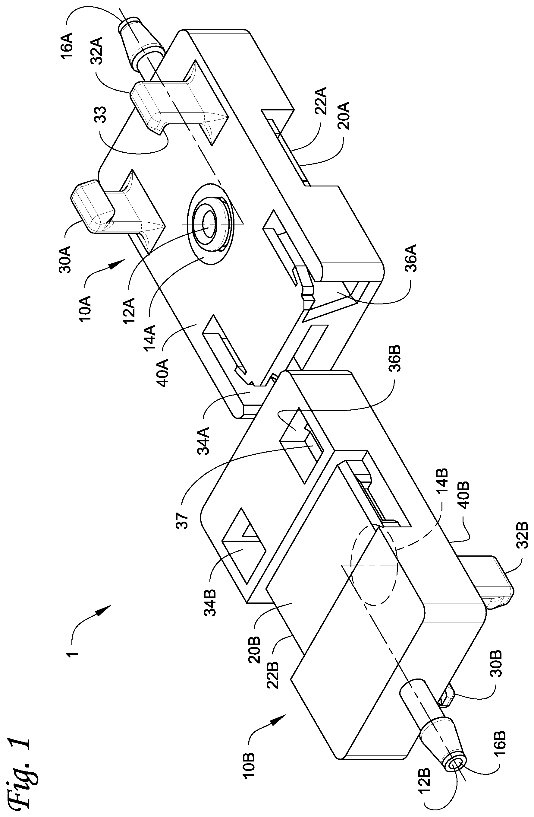
is a front perspective view of an embodiment of an aseptic low-temperature coupling assembly.
is a rear perspective view of a partial section of the aseptic low-temperature coupling assembly of , according to an embodiment.
is a sectional view of the aseptic low-temperature coupling assembly as indicated in , according to an embodiment.
is a schematic diagram of an embodiment of a low-temperature storage container aseptically connected to a processing device with an assembled aseptic low-temperature coupling assembly.
is a front perspective view of a second embodiment of an aseptic low-temperature coupling assembly.
is a sectional view of the aseptic low-temperature coupling assembly as indicated in , according to an embodiment.
is an upper perspective view of an embodiment of connector for an aseptic low-temperature coupling assembly.
Like numbers represent like features.
DETAILED DESCRIPTION
is a perspective view of an embodiment of an aseptic low-temperature coupling assembly 1 . The coupling assembly 1 includes a first connector 10 A and a second connector 10 B that are configured to couple together to form a sealed fluid connection. The first connector 10 A includes a first fluid passage 12 A that extends through the first connector 10 A. The second connector 10 B includes a second fluid passage 12 B that extends through the second connector 10 B. The first fluid passage 12 A and the second fluid passage 12 B are generally indicated with dashed lines in . When the first connector 10 A is coupled to the second connector 10 B, the first fluid passage 12 A and the second fluid passage 12 B are joined to form a sealed fluid connection that extends through the coupled connectors 10 A, 10 B.
The first fluid passage 12 A includes an opening 14 A disposed in the external surface of the first connector 10 A. For example, the opening 14 A is disposed in the upper surface 40 A of the first connector 10 A that faces the second connector 10 B when coupled. The first fluid passage 12 A also include a second opening 16 A at the opposite end of the first fluid passage 12 A. In an embodiment, the second opening 16 A may be the inlet of the first connector 10 A and the first opening 14 A may be the outlet of the first connector 10 A.
The second fluid passage 12 B includes an opening 14 B disposed in the external surface of the second connector 10 B. For example, the opening 14 B is disposed in a lower surface 40 B of the second connector 10 B (shown in ) that faces the first connector 10 A when coupled. The second fluid passage 12 B also include a second opening 16 B at the opposite end of the second fluid passage 12 B. For example, the first opening 14 B can be the inlet of the second fluid passage 12 B and the second connector 10 B and the second opening 16 B can be the outlet of the second fluid passage 12 B and the second connector 10 B. In the coupled connectors 10 A, 10 B, opening 16 A can be an inlet of the assembly 1 while the opening 16 B can be the outlet of the assembly 1 . The connection of the passages 12 A, 12 B in the coupled connector is discussed in more detail below.
The first connector 10 A and the second connector 10 B include retaining features 30 A, 30 B, 32 A, 32 B, 34 A, 34 B, 36 A, 36 B (retaining feature 36 A is obscured in ) that are used to couple the connectors 10 A, 10 B together. The retaining features include first retaining features 30 A, 32 A, 30 B, 32 B (one of the first retaining features 30 B is obscured in ) and corresponding second retaining features 34 A, 36 A, 34 B, 36 B. Each connector 10 A, 10 B has a first retaining features 30 A, 30 B and a second retaining feature 34 A, 34 B disposed on an opposite sides of the opening 14 A, 14 B of their respective fluid passage 12 A, 12 B.
The first and second retaining features 30 A, 32 A, 34 A, 36 A of the first connector 10 A engage with the first and second retaining features 30 B, 32 B, 34 B, 36 B of the second connector 10 B to couple together the first connector 10 A and the second connector 10 B. In the first connector 10 A and the second connector 10 B, first retaining feature 30 A/ 30 B, 32 A/ 32 B and second retaining feature 34 A/ 34 B, 36 A/ 36 B have a corresponding shape. A first retaining feature 30 A and a second retaining feature 34 A of the first connector 10 A have a corresponding shape. For example, a first retaining feature 30 A has a shape that would be capable of engaging with the second retaining feature 34 B. As shown in , the first connector 10 A can have the same number and configuration of retaining features as the second connector 10 B. For example, the first connector 10 A and the second connector 10 B can have the same general shape.
The connectors 10 A, 10 B are coupled together (e.g., as shown in ) by the first retaining features 30 A, 32 A, 30 B, 32 B engaging with the second retaining features 34 A, 36 A, 34 B, 36 B. The first retaining features 30 A, 32 A of the first connector 10 A engage corresponding second retaining features 34 B, 36 B of the second connector 10 B, and the first retaining features 30 B, 32 B of the second connector 10 B engage corresponding second retaining features 34 A, 36 A of the first connector 10 A. For example, first retaining feature 30 A engages with second retaining feature 34 B, first retaining feature 32 A engages with the second retaining feature 36 B, first retaining feature 30 B engages with second retaining feature 34 A, and first retaining feature 32 B engages with the second retaining feature 36 A.
The connectors 10 A, 10 B are genderless connectors. Each of the connectors 10 A, 10 B has at least one of the first retaining features 30 A, 30 B, 32 A, 32 B and at least one of the second retaining features 34 A, 34 B, 36 A, 36 B. In the illustrated embodiment, each of the connectors 10 A, 10 B includes two of the first retaining features 30 A/ 30 B, 32 A/ 32 B and two of the second retaining features 34 A/ 34 B, 36 A/ 36 B. In an embodiment, the first connector 10 A and the second connector 10 B may each have one first retaining feature 30 A, 30 B, 32 A, 32 B and one second retaining feature 34 A, 34 B, 36 A, 36 B.
The first connector 10 A and the second connector 10 B each include a plurality of the first retaining features 30 A, 32 A and a plurality of the second retaining features 34 A, 36 A. The first connector 10 A and the second connector 10 B can each include two of the first retaining features 30 A/ 30 B, 32 A/ 32 B and two of the second retaining features 34 A/ 34 B, 36 A/ 36 B. In an embodiment, the first connector 10 A may include one or more of the first retaining features 30 A, 32 A and one or more of the second retaining features 34 A, 36 A. In an embodiment, the second connector 10 B include at least one first retaining feature 30 B, 32 B and at least one second retaining feature 34 B, 36 B. Accordingly, each of the first connector 10 A and the second connector 10 B is a genderless connector as it includes both a male retaining feature (e.g., first retaining feature 30 A/ 30 B, 32 A/ 32 B) and a female retaining feature (e.g., second retaining feature 34 A/ 34 B, 36 A/ 36 B).
The first retaining features 30 A, 30 B, 32 A, 32 B can be any suitable structure for forming a mechanical connector with the complementary second retaining features 34 A, 34 B, 36 A, 36 B to form a snap-fit, pressure-fit, or the like. For example, each first retaining feature(s) 30 A, 32 A of the first connector 10 A can be any suitable structure for forming a mechanical connector with a respective complementary retaining feature 34 B, 36 B of the second connector 10 B. The retaining features can include, for example, slots, tabs, flanges, detents, hooks, or any other suitable structures for mechanical engagement with other structures. In the embodiment of , the first retaining features 30 A, 30 B, 32 A, 32 B include retaining projections.
Second retaining features 34 A, 34 B, 36 A, 36 B can be any suitable structure for forming a mechanical connector with the complementary first retaining features 30 A, 30 B, 32 A, 32 B to form a snap-fit, pressure-fit, or the like. For example, each first retaining feature(s) 30 A, 32 A of the first connector 10 A can be any suitable structure for forming a mechanical connector with a respective complementary retaining feature 34 B, 36 B of the second connector 10 B. The retaining features can include, for example, slots, tabs, flanges, detents, hooks, or any other suitable structures for mechanical engagement with other structures. In the embodiment of , the second retaining features 34 A, 34 B, 36 A, 36 B include retaining slots. The retaining slot(s) can extend all the way through their respective connector 10 A, 10 B.
The aseptic low-temperature coupling assembly 1 can include a pair of removable films 20 A, 20 B that can seal the first and second fluid passages 12 A, 12 B from the ambient environment prior to the coupling of the connectors 10 A, 10 B. The removable films 20 A, 20 B respectively cover and seal the openings of the respective first and second fluid passages 12 A, 12 B. For example, the first pull film 20 A covers and seals the opening 14 A of the first fluid passage 12 A, and the second pull film 20 B covers and seals the opening 14 B of the second fluid passage 12 B. The removable films 20 A, 20 B are configured to maintain the fluid passages 12 A, 12 B as aseptic prior to the coupling of the connectors 10 A, 10 B. For example, each pull film 20 A, 20 B prevents containments in the air (e.g., as dust, moisture, etc.) from entering the opening 14 A, 14 B of its respective fluid passage 12 A, 12 B that is used to fluidly connect the fluid passages 12 A, 12 B in the coupled connectors 12 A, 12 B. The opposite opening of each fluid passage 12 A, 12 B (e.g., opening 16 A of the first fluid passage 12 A, opening 16 B of the second fluid passage 12 B) can be attached to a sealed connection (e.g., tubing, a bioprocessing bag, etc.). The removable films 20 A, 20 B are removed once the connectors 10 A and 10 B have been connected. For example, the removable films 20 A, 20 B are removed after being compressed between the connected connectors 10 A, 10 B.
In an embodiment, the removable films 20 A, 20 B are pull films configured to be removed by being pulled off of the connectors 10 A, 10 B. The coupling compresses the pair of removable films 20 A, 20 B between the two connectors 10 A, 10 B. The assembly of the aseptic low-temperature coupling assembly 1 can include pulling on the compressed removable films 20 A, 20 B to remove the removable films 20 A, 20 B from the coupled connectors 10 A, 10 B. In an embodiment, the compressed removable films 20 A, 20 B are configured to be pulled on and removed simultaneously from between the coupled connectors 10 A, 10 B. For example, the connectors 10 A, 10 B compress removable films 20 A, 20 B along a first direction (e.g., compressed along direction D 2 in ), and the compressed removable films 20 A, 20 B are removed by being pulled in a second direction that is transverse to the first direction (e.g., pulled in direction D 3 in ).
The removable films 20 A, 20 B are attached to the connectors 10 A, 10 B in a manner that allows for the removable films 20 A, 20 B when compressed between the coupled connectors 10 A, 10 B to be simultaneously pulled on and simultaneously removed from between the connectors 10 A, 10 B. The attachment of removable films 20 A, 20 B allows for a user to simultaneously grasp both of the removable films 20 A, 20 B so that the removable films 20 A, 20 B can be simultaneously pulled on and removed. The configuration of the removable films 20 A, 20 B allows for a user, by hand, to grasp both removable films 10 A, 10 B and pull them in a transverse direction to the direction of compression (e.g., in transverse direction D 3 ). For example, the removable films 20 A, 20 B can each include an end 22 A, 22 B configured to be pulled away from their respective connector 10 A, 10 B. The ends 22 A, 22 B is configured to pull away from their connector 10 A, 10 B so form the entire removable films 20 A, 20 B into a planar shape, which can then be pulled in the single traverse direction to remove the compressed removable films 20 A, 20 B from between the two connectors 10 A, 10 B. The removable films 20 A, 20 B become entirely detached from connectors 10 A, 10 B once removed.
This configuration for the connectors 10 A, 10 B and removable films 20 A, 20 B allows for the opening of the first fluid passage 12 A and the opening of the second fluid passage 12 B remain sealed by their respective film 20 A, 20 B until the assembly 1 is assembled. This advantageously keeps the fluid passages 12 A, 12 B aseptic until they can form a sealed connection to each other in the coupled connectors 10 A, 10 B.
illustrates a prospective partial sectional view of the assembled aseptic low-temperature coupling assembly 1 , according to an embodiment. A sectional view of the second connector 10 B is shown in . Obscured features are shown in dashed lines in .
As shown in illustrated embodiment, the first retaining features can include a first retaining projection and a second retaining projection, and the second retaining features can include a first retaining slot and a second retaining slot. For example, first retaining feature 32 A is a first retaining projection that engages with second retaining feature 36 B that is a first retaining slot, and first retaining feature 32 B is a second retaining projection that engages with second retaining features 36 A that is a second retaining slot. In an embodiment, the other first retaining features 30 A, 30 B, 32 B may engage with their respective second retaining feature 34 A, 34 B, 36 A in a similar manner to the first retaining feature 32 A and second retaining feature 36 B shown in .
The retaining projection 32 A extends from an upper surface 40 A of the connector 10 A. The upper surface 40 A of the connector 10 A faces the opposite connector 10 B when the connectors 10 A, 10 B are connected. In the embodiment shown on , a tab 33 on the retaining projection 32 A forms a snap fit over a lip 37 of the retaining slot 36 B. The retaining projection 32 A engages with the retaining slot 36 B by being inserted into the retaining slot 36 B in a first direction D 1 , then moving the retaining projection 32 A in a second direction. The movement in the first direction D 1 aligns the retaining projection 32 A with the lip 37 within the retaining slot 36 B (e.g., aligns the retaining projection 32 A with the lip 37 in the horizontal direction D 1 ), and the movement in the second direction D 2 snap fits the tab 33 over and onto the lip 37 . For example, the movement in the first direction D 1 generally moves the connectors 10 A, 10 B perpendicular to each other, and the movement in the second direction D 2 moves the connectors 10 A, 10 B closer together.
The retaining slot 36 B can also include a bendable restraining member 41 that prevents removal of the retaining projection 32 A once inserted into the retaining slot 36 B. The insertion of the retaining projection 32 A into the retaining slot 36 B in the first direction D 1 bends the restraining member 41 . For example, after the retaining projection 32 A is full inserted into retaining slot 36 B in the first direction D 1 , the restraining member 41 limits the movement of the retaining projection 32 A along the first direction D 1 (e.g., limits movement of the retaining projection 32 A in the opposite direction). The restraining member 41 is configured to allow the pertaining projection 32 A to be moved in the second direction D 2 to snap fit the tab 33 with the lip 37 .
shows a sectional view of the assembled aseptic low-temperature coupling assembly 1 , according to an embodiment. The sectional view of is indicated in . shows the connecting of the first fluid passage 12 A of the first connector 10 A with the second fluid passage 12 B of the second connector 10 B in the assembled aseptic low-temperature coupling assembly 1 . As shown in , when coupled together, the first connector 10 A can be configured to only directly contact the second connector 10 B via their retaining features. For example, a gap 44 is provided between main opposing surfaces 40 A, 40 B of the connectors 10 A, 10 B (e.g., between the upper surface 40 A of the first connector 10 A and the lower surface 40 B of the second connector 10 B).
The first fluid passage 12 A includes the opening 14 A disposed in the external surface of the first connector 10 A. For example, as shown in , the opening 14 A is disposed in the upper surface 40 A of the first connector 10 A that faces the second connector 10 B when coupled. The first fluid passage 12 A also include a second opening 16 A at the opposite end of the first fluid passage 12 A. For example, the first opening 14 A can be configured to be an inlet of the first connector 10 A and the second opening 16 A can be configured to be an outlet of the first connector 10 A.
The second fluid passage 12 B includes an opening 14 B disposed in the external surface of the second connector 10 B. For example, as shown in , the opening 14 B is disposed in a lower surface 40 B of the second connector 10 B that faces the first connector 10 A when coupled. The second fluid passage 12 B also include a second opening 16 B at the opposite end of the second fluid passage 12 B. For example, the first opening 14 B can be the inlet of the second fluid passage 12 B and the second connector 10 B and the second opening 16 B can be the outlet of the second fluid passage 12 B and the second connector 10 B. In the coupled connectors 10 A, 10 B, opening 16 A can be an inlet of the assembly 1 while the opening 16 B can be the outlet of the assembly 1 .
As shown in , the opening 14 A of the first fluid passage 12 A is aligned with the opening 14 B of the second fluid passage 12 B in the coupled connectors 10 A, 10 B. The openings 14 A, 14 B aligned by overlapping at least partially. As shown in , the openings being aligned and overlapping with respect to the second direction D 2 (e.g., in the vertical direction).
The assembly aseptic low-temperature coupling assembly 1 includes a first gasket 70 and a second gasket 75 . The first gasket 70 is obscured in as it is covered by the first pull film 20 A. Prior to coupling, the pull film 20 A (shown in ) is disposed over and seals the first gasket 70 and the first fluid passage 12 A. For example, the pull film 20 A covers and forms a seal over the opening 14 A and the first gasket 70 disposed in the opening 14 A of the first fluid passage 12 A. In a similar manner, pull film 20 B (shown in ) is disposed over and seals the second gasket 75 and the second fluid passage 12 B. As discussed above, the coupling of the connectors 10 A, 10 B compresses the removable films 20 A, 20 B between the connectors 10 A, 10 B. More specifically, the removable films 20 A, 20 B are compressed between the two gaskets 70 , 75 . The coupling of the connectors 10 A, 10 B pinches the removable films 20 A, 20 B between the two gaskets 70 , 75 . For example, the removable films 20 A, 20 B are pinched between the top of the first gasket 70 and the bottom of the second gasket 75 .
As shown in , the first gasket 70 is disposed in the first connector 10 A and the second gasket 75 is disposed in the second connector 10 B. The first gasket 70 is disposed in the first fluid passage 12 A of the first connector 10 A. The second gasket 75 is disposed in the second fluid passage 12 B of the second connector 10 B. More particularly, the first gasket 70 is disposed in an end portion of the first fluid passage 12 A and extends out through the opening 14 A of the first fluid passage 12 A. The second gasket 75 is disposed in an end portion of the second fluid passage 12 B and extends out through the opening 14 B of the second fluid passage 12 B. As shown in , the first gasket 70 and the second gasket 75 are each disposed between the opening 14 A of the first fluid passage 12 A and the opening 14 B of the second fluid passage 12 B. More particularly, the end portion of each gasket 70 , 75 is disposed between the opening 14 A of the opening 14 A of the first fluid passage 12 A and the opening 14 B of the second fluid passage 12 B.
In the illustrated embodiment, the gaskets 70 , 75 have a cylinder shape. In other embodiments, the gaskets 70 , 75 may have different shape. For example, the first gasket 70 in an embodiment may have an O-ring shape.
The coupling of the first connector 10 A and the second connector 10 B includes moving the connectors 10 A, 10 B closer together to engage their corresponding retaining features (e.g., moving the first connector 10 A in direction D 2 in , moving the second connector 10 B in the direction D 3 in , and the like). The coupling of the first connector 10 A and the second connector 10 B compresses the first gasket 70 and the second gasket 75 between the first connector 10 A and the second connector 10 B. The coupling of the connectors 10 A, 10 B pushes the first gasket 70 against the second gasket 75 and compresses the gaskets 70 , 75 . The first gasket 70 is compressed between the first connector 10 A and the second gasket 75 . The second gasket 75 is compressed between the second connector 10 B and the first gasket 70 .
As shown in , the compressed gaskets 70 , 75 form a channel 42 that fluidly connects the first fluid passage 12 A to the second fluid passage 12 B in a sealed manner. The compression of the gaskets 70 , 75 against each other and the connectors 10 A, 10 B provides a sealed connection between the first and second fluid passages 12 A, 12 B. The coupling of the connectors 10 A, 10 B as shown in , connects the first fluid passage 12 A with the second fluid passage 12 B to form a sealed fluid connection that extends through the coupled connectors 10 A, 10 B. In an embodiment, fluid can then flow through the sealed fluid connection formed in the assembled coupler assembly 1 as shown by the dashed arrow in . For example, the opening 16 A of the first fluid passage 12 A acts as the inlet for the sealed fluid connection while the opening 16 B of the second fluid passage 12 B acts as the outlet for the sealed fluid connection.
is a schematic diagram of a bioprocessing bag 90 aseptically connected to a processing device 92 using the assembled aseptic low-temperature coupling assembly 1 . For example, the processing equipment 92 can include equipment that supplies the process material or reactants that form the process material to the fill the bag 90 and/or equipment that utilizes the process material stored within the bioprocessing bag 90 . Bioprocessing bag 90 is an example of a low-temperature fluid storage container. An inlet of the assembly 1 (e.g., opening 16 A of the first connector 10 A) is fluidly connected to the bioprocessing bag 90 and the outlet 2 (e.g., opening 16 B of the second connector 10 B) is fluidly connected to the processing equipment 92 . For example, the inlet of the assembly 1 is configured to be inserted into tubing 96 that connects to the bioprocessing bag 90 , and the outlet of the assembly 1 is configured to be inserted into tubing 98 that connects to the processing equipment 92 . In another embodiment, the inlet of assembly 1 (e.g., opening 16 A of the first connector 10 A) may be configured to be directly attached (e.g., molded, fused, or the like) to the bioprocessing bag 90 .
The filled bioprocessing bag 90 is configured to be stored at frozen temperatures (e.g., temperatures of less than 0° C.). For example, the bag holder 94 can be configured to hold the bioprocessing bag 90 within a freezing system (e.g., a blast chiller, low temperature freezer, or the like). In an embodiment, the bioprocessing bag 90 is configured to be stored at a temperature of −50° C. or lower. In an embodiment, the bioprocessing bag 90 is configured to be stored at cryogenic temperatures of −150° C. or lower. In an embodiment, the bioprocessing bag 90 is configured to be stored at cryogenic temperatures of −190° C. or lower. As shown in , the first connector 10 A and the second connector 10 B are configured so as to be disposable within the bag holder 94 along with the bag 90 . For example, the first connector 10 A is configured to be disposed in bag holder 94 along with the bag 90 during freezing.
The assembly 1 is configured to form a sealed connection after being frozen and then heated back to ambient temperature with the bioprocessing bag 90 . For example, the assembly 1 is configured to provide a sealed connection after being frozen to the storage temperature of the bag 90 and then being heated (e.g., applying heat to the bioprocessing bag 90 , exposing the bioprocessing bag 90 to ambient temperature, or the like). The first connector 10 A after being frozen with the bioprocessing bag 90 and then being heated back to above freezing (e.g., to ambient temperature) is connected with the second connector 10 B to form the sealed connection. In an embodiment, the second connector 10 B is not frozen with the first connector 10 A and the bag 90 . For example, ambient temperature is at or about 20° C. The first connector 10 A, the second connector 10 B, and the gaskets 70 , 75 are formed to have no substantial deformation after being cooled to at least −50° C. then heated to ambient temperature. Substantial deformation includes, for example, visible cracking in the material, a shrinkage or expansion relative to its original shape at ambient temperature that can interfere with the connection of first connector 10 A to second connection 10 B or adversely affect sealing of said connection. The gaskets 70 , 75 are each formed to have no substantial deformation by being made of a material that does remains elastic when cooled even to temperatures such as liquid nitrogen temperatures. In embodiments, suitable gaskets showing no substantial deformation at low temperatures can be determined by testing including, as non-limiting examples, temperature retraction testing and/or brittleness testing. Temperature retraction testing can be performed according to ASTM D1329, ISO 2921, or any other suitable testing methodology for determining suitable retraction properties of the material at temperatures where the gasket may be used. Brittleness testing can be performed according to ASTM D2137, ISO 28702, or any other suitable testing methodology for determining resistance to cracking at temperatures where the gasket may be used.
The first connector 10 A and its attached pull film 20 A and the second connector 10 B and its attached second pull film 20 B are each formed to have no substantial deformation after returning to ambient temperature from a temperature of −50° C. or lower. The connectors 10 A, 10 B and the pull films 20 A are each formed of polymer material that does not exhibit any visible cracking and maintains the seal of the first opening 14 A by the first pull film 20 A and the second opening 14 B by the second pull film 20 B when cooled to a temperature after returning to ambient temperature from a temperature of −50° C. or lower. The connectors 10 A, 10 B may be made of the same or a different type of polymer material. The pull films 20 A, 20 B may be made of the same or a different type of polymer material. In an embodiment, each of the first connector 10 A and its attached pull film 20 A and the second connector 10 B and its attached second pull film 20 B is formed to have no substantial deformation after returning to ambient temperature from a temperature of −150° C. or lower. In such an embodiment, the connectors 10 A, 10 B and pull films 20 A, 20 B are each formed of a polymer material that does not exhibit any visible cracking and maintains the seal of the first opening 14 A by the first pull film 20 A and the second opening 14 B by the second pull film 20 B after returning to ambient temperature from a temperature of −150° C. or lower. In an embodiment, the connectors 10 A, 10 B and pull films 20 A, 20 B are formed of a polymer material that does not exhibit any substantial deformation after returning to ambient temperature from a temperature of −190° C. or lower. In such an embodiment, the connectors 10 A, 10 B and pull films 20 A, 20 B are each formed of a polymer material that does not exhibit any visible cracking and maintains the seal of the first opening 14 A by the first pull film 20 A and the second opening 14 B by the second pull film 20 B after returning to ambient temperature from a temperature of −190° C. or lower. For example, this can allow the assembly 1 to be used in cryogenic storage temperatures.
The polymer material(s) of the connectors 10 A, 10 B is a generally polymer that is generally non-reactive (e.g., non-reactive with air, non-reactive with the process material or the reactants used in a bioprocessing bag). For example, each of the connectors 10 A, 10 B in an embodiment comprise a fluoropolymer. The polymer material(s) of the connectors 10 A, 10 B has rigidity at ambient temperature sufficient for compressing the gaskets 70 , 75 between the connectors 10 A, 10 B to form the sealed connection between the fluid pathways 12 A, 12 B and preventing accidental disengagement of the engaged first and second retaining features.
The polymer material(s) of the pull films 20 A, 20 B is a generally polymer that is generally non-reactive (e.g., non-reactive with air, non-reactive with process material or reactants used in a bioprocessing bag). The polymer material of the gaskets 70 , 75 at ambient temperature has compressibility that causes the gasket(s) 70 , 75 when compressed between the connectors 10 A, 10 B to form the sealed connection between the fluid pathways 12 A, 12 B. For example, the gaskets 70 , 75 in an embodiment comprise one or more of silicone and ethylene-vinyl acetate (EVA).
is a perspective view of another embodiment of an aseptic low-temperature coupling assembly 101 . The coupling assembly 101 includes a first connector 110 A and a second connector 110 B that couple together to form a sealed fluid connection. The first connector 110 A includes a first fluid passage 112 A that extends through the first connector 110 A. The second connector 110 B includes a second fluid passage 112 B that extends through the second connector 10 B. The first fluid passage 112 A and the second fluid passage 112 B are generally indicated in dashed lines in . The connectors 110 A, 110 B can be made of a similar material as discussed above for the connectors 10 A, 10 B of the assembly 1 in .
The coupling assembly 101 includes a pair of pull films (not shown) that are omitted for illustration purposes. A first pull film covers and seals the first fluid passage 112 A and the second pull film covers and seals the second fluid passage 112 B. The pulls films can be attached to each connector 110 A, 110 B and cover their respective fluid passage 112 A, 112 B in a similar manner to the pulls films 20 A, 20 B as discussed for the assembly 1 in .
The connectors 110 A, 110 B include first retaining features 130 A, 130 B and second retaining features 134 A, 134 B. Each of the connectors 110 A, 110 B has at least one of the first retaining features 130 A, 130 B, and at least one of the second retaining features 134 A, 134 B. The connectors 110 A, 110 B are coupled together (e.g., as shown in ) by first retaining features 130 A, 130 B engaging with second retaining features 134 A, 134 B, as similarly discussed for the connectors 10 A, 10 B in . The first retaining feature 130 A of the first connector 110 A engages a corresponding second retaining feature 134 B of the second connector 110 B, and first retaining feature 130 B of the second connector 110 B engages corresponding second retaining feature 134 A of the first connector 110 A. For example, first retaining feature 130 A engages with second retaining feature 134 B, first retaining feature 130 B engages with the second retaining feature 134 A.
The first retaining features 130 A, 130 B can have a structure as similarly discussed above regarding the first retaining features of the connectors 10 A, 10 B in . The second retaining features 134 A, 134 B can have a structure as similarly discussed above with respect to the second retaining features of the connectors 10 A, 10 B in . The first retaining features 130 A, 130 B engage with corresponding second retaining features 134 A, 134 B to couple the connectors 110 A, 110 B together. For example, first retaining feature 130 A can include a retaining projection with a tab 133 and second retaining feature 134 B can be a retaining slot. As shown in the illustrated embodiment, the first retaining feature 130 A on the first connector 110 A can include a pair of retaining projections that each include a tab 133 . In an embodiment, first retaining feature 130 A can include a single retaining projection.
The first connector 110 A and the second connector 110 B are moved towards each other in a first direction D 4 to engage their corresponding retaining features 130 A, 130 B, 134 A, 134 B and couple the connectors (e.g., moving the first connector 110 A in the direction D 4 in , moving the second connector 110 B in an opposite direction of direction D 4 in ). In contrast to the assembly 1 in , movement of the connectors 110 A, 110 B along a single direction D 4 couples the connectors 110 A, 110 B together.
The first fluid passage 112 A includes an opening 114 A disposed in the external surface of the first connector 110 A. For example, as shown in , the opening 114 A is disposed in an upper surface of the first connector 110 A that faces the second connector 110 B when coupled. The first fluid passage 112 A also include a second opening 116 A at the opposite end of the first fluid passage 112 A. For example, the first opening 114 A can be configured to be an inlet of the first connector 110 A and the second opening 116 A can be configured to be an outlet of the first connector 110 A.
The second fluid passage 112 B includes an opening 114 B disposed in the external surface of the second connector 110 B. For example, as shown in , the opening 114 B is disposed in a lower surface of the second connector 110 B that faces the first connector 110 A when coupled. The second fluid passage 112 B also include a second opening 116 B at the opposite end of the second fluid passage 112 B. For example, the first opening 114 B can be the inlet of the second fluid passage 112 B and the second connector 110 B and the second opening 116 B can be the outlet of the second fluid passage 112 B and the second connector 110 B. In the coupled connectors 110 A, 110 B, opening 116 A can be an inlet of the assembly 101 while the opening 116 B can be the outlet of the assembly 101 .
A first gasket 170 is disposed in the opening 116 A of the first fluid passage 112 A and a second gasket 175 is disposed in the opening 116 B of the second fluid passage 112 B. The gaskets 170 , 175 can have a similar configuration in the first and second connectors 110 A, 110 B as discussed above for the gaskets 70 , 75 in the first and second connectors 10 A, 10 B of . The gaskets 170 , 175 can be formed of the same material as discussed above for the gaskets 70 , 75 in the assembly 1 of .
is a sectional view of the assembled coupling assembly 101 . The sectional view is a horizontal plane along the line indicated in . The coupling of the first connector 110 A and the second connector 110 B includes moving the connectors 110 A, 110 B closer together to engage their corresponding retaining features (e.g., moving the first connector 110 A in direction D 4 in , moving the second connector 110 B in the opposite downward in ). The coupling of the first connector 110 A and the second connector 110 B compresses the first gasket 170 and the second gasket 175 between the first connector 110 A and the second connector 110 B. The coupling of the connectors 110 A, 110 B pushes the first gasket 170 against the second gasket 175 and compresses the gaskets 170 , 175 . The first gasket 170 is compressed between the first connector 110 A and the second gasket 175 . The second gasket 175 is compressed between the second connector 110 B and the first gasket 170 .
As shown in , the compressed gaskets 170 , 175 form a channel 142 that fluidly connects the first fluid passage 112 A to the second fluid passage 112 B in a sealed manner. The compression of the gaskets 170 , 175 against each other and the connectors 110 A, 110 B provides a sealed connection between the first and second fluid passages 112 A, 112 B. The coupling of the connectors 110 A, 110 B as shown in , connects the first fluid passage 112 A with the second fluid passage 112 B to form a sealed fluid connection that extends through the coupled connectors 110 A, 110 B. In an embodiment, fluid can then flow through the sealed fluid connection formed in the assembled coupler assembly 101 as shown by the dashed arrow in . For example, the opening 116 A of the first fluid passage 112 A acts as the inlet for the sealed fluid connection while the opening 116 B of the second fluid passage 112 B acts as the outlet for the sealed fluid connection.
As shown in the embodiment of , a tab 133 on the retaining projection of first retaining feature 130 A forms a snap fit over a lip 137 of the retaining slot of the second retaining feature 134 B. The retaining slot can also include multiple lips 137 , 139 for engaging with the retaining projection. A first lip 139 is at a first depth in the retaining slot, and the second lip 137 at a second depth in the retaining slot. For example, the first lip 139 may be used to initially couple the first connector 110 A to the second connector 110 B, and the second lip 137 may be used for compressing the gaskets 70 , 75 to the desired compression for the assembled assembly 101 . The two retaining projections can be configured to be pushed together to fit into and past the lip 133 . For example, the two retaining projections configured to be pinched together to fit into and the past the lip 133 .
is an upper perspective view of a connector 210 for an aseptic low-temperature coupling assembly. An aseptic low-temperature coupling assembly includes two of the connectors 230 which are configured to couple to each other to form a sealed fluid connection, in a generally similar manner to the connectors 10 A, 10 B of the assembly 1 in and the connectors of the assembly in .
The connector 210 generally has features similar to the first connector 110 A in except for the configuration of the first retaining feature 230 and the second retaining feature 234 . For example, the connector 210 includes a fluid passage 212 (generally indicated in dashed lines in ) that extends through the first connector 210 and that includes a first opening 214 and a second opening 216 disposed at an opposite end of the fluid passage 212 . A gasket 270 is disposed in the connector 210 . For example, the gasket 270 can have a similar configuration in the connector 210 as discussed above for the gasket 70 and the first connector 10 A in the assembly 1 of .
The connector 210 includes first retaining feature 230 and second retaining feature 234 . The first retaining feature 230 includes two retaining projections and the second retaining feature 234 includes a retaining slot. The retaining slot including a pair of lips 233 , 235 disposed on opposite sides of the retaining slot. The two retaining projections configured to bending closer together to fit past the lips 233 , 235 in the opposing connector. For example, the retaining projections are pinched together to fit past the lips 233 , 235 in the retaining slot.
Aspects:
Any of aspects 1-15 can be combined with any of aspects 16-18.
Aspect 1. An aseptic low-temperature coupling assembly, comprising: a first connector including a first fluid passage extending through the first connector, the first fluid passage including an opening; a second connector including a second fluid passage extending through the second connector, the second fluid passage including an opening, the first connector and the second connector each including a first retaining feature and a second retaining feature, disposed on opposite sides of the opening in the respective one of the first connector and the second connector, wherein the first retaining feature and the second retaining feature have complementary shapes, and a first gasket disposed in one of the first connector and the second connector, wherein the first connector and the second connector are configured to be coupled together by the first and second retaining features of the first connector engaging with the first and second retaining features of the second connector, in which the opening of the first fluid passage aligns with the opening of the second fluid passage, and the first gasket are formed to have no substantial deformation after being cooled to at least −50° C. then heated to ambient temperature.
Aspect 2. The aseptic low-temperature coupling assembly of Aspect 1, wherein the coupling of the first connector and the second connector compresses the first gasket between the first connector and the second connector, in which the first gasket is disposed between the opening of the first fluid passage and the opening of the second fluid passage.
Aspect 3. The aseptic low-temperature coupling assembly of any one of Aspects 1 and 2, further comprising: a first removable film disposed over and sealing the opening of the first fluid passage; and a second removable film disposed over and sealing the opening of the second fluid passage.
Aspect 4. The aseptic low-temperature coupling assembly of Aspect 3, wherein in the coupling of the first connector and the second connector, the first removable film and the second removable film are compressed between the first connector and the second connector, and the first removable film and the second removable film configured to be removable while compressed between the first connector and the second connector.
Aspect 5. The aseptic low-temperature coupling assembly of any one of Aspects 1-4, further comprising: a second gasket disposed in the second connector, the first gasket being disposed in the first connector, wherein the coupling of the first connector and the second connector pushes the first gasket against the second gasket and compresses both the first gasket and the second gasket between the first connector and the second connector.
Aspect 6. The aseptic low-temperature coupling assembly of any one of aspects of 1-5, wherein the first retaining features include a first retaining projection and a second retaining projection, the second retaining features include a first retaining slot and a second retaining slot, the first retaining projection being inserted into the first retaining slot and the second retaining projection being inserted into the second retaining slot to couple the first connector and the second connector.
Aspect 7. The aseptic low-temperature coupling assembly of Aspect 6, wherein the first connector includes the first retaining projection and the first retaining slot, and the second connector includes the second retaining projection and the second retaining slot.
Aspect 8. The aseptic low-temperature coupling assembly of any one of Aspects 6 and 7, wherein the first retaining projection and the second retaining projection have the same shape.
Aspect 9. The aseptic low-temperature coupling assembly of any one of Aspects 1-8, wherein the first connector is formed of a polymer material that does not have substantial deformation after being cooled to at least −50° C. then heated back to the ambient temperature.
Aspect 10. The aseptic low-temperature coupling assembly of any one of Aspects 1-9, wherein the first connector is formed of a polymer material that does not exhibit cracking and maintains a seal after being cooled to at least −190° C. then heated back to the ambient temperature.
Aspect 11. The aseptic low-temperature coupling assembly of any one of Aspects 1-10, wherein the first connector, the second connector, and the first gasket are configured to provide a sealed fluid connection after being cooled to at least −50° C. then heated back to the ambient temperature.
Aspect 12. The aseptic low-temperature coupling assembly of any one of Aspects 1-1, wherein the first connector comprises fluoropolymer.
Aspect 13. The aseptic low-temperature coupling assembly of any one of Aspects 1-12, wherein the first gasket comprises one or more of silicone and ethylene-vinyl acetate (EVA).
Aspect 14. The aseptic low-temperature coupling assembly of any one of Aspects 1-13, wherein the gasket does not exhibit abnormalities when tested at −190° C. according to method B of ISO Standard 28702.
Aspect 15. The aseptic low-temperature coupling assembly of any one of Aspects 1-15, wherein the first connector and the second connector are configured to couple so as to be disposable within a bag holder along with a bag, the first connector configured to be fluidly connected to the bag.
Aspect 16. A method of aseptically connecting a low-temperature fluid storage container, the method comprising: coupling a first connector to a second connector via first retaining features and second retaining features, a first fluid passage extending through the first connector and a second fluid passage extending through the second connector, the first fluid passage and the second fluidly passage each including an opening, wherein coupling the first connector to the second connector includes: engaging the first retaining features with the second retaining features, the first connector and the second connector each including one of the first retaining features and one of the second retaining features disposed on opposite sides of the opening in the respective one of the first connector and the second connector, compressing a first gasket between the first connector and the second connector, the first gasket disposed in one of the first connector and the second connector, and aligning the opening of the first fluid passage with the opening of the second fluid passage, wherein the first gasket are formed to have no substantial deformation after being heated to ambient temperature from a temperature of at least −50° C.
Aspect 17. The method of Aspect 16, further comprising: compressing, between the first connector and the second connector, each of a first pull film disposed over the outlet of the first fluid passage and a second pull film disposed over the opening of the second fluid passage, simultaneously removing the first pull film and the second pull film compressed between the first connector and the second connector by simultaneously pulling the first pull film and the second pull film in a transverse direction.
Aspect 18. The method of Aspect 17, further comprising: compressing a second gasket between the first connector and the second connector, the first gasket disposed in the first connector, and the second gasket disposed in the second connector, wherein prior to removal, the first pull film is disposed over and seals the first passageway and the first gasket.
The examples disclosed in this application are to be considered in all respects as illustrative and not limitative. The scope of the invention is indicated by the appended claims rather than by the foregoing description; and all changes which come within the meaning and range of equivalency of the claims are intended to be embraced therein.
Figures (7)
Citations
This patent cites (17)
- US3865411
- US4418945
- USRE32056
- US9335000
- US9364653
- US9770581
- US10267443
- US20090015005
- US20130207380
- US20190083772
- US20210062946
- US20210095802
- US2961688
- US102013214068
- US2665502
- US20160146828
- USWO-8402321