Abstract
The fixing device includes a limiting structure and a movement portion. The limiting structure is extended along a first direction and has an accommodation space and at least one pair of hooks disposed at a terminal end of the limiting structure. The extending directions of the at least one pair of hooks are opposite to each other and parallel to a second direction. The movement portion moves relative to the limiting structure. When a bottom of the movement portion is disposed above the at least one pair of hooks, the at least one pair of hooks has a first distance therebetween in the second direction. When the bottom of the movement portion overlaps the at least one pair of hooks in the second direction, the at least one pair of hooks has a second distance greater than the first distance therebetween in the second direction.
Claims (20)
1. A fixing device comprising: a limiting structure extended along a first direction and having an accommodation space and at least one pair of hooks disposed at a terminal end of the limiting structure, wherein extending directions of the at least one pair of hooks are opposite to each other and respectively are parallel to a second direction perpendicular to the first direction; and a movement portion disposed in the accommodation space and configured to move relative to the limiting structure; when a bottom of the movement portion is disposed above the at least one pair of hooks, the at least one pair of hooks has a first distance therebetween in the second direction; when the bottom of the movement portion overlaps the at least one pair of hooks in the second direction, the at least one pair of hooks has a second distance greater than the first distance therebetween in the second direction; wherein a positioning groove is formed on the limiting structure and is configured to accommodate a protruded portion of the movement portion, the positioning groove comprises a first portion and a second portion, an extending direction of the first portion is different from an extending direction of the second portion, the protruded portion is able to move freely in the first portion, and the protruded portion is able to be positioned in the second portion.
14. A fixing device comprising: a limiting structure extended along a first direction and having an accommodation space and at least one pair of hooks disposed at a terminal end of the limiting structure, wherein extending directions of the at least one pair of hooks are opposite to each other and respectively are parallel to a second direction perpendicular to the first direction, and the limiting structure comprises a first limiting member and a second limiting member; and a movement portion disposed in the accommodation space and configured to move relative to the limiting structure, wherein at least one portion of the movement portion is disposed between the first limiting member and the second limiting member, wherein the first limiting member comprises: a main portion; an upper end opening; a lower end opening opposite to the upper end opening; and a rear side opening interconnected with the upper end opening, the lower end opening and the accommodation space; wherein the first limiting member comprises a first structure and a second structure and is connected to the main portion, the first structure and the second structure correspond to the lower end opening, and a gap is formed between the first structure and the second structure; when a bottom of the movement portion is disposed above the at least one pair of hooks, the at least one pair of hooks has a first distance therebetween in the second direction; when the bottom of the movement portion overlaps the at least one pair of hooks in the second direction, the at least one pair of hooks has a second distance greater than the first distance therebetween in the second direction; wherein the second limiting member comprises: an upper end hole; a lower end hole opposite to the upper end hole; and a front side opening interconnected with the upper end hole, the lower end hole and the accommodation space, wherein the first limiting member and the second limiting member are assembled and surround the accommodation space.
Show 18 dependent claims
2. The fixing device according to claim 1 , wherein the limiting structure comprises a first limiting member and a second limiting member, and at least one portion of the movement portion is disposed between the first limiting member and the second limiting member.
3. The fixing device according to claim 2 , wherein the first limiting member comprises: an upper end opening; a lower end opening opposite to the upper end opening; and a front side opening interconnected with the upper end opening, the lower end opening and the accommodation space, wherein the front side opening exposes a portion of the second limiting member and the movement portion.
4. The fixing device according to claim 3 , wherein the first limiting member comprises two blocking pieces corresponding to the lower end opening and extended to inside of the first limiting member, wherein extending directions of the two blocking pieces are parallel to the second direction.
5. The fixing device according to claim 4 , wherein the second limiting member comprises: a body portion; two extending portions connected to the body portion, wherein the at least one pair of hooks are formed at bottoms of the two extending portions; two side grooves disposed on two opposite sides of the body portion; and a rear end groove disposed between the two side grooves, wherein the two side grooves are separated from each other.
6. The fixing device according to claim 5 wherein the movement portion comprises: a core portion; two side fixing members connected to the core portion, wherein terminal ends of the two side fixing members respectively have a latch structure; and a middle fixing member connected to the core portion and disposed between the two side fixing members, wherein the middle fixing member comprises a rod portion and an expanded portion connected to the rod portion, and a width of the expanded portion in the second direction is greater than a width of the rod portion in the second direction.
7. The fixing device according to claim 6 , wherein the two side grooves of the body portion of the second limiting member have a plurality of notches, the two side grooves are used to accommodate the two side fixing members, and each of the notches is engaged with the latch structure.
8. The fixing device according to claim 2 , further comprising an upper cover, wherein two sides of the upper cover respectively have a fixing mechanism, two sides of the first limiting member respectively have a through hole, and the fixing mechanism is used to engage with the through hole.
9. The fixing device according to claim 2 , wherein the first limiting member comprises: a main portion; an upper end opening; a lower end opening opposite to the upper end opening; and a rear side opening interconnected with the upper end opening, the lower end opening and the accommodation space; wherein the first limiting member comprises a first structure and a second structure and is connected to the main portion, the first structure and the second structure correspond to the lower end opening, and a gap is formed between the first structure and the second structure.
10. The fixing device according to claim 9 , wherein the first limiting member has a positioning groove interconnected with the upper end opening, and the positioning groove has a S-shaped appearance.
11. The fixing device according to claim 10 , further comprising at least one slit adjacent to the positioning groove.
12. The fixing device according to claim 9 , wherein the first limiting member has the positioning groove, and the positioning groove is adjacent to the upper end opening.
13. The fixing device according to claim 12 , wherein the positioning groove further comprises a third portion, and an extending direction of the third portion is intersected with the extending direction the second portion.
15. The fixing device according to claim 14 , wherein the second limiting member further comprises: a rear side housing; a side housing connected to the rear side housing; and a fixing mechanism connected to the rear side housing, wherein the fixing mechanism and the side housing are stacked in the first direction, and a gap is formed between the fixing mechanism and the side housing.
16. The fixing device according to claim 14 , wherein the first limiting member further comprises a side through hole, the side through hole is disposed on a side wall of the first limiting member and corresponds to the fixing mechanism, and as the fixing mechanism and the side through hole are mutually engaged, the first limiting member and the second limiting member are mutually fixed.
17. The fixing device according to claim 2 , wherein the movement portion comprises: an expanded portion; a rod portion connected to the expanded portion and passing through the accommodation space along the first direction, wherein a width of the expanded portion in the second direction is greater than a width of the rod portion in the second direction; and a protruded portion disposed on the rod portion, wherein, as the protruded portion and a positioning groove of the first limiting member are mutually engaged, the movement portion and the first limiting member are mutually fixed.
18. The fixing device according to claim 17 , further comprising a spring structure, the spring structure surrounds the rod portion and enables the movement portion to perform reciprocal movement along an axis parallel to the first direction.
19. The fixing device according to claim 2 , wherein the pair of hooks are engaged with a counter member.
20. The fixing device according to claim 19 , wherein a back of the first limiting member is fixed on a first plate structure, and a bottom of the counter member is fixed on a second plate structure.
Full Description
Show full text →
BACKGROUND OF THE INVENTION
This application claims the benefit of People's Republic of China application Serial No. 202010789376.0, filed Aug. 7, 2020, the subject matter of which is incorporated herein by reference.
Field of the Invention
The invention relates in general to a fixing device and more particularly to a fixing device having a movement portion.
Description of the Related Art
In general, two plate structures are mounted together using screws or plugs through the use of hand tool or electrical tool and require a large amount of operation time and labor. Therefore, the assembly and disassembly of two plate structures cannot be done efficiently.
Therefore, it has become a prominent task for the industries to provide a fixing device to improve the efficiency in the assembly and disassembly of two plate structures.
SUMMARY OF THE INVENTION
The present invention relates to a fixing device capable of resolving the above problems. The fixing device includes a limiting structure and a movement portion. The limiting structure includes a pair of hooks. When the movement portion moves relative to the limiting structure, the distance between the hooks can be adjusted, such that the two plate structures connected to the fixing device can be mutually fixed in an easy and timesaving manner.
According to one embodiment of the present invention, a fixing device is provided. The fixing device includes a limiting structure and a movement portion. The limiting structure is extended along a first direction and has an accommodation space and at least one pair of hooks located at the terminal end of the limiting structure. The extending directions of the at least one pair of hooks are opposite to each other and respectively are parallel to a second direction perpendicular to the first direction. The movement portion is disposed in the accommodation space and moves relative to the limiting structure. When a bottom of the movement portion is disposed on at least one pair of hooks, the at least one pair of hooks has a first distance therebetween in the second direction. When the bottom of the movement portion overlaps the at least one pair of hooks in the second direction, the at least one pair of hooks has a second distance greater than the first distance therebetween in the second direction.
The benefit of the present invention is as follows: when the movement portion of the fixing device moves relative to the limiting structure, the distance between the hooks can be adjusted, such that the two plate structures connected to the fixing device can be mutually fixed in an easy and timesaving manner.
The above and other aspects of the invention will become better understood with regard to the following detailed description of the preferred but non-limiting embodiment (s). The following description is made with reference to the accompanying drawings.
BRIEF DESCRIPTION OF THE DRAWINGS
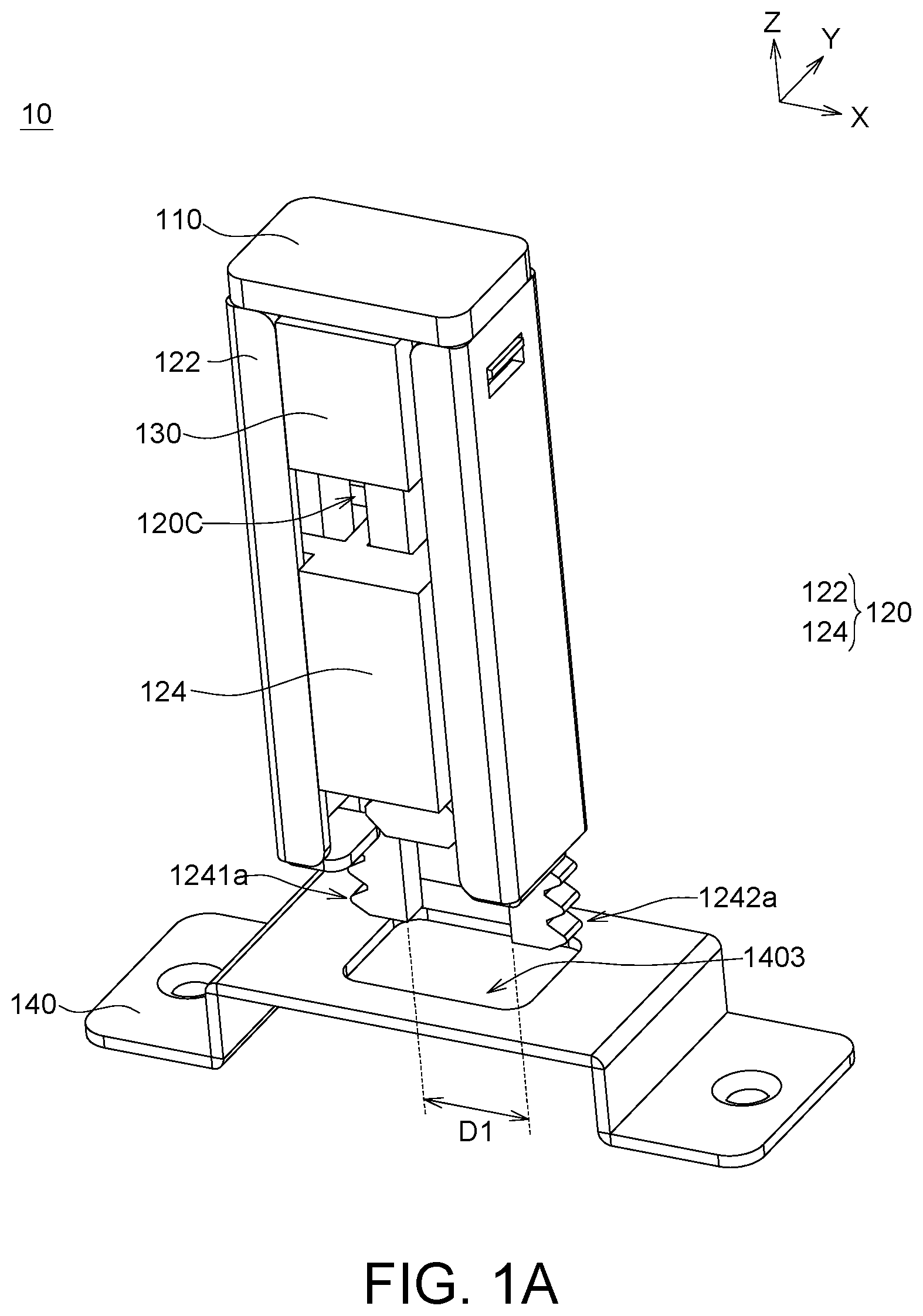
A is a front view of a fixing device according to an embodiment of the present invention.
B is a rear view of a fixing device according to an embodiment of the present invention (the first limiting member is represented by dotted lines).
C is an explosion diagram of a fixing device 10 according to an embodiment of the present invention.
D is a schematic diagram of a first limiting member according to an embodiment of the present invention.
E is a schematic diagram of a second limiting member according to an embodiment of the present invention.
F is a schematic diagram of a movement portion according to an embodiment of the present invention.
A ˜ 3 C are schematic diagrams of a fixing device engaged with a counter member according to an embodiment of the present invention.
A is a front view of a fixing device according to an embodiment of the present invention.
B is an explosion diagram of a fixing device according to an embodiment of the present invention.
C is a left side view of a first limiting member according to an embodiment of the present invention.
D is a right side view of a first limiting member according to an embodiment of the present invention.
E is a rear view of a first limiting member according to an embodiment of the present invention.
F is a schematic diagram of a second limiting member according to an embodiment of the present invention.
A ˜ 5 B are schematic diagrams of a fixing device engaged with a counter member according to an embodiment of the present invention.
A is a front view of a fixing device according to an embodiment of the present invention.
B is an explosion diagram of a fixing device according to an embodiment of the present invention.
A ˜ 7 D are schematic diagrams of a fixing device engaged with a counter member according to an embodiment of the present invention.
A ˜ 8 C are rear views of a fixing device engaged with a counter member (omitting the second limiting member) according to an embodiment of the present invention.
A ˜ 9 D are different forms of positioning groove.
DETAILED DESCRIPTION OF THE INVENTION
Detailed descriptions of the invention are disclosed below with a number of embodiments. However, the disclosed embodiments are for explanatory and exemplary purposes only, not for limiting the scope of protection of the invention. Similar/identical designations are used to indicate similar/identical elements.
The principles of the structure and operation of the present invention are disclosed below with accompanying drawings.
A is a front view of a fixing device 10 according to an embodiment of the present invention. B is a rear view of a fixing device 10 according to an embodiment of the present invention (the first limiting member 122 is represented by dotted lines). is an explosion diagram of a fixing device 10 according to an embodiment of the present invention. D is a schematic diagram of a first limiting member 122 according to an embodiment of the present invention. E is a schematic diagram of a second limiting member 124 according to an embodiment of the present invention. F is a schematic diagram of a movement portion 130 according to an embodiment of the present invention. A ˜ 3 C are schematic diagrams of a fixing device 10 engaged with a counter member 140 according to an embodiment of the present invention.
Referring to A ˜ 1 C, the fixing device 10 includes an upper cover 110 , a limiting structure 120 and a movement portion 130 . The limiting structure 120 is extended along a first direction (Z direction) and has an accommodation space 120 C and at least one pair of hooks ( 1241 a and 1242 a , 1241 b and 1242 b ; 1241 c and 1242 c ). The hooks ( 1241 a and 1242 a ; 1241 b and 1242 b ; 1241 c and 1242 c ) are engaged with a counter member 140 . The quantity of pairs of hooks is exemplified by three in the present embodiment, but the present invention is not limited thereto, and the quantity of the hooks can be adjusted to fit actual needs. Furthermore, the limiting structure 120 includes a first limiting member 122 and a second limiting member 124 . In some embodiments, the upper cover 110 , the limiting structure 120 (including the first limiting member 122 and the second limiting member 124 ) and the movement portion 130 can be formed of plastics, reinforced plastics or other suitable materials.
Refer to A ˜ 1 D. The first limiting member 122 such as a sleeve-shaped housing structure, includes an upper end opening 122 u , a lower end opening 122 n and a front side opening 122 f . The lower end opening 122 n is opposite to the upper end opening 122 u . The front side opening 122 f , which is interconnected with the upper end opening 122 u , the lower end opening 122 n and the accommodation space 120 C, exposes a part of the second limiting member 124 and the movement portion 130 . The first limiting member 122 further includes two blocking pieces 122 a and 122 b , which correspond to the lower end opening 122 n (for example, the two blocking pieces 122 a and 122 b are disposed on two opposite sides of the lower end opening 122 n ) and are extended to the inside of the first limiting member 122 in a direction parallel to the second direction (such as X direction), to position the second limiting member 124 (details are disclosed below). In some embodiments, the upper cover 110 corresponds to the upper end opening 122 u . After the second limiting member 124 and the movement portion 130 are sequentially assembled to the first limiting member 122 , the upper cover 110 can then be assembled to the first limiting member 122 . Two opposite sides of the upper cover 110 respectively have a fixing mechanism 112 and the two sides of the first limiting member 122 respectively have a side through hole 1223 in which the fixing mechanism 112 is engaged.
Referring to A ˜ 1 C and E , the second limiting member 124 includes a body portion 124 d , two extending portions 1241 and 1242 , two side grooves 124 p 1 and 124 p 2 and a rear end groove 124 p 3 . The extending portions 1241 and 1242 are connected to the body portion 124 d . The hooks (such as 1241 a and 1242 a , 1241 b and 1242 b ; 1241 c and 1242 c ) are disposed at a terminal end of the lower part of the limiting structure 120 . That is, the hooks (such as 1241 a and 1242 a ; 1241 b and 1242 b ; 1241 c and 1242 c ) are formed at the bottoms of the extending portions 1241 and 1242 and are adjacent to the counter member 140 and are engaged with the counter member 140 (details are disclosed below). For example, the extending directions of each pair of hooks (such as 1241 a and 1242 a , 1241 b and 1242 b ; 1241 c and 1242 c ) are opposite to each other and are parallel to a second direction (such as X direction) perpendicular to the first direction. In some embodiments, the width between the tips of each pair of hooks (such as 1241 a and 1242 a ; 1241 b and 1242 b ; 1241 c and 1242 c ) in the second direction can be greater than the width of the body portion 124 d of the second limiting member 124 in the second direction. The side grooves 124 p 1 and 124 p 2 are disposed on two opposite sides of the body portion 124 d . The rear end groove 124 p 3 is disposed between the side grooves 124 p 1 and 124 p 2 , and the side grooves 124 p 1 and 124 p 2 may be separated from each other. Notches 124 t may be formed in the side grooves 124 p 1 and 124 p 2 to accommodate the side fixing members 1341 and 1342 of the movement portion 130 (details are disclosed below).
Referring to A ˜ 1 C and F , the movement portion 130 includes a core portion 130 d , two side fixing members 1341 and 1342 and a middle fixing member 132 . The side fixing members 1341 and 1342 are connected to the core portion 130 d . The latch structures 1341 a and 1342 a are formed at the terminal ends of the side fixing members 1341 and 1342 , respectively. The middle fixing member 132 is connected to the core portion 130 d and is disposed between the side fixing members 1341 and 1342 . The middle fixing member 132 includes a rod portion 1321 and is connected to an expanded portion 1322 of the rod portion 1321 , wherein the width W 1322 of the expanded portion 1322 in the second direction is greater than the width W 1321 of the rod portion 1321 in the second direction. In some embodiments, the width of the expanded portion 1322 in a third direction (such as Y direction) is greater than the width of the rod portion 1321 in the third direction (not illustrated), wherein the third direction is perpendicular to the first direction and the second direction to implement dual-axis (that is, X axis and Y axis) fixing. In some embodiments, the cross-section of the expanded portion 1322 (such as the cross-section parallel to the plane formed by the second direction and the third direction) can be a circle (not illustrated) and the diameter of the circular cross-section of the expanded portion 1322 can be greater than the width of the rod portion 1321 in the third direction or the second direction to implement multi-axis fixing. In some embodiments, the movement portion 130 is disposed in the accommodation space 120 C, and at least one portion of the movement portion 130 is disposed between the first limiting member 122 and the second limiting member 124 , wherein the movement portion 130 can move relative to the limiting structure 120 . For example, the movement portion 130 can move along a direction parallel to the first direction. After the movement portion 130 is assembled to the second limiting member 124 , the core portion 130 d of the movement portion 130 is closer to the upper end opening 122 u than the body portion 124 d of the second limiting member 124 , and the rod portion 1321 of the movement portion 130 passes through the rear end groove 124 p 3 of the second limiting member 124 . The side grooves 124 p 1 and 124 p 2 of the second limiting member 124 are configured to accommodate the side fixing members 1341 and 1342 of the movement portion 130 respectively and are engaged with the notches 124 t through the latch structures 1341 a and 1342 a to fix the second limiting member 124 and the movement portion 130 . Several notches 124 t are formed on the side grooves 124 p 1 and 124 p 2 respectively, and when the movement portion 130 is pushed, the distance between the movement portion 130 and the counter member 140 can be adjusted according to the positions of the notches 124 t.
In some embodiments, the counter member 140 has a top through hole 1403 , and as the bottoms of the movement portion 130 and the second limiting member 124 pass through the top through hole 1403 , the hooks (such as 1241 a and 1242 a ; 1241 b and 1242 b ; 1241 c and 1242 c ) of the second limiting member 124 are engaged with the counter member 140 . As indicated in A- 1 B , when the core portion 130 d of the movement portion 130 is adjacent to the upper end opening 122 u of the first limiting member 122 and a bottom (such as the expanded portion 1322 ) of the movement portion 130 is disposed on the hooks (such as 1241 a and 1242 a ; 1241 b and 1242 b ; 1241 c and 1242 c ) (for example, the bottom corresponds to the first limiting member 122 ), a first distance D 1 is formed between the hooks (such as 1241 a and 1242 a ; 1241 b and 1242 b ; 1241 c and 1242 c ) in the second direction. Meanwhile, since the hooks (such as 1241 a and 1242 a ; 1241 b and 1242 b ; 1241 c and 1242 c ) have not yet passed through the top through hole 1403 of the counter member 140 , the first distance D 1 between the hooks (such as 1241 a and 1242 a ; 1241 b and 1242 b ; 1241 c and 1242 c ) in the second direction can be adjusted by an external force parallel to the second direction (for example, the first distance D 1 may be contracted or expanded by the external force). In the specification, the first distance D 1 refers to the distance which is not affected by an external force parallel to the second direction.
The movement portion 130 can move relative to the first limiting member 122 or the counter member 140 . For example, the fixing device 10 can approach the counter member 140 and drive the hooks (such as 1241 a and 1242 a ; 1241 b and 1242 b ; 1241 c and 1242 c ) of the second limiting member 124 to correspond to the top through hole 1403 of the counter member 140 as indicated in A ˜ 1 B. Then, the movement portion 130 is moved towards the counter member 140 (such as downwards) and drives the second limiting member 124 to move towards the counter member 140 , such that a portion of the hooks (such as 1241 a and 1242 a , 1241 b and 1242 b ) can pass through the top through hole 1403 as indicated in A ˜ 2 B. Afterwards, the movement portion 130 is further be moved towards the counter member 140 (such as downwards), the blocking pieces 122 a and 122 b position the second limiting member 124 , and the two sides of the expanded portion 1322 disposed at the bottom of the movement portion 130 may abut on the extending portions 1241 and 1242 to provide a supporting force parallel to the second direction (such as X direction), such that the hooks (such as 1241 a and 1242 a ) can be firmly engaged with the counter member 140 and will not come off easily as indicated in A ˜ 3 C. When the bottom of (such as the expanded portion 1322 ) of the movement portion 130 overlaps the hooks (such as 1241 a and 1242 a ; 1241 b and 1242 b ; 1241 c and 1242 c ) in the second direction (such as X direction), a second distance D 2 is formed between the hooks (such as 1241 a and 1242 a , 1241 b and 1242 b ; 1241 c and 1242 c ) in the second direction (such as X direction), wherein the second distance D 2 can be greater than the first distance D 1 . That is, the expanded portion 1322 can abut on the hooks (such as 1241 a and 1242 a , 1241 b and 1242 b ; 1241 c and 1242 c ) to increase the distance between the hooks (such as 1241 a and 1242 a , 1241 b and 1242 b ; 1241 c and 1242 c ).
In some embodiments, the back of the first limiting member 122 , such as a planar housing, is fixed on a first plate structure PL 1 , and the bottom of the counter member 140 is fixed on a second plate structure PL 2 as indicated in A . When the movement portion 130 pushes the second limiting member 124 downwards and passes through the expanded portion 1322 , the hooks (such as 1241 a and 1242 a ; 1241 b and 1242 b ; 1241 c and 1242 c ) are firmly engaged with the counter member 140 , and the first plate structure PL 1 and the second plate structure PL 2 are mutually fixed together, wherein the first plate structure PL 1 is perpendicular to the second plate structure PL 2 .
In the present embodiment, both the cross-section (such as the plane formed by X direction and Y direction) of the fixing device 10 (including an upper cover 110 , a limiting structure 120 and a movement portion 130 ) and the cross-section of the top through hole 1403 are rectangular, but the present invention is not limited thereto. In other embodiments, both the cross-section of the fixing device 10 and the cross-section of the top through hole 1403 can be a circle, a square, a triangle or a polygon.
A is a front view of a fixing device 20 according to an embodiment of the present invention. B is an explosion diagram of a fixing device 20 according to an embodiment of the present invention. C is a left side view of a first limiting member 222 according to an embodiment of the present invention. D is a right side view of a first limiting member 222 according to an embodiment of the present invention. E is a rear view of a first limiting member 222 according to an embodiment of the present invention. F is a schematic diagram of a second limiting member 224 according to an embodiment of the present invention. A ˜ 5 B are schematic diagrams of a fixing device 20 engaged with a counter member 240 according to an embodiment of the present invention.
Referring to A ˜ 4 B, the fixing device 20 includes a limiting structure 220 and a movement portion 230 . The limiting structure 220 is extended along a first direction (such as Z direction) and has an accommodation space 220 C and at least one pair of hooks 2221 a and 2222 a . The hooks 2221 a and 2222 a are engaged with a counter member 240 . Furthermore, the limiting structure 220 includes a first limiting member 222 and a second limiting member 224 . In some embodiments, the limiting structure 220 (including a first limiting member 222 and a second limiting member 224 ) and the movement portion 230 can be formed of plastics, reinforced plastics or other suitable materials.
Referring to A ˜ 4 E, the first limiting member 222 can be realized by, for example, a sleeve-shaped housing structure. The first limiting member 222 includes an upper end opening 222 u , a lower end opening 222 n and a rear side opening 222 b . The lower end opening 222 n is opposite to the upper end opening 222 u . The rear side opening 222 b is interconnected with the upper end opening 222 u , the lower end opening 222 n and the accommodation space 220 C. The first limiting member 222 includes a main portion 222 d and is connected to a first structure 2221 and a second structure 2222 of the main portion 222 d . The lower portion of the limiting structure 220 corresponds to the lower portion of the first limiting member 222 and includes a first structure 2221 and a second structure 2222 . The first structure 2221 and the second structure 2222 correspond to the lower end opening 222 n , and a gap GP 1 is formed between the first structure 2221 and the second structure 2222 . In an embodiment, the size of the gap GP 1 in the second direction (such as X direction) can be adjusted by applying an external force to the first structure 2221 and the second structure 2222 . A pair of hooks 2221 a and 2222 a can be formed on the bottom of the first limiting member 222 (that is, the bottoms of the first structure 2221 and the second structure 2222 ). For example, the bottoms of the first structure 2221 and the second structure 2222 are extended in opposite directions parallel to the second direction to form the hooks 2221 a and 2222 a.
A positioning groove 222 r , formed at the upper portion of the first limiting member 222 and interconnected with the upper end opening 222 u , has an S-shaped appearance and is configured to accommodate the protruded portion 2303 of the movement portion 230 (details are disclosed below) to position the movement portion 230 . Different portions of the positioning groove 222 r have different widths in the second direction (such as X direction). For example, the positioning groove 222 r includes several interlaced first portions and second portions. The width WI of the first portion of the positioning groove 222 r in the second direction can be equal to or greater than the width of the protruded portion 2303 in the second direction; the width WII of the second portion of the positioning groove 222 r in the second direction can be smaller than the width of the protruded portion 2303 in the second direction. In the present embodiment, the first limiting member 222 further includes two slits 222 v 1 and 222 v 2 adjacent to the positioning groove 222 r (as indicated in B ). The slits 222 v 1 and 222 v 2 have an S-shaped appearance. However, the present invention is not limited thereto, and the quantity of slits can be 1 or greater than 2, and the appearance of the slits 222 v 1 and 222 v 2 can be designed to fit actual needs. For example, the slits 222 v 1 and 222 v 2 are disposed on two opposite sides of the positioning groove 222 r to provide space and flexibility to the augmentation of the positioning groove 222 r . Several side through holes 222 v are formed on two sides of the first limiting member 222 ( C ) and are mutually fixed with the second limiting member 224 (details are disclosed below). In some embodiments, the main portion 222 d of the first limiting member 222 can be connected to the locking portions 222 x fixed on a plate structure (not illustrated) parallel to the first direction and the second direction. In the present embodiment, the locking portions 222 x have a quantity of 2 and are separated in the second direction. However, the present invention is not limited thereto, and the locking portions 222 x can have a quantity greater than 2 and can be overlapped in the second direction.
Referring to A ˜ 4 C and F , the second limiting member 224 includes an upper end hole 224 u , a lower end hole 224 n , a front side opening 224 f , a rear side housing 2242 , a plurality of side housings 2244 and a plurality of fixing mechanisms 2246 . The lower end hole 224 n is opposite to the upper end hole 224 u . The front side opening 224 f is interconnected with the upper end hole 224 u . The side housings 2244 are connected to the rear side housing 2242 . The fixing mechanisms 2246 are connected to the rear side housing 2242 , wherein the fixing mechanisms 2246 and the side housings 2244 are stacked in the first direction, and a gap GP 2 is formed between the fixing mechanism 2246 and the side housing 2244 (for example, both the top and the bottom of the fixing mechanism 2246 are separated from the side housing 2244 ) to provide a larger space to the fixing mechanisms 2246 . The side through holes 222 v of the first limiting member 222 correspond to the fixing mechanisms 2246 , and as the fixing mechanisms 2246 respectively are engaged with the side through holes 222 v of the first limiting member 222 , the first limiting member 222 and the second limiting member 224 are assembled and mutually fixed and together surround the accommodation space 220 C. In the present embodiment, the fixing mechanisms 2246 have a quantity of 6, the side through holes 222 v have a quantity of 6, and the fixing mechanisms 2246 and the side through holes 222 v are arranged in a symmetric manner, but the present invention is not limited thereto. In other embodiments, the fixing mechanisms 2246 can have a quantity of 2 or greater than 2, the side through holes 222 v can have a quantity of 2 or greater than 2, and the fixing mechanisms 2246 and the side through holes 222 v do not need to be arranged in a symmetric manner.
The movement portion 230 includes an expanded portion 2301 , a rod portion 2302 and a protruded portion 2303 . The rod portion 2302 is connected to the expanded portion 2301 and passes through the accommodation space 220 C along the first direction. The width W 2301 of the expanded portion 2301 in the second direction is greater than the width W 2302 of the rod portion 2302 in the second direction and is greater than the width W 222 of the main portion 222 d of the first limiting member 222 in the second direction. In the present embodiment, the expanded portion 2301 has a cap appearance. However, the present invention is not limited thereto, and the expanded portion 2301 can have a disc shape or other suitable shape for the user to conveniently apply a force to the movement portion 230 . The protruded portion 2303 is disposed on the rod portion 2302 , such as protruded forward (or outward) from the rod portion 2302 . The protruded portion 2303 corresponds to the positioning groove 222 r . As the protruded portion 2303 and the positioning groove 222 r are mutually engaged, the movement portion 230 and the first limiting member 222 are mutually fixed.
In some embodiments, a top through hole 2403 is formed on the counter member 240 , and as the bottoms of the movement portion 230 and the first limiting member 222 can pass through the top through hole 2403 , the hooks 2221 a and 2222 a of the first limiting member 222 are engaged with the counter member 240 .
The movement portion 230 can move relative to the limiting structure 220 (includes the first limiting member 222 and the second limiting member 224 ) or the counter member 240 . When the bottom of the movement portion 230 abuts on the hooks 2221 a and 2222 a , a first distance D 3 is formed between the hooks 2221 a and 2222 a as indicated in A . Meanwhile, the expanded portion 2301 is separated from the second limiting portion 224 , the protruded portion 2303 is engaged at the first position of the positioning groove 222 r , the bottom of the first limiting member 222 (that is, the bottoms of the first structure 2221 and the second structure 2222 ) passes through the top through hole 2403 . Then, the movement portion 230 is moved towards the counter member 240 (such as downwards), the two sides of the rod portion 2302 of the movement portion 230 abut on the first structure 2221 and the second structure 2222 to provide a supporting force parallel to the second direction (such as X direction) for enabling the hooks 2221 a and 2222 a to be firmly engaged with the counter member 240 and not to come off easily as indicated in B . When the bottom of the movement portion 230 overlaps the hooks 2221 a and 2222 a in the second direction (the rod portion 2302 of the movement portion 230 also passes through the top through hole 2403 ), a second distance D 4 is formed between the hooks 2221 a and 2222 a , wherein the second distance D 4 is greater than the first distance D 3 . Meanwhile, the expanded portion 2301 contacts the second limiting portion 224 (the present invention is not limited thereto), the protruded portion 2303 is engaged at the second position of the positioning groove 222 r , and the second position at which the protruded portion 2303 is disposed is farther away from the upper end opening 222 u than the first position.
In some embodiments, the back of the first limiting member 222 , such as a planar housing, is fixed on a first plate structure (not illustrated), and the bottom of the counter member 240 is fixed on a second plate structure (not illustrated). When the movement portion 230 is moved downwards, the hooks 2221 a and 2222 a are firmly engaged with the counter member 240 and the first plate structure and the second plate structure are mutually fixed, wherein the first plate structure is perpendicular to the second plate structure.
In the present embodiment, the cross-section of the limiting structure 220 (such as the plane formed by X direction and Y direction) is similar to a semi-circle, and the cross-section of the top through hole 2403 is a circle, but the present invention is not limited thereto. In other embodiments, the cross-section of the limiting structure 220 can be a circle, a square, a triangle or a polygon. The cross-section of the top through hole 2403 can be a square, a triangle or a polygon. The shape of the cross-section of the limiting structure 220 corresponds to the shape of the cross-section of the top through hole 2403 .
A is a front view of a fixing device 30 according to an embodiment of the present invention. B is an explosion diagram of a fixing device 30 according to an embodiment of the present invention. A ˜ 7 D are schematic diagrams of a fixing device 30 engaged with a counter member 340 according to an embodiment of the present invention. A˜ 7 B are front views of a fixing device 30 engaged with a counter member 340 . C is a left side view of a fixing device 30 engaged with a counter member 340 . D is a rear view of a fixing device 30 engaged with a counter member 340 . A ˜ 8 C are rear views of a fixing device 30 engaged with a counter member 340 (omitting the second limiting member 324 ) according to an embodiment of the present invention. A ˜ 9 D are different forms of positioning groove 322 r.
Referring to A ˜ 6 B, the fixing device 30 includes a limiting structure 320 , a movement portion 330 and a spring structure 350 . The limiting structure 320 is extended along a first direction (such as Z direction) and has an accommodation space 320 C and at least one pair of hooks 3221 a and 3222 a . The hooks 3221 a and 3222 a are engaged with a counter member 340 . Furthermore, the limiting structure 320 includes a first limiting member 322 and a second limiting member 324 . In some embodiments, the limiting structure 320 (including the first limiting member 322 and the second limiting member 324 ) and the movement portion 330 can be formed of plastics, reinforced plastics or other suitable materials.
The first limiting member 322 , which can be a sleeve-shaped housing structure, includes an upper end opening 322 u , a lower end opening 322 n and a rear side opening 322 b (illustrated in C ). The lower end opening 322 n is opposite to the upper end opening 322 u . The rear side opening 322 b is interconnected with the upper end opening 322 u , the lower end opening 322 n and the accommodation space 320 C. The first limiting member 322 includes a main portion 322 d and is connected to a first structure 3221 and a second structure 3222 of the main portion 322 d . The lower portion of the limiting structure 320 corresponds to the lower portion of the first limiting member 322 and includes a first structure 3221 and a second structure 3222 , wherein the first structure 3221 and the second structure 3222 correspond to the lower end opening 322 n , and a gap GP 3 is formed between the first structure 3221 and the second structure 3222 . In an embodiment, the size of the gap GP 3 in the second direction (such as the X direction) can be adjusted by applying an external force to the first structure 3221 and the second structure 3222 . A pair of hooks 3221 a and 3222 a are formed on the bottom of the first limiting member 322 (that is, the bottoms of the first structure 3221 and the second structure 3222 ). For example, the bottoms of the first structure 3221 and the second structure 3222 are extended in opposite directions parallel to the second direction to form the hooks 3221 a and 3222 a.
A positioning groove 322 r , formed on the first limiting member 322 and adjacent to the upper end opening 322 u , is configured to accommodate the protruded portion 3303 of the movement portion 330 (details are disclosed below) to position the movement portion 330 . The protruded portion 3303 of the movement portion 330 can move freely in the positioning groove 322 r . Referring to A ˜ 9 C, in some embodiments, the positioning groove 322 r includes a first portion P 1 , a second portion P 2 and a third portion P 3 , P 3 ′ or P 3 ″, and the extending direction of the first portion P 1 is different from the extending direction of the second portion P 2 , and the extending direction of the third portion P 3 , P 3 ′ or P 3 ″ is intersected with the extending direction of the second portion P 2 . The extending direction of the first portion P 1 of the positioning groove 322 r is parallel to the extending direction of the third portion P 3 as indicated in A . The extending direction of the first portion P 1 of the positioning groove 322 r is intersected with the extending direction of the third portion P 3 ′ or P 3 ″ as indicated in B ˜ 9 C. In some embodiments as indicated in D , the positioning groove 322 r includes a first portion P 1 and a second portion P 2 ′, but does not have a third portion, wherein the length of the second portion P 2 ′ can be greater than the length of the second portion P 2 . The third portion P 3 ′ or P 3 ″ and the extended second portion P 2 ′ are configured to avoid the protruded portion 3303 coming off the positioning groove 322 r and make the movement portion 330 more firmly positioned. However, the positioning groove 322 r of the present invention is not limited to the above exemplifications and any shape of the positioning groove 322 r which avoids the protruded portion 3303 coming off the positioning groove 322 r can be included in the present application.
As indicated in A ˜ 7 D, several side through holes 322 v are formed on the two sides of the first limiting member 322 and are mutually fixed with the second limiting member 324 (details are disclosed below). In some embodiments, the main portion 322 d of the first limiting member 322 can be connected to the locking portions 322 x fixed on a plate structure (not illustrated). In the present embodiment, the locking portions 322 x have a quantity of 2 and are separated in the second direction. However, the present invention is not limited thereto, and the locking portions 322 x can have a quantity greater than 2 and can be overlapped in the second direction.
The second limiting member 324 includes an upper end hole 324 u , a lower end hole 324 n , a front side opening 324 f , a rear side housing 3242 (as indicated in B ), a plurality of side housings 3244 and a plurality of fixing mechanisms 3246 . The lower end hole 324 n is opposite to the upper end hole 324 u . The front side opening 324 f is interconnected with the upper end hole 324 u . The side housings 3244 are connected to the rear side housing 3242 . The fixing mechanisms 3246 are connected to the rear side housing 3242 , wherein the fixing mechanisms 3246 and the side housings 3244 are stacked in the first direction, and a gap GP 4 is formed between the fixing mechanism 3246 and the side housing 3244 (for example, both the top and the bottom of the fixing mechanism 3246 are separated from the side housings 3244 ) to provide a larger space to the fixing mechanisms 3246 . The side through holes 322 v of the first limiting member 322 (illustrated in C ) correspond to the fixing mechanisms 3246 , and as the fixing mechanisms 3246 respectively are engaged with the side through holes 322 v of the first limiting member 322 , the first limiting member 322 and the second limiting member 324 are assembled and mutually fixed, and the first limiting member 322 and the second limiting member 324 together surround the accommodation space 320 C. In the present embodiment, the fixing mechanisms 3246 have a quantity of 6, the side through holes 322 v have a quantity of 6 and the fixing mechanisms 3246 , and the side through holes 322 v are symmetric in a left and right manner, but the present invention is not limited thereto. In other embodiments, the fixing mechanisms 3246 can have a quantity of 2 or greater than 2, the side through holes 322 v can have a quantity of 2 or greater than 2 and the fixing mechanisms 3246 , and the side through holes 322 v do not need to be arranged in a symmetric manner.
The movement portion 330 includes an expanded portion 3301 , a rod portion 3302 and a protruded portion 3303 . The rod portion 3302 is connected to the expanded portion 3301 and passes through the accommodation space 320 C along the first direction. The width W 3301 of the expanded portion 3301 in the second direction is greater than the width W 3302 of the rod portion 3302 in the second direction and is greater than the width W 322 of the main portion 322 d of the first limiting member 322 in the second direction. In the present embodiment, the expanded portion 3301 has a cap appearance. However, the present invention is not limited thereto, and the expanded portion 3301 can have a disc shape or other suitable shape for the user to conveniently apply a force to the movement portion 330 . The protruded portion 3303 is disposed on the rod portion 3302 , such as protruded forward (or outward) from the rod portion 3302 . The protruded portion 3303 corresponds to the positioning groove 322 r . As the protruded portion 3303 and the positioning groove 322 r are mutually engaged, the movement portion 330 and the first limiting member 322 are mutually fixed.
The spring structure 350 , disposed in the accommodation space 320 C and under the protruded portion 3303 , surrounds the rod portion 3302 and enables the movement portion 320 to perform reciprocal movement along an axis parallel to the first direction.
In some embodiments, the counter member 340 has a top through hole 3403 , and as the bottoms of the movement portion 330 and the first limiting member 322 may pass through the top through hole 3403 , the hooks 3221 a and 3222 a of the first limiting member 322 are engaged with the counter member 340 .
The movement portion 330 can move relative to the limiting structure 320 (including the first limiting member 322 and the second limiting member 324 ) or the counter member 340 . When the bottom of the movement portion 330 is disposed above the hooks 3221 a and 3222 a , a first distance D 5 is formed between the hooks 3221 a and 3222 a as indicated in A . Meanwhile, the expanded portion 3301 is separated from the second limiting portion 324 , the protruded portion 3303 is disposed at the first position LA 1 of the positioning groove 322 r , the bottom of the first limiting member 322 (that is, the bottoms of the first structure 3221 and the second structure 3222 ) may pass through the top through hole 3403 . The state of the spring structure 350 of A is illustrated in A . As indicated in A , the spring structure 350 is not compressed and has a first height H 1 in the first direction. Then, the movement portion 330 is moved towards the counter member 340 (such as downwards) and the two sides of the rod portion 3302 of the movement portion 330 abut on the first structure 3221 and the second structure 3222 . Meanwhile, when the bottom of the movement portion 330 overlaps with the hooks 3221 a and 3222 a in the second direction (the rod portion 3302 of the movement portion 330 also passes through the top through hole 3403 ), a second distance D 6 is formed between the hooks 3221 a and 3222 a as indicated in B , wherein the second distance D 6 is greater than the first distance D 5 . Meanwhile, the expanded portion 3301 contacts the second limiting portion 324 (the present invention is not limited thereto), the protruded portion 3303 is engaged at the second position LA 2 of the positioning groove 322 r , and the second position LA 2 at which the protruded portion 3303 is disposed is farther away from the upper end opening 322 u than the first position LA 1 . The state of the spring structure 350 of B is illustrated in B . As indicated in B , the spring structure 350 is compressed and has a second height H 2 in the first direction. Then, as the movement portion 330 is rotated and drives the protruded portion 3303 to slide along the second portion P 2 in accordance with the shape of the positioning groove 322 r and rebound upwards to the third portion P 3 , the protruded portion 3303 is engaged at the third position LA 3 as indicated in C ˜ 7 D. The third position LA 3 at which the protruded portion 3303 is disposed is closer to the upper end opening 322 u than the second position LA 2 . The state of the spring structure 350 of C ˜ 7 D is illustrated in C . As indicated in C , the spring structure 350 slightly rebounds and has a third height H 3 in the first direction. The third height H 3 of the spring structure 350 is greater than the second height H 2 and is smaller than the first height H 1 . As indicated in C ˜ 7 D and C , the bottom of the rod portion 3302 provides a supporting force parallel to the second direction (such as the X direction) for enabling the hooks 3221 a and 3222 a to be firmly engaged with the counter member 340 and not to come off easily. When the bottom of the movement portion 330 overlaps the hooks 3221 a and 3222 a in the second direction (the rod portion 3302 of the movement portion 330 passes through the top through hole 3403 ), the second distance D 6 is maintained between the hooks 3221 a and 3222 a . Meanwhile, the expanded portion 3301 contacts the second limiting portion 324 (the present invention is not limited thereto).
In some embodiments, the back of the first limiting member 322 , such as a planar housing, is fixed on a first plate structure (not illustrated), and the bottom of the counter member 340 is fixed on a second plate structure (not illustrated). When the movement portion 330 is moved downwards, the hooks 3221 a and 3222 a are firmly engaged with the counter member 340 , and the first plate structure and the second plate structure are mutually fixed, wherein the first plate structure is perpendicular to the second plate structure.
In the present embodiment, the cross-section of the limiting structure 320 (such as the plane formed by X direction and Y direction) is similar to a semi-circle, and the cross-section of the top through hole 3403 is a circle, but the present invention is not limited thereto. In other embodiments, the cross-section of the limiting structure 320 can be a circle, a square, a triangle or a polygon. The cross-section of the top through hole 3403 can be a square, a triangle or a polygon.
According to an embodiment of the present invention, a fixing device is provided. The fixing device includes a limiting structure and a movement portion. The limiting structure is extended along a first direction and has an accommodation space and at least one pair of hooks disposed at a terminal end of the limiting structure. The extending directions of the at least one pair of hooks are opposite to each other and respectively are parallel to a second direction perpendicular to the first direction. The movement portion is disposed in the accommodation space and moves relative to the limiting structure. When a bottom of the movement portion is disposed above the at least one pair of hooks, a first distance is formed between the at least one pair of hooks in the second direction. When the bottom of the movement portion overlaps the at least one pair of hooks in the second direction, a second distance greater than the first distance is formed between the at least one pair of hooks in the second direction.
The fixing device of the present invention includes a limiting structure and a movement portion. A pair of hooks are formed at the terminal end of the limiting structure. When the movement portion moves relative to the limiting structure, the distance between the hooks can be adjusted through the movement portion, such that the two plate structures connected to the fixing device can be easily separated from each other or can be mutually fixed without using several screws or plugs.
While the invention has been described by way of example and in terms of the preferred embodiment (s), it is to be understood that the invention is not limited thereto. On the contrary, it is intended to cover various modifications and similar arrangements and procedures, and the scope of the appended claims therefore should be accorded the broadest interpretation so as to encompass all such modifications and similar arrangements and procedures.
Figures (20)
Citations
This patent cites (51)
- US3117484
- US3233504
- US3426399
- US3728761
- US4316689
- US4537542
- US4548533
- US4934885
- US5211519
- US5387065
- US7033121
- US7549199
- US8534651
- US9217452
- US9562549
- US10260548
- US10589835
- US10836463
- US10920815
- US20040028503
- US20040049895
- US20080219758
- US20120230796
- US20120291240
- US20130084130
- US20130136559
- US20140047679
- US20140050548
- US20150263468
- US20160138628
- US20160138629
- US20160298668
- US20160333917
- US20170198738
- US20170211607
- US20170234348
- US20170268552
- US20170291558
- US20180313380
- US20190032696
- US20190048907
- US20200049186
- US20200158155
- US20200217345
- US20200290180
- US20220042530
- US20220186758
- US20220373011
- US103075399
- US105531487
- US110030246