Abstract
A spinal fixation device includes a pair of substantially s-shaped plates, each plate having an outer surface and a bone contact surface and at least one aperture therethrough. A bolt joins the plates at a desired orientation, through the aperture. The bolt includes a head with a rounded or beveled base for facilitating fixation of the plates with a spinous processes while the plates are tilted or rotated with respect to one another and the spinal column.
Claims (13)
1. A spinal fixation device comprising: a first plate with a substantially s-shape having an outer surface and a bone contact surface and a plurality of first plate apertures therethrough, a second plate with a shape substantially identical to the first plate having an outer surface and a bone contact surface and a plurality of second plate apertures therethrough such that each one of the plurality of first plate apertures has an aligned in a medial lateral direction and analogous one aperture of the plurality of second plate apertures when the first plate and second plate are aligned as mirror images; and a bolt extending in the medial-lateral direction from the bone contact surface of the first plate to the bone contact surface of the second plate for joining the first and second plates at a desired orientation through a selected aperture of the plurality of apertures, wherein in each of the plurality of first apertures and each of the plurality of second apertures are configured to receive the bolt, and wherein the bolt is configured to join the first and second plates through the selected apertures wherein the selected apertures are selected from the group of apertures consisting of: aligned and analogous apertures and non-aligned and non-analogous apertures; the bolt including a head with a rounded or beveled base for facilitating fixation of the plates with a spinous processes while the plates are tilted or rotated with respect to one another and the spinal column.
10. A spinal fixation device comprising: a first s-shaped plate, a second s-shaped plate, wherein the first s-shaped plate and the second s-shaped plate form a pair of substantially identical s-shaped plates, each of the first s-shaped plate and the second s-shaped plate having a plurality of apertures therethrough, wherein each of the plurality of apertures on the first plate has at least one analogous aperture on the second plate and at least one non-analogous aperture on the second plate; and a single bolt extending in a medial/lateral direction for joining the plates at a desired orientation, and wherein each of the plurality of apertures in the first s-shaped plate and each of the plurality of apertures in the second s-shaped plate are configured to receive the single bolt, and wherein the single bolt is operatively sized to join the first plate via any one of the plurality of apertures on the first s-shaped plate and an aperture of the plurality of apertures on the second s-shaped plate selected from the group of apertures consisting of: the at least one analogous aperture and the at least one non-analogous aperture; the single bolt including a head with a rounded or beveled base for facilitating fixation of the plates with spinous processes while the plates are tilted or rotated with respect to one another and the spinal column.
Show 11 dependent claims
2. The device of claim 1 , the plurality of apertures comprising beveled apertures.
3. The device of claim 1 , the plates comprising titanium.
4. The device of claim 1 , the plates comprising a biocompatible material having sufficient strength to fuse adjacent vertebrae of the spinal column.
5. The device of claim 1 , the bone contact surfaces of each plate comprising one or more prongs for penetrating bone of the spinous process, to enhance fixation of the plates with the spinous process.
6. The device of claim 1 , the rounded or beveled base of the bolt allowing variation in angles between the plates, when the plates are joined.
7. The device of claim 1 , further comprising a nut for joining with a free end of the bolt to secure the plates about the spinous process.
8. The device of claim 1 , the head of the bolt comprising an aperture or other surface feature for accepting a tool for tightening the bolt with the plates and an end nut.
9. The device of claim 1 , the plates configured to secure a spacer therebetween.
11. The device of claim 10 , the plurality of apertures through each plate tapering from an outer surface to a bone contact surface.
12. The device of claim 11 , further comprising a tapered nut for securing with an end of the bolt, to secure the plates together about a spinous process.
13. The device of claim 12 , the bolt head, nut and plurality of apertures configured with tolerances therebetween that permit joining of the plates, bolt and nut at a variety of angles.
Full Description
Show full text →
RELATED APPLICATIONS
This application claims priority to U.S. Provisional Patent Application No. 61/544,920, filed 7 Oct. 2011, and to U.S. Provisional Patent Application No. 61/558,736, filed 11 Nov. 2011, both of which are incorporated herein by reference.
BACKGROUND
Spinal fixation is a neurosurgical procedure in which two or more vertebrae are anchored to each other using a synthetic device. Spinal fixation is often performed to stabilize the spine or reduce vertebral mobility, and thus reduce pain, tingling in the extremities due to compression of nerves, and/or to avoid potential damage to the spinal column.
During spinal fixation surgery, bone is often shaved from spinous processes of vertebrae to be fixed, in order to provide an even surface for fixation plates or other devices. However, shaving thins the bone, thus compromising vertebral strength.
SUMMARY
The spinal fixation device described herein addresses the problem of bone loss due to spinous shaving, by providing plates that join together in plane, or with one or both of the plates tilted out of plane and/or rotated with respect to one another. The wide range of plate positions provided by the disclosed device allows a neurosurgeon to customize placement of the plates with a patient's existing bone topography, thereby reducing or eliminating the need to shave the spinous processes.
In one embodiment, a spinal fixation device includes a pair of substantially s-shaped plates, each having a plurality of apertures therethrough. A bolt having a head with a rounded or beveled base joins the plates at a desired orientation. The rounded or beveled base allows the plates to be joined while rotated or tilted with respect to one another and the spinal column.
BRIEF DESCRIPTION OF THE DRAWINGS
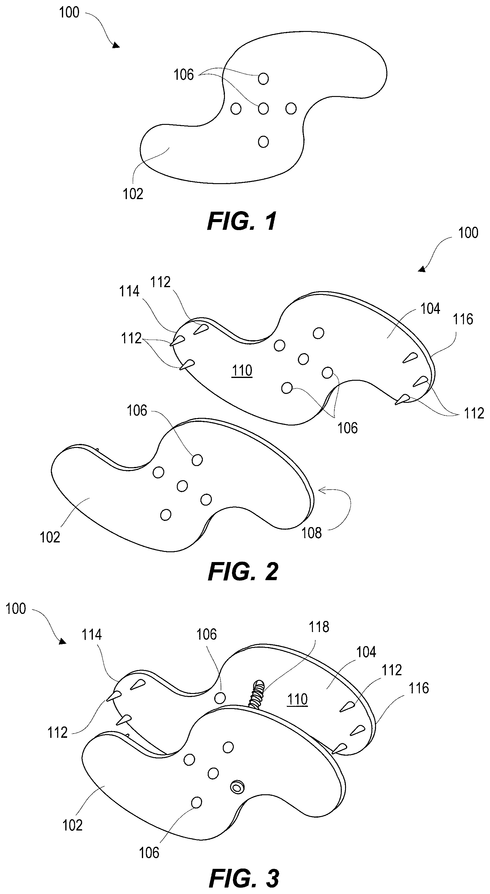
is a front view of a spinal fixation device, according to an embodiment.
is a perspective view showing dual plates of the spinal fixation device of .
is a perspective view of the device of , showing a bolt joining a hole of the front plate with a non-analogous hole of the rear plate, according to an embodiment.
is a cross-sectional view showing the plates of rotated with respect to one another and joined via a bolt through non-analogous holes of the front and rear plates, according to an embodiment.
is a cross-sectional view showing a bolt fitted with a hole of a spinal fixation device, according to an embodiment.
shows the bolt of tilted or rotated with respect to its hole.
shows the bolt of tilted or rotated with respect to its hole.
is a cross-sectional side view illustrating male and female joining members for rotatably securing a bolt with plates of a spinal fixation device, according to an embodiment.
shows a male and female connection system for securing a bolt with the spinal fixation device of , according to an embodiment.
shows the connection system and bolt of connecting plates of the spinal fixation device of , according to an embodiment.
shows the device of secured with and fusing adjacent vertebrae, according to an embodiment.
is a cross-sectional top view showing the device of secured with and fusing adjacent vertebrae, according to an embodiment.
shows three stacked spinal fixation devices, according to an embodiment.
is a front view of a spinal fixation device, according to an embodiment.
is a perspective view showing dual plates of the spinal fixation device of .
is a perspective view of the device of , showing a bolt joining a hole of the front plate with a non-analogous hole of the rear plate, according to an embodiment.
shows plates of the spinal fixation device of joined while rotated and tilted with respect to one another.
shows the spinal fixation device of secured with and fusing adjacent vertebrae, according to an embodiment.
depicts a method of vertebral fixation, according to an embodiment.
depicts another method of vertebral fixation, according to an embodiment.
is a perspective view showing the device of with an interspinous spacer, according to an embodiment.
shows the device and spacer of joined with a bolt, according to an embodiment.
is an assembly view that shows an alternative embodiment of a spinal fixation device.
is a midsectional view that shows an alternative clamping structure for use in a spinal fixation device.
DETAILED DESCRIPTION
show a spinal fixation device 100 , and are best viewed together with the following description. Device 100 includes a front plate 102 and a rear plate 104 , each having a plurality of apertures or holes 106 therethrough. Plates 102 , 104 are for example titanium, although they may be formed with other biocompatible materials having sufficient strength to fuse adjacent vertebrae. Bone-contact surfaces 108 and 110 of plates 102 and 104 , respectively, include one or more prongs 112 . As shown, three prongs 112 are positioned with opposing arms 114 , 116 of each plate. However, it will be appreciated that more or fewer prongs may be used, and that number and arrangement of prongs may differ from plate to plate (i.e., from plate 102 to plate 104 ), or from arm to arm (i.e., from arm 114 to arm 116 ). When plates 102 , 104 are placed with bone (e.g., with spinous processes), prongs 112 penetrate or bite into the bone, to enhance fixation of device 100 .
Plates 102 , 104 may be generally s-shaped to facilitate stacking and side-by-side placement of multiple devices 100 , in addition to providing opposing arms 114 , 116 for prongs 112 . See, for example, .
A bolt or screw (hereinafter, “bolt 118 ”) joins plate 102 with plate 104 . As shown in , bolt 118 includes a tapered or rounded head, allowing bolt 118 to rotate and tilt within one hole 106 . The angle of bolt 106 between plates 102 and 104 may therefore be varied such that bolt 106 may join non-analogous holes 106 of opposing plates 102 and 104 , as schematically shown in . It will be appreciated that bolt 118 may also be a set bolt, blind bolts, ziptie bolt or other bolt. Bolt 118 may be secured with plates 102 and 104 using a nut.
A male and female connection system 200 may be used with bolt 118 and device 100 . illustrate a system 200 including a ball-and-socket receiving portion 202 for accepting a bolt collar 204 . Bolt collar 204 may include internal threads 206 (depicted in dotted outline) for mating with an externally threaded screw 118 . Bolt collar 204 may also include external threads 208 for mating with internal threads 210 (also in dotted outline) of receiving portion 202 .
A spherical or semi-spherical head 212 of ball-and-socket receiving portion 202 facilitates variable placement of screw 118 with holes 106 , and may increase a range of possible angles between screw 118 and plates 102 , 104 . Head 212 may include an aperture or other surface feature (not shown) for temporarily joining with a hex key or other tool for tightening bolt 118 with system 200 . An exemplary tool for tightening bolt 118 and/or system 200 may be an electric Allen wrench having internal actuators within the long stem of the Allen wrench for turning the key tip, without having to rotate the Allen wrench about the tip when the tip is mated with bolt 118 . The electric Allen wrench may have a single long stem for mating with an electric drill, with the distal end of the stem (distal to the drill) configured to fit a variety of “key end” sizes. In one aspect, the key ends are tapered from a stem-connecting end to a narrower end for fitting with a bolt, such as bolt 118 .
schematically illustrate device 100 mounted to fuse adjacent vertebrae 302 , 304 of a spinal column 300 , shown in part. As shown, plates 102 , 104 may be rotated with respect to one another and still joined by a surgeon via bolt 118 through selected holes 106 . Although not shown here, plates 102 and 104 may also be horizontally or vertically offset from one another. Adjustable bolt angles (described above) additionally allow for securing device 100 with plates 102 and 104 to be tilted in and out of plane with respect to one another, thus providing a wide range of plate positions. In practice, a surgeon may slide, rotate and tilt one or both of plates 102 and 104 along the spinous process(es), in order to find a “best fit” with the existing bone topography. Device 100 may therefore reduce or eliminate the shaving that is necessary to align prior art fixation devices with vertebral bone, thus preserving strength of the spinous processes and reducing complications associated with bone shaving, as well as reducing overall surgical time and complexity.
Optionally, where a surgeon wishes to distract adjacent spinal processes, bolt 118 additionally secures a spacer between plates 102 and 204 . show one exemplary spacer 120 , which may be made from PEEK plastic or other suitable, biocompatible material. Width of spacer 120 is selected to securely fit a desired space between plates 102 and 104 . Diameter d of spacer 120 is selected according to the interspinous space between adjacent spinous processes. Spacer 120 width for example ranges from 4 to 10 mm, and diameter d may be between about 6 mm and 14 mm, depending upon the interspinous space and any additional decompression/distraction desired. It will be appreciated that although shown as an oval, spacer 120 may take a rounded or other geometric shape. Furthermore, although not shown here, spacer 120 may include surface features along its width (such as receiving channels) for fitting with spinous processes.
are similar to , showing a device 400 that shares features of device 100 , but has plates 402 and 404 with a squared-off shape compared to plates 102 and 104 . Like numbers represent similar elements in and corresponding . It will be appreciated that although not shown, a spacer such as spacer 120 may also be used with device 400 .
illustrates a method 500 of spinal fixation. In step 502 , opposing plates of a spinal fixation device are placed with spinous processes of adjacent vertebrae so as to maximize bone-to-plate contact. In one example of step 502 , plates 102 and 104 of device 100 (or plates 402 and 404 of device 400 ) are rotated, tilted, moved laterally or moved horizontally with respect to the vertebral column to achieve a best fit with opposite sides of adjacent spinous processes. Receiving surfaces of the spinous processes are prepared, in optional step 504 . In one example, one side of the spinous process of vertebra 302 ( ) is cleaned or otherwise prepared, but not shaved, where plate 102 may be tilted or rotated such that arm 114 lies substantially flush with existing bone. Likewise, where plate 102 / 104 may be manipulated to fit existing boney surfaces, shaving may be reduced or eliminated.
In step 506 , a surgeon selects bolt orientation and entrance and exit bolt holes of plates 102 , 104 , in order to secure device 100 at the chosen orientation. The bolt is placed through the entrance hole in a first plate, and advanced between the plates and through the exit hole in the second plate, in steps 508 and 510 . In one example, bolt 118 may be placed through hole 106 C of plate 102 and through hole 106 B of plate 104 (see ). A nut may be used to secure the bolt in place, in step 512 . The bolt is tightened to secure plates of the spinal fixation device in the desired orientation, in step 514 (for example, pressing prongs 512 into the bone).
illustrates a method 600 of spinal fixation utilizing a male and female connection system, such as system 200 . Opposing plates are placed with spinous processes of adjacent vertebrae, in step 602 , so as to maximize bone-to-plate contact. Bone surfaces are prepared as necessary in step 604 , for example as described with respect to method 500 , above. Bolt orientation and entrance and exit holes are selected in step 606 , and the bolt is advanced through the entrance hole of one plate in step 608 . A male collar of the male and female connection system is placed with the bolt, between the device plates, in step 610 . For example, collar 204 is threaded at least partially onto bolt 118 , between plates 102 and 104 . A female ball-and-collar receptacle is inserted into the exit hole, in step 612 . For example, receptacle 202 is inserted into a selected hole 106 from an outer side of plate 104 . The male collar and female receptacle are joined together, in step 614 . In one example, receptacle 202 is held in place via a hex key or other tool while collar 104 is rotated to join exterior threads of collar 104 with interior threads of receptacle 202 . Screw 118 may be further tightened to advance the screw within the collar, in step 616 . In step 618 , the spinal fixation device is secured in its desired position by further tightening the bolt and/or female receptacle.
is an assembly view that shows an alternative embodiment of a spinal fixation device 2300 . Plates 2302 , 2304 have a generally S-shaped structure for stacking of plates as described above, together with pins 2306 , 2308 for stabilizing plate to bone contact. Plate 2302 defines a central opening 2310 with opening 2312 in plate 2304 being a minor image of opening 2310 . Opening 2310 has a plurality of opposed radiused knurls 2314 - 2316 , 2318 - 2320 , 2322 - 2324 . These knurls taper centrally to narrow towards ridge 2326 which, in turn, narrows at an even sharper taper towards edge 2328 . These structures in opening 2310 complement a tapered head 2330 and collar 2332 of bolt 2334 . Nut 2336 has the same type of tapered head 2338 and collar 2340 , where the nut 2336 may be slidingly engaged for retention in a tapered channel 2342 along a bottom surface of plate 2304 . Tolerances between the bolt head 2330 and opening 2310 , as well as tolerances between nut 2336 and opening 2312 , permit the bolt 2334 and nut 2336 to joint plates 2302 , 2304 at any angle Φ. By way of example, the nature of jointing may be angled such that head 2330 resides in knurl 2322 and nut 2336 resides in knurl 2344 .
is a midsectional view that shows an alternate clamping mechanism 2400 that may be used to install plates 2402 , 2404 on spinous process (not shown). Plate 2402 is integrally formed with a central tubular wall 2406 . The wall 2406 carries a pinion gear assembly 2408 that may be turned on arc 2410 by engagement between a key (not shown) and a keyhole 2412 . A ratchet-stop 2414 selectively retains gear assembly 2408 at a position of rotation on arc 2410 . Plate 2404 is integrally formed with tubular wall 2416 , which is telescopically received within tubular wall 2406 . The wall 2416 carries a rack gear 2418 that engages the pinion gear assembly 2408 such that clockwise rotation of the pinion gear assembly 2408 on arc 2410 moves plates 2402 , 2404 together, reducing distance D. Wall 2416 is provided with a slot for accommodating the pinion gear assembly 2408 . As is a midsectional view, the slot is not visible; however, exemplary position of the slot along a floor of tubular wall 2416 is indicated by a space 2420 . It will be appreciated that the slot may be positioned within wall 2416 at a location other than space 2420 . An opposing slot (not shown) in wall 2416 provides access to the keyhole 2412 . Tolerances between the walls 2406 , 2416 may permit the joining of plates 2402 , 2404 in a relationship that is not necessary in parallel where, for example, plate 2404 may be tilted and an angle α relative to plate 2402 .
While the present invention has been described above, it should be clear that many changes and modifications may be made to the process and product without departing from the spirit and scope of this invention.
Figures (13)
Citations
This patent cites (686)
- US765879
- US832201
- US1137585
- US1331737
- US1400648
- US1725670
- US1737488
- US2137121
- US2677369
- US2689568
- US2774350
- US2789860
- US3025853
- US3039468
- US3242922
- US3409013
- US3628535
- US3648691
- US3788318
- US3789852
- US4092788
- US4269178
- US4274401
- US4369769
- US4369770
- US4409968
- US4448191
- US4554914
- US4570618
- US4573454
- US4599086
- US4636217
- US4697582
- US4773402
- US4892545
- US5007909
- US5010879
- US5011484
- US5030220
- US5062850
- US5306275
- US5390683
- US5413576
- US5472426
- US5496318
- US5503617
- US5527312
- US5540703
- US5609634
- US5609636
- US5628756
- US5645599
- US5653763
- US5658335
- US5702452
- US5702453
- US5716358
- US5725582
- US5800550
- US5813978
- US5836948
- US5860977
- US5876404
- US5928232
- US5976146
- US5989256
- US6045442
- US6045552
- US6048342
- US6067390
- US6068630
- US6074390
- US6090112
- US6099527
- US6102950
- US6132464
- US6149652
- US6152926
- US6156038
- US6176882
- US6183471
- US6190387
- US6200322
- US6231610
- US6235030
- US6235059
- US6238397
- US6277094
- US6280444
- US6312431
- US6332882
- US6332883
- US6340362
- US6364883
- US6375682
- US6379355
- US6398811
- US6416776
- US6419676
- US6419677
- US6440169
- US6451019
- US6451020
- US6451021
- US6478796
- US6500178
- US6514255
- US6514256
- US6520907
- US6582433
- US6589243
- US6599294
- US6626944
- US6652527
- US6652534
- US6656185
- US6669729
- US6679833
- US6682563
- US6695842
- US6699246
- US6699247
- US6712819
- US6733534
- US6746485
- US6761720
- US6796983
- US6800084
- US6835205
- US6902566
- US6902580
- US6926728
- US6946000
- US6966929
- US6989011
- US7008431
- US7029473
- US7048736
- US7083649
- US7087083
- US7101375
- US7131972
- US7163558
- US7189234
- US7201751
- US7238204
- US7306628
- US7335203
- US7442208
- US7458981
- US7473268
- US7476251
- US7481839
- US7510567
- US7520887
- US7530991
- US7537613
- US7549999
- US7585313
- US7585316
- US7588592
- US7621939
- US7628816
- US7635377
- US7635378
- US7637912
- US7658752
- US7753938
- US7799058
- US7871426
- US7918875
- US7922745
- US7922750
- US7927354
- US7931674
- US7955392
- US7959652
- US8007517
- US8012207
- US8048120
- US8075593
- US8105382
- US8167915
- US8241330
- US8343190
- US8382801
- US8403959
- US9055981
- US9247968
- US9265532
- US9724136
- US9743960
- US9770271
- US9861400
- US20010007070
- US20010007073
- US20010012938
- US20010016743
- US20010016776
- US20010020170
- US20010021850
- US20010021851
- US20010031965
- US20010039452
- US20020029039
- US20020029081
- US20020045899
- US20020095154
- US20020111679
- US20020116000
- US20020143331
- US20020183218
- US20020183746
- US20030040746
- US20030045935
- US20030065330
- US20030065396
- US20030083688
- US20030139812
- US20030153912
- US20030153915
- US20030216736
- US20030220643
- US20040024458
- US20040059339
- US20040093001
- US20040097931
- US20040106995
- US20040119121
- US20040138749
- US20040138750
- US20040143270
- US20040147937
- US20040153071
- US20040162617
- US20040167520
- US20040167521
- US20040172135
- US20040181282
- US20040193159
- US20040199121
- US20040199168
- US20040220568
- US20040220577
- US20040249379
- US20050010293
- US20050010296
- US20050010298
- US20050075634
- US20050085855
- US20050101955
- US20050113926
- US20050125065
- US20050131421
- US20050143738
- US20050143740
- US20050143820
- US20050143826
- US20050143827
- US20050149192
- US20050149193
- US20050149196
- US20050154462
- US20050165398
- US20050192574
- US20050192586
- US20050196420
- US20050203512
- US20050203624
- US20050209603
- US20050216087
- US20050228383
- US20050228384
- US20050234452
- US20050240182
- US20050245929
- US20050245937
- US20050261768
- US20050283237
- US20050283242
- US20050283243
- US20050288672
- US20060004447
- US20060015099
- US20060015181
- US20060036246
- US20060036258
- US20060036259
- US20060036324
- US20060058790
- US20060064165
- US20060064166
- US20060084983
- US20060084985
- US20060084988
- US20060084994
- US20060085069
- US20060085070
- US20060089654
- US20060089718
- US20060106361
- US20060106381
- US20060106397
- US20060122606
- US20060122620
- US20060124247
- US20060136060
- US20060142761
- US20060161154
- US20060184247
- US20060184248
- US20060195102
- US20060217726
- US20060224159
- US20060235387
- US20060235400
- US20060235409
- US20060235521
- US20060235533
- US20060241601
- US20060241610
- US20060241757
- US20060247623
- US20060247634
- US20060247640
- US20060259037
- US20060264938
- US20060264939
- US20060265066
- US20060265067
- US20060271049
- US20060271055
- US20060271194
- US20060282079
- US20060293662
- US20070005064
- US20070010813
- US20070016303
- US20070032790
- US20070043361
- US20070043362
- US20070043363
- US20070049934
- US20070049935
- US20070049943
- US20070055237
- US20070055246
- US20070055276
- US20070073292
- US20070093823
- US20070093825
- US20070093828
- US20070093830
- US20070100340
- US20070106298
- US20070106385
- US20070118120
- US20070123861
- US20070142915
- US20070149972
- US20070152001
- US20070161993
- US20070162000
- US20070162001
- US20070162005
- US20070167945
- US20070173818
- US20070173821
- US20070173823
- US20070173832
- US20070179500
- US20070185490
- US20070191833
- US20070191834
- US20070191837
- US20070191838
- US20070191847
- US20070191947
- US20070191948
- US20070191949
- US20070191950
- US20070203490
- US20070203491
- US20070203493
- US20070203494
- US20070203495
- US20070203496
- US20070203497
- US20070203501
- US20070208347
- US20070213724
- US20070213829
- US20070219552
- US20070225706
- US20070225724
- US20070225807
- US20070233068
- US20070233074
- US20070233076
- US20070233077
- US20070233081
- US20070233082
- US20070233083
- US20070233088
- US20070233096
- US20070233098
- US20070233129
- US20070250060
- US20070260245
- US20070265623
- US20070265624
- US20070265625
- US20070270812
- US20070270823
- US20070270824
- US20070270825
- US20070270826
- US20070270827
- US20070270828
- US20070270829
- US20070270834
- US20070270840
- US20070270968
- US20070272259
- US20070276368
- US20070276370
- US20070276372
- US20070276373
- US20070276381
- US20070276493
- US20070276496
- US20070276497
- US20070276500
- US20070282340
- US20070282442
- US20070282443
- US20070288006
- US20070299526
- US20080004706
- US20080009947
- US20080009948
- US20080015693
- US20080015700
- US20080015809
- US20080021460
- US20080021471
- US20080021488
- US20080021560
- US20080021561
- US20080027433
- US20080027434
- US20080027435
- US20080027438
- US20080027545
- US20080027552
- US20080027553
- US20080033445
- US20080033552
- US20080033553
- US20080033558
- US20080033559
- US20080033560
- US20080039853
- US20080039858
- US20080039859
- US20080039944
- US20080039945
- US20080039946
- US20080039947
- US20080045958
- US20080045959
- US20080046081
- US20080046085
- US20080046086
- US20080046087
- US20080046088
- US20080051785
- US20080051891
- US20080051892
- US20080051893
- US20080051894
- US20080051895
- US20080051896
- US20080051898
- US20080051899
- US20080051904
- US20080051905
- US20080051906
- US20080058806
- US20080058807
- US20080058808
- US20080058934
- US20080058935
- US20080058936
- US20080058937
- US20080058941
- US20080065086
- US20080065212
- US20080065213
- US20080065214
- US20080071280
- US20080071376
- US20080071378
- US20080071380
- US20080082118
- US20080082167
- US20080082172
- US20080086212
- US20080108990
- US20080109082
- US20080114358
- US20080114455
- US20080114456
- US20080132952
- US20080140125
- US20080140207
- US20080147190
- US20080147192
- US20080161822
- US20080161856
- US20080167655
- US20080167656
- US20080167657
- US20080172057
- US20080177271
- US20080177272
- US20080177298
- US20080177306
- US20080177312
- US20080177391
- US20080183210
- US20080183211
- US20080183218
- US20080195152
- US20080208344
- US20080215058
- US20080221692
- US20080228225
- US20080234733
- US20080234735
- US20080234824
- US20080243186
- US20080243250
- US20080249528
- US20080249569
- US20080249622
- US20080255616
- US20080255668
- US20080255669
- US20080262617
- US20080262619
- US20080269904
- US20080281359
- US20080281360
- US20080281361
- US20080281423
- US20080287997
- US20080288072
- US20080288075
- US20080288078
- US20080294199
- US20080294200
- US20080294204
- US20080294263
- US20080300686
- US20080300687
- US20080312741
- US20080319549
- US20080319550
- US20090005819
- US20090005873
- US20090012528
- US20090012614
- US20090018658
- US20090018662
- US20090030523
- US20090036925
- US20090043342
- US20090054931
- US20090054988
- US20090062915
- US20090062918
- US20090082808
- US20090093817
- US20090093843
- US20090093883
- US20090099603
- US20090105761
- US20090105773
- US20090112266
- US20090118833
- US20090138045
- US20090138046
- US20090138087
- US20090149885
- US20090149886
- US20090171399
- US20090198241
- US20090198277
- US20090198278
- US20090198337
- US20090198338
- US20090209965
- US20090216274
- US20090222043
- US20090234389
- US20090240280
- US20090240283
- US20090248076
- US20090248079
- US20090248081
- US20090254122
- US20090254185
- US20090259316
- US20090265006
- US20090270919
- US20090275982
- US20090281626
- US20090292314
- US20090292315
- US20090292316
- US20090292317
- US20090297603
- US20090306715
- US20090306716
- US20090318967
- US20090326581
- US20100004688
- US20100004744
- US20100010546
- US20100010548
- US20100036419
- US20100174373
- US20100191287
- US20100211101
- US20100222817
- US20100241167
- US20110029020
- US20110054531
- US20110066186
- US20110144692
- US20110160772
- US20110166600
- US20110172709
- US20110172711
- US20110172720
- US20110190816
- US20110264221
- US20110313458
- US20110319936
- US20120016418
- US20120089184
- US20120109203
- US20120221050
- US20120232592
- US20130012996
- US20140243898
- US20140343608
- US20150351813
- US20160113687
- US20160120579
- US20170189078
- US101129271
- US1266606
- USH0737112
- US2003220071
- US2003523214
- US2005525907
- US2008539819
- US20060124851
- USWO 1994/000062
- USWO 2003/099147
- USWO 2004/039239
- USWO 2004/105656
- USWO 2005/009300
- USWO 2005/055868
- USWO 2006/102269
- USWO 2006/119235
- USWO 2007/019391
- USWO 2008/067452
- USWO 2008/086533
- USWO 2008/088613
- USWO 2008/124831
- USWO 2009/058439
- USWO 2011/019756
- USWO 2011/019758