Input Device Employing a Flex Sensor and a Switch Outputting First and Second Signals
Abstract
An input device includes an manipulating part, a movable member fixed to the manipulating part and having a rotating shaft, a fixing member configured to rotatably support the rotating shaft so that the movable member is rotatable, a flex sensor disposed on the manipulating part and configured to detect flexing of the manipulating part, a switch disposed on the movable member or the fixing member, pressed by a rotating operation of the movable member, and configured to switch between an on state and an off state when a flexing amount of the manipulating part reaches a predetermined amount, and a signal processor configured to output a control signal, based on a first output signal of the flex sensor, and a second output signal of the switch.
Claims (15)
1. An input device comprising: an manipulating part; a movable member fixed to the manipulating part and having a rotating shaft; a fixing member configured to rotatably support the rotating shaft so that the movable member is rotatable; a flex sensor disposed on the manipulating part and configured to detect flexing of the manipulating part; a switch disposed on the movable member or the fixing member, pressed by a rotating operation of the movable member, and configured to switch between an on state and an off state when a flexing amount of the manipulating part reaches a predetermined amount; and a signal processor configured to output a control signal, based on a first output signal of the flex sensor, and a second output signal of the switch.
Show 14 dependent claims
2. The input device as claimed in claim 1 , wherein the switch includes a first switch part disposed adjacent to the movable member at a position closer to the movable member along the first rotating direction, and a second switch part disposed adjacent to the movable member at a position closer to the movable member along the second rotating direction, wherein the first switch part is switched to an on state when the manipulating part is manipulated in the first rotating direction of the movable member, and a flexing amount of the manipulating part reaches a predetermined amount, and wherein the second switch part is switched to an on state when the manipulating part is manipulated in the second rotating direction of the movable member, and the flexing amount of the manipulating part reaches a predetermined amount.
3. An operation unit disposed in an interior of a vehicle, and configured to operate a device of the vehicle, the operation unit comprising: the input device according to claim 1 , accommodated inside the operation unit, wherein the signal processor outputs the control signal to the device in response to a manipulation of the manipulating part.
4. The input device as claimed in claim 1 , wherein the manipulating part is fixed to a first side of the rotating shaft of the movable member, and wherein the switch is provided on a second side of the rotating shaft of the movable member.
5. The input device as claimed in claim 4 , wherein the manipulating part and the movable member operate using the rotating shaft as a fulcrum, a pressing point of the switch as a point of load, and a manipulating point of the manipulating part as a point of effort.
6. The input device as claimed in claim 1 , wherein the flex sensor has three sensor portions, respectively extending along 45-degree, 90-degree, and 135-degree directions with respect to an axial direction of the rotating shaft, and detecting flexing of the manipulating part along longitudinal directions thereof.
7. The input device as claimed in claim 6 , wherein the signal processor determines, based on the first output signal, whether a manipulated direction of manipulating part is one of the first direction and the second direction along the axial direction of the rotating shaft, and is one of the first rotating direction and the second rotating direction of the movable member, and outputs the control signal including a determination result.
8. The input device as claimed in claim 6 , wherein the manipulating part is fixed to a first side of the rotating shaft of the movable member, and wherein the switch is provided on a second side of the rotating shaft of the movable member.
9. The input device as claimed in claim 6 , wherein the switch includes a first switch part disposed adjacent to the movable member at a position closer to the movable member along the first rotating direction, and a second switch part disposed adjacent to the movable member at a position closer to the movable member along the second rotating direction, wherein the first switch part is switched to an on state when the manipulating part is manipulated in the first rotating direction of the movable member, and a flexing amount of the manipulating part reaches a predetermined amount, and wherein the second switch part is switched to an on state when the manipulating part is manipulated in the second rotating direction of the movable member, and the flexing amount of the manipulating part reaches a predetermined amount.
10. An operation unit disposed in an interior of a vehicle, and configured to operate a device of the vehicle, the operation unit comprising: the input device according to claim 6 , accommodated inside the operation unit, wherein the signal processor outputs the control signal to the device in response to a manipulation of the manipulating part.
11. The input device as claimed in claim 6 , wherein the flex sensor has a sensor circuit part including the three sensor portions, and configured to output, as the first output signal, a signal indicating that a flexing direction of the manipulating part is a first direction or a second direction along the axial direction of the rotating shaft, and a signal indicating that the flexing direction of the manipulating part is a first rotating direction or a second rotating direction of the movable member.
12. The input device as claimed in claim 11 , wherein the signal processor determines, based on the first output signal, whether a manipulated direction of manipulating part is one of the first direction and the second direction along the axial direction of the rotating shaft, and is one of the first rotating direction and the second rotating direction of the movable member, and outputs the control signal including a determination result.
13. The input device as claimed in claim 11 , wherein the manipulating part is fixed to a first side of the rotating shaft of the movable member, and wherein the switch is provided on a second side of the rotating shaft of the movable member.
14. The input device as claimed in claim 11 , wherein the switch includes a first switch part disposed adjacent to the movable member at a position closer to the movable member along the first rotating direction, and a second switch part disposed adjacent to the movable member at a position closer to the movable member along the second rotating direction, wherein the first switch part is switched to an on state when the manipulating part is manipulated in the first rotating direction of the movable member, and a flexing amount of the manipulating part reaches a predetermined amount, and wherein the second switch part is switched to an on state when the manipulating part is manipulated in the second rotating direction of the movable member, and the flexing amount of the manipulating part reaches a predetermined amount.
15. An operation unit disposed in an interior of a vehicle, and configured to operate a device of the vehicle, the operation unit comprising: the input device according to claim 11 , accommodated inside the operation unit, wherein the signal processor outputs the control signal to the device in response to a manipulation of the manipulating part.
Full Description
Show full text →
CROSS REFERENCE TO RELATED APPLICATIONS
This application is a continuation application of International Application No. PCT/JP2019/050698 filed on Dec. 24, 2019 and designated the U.S., which is based upon and claims priority to Japanese Patent Application No. 2019-006405, filed on Jan. 17, 2019, the entire contents of each of which are hereby incorporated by reference.
BACKGROUND
1. Technical Field
The present disclosure relates to input devices, and operation units.
2. Description of the Related Art
Conventionally, there is a load sensor which has a small size, and is formed by an elastic plate having two pairs of strain gauges, and a fixing portion at a center, and is configured to be pressed by a flat manipulation body via an elastic member that is disposed on a circumference around the fixing portion, so that a direction and a magnitude of an output signal is adjustable according to a pressed position and a displacement of the flat manipulation body, as proposed in Japanese Laid-Open Patent Publication No. H10-260097, for example.
The conventional load sensor outputs a signal indicating a direction according to a manipulated direction, but outputs no other signals.
SUMMARY
Accordingly, one object according to embodiments of the present disclosure is to provide an input device and an operation unit, which output signals indicating a manipulated direction, and on and off states according to a manipulated amount.
According to one aspect of the embodiments of the present disclosure, an input device includes an manipulating part; a movable member fixed to the manipulating part and having a rotating shaft; a fixing member configured to rotatably support the rotating shaft so that the movable member is rotatable; a flex sensor disposed on the manipulating part and configured to detect flexing of the manipulating part; a switch disposed on the movable member or the fixing member, pressed by a rotating operation of the movable member, and configured to switch between an on state and an off state when a flexing amount of the manipulating part reaches a predetermined amount; and a signal processor configured to output a control signal, based on a first output signal of the flex sensor, and a second output signal of the switch.
Other objects and further features of the present invention will be apparent from the following detailed description when read in conjunction with the accompanying drawings.
BRIEF DESCRIPTION OF THE DRAWINGS
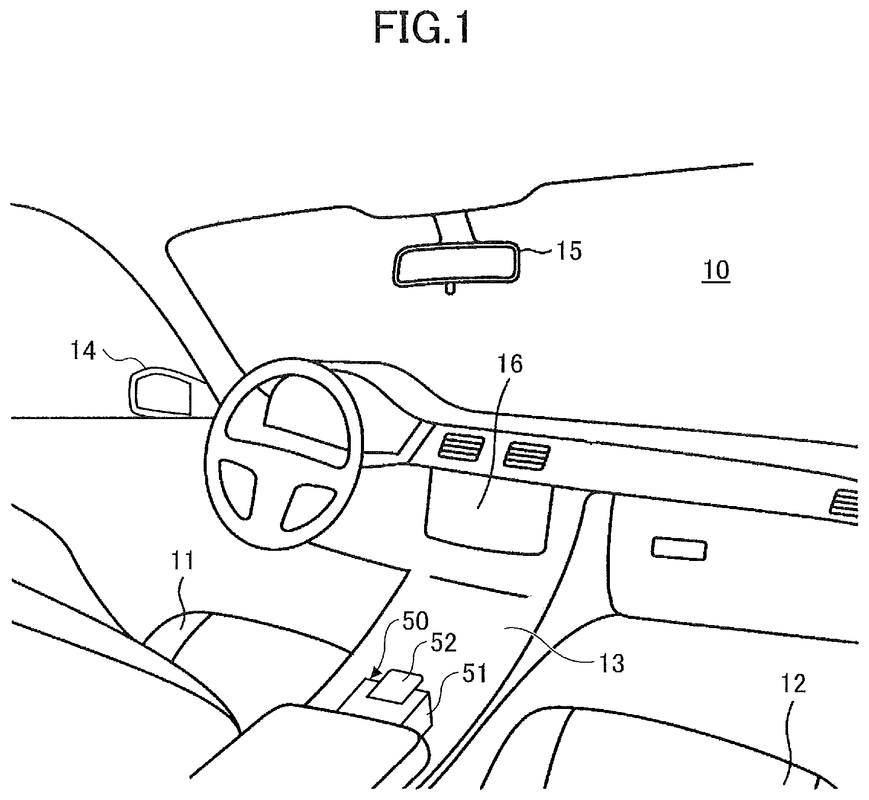
is a diagram illustrating an interior of a vehicle 10 mounted with an operation unit 50 according to one embodiment.
is a diagram illustrating an input device 100 according to one embodiment.
is an exploded view illustrating the input device 100 according to one embodiment.
is a top view illustrating the input device 100 according to one embodiment.
is a side view illustrating the input device 100 according to one embodiment.
is a diagram illustrating characteristics of a reaction force with respect to a flexing amount of a knob 130 .
is a diagram illustrating a circuit of the input device 100 .
is a diagram illustrating a manipulated direction of the knob 130 determined by a signal L/R and a signal U/D.
A is a flow chart illustrating a process of a determination unit 161 of the signal processor 160 , determining the manipulated direction of the knob 130 .
B is a flow chart illustrating the process of the determination unit 161 of the signal processor 160 , determining the manipulated direction of the knob 130 .
C is a flow chart illustrating the process of the determination unit 161 of the signal processor 160 , determining the manipulated direction of the knob 130 .
A is a diagram illustrating an operation example based on a control signal output from the signal processor 160 .
B is a diagram illustrating the operation example based on the control signal output from the signal processor 160 .
DETAILED DESCRIPTION
Hereinafter, embodiments applied with the input device and the operation unit according to the present invention will be described.
Embodiment
is a diagram illustrating an interior of a vehicle 10 mounted with an operation unit 50 according to one embodiment. The vehicle 10 includes a driver's seat 11 , a passenger's seat 12 , a center console 13 , an outer mirror 14 , an inner mirror 15 , and a display 16 . The operation unit 50 is provided on the center console 13 , disposed in the interior of the vehicle 10 , between the driver's seat 11 and the passenger's seat 12 . The operation unit 50 includes a main body 51 , and a knob 52 .
The operation unit 50 is provided for operating various devices of the vehicle 10 , and may be used to adjust the outer mirror 14 and the inner mirror 15 , for example. When a user manually bends the knob 52 in an up-and-down direction and a left-and-right direction, the outer mirror 14 and the inner mirror 15 can be adjusted in the up-and-down direction and the left-and-right direction.
is a diagram illustrating an input device 100 according to one embodiment. The input device 100 is accommodated inside the operation unit 50 of . The input device 100 includes a housing 110 , a lever 120 , a knob 130 , a flex sensor 140 , push switches 150 A and 150 B, substrates 151 A and 151 B, holders 152 A and 152 B, and pins 153 A and 153 B, as main constituent elements. In , a portion of the housing 110 (wall 110 B) is illustrated in a perspective.
The XYZ coordinate system will be defined and described in the following. For the sake of convenience, a negative Z-axis direction is referred to as a lower side or downward, and a positive Z-axis direction is referred to as an upper side or upward in the following description, however, the upper side and the lower side do not represent a universal up-and-down relationship. In the vehicle 10 illustrated in , a forward direction is a −Y-direction, a rear direction is a +Y-direction, a left direction is a +X-direction, a right direction is a −X-direction, the upper direction is a +Z-direction, and the downward direction is a −Z-direction.
In the following, a description will be given in conjunction with through , in addition to . is an exploded view illustrating the input device 100 according to one embodiment, is a top view illustrating the input device 100 according to one embodiment, and is a side view illustrating the input device 100 according to one embodiment.
The housing 110 includes a body portion 110 A, and the wall 110 B. The housing 110 is made of a resin, for example. The body portion 110 A has a generally parallelepiped shape with an upper portion having a shaped constricted toward the Y-axis direction, and includes an accommodating portion 110 A 1 for accommodating the lever 120 . The housing 110 is an example of a fixing member. The housing 110 is fixed inside the main body 51 of the operation unit 50 of .
The body portion 110 A includes a lower surface side (−Z-direction side) wall, a −X-direction side wall, and ±Y-direction side walls, surrounding the accommodating portion 110 A 1 , and continuously open on the +X-direction side and the +Z-direction side. The body portion 110 A also includes a bearing portion 111 A, a fixing portion 112 A, threaded holes 113 A, and a fixing portion 114 A.
The bearing portion 111 A is provided on an upper portion of the surface of the −X-direction side wall facing the +X-direction, and rotatably supports a rotating shaft 121 A on the −X direction side of the lever 120 .
The fixing portion 112 A is provided on surface of the −Y-direction side wall facing the +Y-direction, and the surface of the +Y-direction side wall facing the −Y-direction, and includes a threaded hole. The fixing portion 112 A is provided to fix the holders 152 A and 152 B by screws.
The threaded holes 113 A are provided at three positions in the wall of the body portion 110 A facing the opening on the +X-direction side of the body portion 110 A, and the wall 110 B is fixed by three screws 110 C.
The fixing portion 114 A includes four protrusions protruding in the ±X-directions at an intermediate position along the height direction of the body portion 110 A, and each of the four protrusions includes a through hole penetrating each protrusion in the Z-axis direction. The fixing portion 114 A is provided for inserting screws or pins when fixing the operation unit to the center console 13 of the vehicle 10 , as illustrated in as an example.
The wall 110 B is a plate member having a trapezoidal shape in a view perpendicular to a YZ-plane, and includes a bearing portion similar to the bearing portion 111 A provided on a surface facing in the −X-direction.
The body portion 110 A and the wall 110 B are fixed by the screws 110 C in a state where the lever 120 is accommodated in the accommodating portion 110 A 1 , the rotating shaft 121 A on the −X-direction side is inserted into the bearing portion 111 A, and a rotating shaft 121 A on the +X-direction side is inserted into the bearing portion of the wall 110 B, so that the housing 110 rotatably holds the lever 120 .
The lever 120 includes a base 121 , and an extending portion 122 . The lever 120 is made of a resin, for example. The base 121 is a member having a parallelepiped shape extending in the X-axis direction, and includes the rotating shafts 121 A which protrude from surfaces facing the ±X-directions. The lever 120 is an example of a movable member.
In addition, two threaded holes 121 B are provided in the surface of the base 121 facing the +Z-direction. Centers of the threaded holes 121 B in a plan view are located at positions directly above the two rotating shafts 121 A. A knob 130 is fixed to the threaded holes 121 B by screws 130 C. The extending portion 122 is integrally formed on the −Z-direction side of the base 121 .
When the lever 120 is rotated clockwise about the rotating shafts 121 A (in a direction of an arrow A in ) when viewed from the +X-direction, the push switch 150 A makes contact with the pin 153 A. When the lever 120 is rotated counterclockwise about the rotating shafts 121 A (in a direction of an arrow B in ), the push switch 150 B makes contact with the pin 153 B. The clockwise rotation and the counterclockwise rotation are examples of rotations in a first rotating direction and a second rotating direction, respectively.
The knob 130 is a thin plate member having a rectangular shape in the plan view, and is made of a resin, for example. The knob 130 is an example of a manipulating part. The flex sensor 140 is provided on the lower surface of the knob 130 . The knob 130 is a member that is manipulated by the user who performs an input operation to the input device 100 . The knob 130 has the threaded hole 131 at the +X direction end on the side facing the +Y-direction, and at the −X-direction end on the side facing the +Y direction. Centers of the threaded holes 131 are located at positions directly above the two rotating shafts 121 A.
In addition, corners at ends of the knob 130 along the ±X-directions, on the side facing the −Y-direction, are chamfered and curved in the plan view. The knob 130 is fixed to the upper end of the lever 120 , by fastening the screws 130 C inserted through the threaded holes 131 into the threaded holes 121 B of the lever 120 . Accordingly, in the direction in which the lever 120 extends from the rotating shafts 121 A (in the Z-axis direction in a state where the lever 120 is not rotated), the knob 130 is provided on the +Z-direction side of the rotating shafts 121 A. The +Z-direction side of the rotating shafts 121 A is an example of a first side.
A knob 52 illustrated in is fixed to the knob 130 . The knob 52 is fixed to the knob 130 by fitting, fastening screw, bonding, or the like, and operates integrally with the knob 130 .
Because the +Y-direction side of the knob 130 is fastened to the lever 120 by screws, a portion of the knob 130 , which is closer to the −Y-direction side than a portion of the knob 130 in contact with the lever 120 , is deformed by flexing when pressed by a user's hand or the like. The knob 130 is manipulated by applying a force to the left side (+X side) of the portion of the knob 130 closer to the −Y-direction side than the portion of the knob 130 in contact with the lever 120 , to flex upward or downward, or to the right side (−X side) of the portion of the knob 130 closer to the −Y-direction side than the portion of the knob 130 in contact with the lever 120 , to flex upward or downward.
The left side of the knob 130 is a first direction side along an axial direction (X-axis direction) of the rotating shafts 121 A, and the right side of the knob 130 is a second direction side. In this case, the first direction is the +X-direction, and the second direction is the −X-direction.
Hence, when the force is applied to the knob 130 (knob 130 is pressed), the lever 120 rotates clockwise or counterclockwise about the rotating shafts 121 A when viewed from the +X-direction, and the push switch 150 A makes contact with the pin 153 A, or the push switch 150 B makes contact with the pin 153 B.
In this state, the lever 120 and the knob 130 operate as levers. A fulcrum is the rotating shafts 121 A. A point of effort is a point of the knob 130 touched by the user's hand or the like. A point of load is a pressing point of the push switches 150 A and 150 B which are mounted on the lever 120 via the substrates 151 A and 151 B. The pressing point of the push switches 150 A and 150 B may be the point of the push switches 150 A and 150 B pressed directly or indirectly by the rotating operation of lever 120 .
For this reason, the pressing point of the push switches 150 A and 150 B may be the point where the pins 153 A and 153 B make contact with surfaces of the push switches 150 A and 150 B which are mounted on the lever 120 via the substrates 151 A and 151 B. The pressing point of the push switches 150 A and 150 B may be point where the push switches 150 A and 150 B are mounted on the substrates 151 A and 151 B. In addition, the pressing point of the push switches 150 A and 150 B may be point where the substrates 151 A and 151 B, mounted with the push switches 150 A and 150 B, are mounted on the lever 120 .
The flex sensor 140 is provided to detect the input manipulated direction of the knob 130 , by detecting a flexing direction generated in the knob 130 . The flex sensor 140 is illustrated in a simplified manner in and , however, includes three sensor portions (sensors 141 , 142 , and 143 ) as more particularly illustrated in . The sensors 141 through 143 have an elongated sensor element shape in the plan view, and detect flexing (deformation) in a longitudinal direction.
As illustrated in , the sensor 143 is arranged so as to extend in the Y-axis direction (the longitudinal direction is parallel to the Y axis) at the center along the X-axis direction of the knob 130 . The sensors 141 and 142 are provided in line symmetry, with respect to an axis of symmetry formed by a center line which extends in the Y-axis direction and passes a center of a width of the sensor 143 taken along the X-axis direction.
A center axis 121 A 1 of the rotating shafts 121 A is indicated by a dashed line. The longitudinal direction of the sensors 141 and 142 forms an angle of 45 degrees with respect to the center axis 121 A 1 of the rotating shafts 121 A, and the longitudinal direction of the sensor 143 forms an angle of 90 degrees with respect to the center axis 121 A 1 of the rotating shafts 121 A. In other words, the sensors 141 , 143 , and 142 extend in a 45-degree direction, a 90-degree direction, and a 135-degree direction with respect to the center axis 121 A 1 of rotating shafts 121 A, respectively.
The push switches 150 A and 150 B are switches capable of switching between electrically on (conducting) and off (non-conducting) states, and are provided in triplicate, respectively. Three push switches 150 A and three push switches 150 B are provided, in order to adjust an operating load of the knob 130 to a desired load. The push switches 150 A and 150 B are examples of switches.
In relation to the position of the lever 120 , in a direction in which the lever 120 extends from the rotating shafts 121 A (in the Z-axis direction in a state where the lever 120 is not rotated), the push switches 150 A and 150 B are provided on the −Z-direction side of the rotating shafts 121 A. The −Z-direction side of the rotating shafts 121 A is an example of a second side.
Three push switches 150 A are mounted on the surface of the substrate 151 A facing the −Y-direction. The substrate 151 A is fastened by screws to the surface of the extending portion 122 of the lever 120 , facing the −Y-direction, by inserting screws 151 A 2 into through holes 151 A 1 . The three push switches 150 A are arranged in the X-axis direction at the same height position. The push switches 150 A are an example of a first switch part.
The push switch 150 A has a built-in spring, and switches from an off state to an on state when a predetermined pressing force is applied to release the spring. The push switch 150 A is a normally-open switch that is held in the on state while being pressed in the on state, and switches to the off state when no longer pressed.
A normally-closed switch may be used for the push switch 150 A, in place of the normally-open switch. In this case, the switch is held in the off state while being pressed, and switches to the on state when no longer pressed.
The push switch 150 A switches from the off state to the on state when the predetermined pressing force is applied to release the spring, and the pressing force required to hold the push switch 150 A in the pressed state rapidly decreases. The push switch 150 A of this type can provide a sense of click to the user's hand or the like manipulating the knob 130 .
Similar to the push switches 150 A, the push switches 150 B are switches capable of switching between electrically on (conducting) and off (non-conducting) states, and three push switches 150 B are provided on the surface of the substrate 151 B casing the +Y-direction. The push switches 150 B are an example of a second switch part.
The push switch 150 B is a normally-open switch, similar to the push switch 150 A, however, a normally-closed switch may be used in place of the normally-open switch. In this case, the switch is held in the off state while being pressed, and switches to the on state when no longer pressed.
The substrate 151 B is fixed to the surface of the extending portion 122 of the lever 120 , facing the +Y-direction, by fastening screws 151 B 2 inserted into through holes 151 B 1 . The three push switches 150 B are arranged along the X-axis direction at the same height position. Similar to the push switch 150 A, the push switch 150 B can provide a sense of click to the user's hand or the like manipulating the knob 130 .
The holder 152 A is a member that is held by inserting three pins 153 A therethrough, and is fixed in a state where the pins 153 A are inserted into three through holes 152 A 1 . The pin 153 A may be fixed in the through hole 152 A 1 by fitting, bonding, or the like.
The holder 152 A has through holes 152 A 2 that penetrate protrusions, protruding in the ±Z-direction, in the X-axis direction, and is fixed to the body portion 110 A by fastening screws 155 inserted into through hole 152 A 2 to the fixing portion 112 A of the body portion 110 A.
The positions of the three pins 153 A are aligned to the positions of the three push switches 150 A. The three pins 153 A press the push switches 150 A when the knob 130 is manipulated and the lever 120 rotates in the direction of the arrow A illustrated in . The push switches 150 A act as spring members for restricting the rotation of the lever 120 until a predetermined pressing force is applied.
The holder 152 B is a member that is held by inserting three pins 153 B therethrough, and is fixed in a state where the pins 153 B are inserted into three through holes 152 B 1 . The holder 152 B has through holes 152 B 2 that penetrate protrusions, protruding in the ±Z-direction, in the X-axis direction. The holder 152 B is fixed to the body portion 110 A by fastening screws 155 inserted into through hole 152 B 2 to a fixing portion (fixing portion similar to the fixing portion 112 A) of the body portion 110 A.
The positions of the three pins 153 B are aligned to the positions of the three push switches 150 B. The three pins 153 B press the push switches 150 B when the knob 130 is manipulated and the lever 120 rotates in the direction of the arrow B illustrated in . The push switches 150 B act as spring members for restricting the rotation of the lever 120 until a predetermined pressing force is applied.
is a diagram illustrating characteristics of a reaction force with respect to a flexing amount of the knob 130 . The knob 130 can be deformed, when a portion of the knob 130 , which is closer to the −Y-direction side than the portion in contact with the lever 120 , flexes. When the user applies a force on the knob 130 by the hand or the like to deform the knob 130 in the manner described above, a reaction force is applied to the user's hand or the like. This reaction force is the operating load of the knob 130 .
A flexing amount of the knob 130 in the Z-axis direction is a stroke of the knob 130 of the input device 100 , and indicates a stroke of the end of the knob 130 facing the Y-direction stroke along the Z-direction. The reaction force is a reaction force of the knob 130 acting on the user's hand or the like, and is an actuation force required to actuate the push switches 150 A and 150 B by manipulating the knob 130 .
The knob 130 and the push switches 150 A and 150 B may be regarded as springs, and a spring constant may be denoted by k. The knob 130 and the push switches 150 A and 150 B are designed, so that a reaction force F becomes a target value F1 when a flexing amount M of the knob 130 reaches a target value M1, and the springs of the push switches 150 A and 150 B are released to provide the sense of click.
As illustrated in , if a distance from a center of the rotating shafts 121 A on the XZ-plane to a position (manipulating position) where the knob 130 is manipulated is denoted by L1, a distance from the center of the rotating shafts 121 A to a center of the switches 150 A and 150 B is denoted by L2, and a pressing force required to release the springs of the switches 150 A and 150 B is denoted by Fs, the reaction force F that can provide the sense of click can be expressed by the following formula (1). F=L 2/ L 1× Fs (1)
The flexing amount M of the knob 130 at the manipulating position in this state can be expressed by the following formula (2). M=F/k=Fs/k×L 2/ L 1 (2)
As illustrated in , when the flexing amount M of the knob 130 increases, the reaction force F also increases, and when the flexing amount M reaches the target value M1, the springs of the push switches 150 A and 150 B are released, so that the reaction force decreases slightly. At this point in time, the push switches 150 A and 150 B are in a state (completely squeezed state) where the push switches 150 A and 150 B cannot be pressed further. Hence, because the springs of the push switches 150 A and 150 B are released to slightly decrease the reaction force, it is possible to provide the sense of click to the user's hand or the like touching the knob 130 . By setting a stiffness of knob 130 and the pressing force Fs on the push switches 150 A and 150 B to suitable values, it is possible to provide a desired sense of click.
However, in this case, it is necessary to set the material and the size (lengths in the X-axis and Y-axis directions, a thickness in the Z-axis direction, or the like) of the knob 130 , so that the sense of click can be provided in an operating range less than or equal to a yield stress of the knob 130 .
is a diagram illustrating a circuit of the input device 100 . The input device 100 includes a sensor circuit 140 A, and in the sensor circuit 140 A, the sensors 141 and 142 of the flex sensor 140 and a resistor R 1 are connected in series between a power supply Vcc and ground. In addition, the sensor 143 and resistors R 2 and R 3 are connected in series between the power supply Vcc and the ground. Further, capacitors C 1 through C 4 are provided at positions illustrated in .
Moreover, the input device 100 includes a signal processor 160 . The signal processor 160 includes an information processor, such as a microcomputer, and an Analog-to-Digital Converter (ADC). illustrates a determination unit 161 and a control signal output unit 162 which are formed by the information processor of the signal processor 160 . The determination unit 161 and the control signal output unit 162 represent functional blocks of the information processor of the signal processor 160 .
A signal L/R indicating a voltage value of a node between the sensors 141 and 142 , a signal U/D indicating a voltage value of a node between the resistor R 3 and the sensor 143 , and signals A and B indicating on and off states of the push switches 150 A and 150 B, are input to the signal processor 160 . The signal L/R and the signal U/D are an example of first output signals.
The signal L/R is a signal indicating whether the input operation to the knob 130 is performed in the leftward (left) direction or the rightward (right) direction. In addition, the signal U/D is a signal indicating whether the input operation to the knob 130 is performed in the upward (up) direction or the downward (down) direction.
The signal L/R and the signal U/D are subjected to analog-to-digital (A/D) conversion before being input to the determination unit 161 . Based on the A/D converted signals L/R and U/D, the determination unit 161 determines the direction in which the knob 130 is manipulated, from among an upper left direction, a lower left direction, an upper right direction, and a lower right direction.
In addition, the determination unit 161 detects the on and off states of the push switches 150 A and 150 B, based on the signals A and B. The signals A and B are an example of second output signals.
The control signal output unit 162 outputs a control signal indicating a determination result of the manipulated direction of the knob 130 , and a determination result of the on and off states of the push switches 150 A and 150 B. Further, the control signal output unit 162 outputs a magnitude of both or one of the first output signals, namely, the signal L/R and the signal U/D, as the A/D converted digital value for the control signal.
is a diagram illustrating the manipulated direction of the knob 130 determined by the signal L/R and the signal U/D. In , the abscissa indicates a signal level (voltage value) of the signal L/R, and the higher the signal level of the signal L/R becomes towards the right side of the abscissa. The ordinate indicates a signal level (voltage value) of the signal U/D, and the higher the signal level of the signal. U/D becomes towards the upper side of the ordinate.
The signal L/R has a property such that the signal level increases when the left side of the knob 130 is manipulated in the upward direction and flexes, and when the right side of the knob 130 is manipulated in the downward direction and flexes, and the signal level decreases when the left side of the knob 130 is manipulated in the downward direction and flexes, and when the right side of the knob 130 is manipulated in the upward direction and flexes.
Moreover, the signal U/D has a property such that the signal level increases when the left side of the knob 130 is manipulated in the upward direction and flexes, and when the right side of the knob 130 is manipulated in the upward direction and flexes, and the signal level decreases when the left side of the knob 130 is manipulated in the downward direction and flexes, and when the right side of the knob 130 is manipulated in the downward direction and flexes.
For this reason, when the signal L/R is plotted on the abscissa and the signal U/D is plotted on the ordinate, as illustrated in , the distributions of the signal levels of the signal L/R and the signal U/D become as illustrated in when the knob 130 is manipulated toward the upper right, the upper left, the lower right, or the lower left.
In , a no-operation region is a region where the determination unit 161 of the signal processor 160 determines that the knob 130 is not manipulated, and is set to a cross-shaped portion at center portions of the signal levels of the signal L/R and the signal U/D, as indicated by a dashed line. A voltage value of the signal L/R at the center of the no-operation region is Vc, a voltage value of the signal L/R at a lower limit of the no-operation region is V 1 , and a voltage value of the signal L/R at an upper limit of the no-operation region is V 2 . A voltage value of the signal U/D at the center of the no-operation region is Vm, a voltage value of the signal U/D at the lower limit of the no-operation region is V 3 , and a voltage value of the signal U/D at the upper limit of the no-operation region is V 4 . The no-operation region is a region where at least one of the signal L/R in a range higher than or equal to V 1 and lower than or equal to V 2 , and the signal U/D in a range higher than or equal to V 3 and lower than or equal to V 4 , is satisfied.
If the signal L/R is lower than the lower limit voltage V 1 of the no-operation region, the determination unit 161 determines that the knob is manipulated toward the upper right or the lower left, and if the signal L/R is higher than the upper limit voltage V 2 of the no-operation region, the determination unit 161 determines that the knob is manipulated toward the upper left or the lower right.
In addition, if the signal U/D is lower than the lower limit voltage V 3 of the no-operation region, the determination unit 161 determines that the knob is manipulated in toward the lower left or the lower right, and if the signal U/D is higher than the upper limit voltage V 4 of the no-operation region, the determination unit 161 determines that the knob is manipulated toward the upper right or the upper left.
A through C are flow charts illustrating a process of the determination unit 161 of the signal processor 160 , determining the manipulated direction of the knob 130 . The determination unit 161 stores a signal level (a center voltage value Vc of the no-operation region) of the signal L/R and the signal U/D, in a state where the knob 130 is not manipulated.
The determination unit 161 reads the signal L/R and the signal U/D (step S 1 ).
The determination unit 161 determines whether or not the signal L/R is greater than the center voltage value Vc (step S 2 ). A case where the signal L/R is greater than the center voltage value Vc, corresponds to a state where the knob 130 is manipulated toward the upper left or the lower right.
If the determination unit 161 determines that the signal L/R is greater than the center voltage value Vc (YES in S 2 ), the determination unit 161 calculates a variation of the signal L/R (step S 3 ). This variation of the signal L/R is a difference of the level of the signal L/R calculated in step S 3 of the current control cycle, with respect to the level of the signal L/R calculated in step S 3 of the previous control cycle.
The determination unit 161 determines whether or not the variation of the signal L/R is greater than the upper limit voltage V 2 of the no-operation region (step S 4 ).
If the determination unit 161 determines that the variation of the signal L/R is greater than the upper limit voltage V 2 of the no-operation region (YES in S 4 ), the determination unit 161 determines whether or not the signal U/D is greater than the center voltage value Vm (step S 5 ). A case where the signal U/D is greater than the center voltage value Vm, corresponds to a state where the knob 130 is manipulated toward the upper right or the upper left.
If the determination unit 161 determines that the signal U/D is greater than the center voltage value Vm (YES in S 5 ), the determination unit 161 calculates a variation of the signal U/D (step S 6 ). This variation of the signal U/D is a difference of the level of the signal U/D calculated in step S 6 of the current control cycle, with respect to the level of the signal U/D calculated in step S 6 of the previous control cycle.
The determination unit 161 determines whether or not the variation of the signal U/D is greater than the upper limit voltage V 4 of the no-operation region (step S 7 ).
If the determination unit 161 determines that the variation of the signal U/D is greater than the upper limit voltage V 4 of the no-operation region (YES in S 7 ), the determination unit 161 determines that the knob 130 is manipulated toward the upper left (step S 8 ).
In addition, if the determination unit 161 determines in step S 7 that the variation of the signal U/D is not greater than the upper limit voltage V 4 of the no-operation region (NO in S 7 ), the determination unit 161 determines that the knob 130 is not manipulated (step S 9 ).
Moreover, if the determination unit 161 determines in step S 4 that the variation of the signal L/R is not greater than the upper limit voltage V 2 of the no-operation region (No in S 4 ), the determination unit 161 ends the process (end).
Further, if the determination unit 161 determines in step S 5 that the signal U/D is not greater than the center voltage value Vc (No in S 5 ), the determination unit 161 calculates a variation of the signal U/D (step S 10 ). This variation of the signal U/D is a difference of the level of the signal U/D calculated in step S 10 of the current control cycle, with respect to the level of the signal U/D calculated in step S 10 of the previous control cycle.
The determination unit 161 determines whether or not the variation of the signal U/D is less than the lower limit voltage V 3 of the no-operation region (step S 11 ).
If the determination unit 161 determines that the variation of the signal U/D is less than the lower limit voltage V 3 of the no-operation region (YES in S 11 ), the determination unit 161 determines that the knob 130 is manipulated toward the lower right (step S 12 ).
In addition, if the determination unit 161 determines in step S 11 that the variation of the signal U/D is not less than the lower limit voltage V 3 of the no-operation region (No in S 11 ), the determination unit 161 determines that the knob 130 is not manipulated (step S 13 ).
Moreover, if the determination unit 161 determines that the signal L/R is not greater than the center voltage value Vc (NO in S 2 ), the determination unit 161 calculates a variation of the signal L/R (step S 14 ). This variation of the signal L/R is a difference of the level of the signal L/R calculated in step S 14 of the current control cycle, with respect to the level of the signal L/R calculated in step S 14 of the previous control cycle.
The determination unit 161 determines whether or not the variation of the signal L/R is less than the lower limit voltage V 1 of the no-operation region (step S 15 ).
If the determination unit 161 determines that the variation of the signal L/R is less than the lower limit voltage V 1 of the no-operation region (YES in S 15 ), the determination unit 161 determines whether or not the signal U/D is greater than the center voltage value Vm (step S 16 ). A case where the signal U/D is greater than the center voltage value Vm, corresponds to a state where the knob 130 is manipulated toward the upper right or the upper left.
If the determination unit 161 determines that the signal U/D is greater than the center voltage value Vm (YES in S 16 ), the determination unit 161 calculates a variation of the signal U/D (step S 17 ). This variation of the signal U/D is a difference of the level of the signal U/D calculated in step S 17 of the current control cycle, with respect to the level of the signal U/D calculated in step S 17 of the previous control cycle.
The determination unit 161 determines whether or not the variation of the signal U/D is greater than the upper limit voltage V 4 of the no-operation region (step S 18 ).
If the determination unit 161 determines that the variation of the signal U/D is greater than the upper limit voltage V 4 of the no-operation region (YES in S 18 ), the determination unit 161 determines that the knob 130 is manipulated toward the upper right (step S 19 ).
In addition, if the determination unit 161 determines in step S 18 that the variation of the signal U/D is not greater than the upper limit voltage V 4 of the no-operation region (NO in S 18 ), the determination unit 161 determines that the knob 130 is not manipulated (step S 20 ).
Moreover, if the determination unit 161 determines in step S 15 that the variation of the signal L/R is not greater than the lower limit voltage V 1 of the no-operation region (NO in S 15 ), the determination unit 161 ends the process (end).
Further, if the determination unit 161 determines in step S 16 that the signal U/D is not greater than the center voltage value Vm (NO in S 16 ), the determination unit 161 calculates a variation of the signal U/D (step S 21 ). This variation of the signal U/D is a difference of the level of the signal U/D calculated in step S 21 of the current control cycle, with respect to the level of the signal U/D calculated in step S 21 of the previous control cycle.
The determination unit 161 determines whether or not the variation of the signal U/D is smaller than the lower limit voltage V 3 of the no-operation region (step S 22 ).
If the determination unit 161 determines that the variation of the signal U/D is less than the lower limit voltage V 3 of the non-operation region (YES in S 22 ), the determination unit 161 determines that the knob 130 is manipulated toward the lower left (step S 23 ).
In addition, if the determination unit 161 determines in step S 22 that the variation of the signal U/D is not less than the lower limit voltage V 3 in the no-operation region (NO in S 22 ), the determination unit 161 determines that the knob 130 is not manipulated (step S 24 ).
A and B are diagrams illustrating an operation example based on the control signal output from the signal processor 160 . As an example, an operation example in which the vehicle 10 (refer to ) is equipped with a camera configured to acquire the rear image, and a display, which is provided in place of the inner mirror 15 , and is configured to display the rear image captured by the camera, and a range to be displayed on the display is adjusted by the input device 100 , will be described.
A illustrates a visual field 15 A displayable on the display, and a movable range 15 B of the visual field 15 A. Because the determination unit 161 performs the process illustrated in A through C , and can determine whether the input operation to the knob 130 is a manipulation in a direction of one of the upper left direction, the lower left direction, the upper right direction, and the lower right direction, it is possible to move the visual field 15 A within the movable range 15 B in the direction indicated by the determination result, as illustrated in B .
For example, if the visual field 15 A is being moved in the direction of one of the upper left, the lower left, the upper right, and the lower right according to the manipulated direction of the knob 130 , the position of the visual field 15 A becomes fixed when the magnitudes of the first output signals are maintained in a constant state for a predetermined time. On the other hand, when the push switch 150 A or 150 B is turned on, the visual field 15 A is adjusted to a preset position.
As described above, the input device 100 can determine whether the manipulated direction of the knob 130 is the direction toward the upper left, the lower left, the upper right, or the lower right, based on the signal L/R and the signal U/D obtained from the flex sensor 140 . The input device 100 can also detect the on and off states of the push switches 150 A and 150 B. The input device 100 can also output the control signal according to the magnitudes of the first output signals.
Accordingly, it is possible to provide the input device 100 which outputs the control signal according to the manipulated direction and the manipulated amount, and the operation unit 50 .
The push switches 150 A and three push switches 150 B are provided in the embodiment described above. However, at least one push switch 150 A and at least one push switch 150 B may be provided. In this case, the number of push switches 150 A and the number of push switches 150 B on both sides of the lever 120 are desirably the same, from a viewpoint of making the operating load of the knob 130 uniform in the upward and downward directions.
In addition, when a plurality of push switches 150 A and a plurality of push switches 150 B are provided, the plurality of push switches 150 A except for one, and the plurality of push switches 150 B except for one, may be dummy push switches which are merely used to generate a load and do not output an on or off signal. Alternatively, the load may be adjusted using an elastic member, such as a spring, rubber, or the like, in place of the dummy push switch.
Although the flex sensor 140 is used to detect the flexing of knob 130 in the embodiment described above, a sensor, which detects a displacement due to deformation of the knob 130 , may be used instead of the flex sensor 140 . For example, a piezoelectric element may be used for such a sensor.
The push switches 150 A and 150 B are fixed to the lever 120 through the substrates 151 A and 151 B in the embodiment described above. However, the push switches 150 A and 150 B may be mounted on the wall of the body portion 110 A of the housing 110 facing the accommodating portion 110 A 1 , and configured to be pressed by the pins 153 A and 153 B as the lever 120 rotates.
According to the embodiments of the present disclosure, it is possible to provide an input device and an operation unit, which output signals indicating a manipulated direction, and on and off states according to a manipulated amount.
Although preferable embodiments or the like are described in detail above, the present disclosure is not limited to the embodiments or the like described above, and various variations, modifications, and substitutions may be made to the embodiments or the like described above without departing from the scope of the present disclosure.
Figures (12)
Citations
This patent cites (14)
- US5666138
- US6618037
- US7465890
- US20060054479
- US1619740
- US106057537
- USH10-260097
- US2002-007065
- US2004-164929
- US2005-63936
- US2008-257296
- US2010-244858
- US2011-34796
- US2011-238061