Complex Irrigation/suction Flow Path in a Medical Device
Abstract
A suction/irrigation medical device comprises a valve body having one or more conduits fluidically coupled thereto and a first channel extending through the valve body. The medical device also comprises a first valve plunger disposed along the first channel and configured to move along an axis to open and close the first channel. The first valve plunger has a first opening to permit a fluid to flow through the first channel. The medical device also comprises a second valve plunger disposed along the first channel and along a second channel to couple the second channel into the first channel when the second valve plunger is in a first position. The second valve plunger has a second opening that has at least one dimension that is greater than a corresponding dimension of the first opening of the first valve plunger.
Claims (20)
1. A suction/irrigation medical device comprising: a valve body having one or more conduits fluidically coupled thereto; a first channel extending through the valve body, the first channel comprising a proximal portion, a middle portion, and a distal portion, wherein a central axis extends through the first channel, and wherein the proximal, middle, and distal portions of the first channel are aligned along the central axis; a first valve plunger disposed along the first channel and configured to move along a first axis to open and close the first channel, the first valve plunger including a first opening coupling the proximal and middle portions of the first channel when the first valve plunger is in a first position; and a second valve plunger disposed along the first channel and along a second channel extending through the valve body, the second valve plunger having a second opening coupling the middle and distal portions of the first channel and coupling the second channel to the distal portion of the first channel when the second valve plunger is in a first position, the second opening of the second valve plunger including at least one dimension that is greater than a corresponding dimension of the first opening of the first valve plunger.
13. A medical device comprising: a valve body including: a first fluid channel comprising a proximal portion, a middle portion, and a distal portion, wherein a central axis extends through the first fluid channel, and wherein the proximal, middle, and distal portions of the first fluid channel are aligned along the central axis; a second fluid channel; a first valve channel intersecting the first fluid channel; and a second valve channel intersecting the first and second fluid channels; a first valve plunger extending within the first valve channel and including a first opening coupling the proximal and middle portions of the first fluid channel when the first valve plunger is in a first position; and a second valve plunger extending within the second valve channel and including a second opening coupling the middle and distal portions of the first fluid channel and coupling the second fluid channel to the distal portion of the first fluid channel when the second valve plunger is in a first position.
Show 18 dependent claims
2. The medical device of claim 1 , wherein the second valve plunger is longer than the first valve plunger.
3. The medical device of claim 1 , wherein the first channel is straight and the second channel has at least one bend.
4. The medical device of claim 1 , wherein a bias element biases the first valve plunger to a position in which the first channel is closed.
5. The medical device of claim 1 , wherein a bias element biases the second valve plunger to a position in which the first channel is open and the second channel is closed.
6. The medical device of claim 1 , wherein the at least one dimension is length and the length of the second opening of the second valve plunger is at least two times greater than the length of the first opening of the first valve plunger.
7. The medical device of claim 1 , wherein the valve body has a first tubing coupler and a second tubing coupler, wherein the first tubing coupler is aligned with the first channel and enables a first tubing to be secured in communication with the first channel and the second tubing coupler is disposed at an angle relative to the first channel and enables a second tubing to be secured in communication with the second channel.
8. The medical device of claim 1 , wherein the first channel is in communication with an elongate instrument having an end effector at a distal end thereof.
9. The medical device of claim 1 , wherein the first channel includes a distal opening and a proximal opening and wherein the distal and proximal openings are aligned along the central axis extending through the first channel.
10. The medical device of claim 1 , wherein when the second valve plunger is in the first position, a first fluid path extends through the first channel and the second opening and a second fluid path extends through the second channel and the second opening.
11. The medical device of claim 10 , wherein the second fluid path includes a portion that bends approximately 90 degrees relative to the first fluid path.
12. The medical device of claim 1 , wherein the second valve plunger includes a sealing member and when the second valve plunger is in a second position, the sealing member obstructs a junction between the second channel and the first channel.
14. The medical device of claim 13 , wherein the second valve plunger is longer than the first valve plunger.
15. The medical device of claim 13 , wherein the first fluid channel is straight and the second fluid channel has at least one bend.
16. The medical device of claim 13 , wherein a bias element biases the first valve plunger to a position in which the first fluid channel is closed, obstructing a flow of a first fluid through the first fluid channel.
17. The medical device of claim 13 , wherein a bias element biases the second valve plunger to a position in which the first fluid channel is open and the second fluid channel is closed, obstructing a flow of a second fluid through the second fluid channel.
18. The medical device of claim 13 , wherein a length of the second opening of the second valve plunger is at least two times greater than a length of the first opening of the first valve plunger.
19. The medical device of claim 13 , wherein the first fluid channel includes a distal opening and a proximal opening and wherein the distal and proximal openings are aligned along the central axis extending through the first fluid channel.
20. The medical device of claim 13 , wherein when the second valve plunger is in the first position, a first fluid path extends through the first fluid channel and the second opening and a second fluid path extends through the second fluid channel and the second opening.
Full Description
Show full text →
PRIORITY INFORMATION
This application is continuation of U.S. patent application Ser. No. 15/897,832, filed Feb. 15, 2018, which is a non-provisional application claiming priority to U.S. Provisional Application No. 62/459,708, filed Feb. 16, 2017, the disclosures of which are incorporated herein by reference in their entirety.
FIELD
The present disclosure relates generally to medical instruments, and more particularly to the flow path of steerable and articulate medical instruments having robotically actuated features and manually actuated features.
BACKGROUND
In the field of robotic surgery and machine-aided medical procedures there is the need to rapidly and efficiently introduce material to, and remove material from, the interventional area. For example, in some situations it, is desirable to remove blood or other liquid or solid material accumulation near the interventional site in order to maintain good visibility for the physicians. Similarly, it is desirable to remove smoke during endoscopic procedures to maintain good visibility. In some situations it is desirable to introduce a gas to inflate a body cavity that includes an organ or a tissue that is involved in surgery. Such insufflation provides sufficient space for the physician to manually or robotically manipulate instruments and for an adequate endoscopic field of view. In other situations, it may be desirable to irrigate the interventional area (e.g., with water or a saline solution), either for allowing visibility of the area of interest or to provide moisture to the tissue surrounding the area of interest.
However, some conventional irrigation/suction instruments can become clogged as material moves through the flow path. This decreases the performance of such instruments and can lead to decreased visibility and slower removal of material from the interventional site. What is needed is a medical instrument that provides the improved performance during suction and irrigation operation.
SUMMARY
The embodiments of the invention are best summarized by the claims that follow the description.
Consistent with some embodiments, a suction/irrigation medical device is provided. An exemplary suction/irrigation medical device includes a valve body having one or more conduits fluidically coupled thereto, a first channel extending through the valve body, and first and second valve plungers. The first valve plunger is disposed along the first channel and is configured to move along an axis to open and close the first channel. The first valve plunger has a first opening to permit a fluid to flow through the first channel. The second valve plunger is disposed along the first channel and along a second channel to couple the second channel into the first channel when the second valve plunger is in a first position. The second valve plunger has a second opening that has at least one dimension that is greater than a corresponding dimension of the first opening of the first valve plunger.
Consistent with some embodiments, a valve system is provided. An exemplary valve system includes first and second valve plungers. The first valve plunger is configured for insertion into a first valve plunger channel and has a first latch member disposed at a distal end, a first sealing member, and a first valve opening disposed proximally from the first latch member. The second valve plunger is configured for insertion into a second valve plunger channel and has a second valve opening that is longer than the first valve opening. The exemplary valve system further includes a valve body having the first and second valve plunger channels, the first and second valve plunger channels being configured to receive the first and second valve plungers, respectively.
Consistent with some embodiments, a medical system is provided. An exemplary medical system includes a backend housing that receives a first conduit and a second conduit. The first conduit configured for communication with a pressurized fluid source and the second conduit configured for communication with a vacuum source. The backend house further contains a valve body coupled to the first and second conduits, the valve body including a first valve plunger channel and a second valve plunger channel. The backend housing further contains first and second valve plungers. The first valve plunger being is into the first valve plunger channel and includes a first valve opening. The second valve plunger being inserted into the second valve plunger channel, the second valve plunger including a second valve opening that is longer than the first valve opening, with the first valve plunger channel being configured in parallel with the second valve plunger channel. The backend housing further includes a first manual actuation button coupled to the first valve plunger and a second manual actuation button coupled to the second valve plunger. The exemplary medical system further includes an elongate instrument shaft protruding distally from a chassis portion the backend housing. The chassis portion is configured to couple to a robotic control interface to permit remote control of the first valve plunger and the second valve plunger.
Consistent with some embodiments, another medical device is provided. An exemplary medical device includes a valve body, in which a first fluid channel and a second fluid channel are defined, wherein the first fluid channel extends through the valve body and comprises a proximal portion, a middle portion, and a distal portion, and wherein the second fluid channel extends into the valve body. The exemplary medical device further includes a first valve plunger and a second valve plunger. The first valve plunger includes a first fluid path is defined therethrough. The first plunger is movable between a first position, in which the first valve plunger is positioned to obstruct fluid flow between the proximal and middle portions of the first channel, and a second position, in which the first fluid path couples the proximal and middle portions of the first fluid channel. The second valve plunger includes a second fluid path is defined therein. The second plunger is movable between a first position, in which the second fluid path is positioned to couple the middle and distal portions of the first fluid channel and to obstruct fluid flow between the second channel and the distal portion of the first channel, and a second position, in which the second fluid path couples the second fluid channel to the distal portion of the first fluid channel.
Consistent with some embodiments, another medical device is provided. An exemplary medical device includes a first fluid channel defined in the medical device and a second fluid channel defined in the medical device. The exemplary medical device further includes a first valve plunger comprising a button comprising a convex top surface and a second valve plunger comprising a button comprising a concave top surface. The first valve plunger is positioned to control a fluid flow in the first fluid channel. The second valve plunger is positioned to control a fluid flow in the second fluid channel. The button of the first valve plunger and the button of the second valve plunger are positioned adjacent one another.
It is to be understood that both the foregoing general description and the following detailed description are exemplary and explanatory in nature and are intended to provide an understanding of the present disclosure without limiting the scope of the present disclosure. In that regard, additional aspects, features, and advantages of the present disclosure will be apparent to one skilled in the art from the following detailed description.
BRIEF DESCRIPTIONS OF THE DRAWINGS
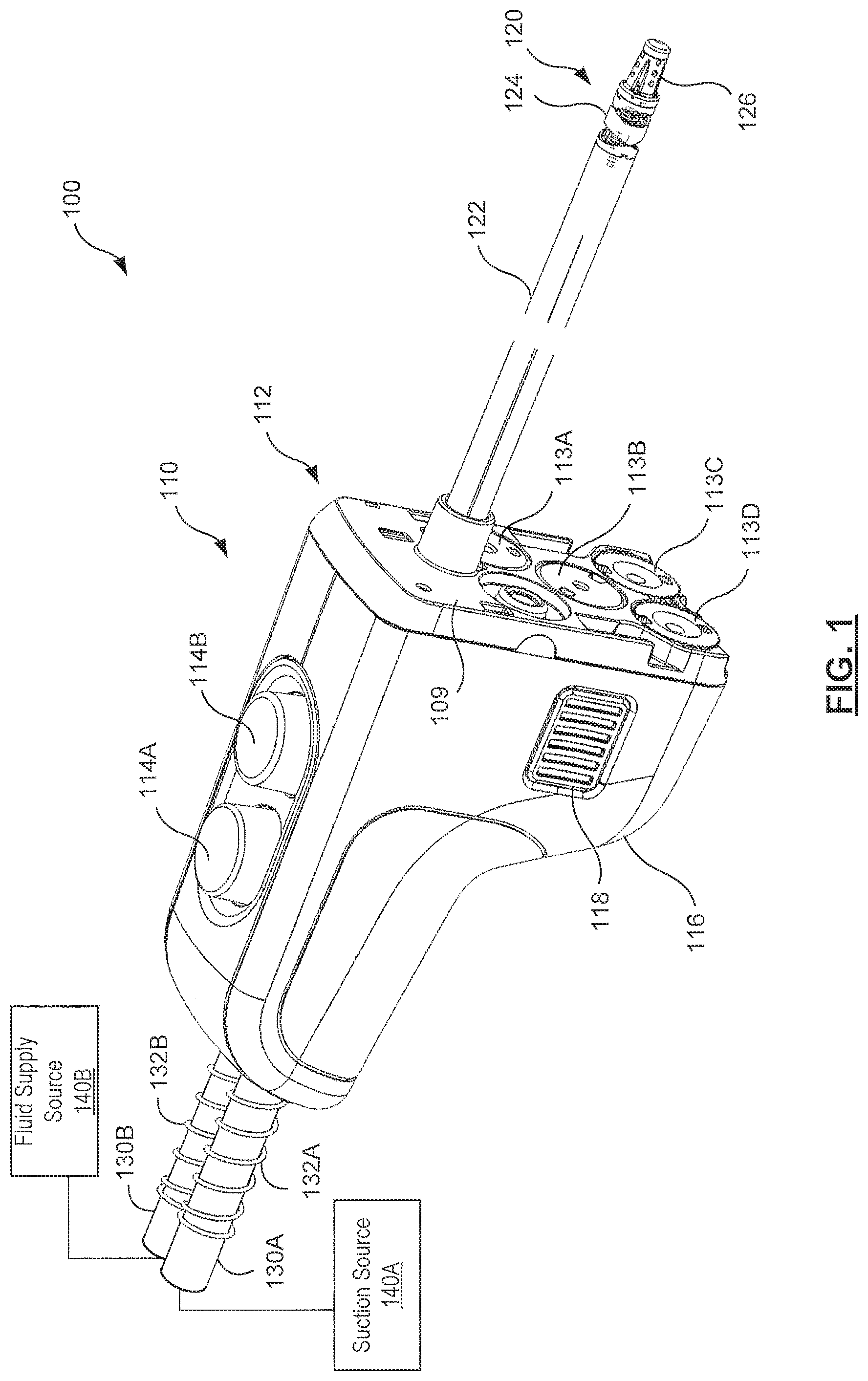
is a perspective view of a medical instrument system according to some embodiments.
is a front elevation view of the medical instrument system of according to some embodiments.
is another front elevation view of the medical instrument system of with an instrument housing removed to show details according to some embodiments.
is a front elevation view of a valve system shown in according to some embodiments.
A is a perspective view of the valve system of according to some embodiments.
B and 5 C are perspective cross-sectional views of the valve system shown in A according to some embodiments.
A is a side view of the valve system according to some embodiments.
B is a cross-sectional side view of the valve system of A according to some embodiments.
A and 7 B are perspective views of valve plungers according to some embodiments.
A and 8 B are side views of the valve plungers of A and 7 B , respectively, showing openings in the valve plungers according to some embodiments.
A and 9 B are additional side views of the valve plungers of A and 7 B , respectively, according to some embodiments.
is a rear perspective view of the valve system, according to some embodiments.
is a rear perspective view of the valve system, according to some embodiments.
Embodiments of the present disclosure and their advantages are best understood by referring to the detailed description that follows. It should be appreciated that like reference numerals are used to identify like elements illustrated in one or more of the figures, wherein showings therein are for purposes of illustrating embodiments of the present disclosure and not for purposes of limiting the same.
DETAILED DESCRIPTION
In the following description, specific details are set forth describing some embodiments consistent with the present disclosure. Numerous specific details are set forth in order to provide a thorough understanding of the embodiments. It will be apparent, however, to one skilled in the art that some embodiments may be practiced without some or all of these specific details. The specific embodiments disclosed herein are meant to be illustrative but not limiting. One skilled in the art may realize other elements that, although not specifically described here, are within the scope and the spirit of this disclosure. In addition, to avoid unnecessary repetition, one or more features shown and described in association with one embodiment may be incorporated into other embodiments unless specifically described otherwise or if the one or more features would make an embodiment non-functional. In some instances well known methods, procedures, components, and circuits have not been described in detail so as not to unnecessarily obscure aspects of the embodiments.
The present application is related to the following U.S. patent applications, all assigned to Intuitive Surgical Operations, Inc. or to Intuitive Surgical, Inc., the contents of which are incorporated herein by reference in their entirety and for all purposes: U.S. patent application Ser. No. 11/341,004 (filed Jan. 27, 2006; entitled “Robotic Surgical Instruments for Irrigation, Aspiration, and Blowing” by Millman et al.); U.S. patent application Ser. No. 11/341,155 (filed Jan. 27, 2006; entitled “Robotic Surgical Instruments with a Fluid Flow Control System for Irrigation, Aspiration, and Blowing” by Millman et al.); U.S. patent application Ser. No. 11/454,359 (filed Jun. 15, 2006; entitled “Robotic Surgical Systems with Fluid Flow Control for Irrigation, Aspiration, and Blowing” by Millman et al.); U.S. patent application Ser. No. 11/454,476 (filed Jun. 15, 2006; entitled “Methods of Fluid How Control with Robotic Surgical Instruments for Irrigation, Aspiration, and Blowing” by Millman et al.); and U.S. patent application Ser. No. 13/446,978 (filed Apr. 13, 2012; entitled “Surgical Instrument with Commonly Actuated Robotic and Manual Features” by Radgowski et al.).
is a perspective view of a medical instrument system 100 according to some embodiments of the present disclosure. The medical instrument system 100 includes a backend mechanism 110 and an elongate instrument portion 120 that is coupled to the backend mechanism 110 at a proximal end of a shaft 122 that forms part of the elongate instrument portion 120 . The instrument portion 120 further includes a wrist mechanism 124 and an end effector 126 . The wrist mechanism 124 is coupled to a distal end of the shaft 122 .
The backend mechanism 110 may include a chassis 112 that has an interface faceplate 109 configured to interface with a teleoperational medical system, according to some embodiments. For example, the chassis 112 may couple to or include gears and interface discs, like exemplary interface discs 113 A and 113 B, configured to connect to an instrument interface on a medical robotic system, such as a da Vinci® model surgical system instrument manipulator arm commercialized by Intuitive Surgical, Inc. of Sunnyvale, Calif. Some embodiments of the mechanism 110 may omit the chassis 112 . Embodiments of the instrument system 100 that include the chassis 112 may provide for both manual and robotically-controlled actuation of the medical instrument system 100 . The backend mechanism 110 further includes a first button 114 A and a second button 114 B, collectively referred to as buttons 114 . As described in more detail herein, the buttons 114 may control suction, ventilation, and/or irrigation functions provided by the medical system 100 . The contact surface of the buttons 114 , i.e. the surface that would generally be in the most contact with the finger of an operator, may be straight, convex, or concave. In some embodiments, the contact surface of the button 114 A is convex, while the contact surface of the button 114 B is concave. In some other embodiments, the contact surface of the button 114 A may be concave, while the contact surface of button 114 E is convex. Additionally, the buttons 114 may have the same color or different colors. For example, whichever button has a convex contact surface may be grey, while the button having the concave surface may be blue. Additional details may be found in U.S. Design patent application Ser. No. 29/581,074, Ser. No. 29/581,071, Ser. No. 29/581,072, and Ser. No. 29/581,073, all of which were filed on Oct. 14, 2016 and are incorporated by reference herein in their entirety.
The backend mechanism 110 includes a rigid housing 116 and includes at least one release mechanism 118 . An operator of the medical system 100 may couple and decouple the medical system 100 to a robotic arm or other robotic manipulator by pressing the release mechanism 118 . Some embodiments may include a release mechanism 118 on the side of the medical system 100 and another release mechanism on the opposite side thereof.
The backend mechanism 110 may be coupled to a console (not explicitly depicted) by conduit such as the first tubing 130 A and second tubing 130 B. An exemplary console may include a suction source 140 A and a liquid or other fluid supply source 140 B. The suction source 140 A provides a fluid suction flow to remove material from an interventional site. The fluid supply source 140 B provides a fluid supply flow, which may be a flow of saline, an inert gas, or another fluid. The tubing 130 A and 130 B, collectively referred to as tubing 130 , may be supported by springs 132 A and 132 B which extend over a distal portion of the tubing 130 A and 130 B, respectively. The springs 132 may provide resistance to prevent collapsing or kinking of the tubing 130 near the junction with the backend mechanism 110 .
is a front elevation view of the medical instrument system 100 of , according to some embodiments. In the view provided by , the tubing 130 is depicted as transparent, such that interior lumens 134 A and 134 B are shown. A proximal end of the lumen 134 A (not shown) may be coupled to a pressurized liquid system that provides a liquid for use at an interventional site. A proximal end of the lumen 134 B (not shown) may be coupled to a system of pressurized air disposed in a console. In some embodiments, the pressurized air system may include a vacuum to facilitate suction or aspiration of material through the lumen 134 B. The pressurized air system may additionally include a pump to facilitate ventilation through the lumen 134 B. As is described in more detail herein, the backend mechanism includes a valve system that couples the lumens 134 A and 134 B to a lumen extending within the shaft 122 to the distal end thereof.
is another front elevation view of the medical instrument system of with an instrument housing removed to show details according to some embodiments. depicts a valve system 200 that, either by robotic control or manual control, selectively couples at least one of the lumens 134 A and 134 B to the shaft 122 of the elongate instrument portion 120 .
is a front elevation view of the valve system 200 shown in according to some embodiments. As shown in , and in other figures, the valve system 200 includes a valve body 202 having flow paths defined therein as well as openings and channels for valve plungers and other features as described herein. The valve body 202 may be formed from a rigid material, such as a rigid plastic material or metal. The buttons 114 are disposed along an axis A 1 . A first tubing coupler 204 is disposed along the axis A 1 . A second tubing coupler 206 is formed in the valve body 202 and oriented along an axis A 2 that forms an angle with the axis A 1 . This angle, referred to as angle θ1, may range from about 10 degrees to about 45 degrees, also depicts actuation members 208 A and 208 B, collectively actuation members 208 , which are coupled to the buttons 114 A and 114 B, respectively. The actuation members 208 A and 208 B may be formed integrally with the buttons 114 A and 114 B in some embodiments. The actuation members 208 may couple the buttons 114 to gears or other drive mechanisms disposed on the chassis 112 of to permit the buttons 114 to be manipulated by an operator via a robotic medical system.
A is a perspective view of the valve system of according to some embodiments. Each of the tubing couplers 204 and 206 may include a stem 210 having a channel 212 formed therein. The stem 210 has a smaller outer diameter than a surrounding portion of the valve body 202 such that the stem 210 and the surrounding portion of the valve body 202 form a recess 214 that is configured to receive the tubing, such as the tubing 130 B as shown in . As shown, the tubing coupler 204 includes a stem 210 A having a channel 212 A. The stem 210 A is surrounded by a recess 214 A. The tubing coupler 206 includes a stem 210 B having a channel 212 B to be formed therein. The stem 210 B is surrounded by a recess 214 B into which the tubing 130 A may be inserted.
B and 5 C are perspective cross-sectional views of the valve system shown in A according to some embodiments, according to the cross-sectional indicators 5 B and 5 C as shown in A . B shows a complete suction flow path 300 extending through the channel 212 A in the valve body 202 . The flow path 300 may extend in a straight line through the valve body 202 as shown in B . As illustrated, the arrow representing the flow path 300 includes a slight jog to facilitate the simultaneous depiction of the flow path 300 and a flow path 302 , another fluid path through which irrigation fluid may flow to the lumen of the shaft 122 as shown in . The flow path 300 may be a straight flow path through the valve body 202 . The flow path 300 may be referred to by component portions 300 A, 300 B, and 3000 . The flow path 300 may include a proximal portion 300 A located proximally from a junction 304 A of the fluid channel 212 A and a valve plunger channel 306 A intersect. The flow path 300 further includes a middle portion 300 B that extends distally from the junction 304 A to a junction 304 B along the flow path 300 . The junction 304 B occurs at the intersection of the fluid channel 212 A and a valve plunger channel 3068 . The additional valve plunger channel 306 A intersects the channel 212 A at a distal position. The portion of the flow path 300 disposed distally from the junction 304 B may be referred to as the distal portion 300 C of the flow path 300 .
The flow path 302 includes a proximal portion 302 A extending through the channel 212 B along the axis A 2 of . The proximal portion 302 A forms a junction with the valve plunger channel 306 B at a bend of the flow path 302 . As illustrated in B and B the bend may have an angle of about 90 degrees. However, the angle of the bend may be different in other embodiments. An intermediate portion 302 B of the flow path 302 extends along the valve plunger channel 306 B to the junction 304 B. Thereafter, the distal portion of the flow path 302 is in common with the distal portion 300 C of the flow path 300 . C shows a perspective cross-section according to the cross-sectional indicator 5 C as shown in A . C shows a cross-section parallel to the central axis of the channel 212 B.
A is a side view of the valve system 200 according to some embodiments. The centers of the channels 212 A and 212 B are separated by distance D 1 . As illustrated, the distance D 1 is about 10 mm. In embodiments of the valve system 200 the distance D 1 a range from about 5 mm to about 30 mm or more. B is a cross-sectional side view of the valve system 200 of A according to some embodiments. The cross-section is obtained along the axis A 1 shown in , through both of the buttons 114 . As shown in cross-section, each of the buttons 114 includes a central recess 115 , labeled as central recess 115 A and 115 B, respectively. The central recess is 115 A and 115 B are respectively coupled to valve plungers 400 A and 400 B. The plungers 400 A and 400 B are disposed within the valve plunger channels 306 A and 306 B, respectively.
The plungers 400 A and 400 B each include at least one O-ring and sealing member. As shown in B , the O-ring 402 A is positioned closer to the sealing member 404 A (both of the valve plunger 400 A) then the O-ring 402 B and the sealing member 404 B (both of the valve plunger 4009 ). Disposed within the valve plunger channels 306 A and 3069 are disposed bias elements 406 A and 4069 , respectively. As shown, the bias elements 406 are coil springs formed from a resilient polymer or metal. A distal end of each of the bias elements 406 A and 406 B contacts a surface of the respective valve plunger 400 A and 400 B. A proximal end of each of the bias elements 406 contacts a proximal end of the valve plunger channels 306 A and 306 B, respectively, to bias the plungers 400 in an extended position. By physically placing sufficient pressure on the buttons 114 A and/or 114 B, an operator may manually activate the valve system 200 , shifting the plungers 400 within their respective channels. Proximal most portions of the plungers 400 are disposed within recesses 408 A and 408 B that have walls configured to maintain alignment of the plungers 400 within the channels 306 A and 306 B, respectively.
A and 7 B are perspective views of valve plungers 400 A and 400 B according to some embodiments. As seen in A , the valve plunger 400 A includes the O-ring 402 A and the sealing member 404 A. At a distal end, the valve plunger includes a protrusion 410 A that is sized for insertion into the recess 115 A of the button 114 A. To ensure alignment of the button 114 A, the protrusion 410 A includes a notch 412 A that interfaces with a corresponding boss disposed on the surface of the recess 115 A. The proximal end of the valve plunger 400 A includes a latch member 414 A. The latch member is configured with two compressible prongs that flex when the valve plunger 400 A is inserted into the channel 306 A. Each of the prongs includes a hook shape that conforms to the dimensions of the recess 408 A shown in B and the service to prevent the valve plunger 400 A from being removed from the channel 306 A. The sealing member 404 A is formed from a material that is less rigid than the material of the plunger 400 A. For example, the sealing member 404 A may be formed from a silicone material, in some embodiments. The sealing member 404 A includes opposing straight edges, of which edge 416 A is shown. The sealing member 404 A further includes opposing curved edges, of which curved edge 418 A is shown. The shape of the edges 416 maintains a seal in the channel 306 A when compressed against the walls thereof. The curved shape of the edges 418 may reduce friction during actuation of the valve. Additionally, the valve plunger 400 A includes an opening 420 A through which fluids (including gases and liquids) and solid material may pass.
B presents a perspective view of the valve plunger 400 B, which includes many of the features described above in connection with the plunger 400 A. Accordingly, the plunger 400 B includes the O-ring 402 B and the sealing member 404 B. The plunger 400 B further includes a protrusion 410 B that is sized and configured for insertion into the recess 115 B of the button 114 B. The protrusion 410 B includes a notch 412 B that corresponds to a boss protruding from the surface of the recess 115 E to maintain alignment of the button 114 E with respect to the valve plunger 400 B. The proximal end of the plunger 400 B includes a latch member 414 B that includes prongs, like the prongs of the latch member 414 A. The valve plunger 400 B further includes an opening 420 B. In some embodiments, the valve plunger 400 A includes an additional O-ring disposed between the latch member 414 A and the sealing member 404 A. Similarly, the valve plunger 400 B may include an additional O-ring disposed between the latch member 414 B and the sealing member 404 B.
A and 8 B are side views of the valve plungers 400 of A and 7 B , respectively, showing openings therein according to some embodiments. The side views of the plungers 400 shown in A and 8 B provide a perspective looking through the openings 420 A and 420 B of the plungers 400 A and 400 B, respectively. While many features of the plungers 400 A and 4009 are of similar or identical dimensions, the openings 420 A and 4209 are substantially different. As shown in A , the opening 420 A has a length L 1 . As illustrated in A , the length L 1 is about 5 mm. In other embodiments of the valve system 200 , the length L 1 of the valve plunger 400 A may be in a range from about 3 mm to about 10 mm or more. The length L 1 is substantially shorter than the length L 2 , which is the length of the opening 420 B in the valve plunger 400 B shown in B . As depicted, the length L 2 may be about 15 mm. Embodiments of the valve plunger 400 B may include an opening 420 B having a length L 2 that ranges from about 5 mm to about 30 mm. The length L 2 of the opening 420 B may be greater than the length L 1 of the opening 420 A, because the opening 420 B is configured to convey material along the flow path 300 as well as along the flow path 302 , whereas the opening 420 A is configured to convey material along the flow path 300 only.
Referring again to B , the valve plungers 400 A and 400 B are positioned in an extended position, caused by the bias elements 406 A and 406 B. When both of the valve plungers 400 A and 400 B are in the extended position as depicted, material is prevented from flowing along either the flow path 300 or the flow path 302 . When the valve plunger 400 A is compressed against the bias element 406 A, whether by manual actuation or a robotic actuation, the opening 420 A becomes aligned with the channel 212 A, permitting material to pass therethrough. The valve plunger 400 B, when in the extended position or in a compressed position, is configured such that the opening 420 B is aligned with the channel 212 A, because the length L 2 is substantially greater in length L 1 . When the valve plunger 400 B is put in a compressed position, whether manually or under robotic actuation, the opening 420 B becomes aligned with the channel 212 B such that the flow path 302 becomes operative. Accordingly, when the valve plunger 400 A is compressed and the valve plunger 400 A is extended, the flow path 300 may freely convey material. When the valve plunger 400 A is extended and the valve plunger 400 B is compressed, the flow path 302 may freely convey material. When both of the plungers are extended, neither the flow path 300 nor the flow path 302 may convey material. When both of the plungers are compressed, both the flow paths 300 and 302 may convey material. The material conveyed may include a gas, liquid, and/or solid material. The flow paths 300 and 302 may convey material in either direction along the flow paths depending upon the pressures provided via the lumens 134 , as shown in .
A and 9 B are additional side views of the valve plungers 400 A and 400 B of A and 7 B , respectively, according to some embodiments. A and 9 B show a different perspective, such that an exterior side wall 422 A of the opening 420 A is shown in A , while an exterior side wall 422 B of the opening 420 B is shown in B .
is a rear perspective view of the valve system 200 , according to some embodiments. provides another view of the interface discs 113 A and 113 B, collectively referred to as interface discs 113 , also shown in . As described herein, the interface discs 113 A and 113 B enable connection to an instrument interface on a medical robotic system to permit control of the valve system 200 by the medical robotic system. As shown each of the interfaces disc 113 may be coupled at a proximal end to a shaft. In some implementations, the interface discs 113 may be integrally formed with the shafts. The interface disc 113 A connects to the proximal end of a shaft 430 A. A gear 432 A may be connected to the distal end of the shaft 430 A. The gear 432 A is positioned such that the teeth of the gear 432 A interact with a row of teeth 434 A formed on a surface of the actuation member 208 A. When the robotic system interacts with the interface disc 113 A, rotating the disc 113 A, the gear 432 A rotates and causes the actuation member 208 A to translate. The translation of the actuation member 208 A may move the valve plunger 400 A in a controlled manner to open or close to couple or decouple the distal portion and middle portion of the flow path 300 . Similarly, the robotic system may rotate the interface disc 113 B, causing the shaft 430 B and gear 432 B to rotate. The rotation of the gear 432 B may cause translation of the actuation member 208 B, which has a row of teeth 434 B that mesh with the teeth of the gear 432 B. In other embodiments of the valve system 200 , other mechanisms may be used to couple a medical robotic system to the actuation members 208 A and 2088 to manipulate the valve plungers 400 A and 400 B.
is another rear perspective view of the valve system 200 , according to some embodiments. provides another view of the valve body 202 , and includes features not explicitly depicted in . shows a review view of the faceplate 109 of the chassis 112 of . In , the view of the shall 430 B is obscured by cable capstans 440 A and 440 B. The cable capstans 440 A and 440 B may be connected to interface discs 113 C and 113 D, respectively. The cable capstans 440 A and 440 B have respective cables 442 A and 442 B wound around capstan shafts with one or more windings. The robotic system may the interface with the discs 113 C and/or 113 D, to manipulate the wrist mechanism 124 and/or the end effector 126 when the medical instrument backend mechanism 110 is connected to the robotic system.
Embodiments of the present disclosure may provide for significant improvements in maintaining the greatest possible suction capacity by providing a straight path for suction and an offset path for irrigation, such as saline or another irrigation material. By lengthening the opening in the valve plunger 400 B relative to the opening in the valve plunger 400 A, the valve plunger 400 B may accommodate both of the straight section path and the offset irrigation path. Such a configuration may provide useful improvements to the performance of suction/irrigation devices.
Aspects of the various embodiments may be combined together. Furthermore, the scope of the present disclosure includes such modifications and adjustments as would be apparent to one of ordinary skill in the art. Accordingly, the scope of the present disclosure is presented with respect to the following claims.
Figures (11)
Citations
This patent cites (20)
- US5490836
- US5722949
- US6375653
- US6419654
- US6652488
- US6808505
- US6958058
- US8241271
- US9259519
- US10155072
- USD874641
- US10722620
- US20030120203
- US20070005002
- US20070156121
- US20090099520
- US20110230823
- US20130046318
- US20180229021
- US20190038816