Method for Producing Denture with High Accuracy of Fitting of Artificial Tooth to Socket
Abstract
A method for manufacturing a denture includes: preparing an artificial tooth and a denture base with a concave socket; applying an adhesive to the concave socket; and embedding the artificial tooth in the concave socket to which the adhesive is applied. A socket groove is defined on an inner surface defining the concave socket. The socket groove extends from a concave bottom surface of the concave socket facing a basal surface of the artificial tooth to a lingual concave side surface of the concave socket. Embedding the artificial tooth in the concave socket includes: forming a discharge hole to discharge the adhesive, the discharge hole being defined at an end of the socket groove on a lingual outer surface of the denture base; and discharging the adhesive from the discharge hole.
Claims (10)
1. A method for manufacturing a denture, comprising: preparing an artificial tooth and a denture base with a concave socket; applying an adhesive to the concave socket; and embedding the artificial tooth in the concave socket to which the adhesive is applied, wherein: a first socket groove is defined on an inner surface defining the concave socket; the first socket groove extends from a concave bottom surface of the concave socket facing a basal surface of the artificial tooth to a lingual concave side surface of the concave socket; a second socket groove extends from the concave bottom surface of the concave socket to a buccal or labial concave side surface of the concave socket; an end of the second socket groove does not reach a buccal or labial outer surface of the denture base; and the embedding the artificial tooth in the concave socket includes: forming a discharge hole to discharge the adhesive, the discharge hole being defined at an end of the first socket groove on a lingual outer surface of the denture base; and discharging the adhesive from the discharge hole.
6. A denture comprising: an artificial tooth; and a denture base with a concave socket in which the artificial tooth is embedded, wherein: a first socket groove is defined on an inner surface defining the concave socket; the first socket groove extends from a concave bottom surface of the concave socket facing a basal surface of the artificial tooth to a lingual concave side surface of the concave socket; a second socket groove extends from the concave bottom surface of the concave socket to a buccal or labial concave side surface of the concave socket; an end of the second socket groove does not reach a buccal or labial outer surface of the denture base; a discharge hole is defined at an end of the first socket groove on a lingual outer surface of the denture base; and the artificial tooth and the denture base are bonded and fixed by an adhesive while the adhesive is in the first socket groove.
Show 8 dependent claims
2. The method according to claim 1 , wherein a cross-sectional area of the first socket groove obtained by cutting in a direction orthogonal to an extending direction of the first socket groove is 0.01 mm 2 or more and 10.0 mm 2 or less.
3. The method according to claim 1 , wherein: a cross-sectional area of the first socket groove obtained by cutting in a direction orthogonal to an extending direction of the first socket groove continuously increases toward a lingual side of the denture base; and an opening area of the discharge hole is greater than the cross-sectional area of the first socket groove in a middle part from the basal surface of the artificial tooth to the concave bottom surface of the concave socket.
4. The method according to claim 1 , wherein: the preparing the artificial tooth and the denture base includes: creating, by a computer, denture base design data of the denture base; and producing, by a producing device, the denture base based on the denture base design data, and the denture base design data is created based on artificial tooth shape data including a first convex portion and a second convex portion corresponding to a shape of the first socket groove and a shape of the second socket groove, respectively.
5. The method according to claim 1 , wherein the artificial tooth includes at least two or more adjacent teeth out of a central incisor, a lateral incisor, a canine, a first premolar, a second premolar, a first molar, and a second molar.
7. The denture according to claim 6 , wherein the artificial tooth includes at least two or more adjacent teeth out of a central incisor, a lateral incisor, a canine, a first premolar, a second premolar, a first molar, and a second molar.
8. The denture according to claim 6 , wherein a cross-sectional area of the first socket groove obtained by cutting in a direction orthogonal to an extending direction of the first socket groove is 0.01 mm 2 or more and 10.0 mm 2 or less.
9. The denture according to claim 8 , wherein the artificial tooth includes at least two or more adjacent teeth out of a central incisor, a lateral incisor, a canine, a first premolar, a second premolar, a first molar, and a second molar.
10. The denture according to claim 6 , wherein: a cross-sectional area of the first socket groove obtained by cutting in a direction orthogonal to an extending direction of the first socket groove continuously increases toward a lingual side of the denture base; and an opening area of the discharge hole is greater than the cross-sectional area of the first socket groove in a middle part from the basal surface of the artificial tooth to the concave bottom surface of the concave socket.
Full Description
Show full text →
CROSS-REFERENCE TO RELATED APPLICATIONS
This application claims priority to Japanese Patent application No. 2020-160671, filed Sep. 25, 2020, and Japanese Patent application No. 2021-089365, filed May 27, 2021, the disclosure of which is incorporated herein by reference in the entirety.
BACKGROUND OF THE INVENTION
1. Field of the Invention
The present invention relates to a denture and a method for manufacturing a plate denture and more particularly to a method for producing a denture based on a computer-aided design/manufacturing method (CAD/CAM).
2. Description of the Related Art
WO 2015/125573 discloses an artificial tooth having a shape corresponding to a denture base designed on CAD based on three-dimensional data before machining. In the artificial tooth described in WO 2015/125573, a means for restricting rotation around a tooth axis is disposed in a portion to be in contact with the denture base, and the restricting means has a shape not engaged with the denture base in a tooth axis direction.
Japanese Patent Publication No. 2018-102853, the floor portion discloses a method for manufacturing a plate denture including: a denture base having a base, multiple sockets formed adjacently in the base and in which artificial teeth are arranged, and a first notch portion disposed in a partition wall between the multiple sockets to partially reduce the height of the partition wall; and artificial teeth fixed to the socket of the denture base.
WO 2015/194449 discloses an artificial tooth having a convex portion to be embedded in an internal corner portion of a concave portion of a denture base, wherein the convex portion has a form forming a predetermined gap from the internal corner portion without coming into contact with the internal corner portion when embedded in the internal corner portion.
WO 2018/069317 discloses a method for producing a denture including a denture base and at least two artificial teeth arranged on the denture base.
SUMMARY OF THE INVENTION
The problem to be solved by the present invention is to provide a denture improved in accuracy of fitting of an artificial tooth to a socket.
The present invention solving the problems will be described below. For easy understanding, reference numerals attached to the description and drawings are also described in parentheses; however, the present invention is not limited thereto.
An aspect of the present invention provides a method for manufacturing a denture according to comprising:
•
• preparing an artificial tooth ( 1 , 1 A) and a denture base ( 3 , 3 A) provided with a concave socket ( 2 , 2 A) in which the artificial tooth ( 1 , 1 A) is embedded; • applying an adhesive ( 12 ) to the socket ( 2 , 2 A); and • embedding the artificial tooth ( 1 , 1 A) in the socket ( 2 , 2 A) to which the adhesive ( 12 ) is applied, wherein • one or more grooves ( 9 , 10 , 13 , 9 A, 10 A) are provided on at least one of a surface ( 5 ) of the artificial tooth ( 1 , 1 A) on the side embedded in the socket ( 2 , 2 A) and an inner surface ( 6 ) defining the socket ( 2 , 2 A), wherein • the one or more grooves ( 9 , 10 , 13 , 9 A, 10 A) include a groove ( 9 , 9 A, 13 ) extending to the lingual side, and wherein • the embedding the artificial tooth ( 1 , 1 A) in the socket ( 2 , 2 A) includes • forming a discharge hole ( 11 , 11 A) exposing an end ( 9 a , 9 b ) side of the groove ( 9 , 9 A, 13 ) extending to the lingual side from the denture base ( 3 , 3 A) to discharge the adhesive ( 12 ), and • discharging the adhesive ( 12 ) from the discharge hole ( 11 , 11 A).
An aspect of the present invention provides a denture comprising:
•
• an artificial tooth ( 1 , 1 A); and • a denture base ( 3 , 3 A) provided with a concave socket ( 2 , 2 A) in which the artificial tooth ( 1 , 1 A) is embedded, wherein • one or more grooves ( 9 , 10 , 13 , 9 A, 10 A) are provided on at least one of a surface ( 5 ) of the artificial tooth ( 1 , 1 A) on the side embedded in the socket ( 2 , 2 A) and an inner surface ( 6 ) defining the socket ( 2 , 2 A), wherein • the one or more grooves ( 9 , 10 , 13 , 9 A, 10 A) include a groove ( 9 , 9 A, 13 ) extending to the lingual side, wherein • an end ( 9 a , 9 b ) side of the groove ( 9 , 9 A, 13 ) extending to the lingual side is exposed from the denture base ( 3 , 3 A), and wherein • the artificial tooth ( 1 , 1 A) and the denture base ( 3 , 3 A) are bonded and fixed by an adhesive. ( 12 ) while the adhesive ( 12 ) is disposed in the one or more grooves ( 9 , 10 , 13 , 9 A, 10 A).
The present invention can provide the denture improved in accuracy of fitting of an artificial tooth to a socket.
BRIEF DESCRIPTION OF THE DRAWINGS
is a frontal cross-sectional view of a denture (first embodiment, representative example);
is a perspective view of an artificial tooth (second embodiment);
a is an occlusal surface view on the right side of an artificial tooth portion of a mandibular denture;
b is a basal surface view of an artificial tooth of a mandibular canine (third embodiment);
is a frontal cross-sectional view of a denture (known technical form);
is a frontal cross-sectional view of a denture (fourth embodiment);
is a frontal cross-sectional view of a denture (fifth embodiment);
is a basal surface view of coupled artificial teeth;
a is a conceptual diagram of a denture design process program.
b is a conceptual diagram of the denture design process program.
c is a conceptual diagram of the denture design process program.
d is a conceptual diagram of the denture design process program.
e is a conceptual diagram of the denture design process program.
f is a conceptual diagram of the denture design process program.
a is a conceptual diagram of the denture design process program.
b is a conceptual diagram of the denture design process program.
c is a conceptual diagram of the denture design process program.
d is a conceptual diagram of the denture design process program.
e is a conceptual diagram of the denture design process program.
f is a conceptual diagram of the denture design process program.
is a diagram showing an example of a flowchart of a method for manufacturing a denture.
is a conceptual diagram for explaining an example of a process of forming a discharge hole.
is a conceptual diagram for explaining an example of a process of discharging an adhesive from the discharge hole.
is a conceptual diagram for explaining an example of a process of forming a discharge hole.
is a conceptual diagram for explaining an example of a process of discharging an adhesive from the discharge hole.
DESCRIPTION OF THE PREFERRED EMBODIMENTS
Background to Present Disclosure
In recent, years, in a method of producing a plate denture starting to be put into practical use, a denture is designed on a computer using CAD/CAM technology; a denture base excluding a portion for embedding an artificial tooth is produced by a method such as cutting by an NC machine tool or 3D printing; a ready-made artificial tooth or an artificial tooth manufactured by a method such as 3D printing is coupled by using an adhesive to an artificial tooth embedding portion (referred to as a socket) of the denture base. Generally, in consideration of an error in fitting between the denture base and the artificial tooth, the socket is often provided with a dimension larger than the shape of the artificial tooth so that a gap (offset) is formed between the socket and the artificial tooth. However, in reality, it is difficult to accurately embed the artificial tooth in the socket at a position designed on a computer due to influences of an amount and a viscosity of applied adhesive. Additionally, since an operation of embedding and bonding artificial teeth one by one in the socket is manually performed, the thickness of the adhesive tends to vary, which greatly affects establishment of an occlusal contact relationship of the entire denture and also impairs labor saving.
In other words, even if a denture can be designed in an appropriate occlusal state on a computer, an occlusal relationship needs to be adjusted by grinding due to an influence of an error that actually occurs, which is a major cause of impairing labor saving by digitization and also a major obstacle to the production of highly accurate dentures.
In this operation, it is difficult to control the application amount of the adhesive, and a difference in experience is likely to occur. If the amount of the adhesive is large, the adhesive leaks to a surface of the artificial tooth or a polished surface of the denture base when the artificial tooth is embedded. This not only impairs labor saving due to an operation of wiping off the leaked adhesive and a complicated work such as cutting and polishing in some cases, but also impairs the aesthetics of the artificial tooth, the appearance, of the denture, and the original design shape.
In WO 2015/125573, a restricting means having a shape not engaging with a denture base in a tooth axis direction is disposed in a portion to be in contact with the denture base, and the restricting means prevents an artificial tooth from moving in a rotation direction around the tooth axis. However, it is difficult to control uplifting of the artificial tooth in a vertical direction due to the thickness of the adhesive.
In Japanese Patent Publication No. 2018-102853, in a method disclosed as a method of controlling leakage of an adhesive from between a socket and an artificial tooth, a partition wall disposed between multiple sockets formed adjacent to each other and in which artificial teeth are arranged is designed to be partially made lower in the denture base. However, if the partition wall of the sockets is made lower, the bond strength between the artificial tooth and the denture base cannot be supplemented, and the artificial teeth may fall off due to an occlusal contact between the artificial teeth without food in the oral cavity or an occlusal pressure and an impact of crushing food while food is interposed during eating.
WO 2015/194449 discloses an artificial tooth that can reliably be attached to a denture base when artificial teeth are arranged on the denture base designed and formed by CAD/CAM. However, designing the convex portion of the artificial tooth to be embedded according to the internal corner portion of the concave portion of the denture base and separately shaping the artificial tooth may require a highly accurate and complicated process. Additionally, in the case of a ready-made artificial tooth, this method is difficult to use since the shape of the internal corner portion is determined before the design of the denture base. Furthermore, since the influence of the application amount of the adhesive is not taken into consideration, it is difficult to ensure the stable accuracy of fitting with the artificial tooth.
WO 2018/069317 discloses a denture producing method including producing at least two artificial teeth in a state where a common arrangement support for artificial teeth is connected to at least two artificial teeth. The denture producing method described in WO 2013/069317 is intended to improve the fitting accuracy between a plurality of artificial teeth and sockets; however, since the common support is disposed in a place responsible for a morphologically important function such as the lip surface and the occlusal surface appearing to the outside, a cutting mark remain due to removal of the support, so that a very complicated work such as restoration of surface characteristics and adjustment of occlusal relationship may be performed.
Therefore, to solve the problems, the present inventors conducted study to enable more efficient work, achieve high accuracy of fitting of an artificial tooth to a socket, and establish a high-precision occlusal contact relationship between the upper and lower jaws, without impairing the merit of labor saving in the computer-aided (CAD/CAM) denture production. More specifically, the present inventors conducted study on a method of producing a denture including filling the adhesive evenly in the socket and suppressing a leakage to the outside of the socket to a requisite minimum to eliminate extra adjustment work so that the denture is hardly affected by the application amount of the adhesive.
As a result, the including filling the adhesive evenly in the socket and suppressing a leakage to the outside of the socket to a requisite minimum to eliminate extra adjustment work so that the denture is hardly affected by the application amount of the adhesive. In other words, the present inventors conceived the method of producing a denture enabling more efficient work, achieving high accuracy of fitting of an artificial tooth to a socket, and establishing a high-precision occlusal contact relationship between the upper and lower jaws, without impairing the merit of labor saving in the computer-aided (CAD/CAM) denture production.
A method for manufacturing a denture according to a first aspect of the present invention comprises:
•
• preparing an artificial tooth ( 1 , 1 A) and a denture base ( 3 , 3 A) provided with a concave socket ( 2 , 2 A) in which the artificial tooth ( 1 , 1 A) is embedded; • applying an adhesive ( 12 ) to the socket ( 2 , 2 A); and • embedding the artificial tooth ( 1 , 1 A) in the socket ( 2 , 2 A) to which the adhesive ( 12 ) is applied, • one or more grooves ( 9 , 10 , 13 , 9 A, 10 A) are provided on at least one of a surface ( 5 ) of the artificial tooth ( 1 , 1 A) on the side embedded in the socket ( 2 , 2 A) and an inner surface ( 6 ) defining the socket ( 2 , 2 A), • the one or more grooves ( 9 , 10 , 13 , 9 A, 10 A) include a groove ( 9 , 9 A, 13 ) extending to the lingual side, and • the embedding the artificial tooth ( 1 , 1 A) in the socket ( 2 , 2 A) includes • forming a discharge hole ( 11 , 11 A) exposing an end ( 9 a , 9 b ) side of the groove ( 9 , 9 A, 13 ) extending to the lingual side from the denture base ( 3 , 3 A) to discharge the adhesive ( 12 ), and • discharging the adhesive ( 12 ) from the discharge hole ( 11 , 11 A).
In the method for manufacturing a denture according to a second aspect of the present invention,
•
• the preparing the artificial tooth ( 1 , 1 A) and the denture base ( 3 , 3 A) may include preparing the artificial tooth ( 1 ) provided with a first groove ( 9 ) and a second groove ( 10 ), the first groove ( 9 ) extending from a basal surface ( 7 ) to a lingual side surface ( 5 a ) of the artificial tooth ( 1 ), and the second groove ( 10 ) extending from the basal surface ( 7 ) to a buccal or labial side surface ( 5 b ) of the artificial tooth ( 1 ), • an end ( 9 a ) of the first groove ( 9 ) extending on the lingual side surface ( 5 a ) may be located on a crown side relative to a cervical line ( 8 ) on the lingual side of the artificial tooth ( 1 ), and • an end ( 10 b ) of the second groove ( 10 ) extending on the buccal or labial side surface ( 5 b ) may be located on a root side relative to the cervical line ( 8 ) on the buccal or labial side of the artificial tooth ( 1 ).
In the method for producing a denture according to a third aspect of the present invention,
•
• the preparing the artificial tooth ( 1 , 1 A) and the denture base ( 3 , 3 A) may include preparing the denture base ( 3 A) provided with a third groove ( 9 A) and a fourth groove ( 10 A), the third groove ( 9 A) extending from a concave bottom surface ( 6 a ) of the socket ( 2 A) facing the basal surface ( 7 ) of the artificial tooth ( 1 , 1 A) to a lingual concave side surface ( 6 b ), and a fourth groove ( 10 A) extending from the concave bottom surface ( 6 a ) of the socket ( 2 A) to a buccal or labial concave side surface ( 6 c ), • an end ( 9 b ) of the third groove ( 9 A) extending from the lingual concave side surface ( 6 b ) may reach a lingual outer surface ( 6 d ) of the denture base ( 3 A), and • an end ( 10 b ) of the fourth groove ( 10 A) extending from the buccal or labial concave side surface ( 6 c ) may not reach a buccal or labial outer surface ( 6 e ) of the denture base ( 3 A).
In the method for manufacturing a denture according to a fourth aspect of the present invention,
•
• a cross-sectional area of the one or more grooves ( 9 , 10 , 13 , 9 A, 10 A) obtained by cutting in a direction orthogonal to an extending direction of the one or more grooves ( 9 , 10 , 13 , 9 A, 10 A) may be 0.01 mm 2 or more and 10.0 mm 2 or less.
In the method for manufacturing a denture according to a fifth aspect of the present invention, the cross-sectional area of the one or more grooves ( 9 , 10 , 13 , 9 A, 10 A) obtained by cutting in a direction orthogonal to an extending direction of the one or more grooves ( 9 , 10 , 13 , 9 A, 10 A) may increase toward the lingual side.
In the method for manufacturing a denture according to a sixth aspect of the present invention,
•
• the preparing the artificial tooth ( 1 , 1 A) and the denture base ( 3 , 3 A) may include • creating, by a computer, denture base design data (D 3 ) of the denture base ( 3 ), and • producing, by a producing device, the denture base ( 3 ) based on the denture base design data (D 3 ), and • when the denture base design data (D 3 ) is created, the denture base design data (D 3 ) provided with a concave socket (D 2 ) may be created based on the artificial tooth shape data (D 1 ) which is not provided with the first groove ( 9 ) and the second groove ( 10 ).
In the method for manufacturing a denture according to a seventh aspect of the present invention,
•
• the preparing the artificial tooth ( 1 , 1 A) and the denture base ( 3 , 3 A) may include • creating, by a computer, denture base design data (D 3 A) of the denture base ( 3 A), and • producing, by a producing device, the denture base ( 3 A) based on the denture base design data (D 3 A), and • when the denture base design data (D 3 A) is created, the denture base design data (D 3 A) provided with a concave socket (D 2 ) having the third groove ( 9 A) and the fourth groove ( 10 A) formed on an inner surface may be created based on the artificial tooth shape data (D 1 A) including a first convex portion (D 15 ) and a second convex portion (D 16 ) corresponding to the shapes of the third groove ( 9 A) and the fourth groove ( 10 A).
In the method for manufacturing a denture according to an eighth aspect of the present invention,
•
• the artificial tooth ( 1 , 1 A) may include at least two or more adjacent teeth out of a central incisor, a lateral incisor, a canine, a first premolar, a second premolar, a first molar, and a second molar.
In the method for manufacturing a denture according to a ninth aspect of the present invention,
•
• the basal surface ( 7 ) of the artificial tooth ( 1 ) may be provided with a continuous groove ( 14 ) continuously provided across at least two or more adjacent teeth, • the one or more grooves ( 9 , 10 , 13 ) may be provided on the surface ( 5 ) of the artificial tooth ( 1 ), and • the continuous groove ( 14 ) may communicate with the one or more grooves ( 9 , 10 , 13 ).
A denture according to a tenth aspect of the present invention comprises:
•
• an artificial tooth ( 1 , 1 A); and • a denture base ( 3 , 3 A) provided with a concave socket ( 2 , 2 A) in which the artificial tooth ( 1 , 1 A) is embedded, • one or more grooves ( 9 , 10 , 13 , 9 A, 10 A) are provided on at least one of a surface ( 5 ) of the artificial tooth ( 1 , 1 A) on the side embedded in the socket ( 2 , 2 A) and an inner surface ( 6 ) defining the socket ( 2 , 2 A), • the one or more grooves ( 9 , 10 , 13 , 9 A, 10 A) include a groove ( 9 , 9 A, 13 ) extending to the lingual side, • an end ( 9 a , 9 b ) side of the groove ( 9 , 9 A, 13 ) extending to the lingual side is exposed from the denture base ( 3 , 3 A), and • the artificial tooth ( 1 , 1 A) and the denture base ( 3 , 3 A) are bonded and fixed by an adhesive ( 12 ) while the adhesive ( 12 ) is disposed in the one or more grooves ( 9 , 10 , 13 , 9 A, 10 A).
In the denture of an eleventh aspect of the present invention,
•
• the one or more grooves ( 9 , 10 , 13 ) may include a first groove ( 9 ) and a second groove ( 10 ), the groove ( 9 ) extending from a basal surface ( 7 ) to a lingual side surface ( 5 a ) of the artificial tooth ( 1 ), and the second groove ( 10 ) extending from the basal surface ( 7 ) to a buccal or labial side surface ( 5 b ) of the artificial tooth ( 1 ), • an end ( 9 a ) of the first groove ( 9 ) extending on the lingual side surface ( 5 a ) may be located on a crown side relative to a cervical line ( 8 ) on the lingual side of the artificial tooth ( 1 ), and • an end ( 10 b ) of the second groove ( 10 ) extending on the buccal or labial, side surface ( 5 b ) may be located on a root side relative to the cervical line ( 8 ) on the buccal or labial side of the artificial tooth ( 1 ).
In the denture of a twelfth aspect of the present invention,
•
• the one or more grooves ( 9 , 10 , 13 ) may include a third groove ( 9 A) and a fourth groove ( 10 A), the third groove ( 9 A) extending from a concave bottom surface ( 6 a ) of the socket ( 2 A) facing the basal surface ( 7 ) of the artificial tooth ( 1 , 1 A) to a lingual concave side surface ( 6 b ), and the fourth groove ( 10 A) extending from the concave bottom surface ( 6 a ) of the socket ( 2 A) to a buccal or labial concave side surface ( 6 c ), • an end ( 9 b ) of the third groove ( 9 A) extending from the lingual concave side surface ( 6 b ) may reach a lingual outer surface ( 6 d ) of the denture base ( 3 A), and • an end ( 10 b ) of the fourth groove ( 10 A) extending from the buccal or labial concave side surface ( 6 c ) may not reach a buccal or labial outer surface ( 6 e ) of the denture base ( 3 A).
In the denture of a thirteenth aspect of the present invention,
•
• the artificial tooth ( 1 , 1 A) may include at least two or more adjacent teeth out of a central incisor, a lateral incisor, a canine, a first premolar, a second premolar, a first molar, and a second molar.
In the denture of a fourteenth aspect of the present invention,
•
• the basal surface ( 7 ) of the artificial tooth ( 1 ) may be provided with a continuous groove ( 14 ) continuously provided across at least two or more adjacent teeth, • the one or more grooves ( 9 , 10 , 13 ) may be provided on the surface ( 5 ) of the artificial tooth ( 1 ), • the continuous groove ( 14 ) may communicate with the one or more grooves ( 9 , 10 , 13 ), and • the adhesive ( 12 ) may be disposed in the continuous groove ( 14 ).
The present invention will now be described in detail with reference to the drawings. The drawings show the most effective examples for easy understanding; however, the present invention is not limited thereto.
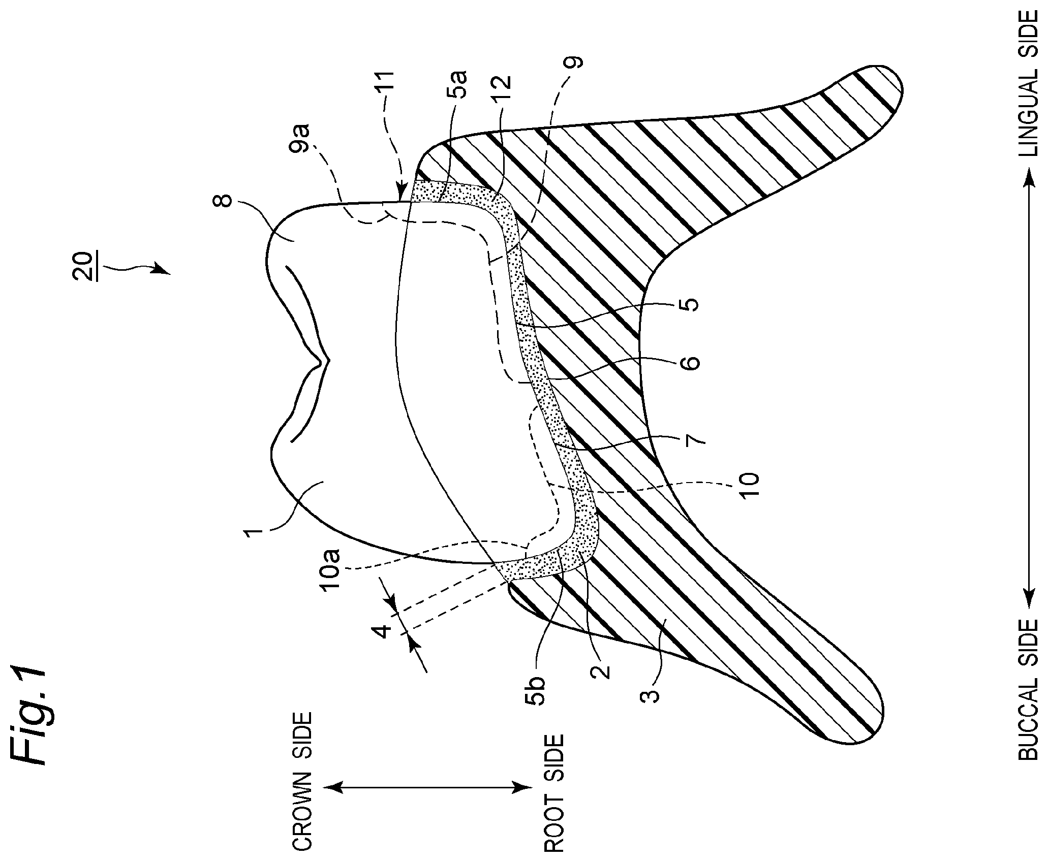
shows a frontal cross-sectional view of a typical example of a denture 20 . The denture 20 includes an artificial tooth 1 and a denture base 3 provided with a socket 2 into which the artificial tooth 1 is embedded. The socket 2 is provided with a space 4 for an adhesive 12 . The space 4 is a gap disposed in consideration of a fitting tolerance between the artificial tooth 1 and the denture base 3 . In the figure, the left side of the denture 20 shows the buccal side, and the right side shows the lingual side. In the example shown in , a molar tooth is described as the artificial tooth 1 . The material of the adhesive 12 is not particularly limited and may be known adhesives or acrylic-based autopolymerizing resins, and if the denture base 3 is shaped with a 3D printer etc. liquid materials thereof can also be used.
In the denture 20 , a groove 9 extending from a basal surface 7 of the artificial tooth 1 to above a cervical line 8 on the lingual side and a groove 10 extending from the basal surface 7 of the artificial tooth 1 to below the cervical line 8 on the labial or buccal side is disposed on a surface 5 of an embedded portion of the artificial tooth 1 . However, the present invention is not limited thereto, and the grooves 9 , 10 may be disposed on an inner surface 6 of the socket 2 of the denture base 3 or on both. In this description, the groove 9 may be referred to as a “first groove 9 ”, and the groove 10 may be referred to as a “second groove 10 ”.
The surface 5 of the embedded portion of the artificial tooth 1 means a surface of the artificial tooth 1 on the side arranged in the socket 2 . For example, the surface 5 is a surface of the artificial tooth 1 facing the inner surface 6 of the socket 2 and has the basal surface 7 and side surfaces 5 a , 5 b of the artificial tooth 1 when the denture 20 is viewed from the side. The side surface 5 a is the lingual side surface of the artificial tooth 1 , and the side surface 5 b is the buccal side surface of the artificial tooth 1 . The cervical line 8 means a boundary line between a crown and a root of the artificial tooth 1 . For example, the cervical line 8 may indicate the depth at which the artificial tooth 1 is embedded in the socket 2 .
The shape, material, and manufacturing means of the artificial tooth 1 are not particularly limited, and those of a known technique may be used. For example, the artificial tooth may be a ready-made artificial tooth made of acrylic resin mass-produced by molds, or an artificial tooth designed into a shape meeting the individual needs of patients by using dental CAD/CAM technology and subjected to cutting or laminate molding. The shape of the artificial tooth 1 may be formed by single teeth such that respective teeth are independent, or two or more teeth may be coupled. For example, the artificial tooth 1 includes at least one of a central incisor, a lateral incisor, a canine, a first premolar, a second premolar, a first molar, and a second molar.
The denture base 3 is a base on which the artificial tooth 1 is arranged. The socket 2 for embedding the artificial tooth 1 is formed in the denture base 3 . The material of the denture base 3 is not particularly limited, and those of a known technique such as PMMA (polymethylmethacrylate), PC (polycarbonate), and PA (polyamide) may be used.
The socket 2 is a concave portion recessed on the surface of the denture base 3 . A base of the artificial tooth 1 is inserted in the socket 2 . The base of the artificial tooth 1 is a portion of the artificial tooth 1 on the basal surface 7 side, and is a portion bonded to the denture base 3 . The socket 2 is formed in a concave shape in accordance with the outer shape of the base of the artificial tooth 1 . Therefore, the socket 2 is formed in a recessed manner in a concave shape surrounding at least a part of the base of the artificial tooth 1 . The socket 2 is formed along the arrangement direction of the artificial teeth 1 .
The artificial tooth 1 is bonded and fixed to the denture base 3 by the adhesive 12 . The adhesive 12 is disposed in the space 4 between the surface 5 of the artificial tooth 1 and the inner surface 6 of the socket 2 .
In the example shown in , the grooves 9 , 10 are provided on the basal surface 7 side of the artificial tooth 1 . The groove 9 is formed on the basal surface 7 of the artificial tooth 1 and the lingual side surface 5 a of the artificial tooth 1 . Specifically, the groove 9 extends from near the center of the artificial tooth 1 toward the lingual side on the basal surface 7 and extends on the lingual side surface 5 a of the artificial tooth 1 toward the cusp side (crown side) when viewed from the side of the artificial tooth 1 . For example, the groove 9 is linearly formed from near the center of the artificial tooth 1 toward the lingual side. An end 9 a side of the groove 9 formed on the lingual side surface 5 a of the artificial tooth 1 is exposed from the denture base 3 . Specifically, the end 9 a of the groove 9 formed on the lingual side surface 5 a of the artificial tooth 1 is located on the crown side of the artificial tooth 1 relative to the cervical line 8 . The cervical line 8 is a line indicative of the height of the artificial tooth 1 embedded in the socket 2 . Therefore, the distance from the basal surface 7 of the artificial tooth 1 to the end 9 a of the groove 9 on the lingual side surface 5 a of the artificial tooth 1 is greater than the depth of the socket 2 . As a result, while the artificial tooth 1 is embedded in the socket 2 , the end 9 a side of the groove 9 is exposed from the denture base 3 to form the discharge hole 11 . When the artificial tooth 1 is adhesively fixed to the socket 2 , the discharge hole 11 discharges the excess adhesive 12 disposed between the surface 5 of the artificial tooth 1 and the inner surface 6 of the socket 2 . The size of the discharge hole 11 is not particularly limited and, however, has an opening area of 0.01 mm 2 or more and 10.0 mm 2 or less, preferably 0.1 mm 2 or more and 4.0 mm 2 or less.
The groove 10 is formed on the basal surface 7 of the artificial tooth 1 and the buccal side surface 5 b of the artificial tooth 1 . Specifically, the groove 10 extends from the center of the artificial tooth 1 toward the buccal side on the basal surface 7 and extends on the buccal side surface 5 b of the artificial tooth toward the cusp side (the crown side), when viewed from the side of the artificial tooth 1 . For example, the groove 10 is linearly formed from near the center of the artificial tooth 1 toward the buccal side. The groove 10 is not exposed from the denture base 3 . Specifically, an end 10 a of the groove 10 formed on the buccal side surface 5 b of the artificial tooth 1 is located on the root side of the artificial tooth 1 relative to the cervical line 8 and is not located on the crown side of the artificial tooth 1 relative to the cervical line 8 . Therefore, the distance from the basal surface 7 of the artificial tooth 1 to the end 10 a of the groove 10 on the buccal side surface 5 b of the artificial tooth 1 is less than the depth of the socket 2 . As a result, the groove 10 is not exposed from the denture base 3 while the artificial, tooth 1 is embedded in the socket 2 .
Cross-sectional areas of the groove 9 and the groove 10 are 0.01 mm 2 or more and 10.0 mm 2 or less, preferably 0.1 mm 2 or more and 4.0 mm 2 or less. The cross-sectional areas of the groove 9 and the groove 10 mean areas of cross sections obtained by cutting in the direction orthogonal to the extending direction of the groove 9 and the groove 10 . The shape of the cross section of the groove 9 and the groove 10 is not particularly limited and may be, for example, a semicircle, an ellipse, a trapezoid, or a triangle. The grooves 9 , 10 allow the adhesive 12 to easily flow in the lingual direction, or in the labial or buccal direction, so that the filling amount can be controlled without excess or deficiency. Although the grooves 9 , 10 are linearly formed in the example described above, the present invention is not limited thereto. For example, the grooves 9 , 10 may be formed in a curved shape. The cross-sectional areas of the groove 9 and the groove 10 may vary in the extending direction of the groove 9 and the groove 10 . For example, the cross-sectional areas of the groove 9 and the groove 10 may increase from the buccal side to the lingual side. Alternatively, the cross-sectional areas of the groove 9 and the groove 10 may be constant.
In the example shown in , to show the basic requirements, the groove 9 and the groove 10 are shown as respective independent grooves; however, the present invention is not limited thereto. As described later with reference to , one groove may be formed to extend from above the cervical line 8 on the lingual side to below the cervical line 8 on the labial or buccal side via the basal surface 7 . Therefore, the groove 9 and the groove 10 may be connected to form one groove.
shows an example of the artificial tooth 1 in the denture 20 . In the example shown in , the artificial tooth 1 is a canine. In the example shown in , the groove 9 extending from the basal surface 7 to above the cervical line 8 on the lingual side and the groove 10 extending from the basal surface 7 to below the cervical line 8 on the labial or buccal side are formed by one groove 13 . Therefore, the groove 13 extends from above the cervical line 8 on the lingual side to below the cervical line 8 on the labial or buccal side via the basal surface 7 . However, the present invention is not limited thereto and may be respective independent grooves.
Explaining in detail, in the example shown in , the one groove 13 is formed by integrally forming the groove 9 and the groove 10 . The groove 13 is continuously disposed on the basal surface 7 of the artificial tooth 1 from the labial side surface 5 b toward the lingual side surface 5 a of the artificial tooth 1 . For example, the groove 13 is linearly formed from the labial side surface 5 b to the lingual side surface 5 a of the artificial tooth 1 on the basal surface 7 of the artificial tooth 1 . The cross-sectional area of the groove 13 varies from the labial side surface 5 b toward the lingual side surface 5 a of the artificial tooth 1 . In this case, the cross-sectional area of the groove 13 means an area of the cross section obtained by cutting in the direction orthogonal to the extending direction of the groove 13 . For example, the cross-sectional area of the groove 13 may continuously be increased from the labial side surface 5 b toward the lingual side surface 5 a of the artificial tooth 1 or may be increased stepwise. This makes it easier for the adhesive 12 to flow to the lingual side. The cross-sectional area of the groove 13 is 0.01 mm 2 or more and 10.0 mm 2 or less, preferably 0.1 mm 2 or more and 4.0 mm 2 or less. The shape of the cross section of the groove 13 is not particularly limited, and may be, for example, a semicircle, an ellipse, a trapezoid, or a triangle.
a is an occlusal surface view of the right side of an artificial tooth portion of an exemplary mandibular denture 20 A, and b shows an enlarged view of a mandibular canine TL 3 shown in a Z 1 portion of a as viewed from the basal surface 7 side. The mandibular denture 20 A shown in a has a mandibular central incisor TL 1 , a mandibular lateral incisor TL 2 , a mandibular canine TL 3 , a mandibular first premolar TL 4 , a mandibular second premolar TL 5 , a mandibular first molar TL 6 , and a mandibular second molar TL 7 on each of the left and right sides. The Mandibular central incisor TL 1 , the mandibular lateral incisor TL 2 , the mandibular canine TL 3 , the mandibular first premolar TL 4 , the mandibular second premolar TL 5 , the mandibular first molar TL 6 , and the mandibular second molar TL 7 are arranged in a tooth arch shape, i.e., in a U shape. The mandibular central incisor TL 1 , the mandibular lateral incisor TL 2 , and the mandibular canine TL 3 are included in a front tooth, and the mandibular first premolar TL 4 , the mandibular second premolar TL 5 , the mandibular first molar TL 6 , and the mandibular second molar TL 7 are included in a molar tooth.
As shown in a , the labial side refers to the side where the front tooth appears to the outside when the mouth is opened, and the buccal side refers to the side where the molar tooth contacts the buccal mucosa in the oral cavity, both of which refer to the outside of the dental arch. The lingual side is the side coming into contact with the tongue and refers to the inside the dental arch. In this description, for convenience, to clearly define the range of the grooves 9 , 10 provided in the artificial tooth 1 or the socket 2 in the extending direction, the labial side refers to the entire region on the side appearing to the outside at the time of opening of the mouth when an incisal edge dividing the front tooth into two in the labial-lingual direction is defined as a boundary line L 1 . The buccal side refers to the region on the side appearing to the outside at the time of opening of the mouth when an occlusal edge connecting the buccal cusps of the molars is defined as a boundary line L 2 . The lingual side refers to the region on the side bring into contact with the tongue from the boundary lines L 1 , L 2 of the front tooth and the molar tooth. Although the side corresponding to the lingual side of the lower jaw is usually referred to as the palatal side in the upper jaw, this side is also referred to as the lingual side in this description.
In the example of the mandibular canine TL 3 of b , the groove 9 on the lingual side of the mandibular canine TL 3 is provided on the distal side. The groove 9 extending from the center of the basal surface 7 of the mandibular canine TL 3 to the side surface 5 a on the lingual side extends in the direction intersecting with the boundary line L 1 on the distal side of the mandibular canine TL 3 . Specifically, the extending direction A 1 of the groove 9 is directed toward the distal side relative to the direction orthogonal to the boundary line L 1 at the center of the basal surface 7 of the mandibular canine TL 3 . As a result, the discharge hole 11 for the adhesive 12 becomes inconspicuous in appearance on the lingual side. The groove 10 is also directed toward the distal side on the labial side of the mandibular canine TL 3 . The groove 10 extending from the center of the basal surface 7 to the side surface 5 b on the labial side extends in the direction intersecting with the boundary line L 1 on the distal side of the mandibular canine TL 3 . Specifically, the extending direction A 2 of the groove 10 is directed toward the distal side relative to the direction orthogonal to the boundary line L 1 at the center of the basal surface 7 of the mandibular canine TL 3 . As a result, when a denture base having transparency is used, the side surface 5 b of the mandibular canine TL 3 can be prevented from appearing to be chipped at the groove 10 when the denture is viewed from the front, so that the denture excellent in aesthetics can be manufactured. The extending directions A 1 , A 2 of the grooves 9 , 10 shown in b are examples and are not limited thereto. For example, the extending directions A 1 , A 2 of the groove 9 and the groove 10 may be parallel to the frontal cross section from the basal surface 7 or may be parallel to the sagittal cross section. In b , an example of the mandibular canine 3 b has been described; however, the present invention is not limited thereto. The configuration shown in b may be applied, to other artificial teeth.
shows a frontal cross section as an example in which a space 104 of an adhesive 112 becomes uneven between the lingual side and the buccal side when the adhesive 112 etc. are applied to an inner surface 106 of a socket 102 and an artificial tooth 101 is embedded in a denture 100 manufactured by using a known CAD/CAM technique. A broken line arrow in the figure indicates a direction in which the artificial tooth 101 deviates from an original embedding position. According to a known technique, the space 104 of the adhesive 112 is disposed between the socket 102 and the artificial tooth 101 .
However, it is practically impossible to manually regulate the amount of the adhesive 112 and accurately fix the artificial tooth 101 to the center position of the socket 102 , and the artificial tooth 101 has to be fixed along the partition wall on the buccal or lingual side as shown in . As a result, the space 104 of the adhesive 112 becomes uneven between the lingual side and the buccal side.
As shown in , when the artificial tooth 101 is embedded in the socket 102 on the buccal side relative to a designed target position, the space 104 of the adhesive 112 is thinner than expected on the buccal crown axial surface, and therefore, the filling amount of the adhesive 112 becomes excessive. As a result, the adhesive 112 may leak beyond the socket 102 on the buccal side surface and require a wipe-off work, and a coating of the adhesive 112 is increased on the basal surface 107 of the artificial tooth 101 so that the occlusal height becomes higher. On the other hand, on the lingual side, the amount of the adhesive 112 disposed in the space between the artificial tooth 101 and the socket 102 is insufficient, while the adhesive 112 is not filled to the height of the cervical line 108 on the lingual crown axial surface, and a periodontal pocket-shaped cavity is highly likely to be formed. In such a case, a complicated work of additionally filling the adhesive 112 is performed, or if the denture is completed without additionally filling the adhesive 112 , a plaque nest is formed, resulting in an unsanitary denture. Additionally, the coating of the adhesive 112 becomes thin on the basal surface 107 , and the occlusal height becomes lower, so that a designed occlusal contact cannot be established. Since the space 104 of the adhesive 112 has an interrupted portion between the buccal side and the lingual side on the basal surface 107 , it is difficult to allow the adhesive 112 to flow from the narrow side to the wide side of the space 104 .
Therefore, in the example shown in , the two-dimensional unevenness at the time of embedding of the artificial tooth 101 develops into a three-dimensional unevenness, which promotes a complexity of the denture production process, and affects hygienic and functional qualities. In the example shown in , the artificial tooth 101 is biased toward the buccal side on the inner surface 106 of the socket 102 ; however, the same can be applied to when, the artificial tooth 101 is biased toward the lingual side.
shows a frontal cross section of an exemplary denture 20 . In the example shown in , the artificial tooth 1 is embedded in the socket 2 on the buccal side. A broken line arrow in the figure indicates the direction in which the artificial tooth 1 deviates from the designed embedding position due to the unevenness of the space 4 . In the example shown in , the surface 5 of the artificial tooth 1 is provided with the groove 9 extending to above the cervical line 8 on the lingual side and the groove 10 extending to below the cervical line 8 on the labial or buccal side. As a result, the adhesive 12 can easily flow in the lingual direction or the labial or buccal direction through the grooves 9 , 10 , so that the excess or deficiency of the filling amount can be controlled. Furthermore, the groove 10 extends to below the cervical line 8 on the labial or buccal side, while the groove 9 is opened above the cervical line 8 on the lingual side to form the discharge hole 11 , and therefore, the excess adhesive 12 is discharged on the lingual side, so that the complexity of the work of wiping off the adhesive 12 can be reduced.
shows an example in which a groove 9 A and a groove 10 A are provided on an inner surface 6 of a socket 2 A of a denture base 3 A in a denture 20 A. In the example shown in , the inner surface 6 of the socket 2 A of the denture base 3 A includes the groove 9 A exposed to the outside of the denture base 3 , and the groove 10 A extending to below the cervical line 8 on the labial or buccal side, from the basal surface 7 of an artificial tooth 1 A. As described above, the two grooves 9 A, 10 A may be independent from each other or may be integrated. In this description, the groove 9 A may be referred to as a “third groove 9 A”, and the groove 10 A may be referred to as a “fourth groove 10 A”.
In the configuration of the denture 20 , the artificial tooth 1 provided with the grooves 9 , 10 shown in and the denture base 3 A including the socket 2 A provided with the grooves 9 A, 10 A shown in may be combined. In each case, the effect is the same, and the adhesive 12 can easily flow in the lingual direction, or in the labial or buccal direction through the grooves 9 , 10 , 9 A, 10 A, so that the excess or deficiency of the filling amount can be controlled.
More specifically, in the example shown in , the denture 20 A includes the artificial tooth 1 A and the denture base 3 A provided with the concave socket 2 A in which the artificial tooth 1 A is embedded. The artificial tooth 1 A is not provided with grooves 9 , 10 on the surface 5 . For example, a ready-made artificial tooth can be used as the artificial tooth 1 A. The denture base 3 A is provided with the third groove 9 A and the fourth groove 10 A on the inner surface 6 defining the socket 2 A. The third groove 9 A extends from a concave bottom surface 6 a of the socket 2 A facing the basal surface 7 of the artificial tooth 1 A to a lingual concave side surface 6 b . The fourth groove 10 A extends from the concave bottom surface 6 a of the socket 2 A to the buccal concave side surface 6 c . An end 9 b of the third groove 9 A extending on the lingual concave side surface 6 b reaches a lingual outer surface 6 d of the denture base 3 A. As a result, the end 9 b of the third groove 9 A is exposed from the denture base 3 A to form a discharge hole 11 A. An end 10 b of the fourth groove 10 A extending on the buccal concave side surface 6 c does not reach a buccal outer surface 6 e of the denture base 3 A.
For example, the third groove 9 A and the fourth groove 10 A are linearly formed. Cross-sectional areas of the third groove 9 A and the fourth groove 10 A are 0.01 mm 2 or more and 10.0 mm 2 or less, preferably 0.1 mm 2 or more and 4.0 mm 2 or less. The cross-sectional areas of the third groove 9 A and the fourth groove 10 A mean areas of cross sections obtained by cutting in the direction orthogonal to the extending direction of the third groove 9 A and the fourth groove 10 A. The shape of the cross section of the third groove 9 A and the fourth groove 10 A is not particularly limited and may be, for example, a semicircle, an ellipse, a trapezoid, or a triangle. The third groove 9 A and the fourth groove 10 A allow the adhesive 12 to easily flow in the lingual direction, or in the labial or buccal direction, so that the filling amount can be controlled without excess or deficiency. Although the third groove 9 A and the fourth groove 10 A are linearly formed in the example described above, the present invention is not limited thereto. For example, the third groove 9 A and the fourth groove 10 A may be formed in a curved shape. The cross-sectional areas of the third groove 9 A and the fourth groove 10 A may vary in the extending direction of the third groove 9 A and the fourth groove 10 A or may be constant. For example, the cross-sectional areas of the third groove 9 A and the fourth groove 10 A may increase continuously or stepwise toward the lingual side.
shows an example of the artificial teeth 1 attached to a denture 20 B as viewed from the basal surface 7 . An upper side shows the upper jaw, and a lower side shows the lower jaw. In this case, the artificial tooth 1 has at least two or more adjacent teeth connected out of 14 teeth, i.e., central incisors, lateral, incisors, canines, first premolars, second premolars, first molars, and second molars on the left and right sides. In the example shown in , the surface 5 of the embedded portion of the artificial tooth 1 is provided with the groove 9 extending from the basal surface 7 of the artificial tooth 1 to above the cervical line 8 on the lingual side and the groove 10 extending from the basal surface 7 of the artificial tooth 1 to below the cervical line 8 on the labial or buccal side. As described with reference to , the groove 9 and the groove 10 are not limited to the example in which the grooves each extend in the direction intersecting with the boundary line L 1 on the distal side and may be disposed in a direction parallel to the frontal cross section from the basal surface 7 or may be disposed in a direction parallel to the sagittal cross section. By using the artificial tooth 1 in which two or more teeth are connected, a partition wall for each tooth is eliminated in the socket 2 , so that the application amount of the adhesive 12 can evenly be dispersed. As a result, since a deviation of the occlusal height can be controlled, an error due to the excess adhesive 12 can be reduced, in addition to the discharge effect of the groove 9 extending to above the cervical line 8 on the lingual side.
Specifically, the denture 20 B includes a maxillary artificial tooth 1 U and a mandibular artificial tooth 1 L. The maxillary artificial tooth 1 U has a maxillary central incisor TU 1 , a maxillary lateral incisor TU 2 , a maxillary canine TU 3 , a maxillary first premolar TU 4 , a maxillary second premolar TU 5 , a maxillary first molar TU 6 , and a maxillary second molar TU 7 from the center on each of the left and right sides. The maxillary central incisor TU 1 , the maxillary lateral incisor TU 2 , the maxillary canine TU 3 , the maxillary first premolar TU 4 , the maxillary second premolar TU 5 , the maxillary first molar TU 6 , and the maxillary second molar TU 7 are arranged in a tooth arch shape, i.e., in a U shape, when viewed from the basal surface 7 side. The maxillary artificial tooth 1 U is provided with a continuous groove 14 formed over the basal surface 7 of the maxillary central incisor TU 1 , the maxillary lateral incisor TU 2 , the maxillary canine TU 3 , the maxillary first premolar TU 4 , the maxillary second premolar TU 5 , the maxillary first molar TU 6 , and the maxillary second molar TU 7 . The groove 14 is formed in a U shape when viewed from the basal surface 7 side. The grooves 9 , 10 communicate with the groove 14 . In the example shown in , the grooves 9 , 10 are provided in the maxillary middle incisor TU 1 , the maxillary canine TU 3 , the maxillary first premolar TU 4 , the maxillary second premolar TU 5 , and the maxillary first molar TU 6 and are not provided in the maxillary lateral incisor TU 2 and the maxillary second molar TU 7 .
The mandibular artificial teeth 1 L has the mandibular central incisor TL 1 , the mandibular lateral incisor TL 2 , the mandibular canine TL 3 , the mandibular first premolar TL 4 , the mandibular second premolar TL 5 , and the mandibular first molar TL 6 , and the mandibular second molar TL 7 from the center on each of the left and right sides. The mandibular central incisor TL 1 , the mandibular lateral incisor TL 2 , the mandibular canine TL 3 , the mandibular first premolar TL 4 , the mandibular second premolar TL 5 , the mandibular first molar TL 6 , and mandibular second molar TL 7 are arranged in a tooth arch shape, i.e., in a U shape, when viewed from the basal surface 7 side. The mandibular artificial tooth 1 L is provided with a continuous groove 14 formed over the basal surface 7 of the mandibular central incisor TL 1 , the mandibular lateral incisor TL 2 , the mandibular canine TL 3 , the mandibular first premolar TL 4 , the mandibular second premolar TL 5 , the mandibular first premolar TL 6 , and the mandibular second molar TL 7 . The groove 14 is formed in a U shape when viewed from the basal surface 7 side. The grooves 9 , 10 communicate with the groove 14 . In the example shown in , the grooves 9 , 10 are provided in the mandibular middle incisor TL 1 , the mandibular canine TL 3 , the mandibular first premolar TL 4 , the mandibular second premolar TL 5 , and the mandibular first molar TL 6 and are not disposed in the mandibular lateral incisor TL 2 and the mandibular second molar TL 7 .
a to 8 f are conceptual diagrams of an exemplary method for producing the denture 20 . a to 8 f show an example of a process in which the grooves 9 , 10 and the discharge hole 11 are formed by creating virtual shape data D 3 of the denture base 3 based on a computer-aided design program forming a socket D 2 by deleting a gingival portion of the virtual shape data D 3 of the denture base 3 by using virtual shape data D 1 of an artificial tooth not including the groove 9 extending to above the cervical line 8 on the lingual side and the groove 10 extending to below the cervical line 8 on the labial or buccal side, producing the denture base 3 based on the virtual shape data D 3 , and embedding the artificial tooth 1 including the grooves 9 , 10 in the socket 2 of the denture base 3 . a to 8 c show a design process by the computer-aided design program (CAD), d shows a production process by a computer-aided manufacturing system (CAM), and e and 8 f show a denture assembly process.
First, as shown in a , for an artificial tooth arrangement and gingival formation process in the computer-aided design program, a shape of the oral mucosa of the patient's upper and lower jaws and a shape of a biteplate etc. recording their relative positional relationship are read into a virtual space to perform artificial tooth arrangement and gingival formation. At this stage, the groove 9 and the groove 10 are not included in the virtual shape data D 1 of the artificial tooth.
Subsequently, as shown in b , for a socket forming process, the virtual shape data D 1 of the artificial tooth is subtracted and deleted from the gingival portion of the virtual shape data D 3 of the denture base 3 . Since the virtual shape data D 1 of the artificial tooth does not include the grooves 9 , 10 , the socket D 2 has a shape without a groove. Finally, as shown in c , the three-dimensional shape data D 3 of the denture base 3 provided with the socket D 2 is output to the computer-aided manufacturing system (CAM). The format of the data is not particularly limited and a known format can be used. Generally, the STL format is used.
Subsequently, as shown in d , for a denture base production process, the denture base 3 is produced by the computer-aided manufacturing system (CAM) from the three-dimensional shape data D 3 of the denture base 3 . A known technique can be used for the production process of the denture base 3 by the computer-aided manufacturing system (CAM) and, for example, a known technique such as a milling method using an NC cutting machine or a laminated molding method using a 3D printer etc. can be used.
Subsequently, as shown in e , the adhesive 12 is applied to the socket 2 of the denture base 3 , and the artificial tooth 1 is embedded. The artificial tooth 1 is different from the virtual shape data D 1 of the computer-aided design program, and the artificial tooth 1 including the grooves 9 , 10 is embedded.
As a result, as shown in f , the grooves 9 , 10 and discharge holes 11 are formed between the artificial tooth 1 and the denture base 3 , so that even if unevenness occurs on the labial side, the buccal side, or in the lingual direction when the artificial tooth 1 is embedded, the adhesive 12 is allowed to easily flow and the filling amount can be controlled.
a to 9 f are conceptual diagrams of an exemplary method for producing the denture 20 A. a to 9 f show an example of a process in which the grooves 9 A, 10 A and the discharge hole 11 A are formed by creating the virtual shape data D 3 A of the denture base 3 A based on a computer-aided design program forming a socket D 2 A by deleting a gingiva of the virtual shape data D 3 A of the denture base 3 A by using virtual shape data D 1 A of an artificial tooth including rib-shaped convex portions D 15 , D 16 obtained by inverting outward the groove 9 extending to above the cervical line 8 on the lingual side and the groove 10 extending to below the cervical line 8 on the labial or buccal side, producing the denture base 3 A based on the virtual shape data D 3 A, and embedding the artificial tooth 1 A not including the grooves 9 , 10 in the socket 2 A of the denture base 3 A. a to 9 c show a design process by the computer-aided design program (CAD), d shows a production process by a computer-aided manufacturing system (CAM), and e and 9 f show a denture assembly process.
Although the processes shown in a to 9 f are substantially the same as the processes shown in a to 8 f , the processes are different from those shown in a to 8 f in that the virtual shape data D 1 A of the artificial tooth includes the rib-shaped convex portions D 15 , D 16 obtained by inverting the groove 9 and the groove 10 outward, a socket D 2 A having grooves D 9 A, D 10 A is formed by subtracting the virtual shape data D 1 A of the artificial tooth from the gingiva of the virtual shape data D 3 A of the denture base 3 A using the convex portions D 15 , D 16 , and that the artificial tooth 1 A without a groove is embedded in the actual production process.
As a result, the grooves 9 A, 10 A and the discharge hole 11 A are formed between the artificial tooth 1 A and the denture base 3 A, so that even if unevenness occurs on the labial side, the buccal side, or in the lingual direction when the artificial tooth 1 A is embedded, the adhesive 12 is allowed to easily flow and the filling amount can be controlled. Another advantage is that since the grooves 9 A, 10 A and the discharge hole 11 A are formed on the socket 2 A, it is not necessary to add the grooves 9 , 10 to the artificial tooth 1 A, so that an artificial tooth having a known shape can be used.
a to 10 f are conceptual diagrams of an exemplary method tor producing a denture 20 C. a to 10 f show an example of a process in which the grooves 9 , 10 , 9 A, 10 A and the discharge holes 11 , 11 A are formed by creating the virtual shape data D 3 A of the denture base 3 A based on a computer-aided design program forming the socket D 2 by deleting a gingiva of the virtual shape data of the denture base 3 A by using the virtual shape data D 1 A of an artificial tooth including rib-shaped convex portions D 15 , D 16 obtained by inverting outward the groove 9 extending to above the cervical line 8 on the lingual side and the groove 10 extending to below the cervical line 8 on the labial or buccal side, producing the denture base 3 A based on the virtual shape data D 3 A, and embedding the artificial tooth 1 A including the grooves 9 , 10 in the socket 2 A of the denture base 3 A. a to 10 c show a design process by the computer-aided design program (CAD), D shows a production process by a computer-aided manufacturing system (CAW), and E and 10 F show a denture assembly process.
Since the socket D 2 A including the grooves 9 A, 10 A is formed in the denture base 3 A, the contents of the computer-aided design program and the computer-aided manufacturing system shown in a to 10 c are the same as the processes shown in a to 9 d ; however, the artificial tooth 1 is embedded in the artificial tooth 1 including the grooves 9 , 10 as in the processes shown in e and 8 f.
By adding the grooves 9 , 10 , 9 A, 10 A on both surfaces of the artificial tooth 1 and the socket 2 A, the grooves having a larger cross-sectional area are formed between the artificial tooth 1 and the denture base 3 A as compared to the processes shown in a to 8 f and 9 a to 9 f , so that the adhesive 12 is allowed to easily flow and the filling amount can be controlled. Therefore, an adhesive having a low viscosity can be selected as the adhesive 12 , and an immediate polymerization resin etc. having a short curing time and tending to thicken the coating can be used.
The extending directions of the grooves 9 , 10 , 9 A, 10 A may not be the same directions on the artificial tooth 1 side and the denture base 3 A side and the grooves can be opened in respective different directions to disperse the distribution of the adhesive 12 in multiple directions.
An example of a method for manufacturing the denture 20 will foe described with reference to . shows an example of a flowchart of the process of manufacturing the denture 20 shown in . As shown in , the method for manufacturing the denture 20 includes steps ST 1 to ST 3 .
Step ST 1 is a process of preparing the artificial tooth 1 and the denture base 3 . Specifically, step ST 1 is a process of preparing the artificial tooth 1 and the denture base 3 provided with the concave socket 2 into which the artificial tooth 1 is embedded.
The artificial tooth 1 is provided with the first groove 9 extending from the basal surface 7 of the artificial tooth 1 to the lingual side surface 5 a and the second groove 10 extending from the basal surface 7 of the artificial tooth 1 to the buccal side surface 5 b . In the artificial tooth 1 , the end 9 a of the first groove 9 extending on the lingual side surface 5 a is located on the crown side relative to the cervical line 8 on the lingual side of the artificial tooth 1 and the end 10 a of the second groove 10 extending on the buccal side surface 5 b is located on the root side of the cervical line 8 on the buccal side of the artificial tooth 1 . The cross-sectional area of the first groove 9 cut in a direction orthogonal to the extending direction of the first groove 9 may be 0.01 mm 2 or more and 10.0 mm 2 or less, preferably 0.1 mm 2 or more and 4.0 mm 2 or less. The cross-sectional area of the second groove 10 cut in the direction orthogonal to the extending direction of the second groove 10 may be 0.01 mm 2 or more and 10.0 mm 2 or less, preferably 0.1 mm 2 or more and 4.0 mm 2 or less. The cross-sectional areas of the first groove 9 and the second groove 10 may increase toward the lingual side.
The denture base 3 is acquired, for example, by performing a design process by a computer-aided design program (CAD) and a production process by a computer-aided manufacturing system (CAM).
Step ST 1 has steps ST 11 and ST 12 as a process of preparing the denture base 3 .
Step ST 11 is a process of creating the denture base design data D 3 of the denture base 3 by a computer. Step ST 11 is a design process by the computer-aided design program (CAD) shown in a to 8 c.
Specifically, as shown in a , the artificial tooth shape data D 1 is disposed on the denture base design data D 3 formed as the gingiva without the socket, on the computer. The artificial tooth shape data D 1 is shape data of an artificial tooth without a groove on the basal surface. The artificial tooth shape data D 1 is arranged to overlap with the gingiva of the denture base design data D 3 .
Subsequently, as shown in b , the gingiva overlapping with the artificial tooth shape data D 1 in the denture base design data D 3 is deleted on the computer. In the denture base design data D 3 , the deleted portion of the gingiva serves as the socket D 2 .
Subsequently, as shewn in c , the artificial tooth shape data D 1 is deleted to acquire the denture base design data D 3 provided with the socket D 2 on the computer. The denture base design data D 3 is output to a producing device producing the denture base 3 .
Step ST 12 is a process of producing the denture base 3 based on the denture base design data D 3 . Step ST 12 is the production process by the computer-aided manufacturing system (CAM) shown in d.
Specifically, as shown in d , the denture base 3 is produced based on the denture base design data D 3 by the producing device. The producing device may be a cutting device using an NC machine tool, a 3D printer, etc. As a result, the denture base 3 provided with the concave socket 2 for embedding the artificial tooth 1 is acquired.
Step ST 2 is a process of applying the adhesive 12 to the socket 2 . Step ST 2 is the denture assembly process shown in e . At step ST 2 , the adhesive 12 is applied to the socket 2 as shown in e.
Step ST 3 is a process of embedding the artificial tooth 1 in the socket 2 to which the adhesive 12 is applied. Step ST 3 is the denture assembly process shown in f . At step ST 3 , as shown in f , the artificial tooth 1 is embedded in the socket 2 to which the adhesive 12 is applied. Step ST 3 has steps ST 31 and ST 32 .
Step ST 31 is a process of forming the discharge hole 11 . is a conceptual diagram for explaining an example of the process of forming the discharge hole 11 . In the example shown in , the adhesive 12 is not shown for simplicity. In the example shown in , the artificial tooth 1 is embedded in the socket 2 to which the adhesive 12 is applied. The depth of the socket 2 is substantially equal to the cervical line 8 of the artificial tooth 1 . In the artificial tooth 1 , the end 9 a of the first groove 9 extending on the lingual side surface 5 a is located on the crown side relative to the cervical line 8 . Therefore, when the artificial tooth 1 is embedded in the socket 2 , the end 9 a side of the first groove 9 is exposed from the denture base 3 . In other words, the end 9 a side of the first groove 9 is not closed by the concave side surface 6 b of the socket 2 of the denture base 3 . As a result, the discharge hole 11 for discharging the excess adhesive 12 can be formed on the lingual side surface 5 a of the artificial tooth 1 .
Step ST 32 is a process of discharging the adhesive 12 from the discharge hole 11 . is a conceptual diagram for explaining an example of the process of discharging the adhesive 12 from the discharge hole 11 . In the example shown in , when the artificial tooth 1 is embedded in the socket 2 to which the adhesive 12 is applied, the excess adhesive 12 is discharged from the discharge hole 11 through the first groove 9 .
When the artificial tooth 1 is embedded in the socket 2 to which the adhesive 12 is applied, the artificial tooth 1 may be embedded in the socket 2 while the buccal side surface 5 b of the artificial tooth 1 is in contact with the concave side surface 6 b of the socket 2 . This suppresses leakage of the adhesive 12 from the buccal side, and the adhesive 12 is easily discharged from the discharge hole 11 formed on the lingual side.
The excess adhesive 12 discharged from the discharge hole 11 is removed and, when the adhesive 12 is cured, the denture 20 shown in f is completed.
An example of the method for manufacturing the denture 20 A shown in will be described as another example. The processes of the method of manufacturing the denture 20 A are the same as the flowchart shown in .
As shown in , the method for manufacturing the denture 20 A includes steps ST 1 to ST 3 .
Step ST 1 is a process of preparing the artificial tooth 1 A and the denture base 3 A. Specifically, step ST 1 is a process of preparing the artificial tooth 1 A and the denture base 3 A provided with the concave socket 2 A into which the artificial tooth 1 A is embedded.
The artificial tooth 1 A is an artificial tooth without a groove on the surface 5 facing the socket 2 A. The denture base 3 A is provided with the third groove 9 A extending from the concave bottom surface 6 a of the socket 2 A facing the basal surface of the artificial tooth 1 A to the lingual concave side surface 6 b and the fourth groove 10 A extending from the concave bottom surface 6 a of the socket 2 A to the buccal concave side surface 6 c . The end 9 b of the third groove 9 A extending on the lingual concave side surface 6 b reaches the lingual outer surface 6 d of the denture base 3 A. Therefore, the end 9 b of the third groove 9 A is exposed from the outer surface 6 d of the denture base 3 A. The end 10 b of the fourth groove 10 A extending on the buccal concave side surface 6 c does not reach the buccal outer surface 6 e of the denture base 3 A. The cross-sectional area of the third groove 9 A cut in a direction orthogonal to the extending direction of the third groove 9 A may be 0.01 mm 2 or more and 10.0 mm 2 or less, preferably 0.1 mm 2 or more and 4.0 mm 2 or less. The cross-sectional area of the fourth groove 10 A cut in the direction orthogonal to the extending direction of the fourth groove 10 A may be 0.01 mm 2 or more and 10.0 mm 2 or less, preferably 0.1 mm 2 or more and 4.0 mm 2 or less. The cross-sectional areas of the third groove 9 A and the fourth groove 10 A may increase toward the lingual side.
The denture base 3 A is acquired, for example, by performing a design process by a computer-aided design program (CAD) and a production process by a computer-aided manufacturing system (CAM).
Step ST 1 has steps ST 11 and ST 12 as a process of preparing the denture base 3 A.
Step ST 11 is a step of creating the denture base design data D 3 A of the denture base 3 A by a computer. Step ST 11 is a design process by the computer-aided design program (CAD) shown in A to 9 C .
Specifically, as shown in a , the artificial tooth shape data D 1 A is disposed on the denture base design data D 3 A formed as the gingiva without the socket on the computer. The artificial tooth shape data D 1 is arranged to overlap with the gingiva of the denture base design data D 3 A.
The artificial tooth shape data D 1 A is the shape data of the artificial tooth in which the first convex portion D 15 and the second convex portion D 16 respectively corresponding to the third groove 9 A and the fourth groove 10 A are disposed on the basal surface. The first convex portion D 15 protrudes from near the center of the basal surface of the artificial tooth shape data D 1 A and extends over the lingual side surface. The end of the first convex portion D 15 extending on the lingual side surface is located on the crown side relative to the cervical line 8 . The second convex portion D 16 protrudes from near the center of the basal surface of the artificial tooth shape data D 1 A and extends over the buccal side surface. The end of the second convex portion D 16 extending on the buccal side surface is located on the root side relative to the cervical line 8 .
Subsequently, as shown in b , the gingiva overlapping with the artificial tooth shape data D 1 A in the denture base design data D 3 A is deleted on the computer. In the denture base design data D 3 A, the deleted portion of the gingiva serves as the socket D 2 A, the third groove D 9 A, and the fourth groove D 10 A.
Subsequently, as shown in c , the artificial tooth shape data D 1 A is deleted to acquire the denture base design data D 3 A provided with the socket D 2 A on the computer. The denture base design data D 3 is output to a producing device producing the denture base 3 A.
Step ST 12 is a process of producing the denture base 3 A based on the denture base design data D 3 A. Step ST 12 is the production process by the computer-aided manufacturing system (CAM) shown in d.
Specifically, as shown in d , the denture base 3 A is produced based on the denture base design data D 3 A by the producing device. The producing device may be a cutting apparatus using an NC machine tool, a 3D printer, etc. As a result, the denture base 3 A provided with the concave socket 2 A for embedding the artificial tooth 1 A, the third groove 9 A, and the fourth groove 10 A is acquired.
Step ST 2 is a process of applying the adhesive 12 to the socket 2 A. Step ST 2 is the denture assembly step shown in e . At step ST 2 , the adhesive 12 is applied to the socket 2 A as shown in e.
Step ST 3 is a process of embedding the artificial tooth 1 A in the socket 2 A to which the adhesive 12 is applied. Step ST 3 is the denture assembly step shown in f . At step ST 3 , as shown in f , the artificial tooth 1 A is embedded in the socket 2 A to which the adhesive 12 is applied. Step ST 3 has steps ST 31 and ST 32 .
Step ST 31 is a process of forming the discharge hole 11 A. is a conceptual diagram for explaining an example of the process of forming the discharge hole 11 A. In the example shown in , the adhesive 12 is not shown for simplicity. In the example shown in , the artificial tooth 1 A is embedded in the socket 2 A to which the adhesive 12 is applied. The depth of the socket 2 A is substantially equal to the cervical line 8 of the artificial tooth 1 A. In the denture base 3 A, the third groove 9 A and the fourth groove 10 A are disposed on the inner surface 6 of the socket 2 A. Specifically, the third groove 9 A extends from the concave bottom surface 6 a of the socket 2 A facing the basal surface 7 of the artificial tooth 1 A to the lingual concave side surface 6 b . The fourth groove 10 A extends from the concave bottom surface 6 a of the socket 2 A to the buccal concave side surface 6 c . The end 9 b of the third groove 9 A extending on the lingual concave side surface 6 b reaches the lingual outer surface 6 d of the denture base 3 A, and the end 10 b of the fourth groove 10 A extending on the buccal concave side surface 6 c is does not reach the buccal outer surface 6 e of the denture base 3 A.
Therefore, when the artificial tooth 1 A is embedded in the socket 2 A, the third groove 9 A and the fourth groove 10 A on the inner surface 6 side of the socket 2 A are closed by the artificial tooth 1 A via the adhesive 12 . In this case, the end 9 b of the third groove 9 A extending on the lingual concave side surface 6 b reaches the lingual outer surface 6 d of the denture base 3 A and communicates with the outside of the denture base 3 A, so that the discharge hole 11 A discharging the excess adhesive 12 is formed at the end 9 b of the third groove 9 A.
Step ST 32 is a process of discharging the excess adhesive 12 from the discharge hole 11 A. is a conceptual diagram for explaining an example of the process of discharging the adhesive 12 from the discharge hole 11 A. In the example shown in , when the artificial tooth 1 A is embedded in the socket 2 A to which the adhesive 12 is applied, the excess adhesive 12 is discharged from the discharge hole 11 A through the third groove 9 A.
When the artificial tooth 1 A is embedded in the socket. 2 A to which the adhesive 12 is applied, the artificial tooth 1 A may be embedded in the socket 2 A while the buccal side surface 5 b of the artificial tooth 1 A is in contact with the concave side surface 6 b of the socket 2 A. This suppresses leakage of the adhesive 12 from the buccal side, and the adhesive 12 is easily discharged from the discharge hole 11 A formed on the lingual side.
The denture 20 C shown in a to 10 f obtained by combining the artificial tooth 1 and the denture base 3 A can be manufactured by combining the methods for manufacturing the denture 20 and the denture 20 A. The denture 20 B shown in including the artificial tooth 1 having a plurality of connected teeth can also be manufactured by performing the same manufacturing method as the method for manufacturing the denture 20 .
Steps ST 1 to ST 3 shown in are exemplifications, and the methods of manufacturing the dentures 20 , 20 A, 20 B, 20 C are not limited to these steps. For example, the manufacturing method may include additional steps, or steps ST 1 to ST 3 may be integrated, divided, or deleted.
The dentures 20 , 20 A, 20 B, 20 C manufactured by the manufacturing methods are improved in the accuracy of fitting of the artificial teeth 1 , 1 A to the sockets 2 , 2 A. Since the adhesive 12 is disposed in the grooves 9 , 10 , 9 A, 10 A, the adhesiveness to the artificial teeth 1 , 1 A is improved. Therefore, the artificial teeth 1 , 1 A and the denture bases 3 , 3 A can accurately be bonded and fixed with the improved accuracy of fitting of the artificial teeth 1 , 1 A to the sockets 2 , 2 A.
In this embodiment, an example of forming the multiple grooves 9 , 10 , 9 A, 10 A in the artificial tooth 1 and/or the denture base 3 A has been described; however, the present invention is not limited thereto. For example, one or more of the grooves 9 , 9 A, 13 extending on the lingual side may be disposed on at least one of the surface 5 of the artificial teeth 1 , 1 A on the side embedded in the socket 2 , 2 A and the inner surface 6 defining the sockets 2 , 2 A. In other words, the grooves 10 , 10 A extending on the buccal or labial side are not essential constituent elements.
In this embodiment, since the examples of the artificial teeth 1 , 1 A mainly made up of the molar portions have been described, the opposite side of the lingual side is the buccal side in the examples. However, when the artificial teeth 1 , 1 A are made up of the central incisors, the lateral incisors, or the canines, the opposite side of the lingual side may be replaced with the labial side.
Figures (19)
Citations
This patent cites (12)
- US2301825
- US20130171588
- US20170007381
- US20170189145
- US20190247169
- US20190358004
- US20200022790
- US2002238925
- US2018-102853
- US2015/125573
- US2015/194449
- US2018/069317