Collapsible Support Base for Furniture with a Flexible User Support Platform
Abstract
A foldable support base for a foldable furniture with a flexible user support platform, in which a support frame has two side frame members, each pivotally connected to a load pivot joint along a load member with a load section extending beyond the load pivot joint which is pivotable about the first load pivot joint towards a center of the support frame. The load sections of the load members are configured for removably attaching a flexible user support platform therebetween. A load on the flexible user support platform results in a force component pulling on the load sections of the load members to cause the load members to pivot about the respective load pivot joints in a direction towards the flexible user support platform, thereby biasing to keep the side frame members to be spaced apart to maintain the support base in an extended configuration.
Claims (12)
1. A foldable support base for a foldable furniture with a flexible user support platform, comprising: a first support frame, which comprises: a first load member; a first side frame member pivotally connected to the first load member, wherein a top portion of the first side frame member is pivotally connected to a first load pivot joint along the first load member, and wherein a first load section of the first load member extends beyond the first load pivot joint, which is pivotable about the first load pivot joint towards a center of the first support frame; a second load member; a second side frame member pivotally connected to the second load member, wherein a top portion of the second side frame member is pivotally connected to a second load pivot joint along the second load member, and wherein a second load section of the second load member extends beyond the second load pivot joint, which is pivotable about the second load pivot joint towards a center of the first support frame; a first collapsible connecting frame pivotally connected at a first side to a proximate end of the first load member and the first side frame member, and pivotally connected at a second side to a proximate end of the second load member and the second side frame member, wherein the first collapsible connecting frame is pivotally connected to the first load member by a first locking pivot member and pivotally connected to the second load member by a second locking pivot member and wherein the collapsible connecting frame can be configured between an extended configuration in which the first and second side frame members are spread to spaced apart from each other and a collapsed configuration in which the first side frame member is brought close to the second side frame member; and a supplemental support frame coupled to the first support frame to complete the foldable support base, wherein the first and second load sections of the first and second load members are configured for removably attaching a flexible user support platform therebetween, and wherein a load on the flexible user support platform results in a force component pulling on the load sections of the first and second load members to cause the first and second load sections to pivot about the respective first and second load pivot joints in a direction towards the flexible user support platform, wherein under the load on the flexible user support platform, the respective first and second load members pivot to press the corresponding first and second side frame members against the corresponding first and second locking pivot members, thereby biasing the first collapsible connecting frame to keep the first and second side frame members to be spaced apart to maintain the first collapsible connecting frame in the extended configuration.
10. A foldable support base for a foldable furniture with a flexible user support platform, comprising: at least a first support frame, which comprises: a first load member; a first side frame member pivotally connected to the first load member, wherein a top portion of the first side frame member is pivotally connected to a first load pivot joint along the first load member, and wherein a first load section of the first load member extends beyond the first load pivot joint, which is pivotable about the first load pivot joint towards a center of the first support frame; a second load member; a second side frame member pivotally connected to the second load member, wherein a top portion of the second side frame member is pivotally connected to a second load pivot joint along the second load member, and wherein a second load section of the second load member extends beyond the second load pivot joint, which is pivotable about the second load pivot joint towards a center of the first support frame; a first collapsible connecting frame pivotally connected at a first side to a proximate end of the first load member and the first side frame member, and pivotally connected at a second side to a proximate end of the second load member and the second side frame member, wherein a first end portion of the first collapsible connecting frame has a first locking member and a second end portion of the collapsible connecting frame has a second locking member, wherein the first load member is pivotally connected to a first location along the first end portion at a distance from the first locking member, and the second load member is pivotally connected to a second location along the second end portion at a distance from the second locking member, and wherein the first collapsible connecting frame can be configured between an extended configuration in which the first and second side frame members are spread to spaced apart from each other and a collapsed configuration in which the first side frame member is brought close to the second side frame member; and a supplemental support frame coupled to the first support frame to complete the foldable support base, wherein the first and second load sections of the first and second load members are configured for removably attaching a flexible user support platform therebetween, and wherein a load on the flexible user support platform results in a force component pulling on the load sections of the first and second load members to cause the first and second load sections to pivot about the respective first and second load pivot joints in a direction towards the flexible user support platform, wherein under the load on the flexible user support platform, the respective first and second load members pivot with respect to the corresponding first and second end portions of the first collapsible connecting frame to press the corresponding first and second locking members against the corresponding first and second load members, thereby biasing the first collapsible connecting frame to keep the first and second side frame members to be spaced apart to maintain the first collapsible connecting frame in the extended configuration.
Show 10 dependent claims
2. The foldable support base as in claim 1 , wherein the supplemental support frame comprises a plurality of frame members pivotally coupled to the first collapsible connecting frame.
3. The foldable support base as in claim 2 , wherein the first collapsible connecting frame comprises a first scissor hinge structure pivotally interconnecting between the proximate end of the first load member and a bottom portion of the first side frame member at the first side, and the proximate end of the second load member and a bottom portion of the second side frame member at the second side.
4. The foldable support base as in claim 3 , wherein the first scissor hinge structure comprises a single scissor hinge.
5. The foldable support base as in claim 4 , wherein the first scissor hinge structure comprises a first connecting member and a second connecting member, wherein the first and second connecting members are pivotally connected to each other at a substantially pivotal center of the first scissor hinge structure, wherein a first end of the first connecting member is pivotally connected to the proximate end of the first load member, and a second end of the first connecting member is pivotally connected to the lower portion of the second side frame member, and wherein a first end of the second connecting member is pivotally connected to the proximate end of the second load member, and a second end pivotally connected to the lower portion of the first side frame member.
6. The foldable support base as in claim 5 , wherein the first ends of the first and second connecting members of the first scissor structure are pivotally connected respectively to the proximate ends of the first and second load members by the locking pivot members structured to snap tightly to latch onto the corresponding frame member, wherein in the extended configuration under the load on the flexible user support platform, the respective load members pivot to press the corresponding locking pivot member against the corresponding side frame member to lock against the corresponding side frame member.
7. The foldable support base as in claim 6 , wherein each locking pivot member is configured to snap tightly to latch onto both the corresponding side frame member and the corresponding load member.
8. The foldable support base as in claim 7 , wherein pressing down on the load sections of the respective load members, the load sections of the respective load members are pivoted in a direction away from the center of the support base, thus leveraging to release against the latch created by the locking member to collapse the support base into the collapsed configuration.
9. The foldable support base as in claim 1 , wherein bottom ends of the first scissor hinge structure correspond to feet of the support base for resting on an external support surface, such as a ground.
11. The foldable support base as in claim 10 , wherein in the extended configuration under the load on the flexible user support platform, the first and second load members pivot to press a side of the corresponding first and second load members against the corresponding first and second locking members, whereby a section of the respective first and second load members overlap the corresponding first and second end portions of the first collapsible connecting frame.
12. The foldable support base as in claim 11 , wherein pressing down on the load sections of the respective load members, the load sections of the respective load members are pivoted in a direction away from the center of the support base, thus leveraging to release the first and second load members against the corresponding first and second locking members to collapse the support base into the collapsed configuration.
Full Description
Show full text →
This application claims the priority of U.S. Provisional Patent Application No. 62/970,332 filed on Feb. 5, 2020. This application is fully incorporated by reference as if fully set forth herein. All publications noted below are fully incorporated by reference as if fully set forth herein.
BACKGROUND OF THE INVENTION
1. Field of the Invention
The present invention is directed to collapsible/foldable furniture, and particularly to a foldable base for furniture, and more particular a foldable base having a collapsible support frame for portable furniture with a flexible user support platform, so the furniture can be easily stored and transported.
2. Background of the Invention
In recent years, more and more people love outdoor and recreational activities such as camping, field trips, or Bar-B-Q during their free time because many people may endure high pressure at work and have accumulated a lot of tension and stress. Not only can these outdoor activities help people release the stress, but also improve quality of life. Since most places for abovementioned outdoor activities do not have all the facilities, it may be more convenient for people to bring some outdoor furniture such as folding chairs, tables, etc. Thus, making the outdoor furniture light and easy to carry around become important issues for outdoor furniture manufacturers.
For many years, folding chairs are made by wood, however, these wooden folding chairs are usually heavy and lack long-term durability. Also, the wooden chairs are difficult to effectively stack together. Recently, folding chairs usually have metal chair frames that can be bent to desired shapes and coupled with seat pads, and they are generally light weight and portable. When not in use, these folding chairs can be folded, and the folded chairs are easily stacked for storage or transportation.
U.S. Pat. No. 6,305,742 to Spendlove et al. discloses a folding chair with a seat pivotably coupled to a foldable support frame. The foldable support frame is designed for folding chairs with a seat having a rigid seat frame pivotably coupled to the frame. Such foldable support frame is not suitable for supporting a seat that is made of a flexible, web or membrane type material (e.g., fabric, canvas, etc.), which does not include a rigid seat frame pivotably coupled to the support frame.
Heretofore, various folding chairs have been developed with a seat made of a flexible seating material, which facilitates collapsing the frame to further reduce the overall size of the chair for transport and storage. U.S. Pat. No. 7,758,111 to Chen discloses a folding chair having a collapsible supporting frame that includes backrest and armrests. The main purpose of the supporting backrest is to enforce the supporting force of the rear leg rods and prevent them from being deformed by the inwardly stress of the backrest unit, and the entire chair structure would be more stabilized. Even though the chair can be folded into a compact size, it may take some extra steps such as removing the backrest unit and removing the armrests from their original positions, which may be inconvenient and impractical for the user. To unfold chair for use, attachments of separate frame members are required to complete configuration of the support frame for stable seating.
Therefore, there remains a need for an improved foldable support base for furniture with a flexible user resting support platform, such as a folding chair with a flexible seat, which is comfortable and stable for the user to rest on, and which is supported by a foldable or collapsible support frame that is more convenient and efficient for the user to unfold or store with reduced burden on the users.
SUMMARY OF THE INVENTION
The present invention overcomes the drawbacks of the prior art. The present invention is directed to foldable and/or collapsible furniture and an improved foldable or collapsible support base for furniture (e.g., a chair) with a flexible user support platform (e.g., defining a user resting, sitting or sleeping surface) for users, which is comfortable and stable for the user to rest on the platform, and that is more convenient and efficient for the user to unfold or store with reduced burden on the users.
The inventive support base can be deployed in various furniture with a flexible user support platform, which may be padded or unpadded, constructed using a flexible material, such as a web material made of a synthetic and/or natural fabric or cloth, canvas, a woven, sheet, mesh or netting material, etc. Hereinbelow, the flexible material for the flexible support platform may be generally referred to hereinbelow as a “fabric” without limiting to a particular type of flexible material.) The present invention will be disclosed below in reference to chairs and hammocks as exemplary embodiments of foldable furniture with a flexible user support platform incorporating the novel foldable/collapsible support base.
In one aspect of the present invention, it is an object of the present invention to provide a foldable chair that is comfortable and stable for the user to sit and all elements of the folding chair can be easily collapsed and closely folded into a compact size. It is another object of the present invention to provide a foldable chair wherein the chair's structure can be more stable and strengthened when an external force applies. It is still a further object of the present invention to provide a folding chair that can be easily manufactured, stored and stacked.
The above objectives are also applicable to the other furniture items disclosed herein.
In one aspect, a foldable chair that includes a flexible seat and a chair frame. The chair frame may include rear supporting rods, first front supporting rods, second front supporting rods, and a supporting base. In one embodiment, each rear supporting rods may include a plurality of rear connecting rods that can be formed from connectable sections or telescopically connected to form each rear supporting rod.
In one embodiment, the rear supporting rods extend upwards from a rear portion of the supporting base, while the first front supporting rods extend from one side of a front portion of the supporting base, and the second front supporting rods extend from the other side of the front portion of the supporting base.
The supporting base has a plurality of base connecting rods forming substantially four sides of the supporting base. Each side may include two base connecting rods forming a single scissor hinge structure pivotally interconnecting with each other and other base connecting rods on two nearby sides.
It is important to note that the chair structure can be more stable and strengthened when the first front supporting rods move away from each other in an extended configuration, as well as the second front supporting rods. When the fabric is put on the chair frame, the end of the first front supporting rods are disposed in a first pocket of the fabric, while the end of the second front supporting rods are disposed in a second pocket. Due to the tension in the fabric seat (e.g., from elasticity of the fabric), the first front supporting rods can be further separated to extend from inward pulling by the first pocket, as well as the second front supporting rods by the second pocket, so the entire chair structure can be strengthened and becomes more stable.
When the chair is in use, for example, a user is sitting on the fabric, and under the weight of the fabric, the pockets of the fabric pulls the ends of the first front supporting rods and the second front supporting rods inwards, thus applying an external force to bias the first and second front supporting rods to extend against the other parts of the support base, so the chair structure can be more strengthened and stable. In other words, when the chair is in use, the user's weight helps the chair reach its most stable status.
When the chair is not in use, it is easy to fold because the supporting rods are pivotally (and some rods are telescopically connected) and they can be folded. Moreover, since the supporting base is formed by two base connecting rods on each side with a single scissor hinge structure pivotally interconnecting with each other and other base connecting rods, the size of the supporting base can also be easily minimized.
For any of the longer support rods in the chair structure, they may be telescopically formed or formed from connectable sections.
In another aspect, the present invention is directed to a foldable support base for a foldable furniture with a flexible user support platform, in which a support frame has two side frame members, each pivotally connected to a load pivot joint along a load member with a load section extending beyond the load pivot joint which is pivotable about the first load pivot joint towards a center of the support frame. The load sections of the load members are configured for removably attaching a flexible user support platform therebetween. A load on the flexible user support platform results in a force component pulling on the load sections of the load members to cause the load members to pivot about the respective load pivot joints in a direction towards the flexible user support platform, thereby biasing to keep the side frame members to be spaced apart to maintain the support base in an extended configuration.
BRIEF DESCRIPTION OF THE DRAWINGS
For a fuller understanding of the nature and advantages of the invention, as well as the preferred mode of use, reference should be made to the following detailed description read in conjunction with the accompanying drawings. In the following drawings, like reference numerals designate like or similar parts throughout the drawings.
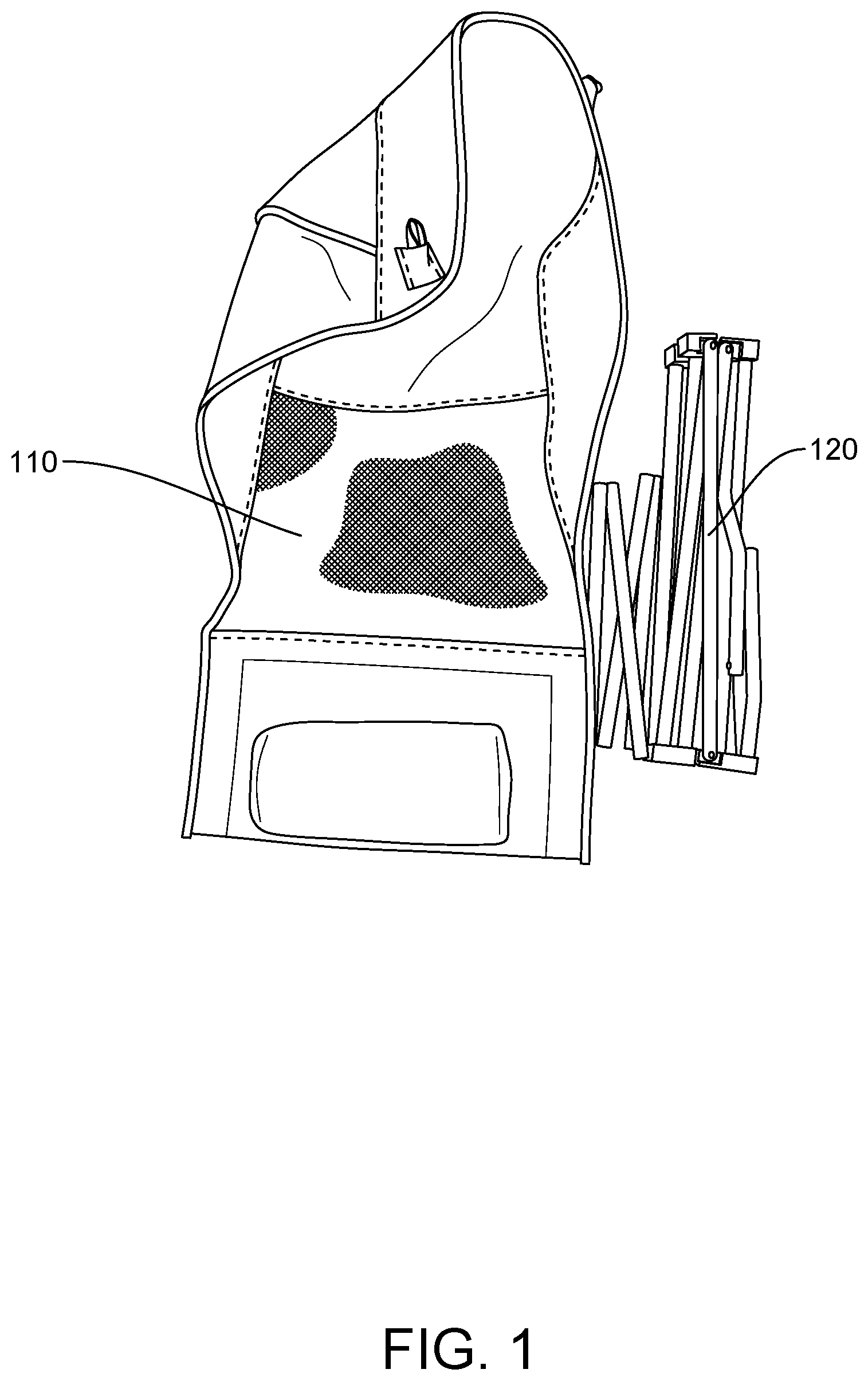
illustrates a schematic view of the fabric and chair frame that have not been assembled as a chair in accordance with one embodiment of the present invention.
illustrates a schematic view of the chair frame in the present invention when it is totally collapsed.
illustrates a schematic view of the chair frame in the present invention when it is partially collapsed.
illustrates a schematic view of the chair frame in the present invention when it is in the extended configuration.
illustrates a partially enlarged view of the first front supporting rods.
A illustrates a perspective view of a foldable chair incorporating the foldable support base in accordance with one embodiment of the present invention; B is a front perspective view of the foldable support base of the foldable chair without the fabric seat; C is a front view of the foldable support base; D is a perspective view of the foldable support base.
A to 7 C are views corresponding to the views of A to 6 C for comparisons, wherein A illustrates a perspective view of a foldable swing chair incorporating the foldable support base in accordance with another embodiment of the present invention; B is a front perspective view of the foldable support base of the foldable swing chair without the fabric seat; C is a front view of the foldable support base for the swing chair in a partially collapsed configuration.
A to 8 C are views corresponding to the views of A to 6 C and A to 7 C for comparisons, wherein A illustrates a perspective view of a foldable hammock incorporating the foldable support base in accordance with another embodiment of the present invention; B is a front perspective view of the foldable support base of the foldable hammock without the hammock bed; C is a front view of the foldable support base for the foldable hammock in a partially collapsed configuration.
DETAILED DESCRIPTION OF THE INVENTION
The detailed description set forth below is intended as a description of the presently exemplary device provided in accordance with aspects of the present invention and is not intended to represent the only forms in which the present invention may be prepared or utilized. It is to be understood, rather, that the same or equivalent functions and components may be accomplished by different embodiments that are also intended to be encompassed within the spirit and scope of the invention.
Unless defined otherwise, all technical and scientific terms used herein have the same meaning as commonly understood to one of ordinary skill in the art to which this invention belongs. Although any methods, devices and materials similar or equivalent to those described can be used in the practice or testing of the invention, the exemplary methods, devices and materials are now described.
As used in the description herein and throughout the claims that follow, the meaning of “a”, “an”, and “the” includes reference to the plural unless the context clearly dictates otherwise. Also, as used in the description herein and throughout the claims that follow, the terms “comprise or comprising”, “include or including”, “have or having”, “contain or containing” and the like are to be understood to be open-ended, i.e., to mean including but not limited to. As used in the description herein and throughout the claims that follow, the meaning of “in” includes “in” and “on” unless the context clearly dictates otherwise.
It will be understood that, although the terms first, second, etc. may be used herein to describe various elements, these elements should not be limited by these terms. These terms are only used to distinguish one element from another. For example, a first element could be termed a second element, and, similarly, a second element could be termed a first element, without departing from the scope of the embodiments. As used herein, the term “and/or” includes any and all combinations of one or more of the associated listed items.
It will be understood that when an element is referred to as being “connected” or “coupled” to another element, it can be directly connected or coupled to the other element or intervening elements may be present. In contrast, when an element is referred to as being “directly connected” or “directly coupled” to another element, there are no intervening elements present.
The inventive support base can be deployed in various furniture with a flexible user support platform, which may be padded or unpadded, constructed using a flexible material, such as a web material made of a synthetic and/or natural fabric or cloth, canvas, a woven, sheet, mesh or netting material, etc. Hereinbelow, the flexible material for the flexible support platform may be generally referred to hereinbelow as a “fabric” without limiting to a particular type of flexible material.) The present invention will be disclosed below in reference to chairs and hammocks as exemplary embodiments of foldable furniture with a flexible user support platform incorporating the novel foldable/collapsible support base.
Prior to a detail discussion of the structure of the inventive foldable support base, it is beneficial to discuss a specific deployment of the inventive foldable support base in reference of a foldable chair having a flexible user support platform.
In one aspect, referring to to 6 , a foldable chair 100 may include a fabric 110 and a chair frame 120 . The chair frame 120 may include rear supporting rods ( 121 , 121 ′), first front supporting rods ( 122 , 122 ′), second front supporting rods ( 123 , 123 ′), and a supporting base 124 . In one embodiment, as shown in , each rear supporting rods ( 121 , 121 ′) may include a plurality of rear connecting rods that can be telescopically connected to form each rear supporting rod.
In one embodiment, the rear supporting rods ( 121 , 121 ′) extend upwards from a rear portion of the supporting base 124 , while the first front supporting rods ( 122 , 122 ′) extend from one side of a front portion of the supporting base 124 , and the second front supporting rods ( 123 , 123 ′) extend from the other side of the front portion of the supporting base 124 .
Similarly, one of the first front supporting rods 122 and one of the second front supporting rods 123 can be telescopically formed as shown in . The supporting base 124 has a plurality of base connecting rods forming substantially four sides of the supporting base 124 . Each side may include two base connecting rods forming a single scissor hinge structure pivotally interconnecting with each other and other base connecting rods on two nearby sides as shown in .
It is important to note that the chair structure can be more stable and strengthened when the first front supporting rods ( 122 , 122 ′) move away from each other in an extend configuration as shown in , as well as the second front supporting rods ( 123 , 123 ′). When the fabric 110 is put on the chair frame 120 , the first front supporting rods ( 122 , 122 ′) are disposed in a first pocket 111 of the fabric, while the second front supporting rods ( 123 , 123 ′) are disposed in a second pocket 112 . Due to tension in the fabric seat (e.g., from elasticity of the fabric), the elasticity of the fabric, the first front supporting rods ( 122 , 122 ′) can be further separated to extend from the inward pulling by the first pocket 111 , as well as the second front supporting rods ( 123 , 123 ′) in the second pocket 112 , so the entire chair structure can be strengthen and becomes more stable.
When the chair is in use, for example, a user is sitting on the fabric 110 , and under the weight of the fabric, the pockets ( 111 , 112 ) of the fabric pulls the ends of the first front supporting rods ( 122 , 122 ′) and the second front supporting rods ( 123 , 123 ′) inwards, thus applying an external force to bias the first and second front supporting rods to extend against the other parts of the support base, so the chair structure can be more strengthened and stable. In other words, when the chair is in use, the user's weight helps the chair reach its most stable status.
When the chair is not in use, it is easy to fold because the supporting rods ( 121 , 121 ′, 122 , 122 ′, 123 , 123 ′) are telescopically connected and they can be folded as shown in . Moreover, since the supporting base 124 is formed by two base connecting rods on each side with a single scissor hinge structure pivotally interconnecting with each other and other base connecting rods, the size of the supporting base 124 can also be easily minimized as shown in .
With the foregoing discussion in reference to a foldable chair as background, the inventive concept of the foldable support base of the present invention will be explained in greater detail below, in reference to terminologies consistent with the claims to be presented. The following discussions further elaborate on the structure of the foldable support base for the foldable chair in the embodiment discussed above, followed by discussions of the structure of additional embodiments directed a foldable swing chair ( A- 7 C ) and a foldable hammock ( A- 8 C ) incorporating the inventive foldable support base. These embodiments highlight the base inventive concept, as the foldable support bases for the foldable chair, foldable swing chair and foldable hammock are substantially similar with some variations consistent with the respective embodiments.
Referring to A to 6 D (without flexible user support platform, or in this case a seat fabric, remove), the present invention is directed a foldable support base SB 1 for a foldable furniture with a flexible user support platform, comprising a first support frame SF 1 and a supplemental support frame SSF 1 coupled to the first support frame SF 1 to complete the foldable support base. In the embodiment of D , the first support frame SF 1 corresponds to a support frame at the front of the chair, and the supplemental support frame SSF 1 corresponds to the rest of the support base behind the front of the first support frame SF 1 .
The first support frame SF 1 comprises a first load member LM 1 at one side; a first side frame member SFM 1 pivotally connected to the first load member LM 1 , wherein a top portion of the first side frame member SFM 1 is pivotally connected to a first load pivot joint LPJ 1 along the first load member LM 1 , and wherein a first load section LS 1 of the first load member LM 1 extends beyond the first load pivot joint LPJ 1 , which is pivotable about the first load pivot joint LPJ 1 towards a center of the first support frame SF 1 . On the other side of the first support frame SF 1 , there is mirror image of the structure on the side discussed above, namely, a second load member LM 2 ; a second side frame member SFM 2 pivotally connected to the second load member LM 2 . A top portion of the second side frame member SFM 2 is pivotally connected to a second load pivot joint LPJ 2 along the second load member LM 2 . A second load section LS 2 of the second load member LM 2 extends beyond the second load pivot joint LPJ 2 , which is pivotable about the second load pivot joint LPJ 2 towards a center of the first support frame SF 1 . A first collapsible connecting frame CCF 1 is pivotally connected at a first side to a proximate end of the first load member LM 1 and the first side frame member SFM 1 , and pivotally connected at a second side to a proximate end of the second load member LM 2 and the second side frame member SFM 2 . The first collapsible connecting frame CCF 1 can be configured between an extended configuration in which the first and second side frame members SFM 1 and SFM 2 are spread to spaced apart from each other (see also ) and a collapsed configuration in which the first side frame member SFM 1 is brought close to the second side frame member SFM 1 (see also , 2 and 3 ).
The first and second load sections LS 1 and LS 2 of the first and second load members LM 1 and LM 2 are configured for removably attaching a flexible user support platform SP 1 (see also fabric 110 in A therebetween. A load on the flexible user support platform SP 1 would result in a force component pulling on the load sections LS 1 and LS 2 of the first and second load members LM 1 and LM 2 to cause the first and second load members LM 1 and LM 2 to pivot about the respective first and second load pivot joints LPJ 1 and LPJ 2 in a direction towards the flexible user support platform SP 1 , thereby biasing the first collapsible connecting frame CCF 1 to keep the first and second side frame members SFM 1 and SFM 2 to be spaced apart to maintain the first collapsible connecting frame CCF 1 in the extended configuration shown in B and 6 D .
The first collapsible connecting frame CCF 1 comprises a first scissor hinge structure X 1 pivotally interconnecting between the proximate end of the first load member LM 1 and a bottom portion of the first side frame member SFM 1 at the first side, and the proximate end of the second load member LM 2 and a bottom portion of the second side frame member SFM 2 at the second side. In this embodiment, the first scissor hinge structure X 1 comprises a single scissor hinge comprising a first connecting member CM 1 and a second connecting member CM 2 , wherein the first and second connecting members CM 1 and CM 2 are pivotally connected to each other at a substantially pivotal center of the first scissor hinge structure X 1 . A first end of the first connecting member CM 1 is pivotally connected to the proximate end of the first load member LM 1 , and a second end of the first connecting member CM 1 is pivotally connected to the lower portion of the second side frame member SFM 2 , and a first end of the second connecting member CM 2 is pivotally connected to the proximate end of the second load member LM 2 , and a second end pivotally connected to the lower portion of the first side frame member SFM 1 .
As shown in D , the supplemental support frame SSF 1 comprises a plurality of frame members pivotally coupled to the first collapsible connecting frame CCF 1 . In this embodiment, the supplemental support frame SSF 1 comprises: a second support frame SF 2 ; and an interconnecting frame pivotally interconnecting between the first support frame SF 1 and the second support frame SF 2 . The second scissor hinge structure X 2 comprises a third connecting member CM 3 and a fourth connecting member CM 4 , wherein the third and fourth connecting members CM 3 and CM 4 are pivotally connected to each other at a substantially pivotal center of the second scissor hinge structure X 2 . A first end of the third connecting member CM 3 is pivotally and slidably coupled to a third side frame member SFM 3 , and a second end of the third connecting member CM 3 is pivotally connected to the lower portion of a fourth side frame member SFM 4 . A first end of the fourth connecting member CM 4 is pivotally and slidably coupled to the fourth side frame member SFM 4 , and a second end of the fourth connecting member CM 4 is pivotally connected to the lower portion of the third side frame member SFM 3 . The slidable couplings by means of slidable pivot blocks B 1 and B 2 to slide up and down the third and fourth side frame members SFM 3 and SFM 4 , when transitioning between the extended and collapsed configurations of the support base SB 1 . It is noted that the rear second support frame SF 2 need not include load members, as the front of the flexible support platform SP 1 takes up more of the weight of the user sitting on the platform SP 1 .
The interconnecting frame comprises a pair of supplemental collapsible connecting frames SCCF 1 and SCCF 2 respectively pivotally connected at a first side to the first support frame SF 1 and at a second side to the second support frame SF 2 . The pair of supplemental collapsible connecting frames SCCF 1 and SCCF 2 can be configured between an extended configuration in which the first and second support frame SF 1 and SF 2 are spaced apart and a collapsed configuration in which the first support frame SF 1 is brought close to the second support frame SF 2 . Scissor hinge structures X 3 and X 4 are provided. The third scissor hinge structure X 3 pivotally connecting at its first side to the bottom portion of the first side frame member SFM 1 and the top portion of SFM 1 /the first end of the first connecting member CM 1 of the first scissor hinge structure X 1 , and pivotally connecting at its second side to the bottom portion of the third side frame member SFM 3 and the top portion of the SFM 3 /the first end of the third connecting member CM 3 (at the sliding block B 1 ) of the second scissor hinge structure X 2 . The fourth scissor hinge structure X 4 pivotally connecting at its first side to the bottom portion of the second side frame member SFM 2 and the top portion of the second side frame member SFM 2 /the first end of the second connecting member CM 2 of the first scissor structure X 1 , and pivotally connecting at its second side to the bottom portion of the fourth side frame member SFM 4 and pivotally connected to the second end of the fourth connection member CM 4 (at the sliding pivot block B 2 ) of the second scissor hinge structure X 2 .
The bottom of the scissor hinge structures X 1 , X 2 , X 3 and X 4 correspond to four of the support base SB 1 for resting on an external support surface, such as a ground.
Given the collapsible connecting frames CCF 1 and CCF 2 and supplemental collapsible connecting frames SCCF 1 and SCCF 2 , the entire support base SB 1 can be extended between a fully collapsed configuration shown in to a fully extended configuration shown in D (ready to be covered with the flexible support platform SP 1 ).
Referring also to (which depicts the second side frame member SFM 2 region, which is a mirror image of the first side frame member SFM 1 region), the first end of the first connecting member CM 1 of the first scissor structure X 1 is pivotally connected to the proximate end of the first load member LM 1 by a locking pivot member LPM structured to snap tightly to latch onto a first side frame member SFM 1 . Referring to C , in a partially extended configuration between the fully extended configuration and the collapsed configuration of the support base SB 1 , pivotal connections of the first side frame member SFM 1 , first load member LM 1 , the first connection member CM 1 and the second connecting member CM 2 are linkages resulting in a structure corresponding to a quadrilateral. Referring to B , in the fully extended configuration under the load on the flexible user support platform SP 1 , the first load section LS 1 of the first load member LM 1 pivots towards the center of the support base SB to press the locking pivot member LPM against the first side frame member SFM 1 to lock against the first side frame member SFM 1 , thereby reducing a linkage to result in remaining linkages CM 1 , CM 2 and SFM 1 in a triangular structure corresponding to a simple support truss structure, which is a sturdy and strong support structure. The same truss structure is also present at the side of the second side frame member SFM 2 and load member LM 2 .
A to 7 C are views corresponding to the views of A to 6 C for comparisons, wherein A illustrates a perspective view of a foldable swing chair incorporating the foldable support base in accordance with another embodiment of the present invention; B is a front perspective view of the foldable support base of the foldable swing chair without the fabric seat; C is a front view of the foldable support base for the swing chair in a partially collapsed configuration. As can be seen by comparison of the foldable swing chair embodiment in to the foldable chair embodiment in , the basic support frame SF in the support base SB 2 is very similar to the basic support frame SF 1 in the support base SB 1 . Only the differences between the two embodiments will be mentioned below. Components corresponding to the first support frame SF 1 in the previous embodiment are similarly labeled in the support base SB 2 in .
In this embodiment, the foldable support base SB 2 has only a single support frame SF, which is very similar to the first support frame SF 1 in . In this embodiment, the relative sizes of the frame members are different from that in the first support frame SF 1 in , but the overall mechanical structure is quite similar. The support frame SF is support by a supplemental support frame SSF 2 , comprising pivotally connected members on either side of the support frame SF. The flexible support platform SP 2 is a seat in the form of a flexible bucket having a rigid seating bottom. Its two sides are hung from the top of the load sections LS 1 and LS 2 of the load members LM 1 and LM 2 . The load sections LS 1 and LS 2 of the load members LM 1 and LM 2 in this embodiment are longer than the load sections and load members in the previous embodiment, as they directly support the load of a user sitting on the swing chair.
The supplemental support frame SSP 2 includes a first support leg frame SLF 1 supporting the first side frame member SFM 1 , and a second support leg frame SLF 2 supporting the second side frame member SFM 2 . The first support leg frame SLF 1 comprises a first set of first and second leg frame members LFM 1 and LFM 2 extending from each side of the first side frame member SFM 1 , and the second support leg frame comprises a second set of leg frame members LFM 3 and LFM 4 extending from each side of the second side frame member SFM 2 .
The first end of the first connecting member CM 1 of the scissor structure X is pivotally connected to the proximate end of the first load member LM 1 by a locking pivot member LPM structured to snap tightly to latch onto a first side frame member SFM 1 . In this embodiment, given the single support frame SF, the locking pivot member LPM also structured to snap tightly to latch onto the first load member LM 1 . Referring to C , in a partially extended configuration between the fully extended configuration and the collapsed configuration of the support base SB 2 , pivotal connections of the first side frame member SFM 1 , first load member LM 1 , the first connection member CM 1 and the second connecting member CM 2 are linkages resulting in a structure corresponding to a quadrilateral. Referring to B , in the fully extended configuration under the load on the flexible user support platform SP 2 , the first load section LS 1 of the first load member LM 1 pivots towards the center of the support base SB 2 to press the locking pivot member LPM against the first side frame member SFM 1 to lock against the first side frame member SFM 1 , thereby reducing a linkage to result in remaining linkages CM 1 , CM 2 and SFM 1 in a triangular structure corresponding to a simple support truss structure, which is a sturdy and strong support structure. The same truss structure is also present at the side of the second side frame member SFM 2 and load member LM 2 .
A to 8 C are views corresponding to the views of A to 6 C and A to 7 C for comparisons, wherein A illustrates a perspective view of a foldable hammock incorporating the foldable support base in accordance with another embodiment of the present invention; B is a front perspective view of the foldable support base of the foldable hammock without the hammock bed; C is a front view of the foldable support base for the foldable hammock in a partially collapsed configuration. As can be seen by comparison of the foldable hammock embodiment in to the foldable chair embodiment in and foldable swing chair embodiment in , the base support frame SF 1 and SF 2 in the support base SB 3 is very similar to that in the support frame SF 1 and SF 2 , except for the slidable coupling to the third and fourth side frame members and the presence of load members in the support frame SF 2 . Only the differences from the embodiment of will be mentioned below. Components corresponding to the first support frame SF 1 in the previous embodiment are similarly labeled in the support base SB 3 in .
In this embodiment, the relative sizes of the frame members are different from that in the first support frame SF 1 in , but the overall mechanical structure is quite similar. Unlike the previous embodiments, the hammock support base SB 3 has a pair of support frames SF 1 and SF 2 , which are structurally similar (i.e., mirror image of each other). The supplemental support frame SSF 3 comprises the second support frame SF 2 , which comprises a structure similar to the first support frame SF 1 ; and an interconnecting frame interconnecting between the first support frame SF 1 and the second support frame SF 2 . Given the pair of support frames SF 1 and SF 2 are structurally similar, only the features of the first support frame SF 1 of the support base SB 3 will be discussed herein. It is understood that the same structures are present in the support frame SP 2 . The flexible support platform SP 3 is longitudinal soft bed having its two ends are hung from the top of the load sections LS 1 and LS 2 of the load members LM 1 and LM 2 of the support frame SF 1 . The load sections LS 1 and LS 2 of the load members LM 1 and LM 2 in this embodiment are longer than the load sections and load members in the previous embodiment of , as they directly support the load of a user laying down on the hammock bed.
The corresponding components are similarly labeled on the first support frame SP 1 (and also second support frame SP 2 ). The second support frame SF 2 comprises: a third load member; a third side frame member pivotally connected to the third load member, wherein a top portion of the third side frame member is pivotally connected to a third load pivot joint along the third load member, and wherein a third load section of the third load member extends beyond the third load pivot joint, which is pivotable about the third load pivot joint towards a center of the second support frame; a fourth load member; a fourth side frame member pivotally connected to the fourth load member, wherein a top portion of the fourth side frame member is pivotally connected to a fourth load pivot joint along the fourth load member, and wherein a fourth load section of the fourth load member extends beyond the fourth load pivot joint, which is pivotable about the first load pivot joint towards a center of the second support frame; and a second collapsible connecting frame pivotally connected at a first side to a proximate end of the third load member and the third side frame member, and pivotally connected at a second side to a proximate end of the fourth load member and the fourth side frame member, wherein the pair of connecting frame members can be configured between an extended configuration in which the third and fourth side frame members are spread to be spaced apart from each other and a collapsed configuration in which the third side frame member is brought close to the fourth side frame member, wherein the third and fourth load sections of the third and fourth load members are configured to further removably attach the flexible user support platform therebetween, and wherein a load on the flexible user support platform results in a force component pulling on the load sections of the third and fourth load members to cause the third and fourth load members to pivot about the respective third and fourth load pivot joints in a direction towards the flexible user support platform, thereby biasing the second collapsible connecting frame to keep the third and fourth side frame members to be spaced apart to maintain the second collapsible connecting frame in the extended configuration. (Herein, for the second support frame SF 2 , the ‘third’ components correspond to respective “first” components, and “fourth” components correspond to respective “second” components.)
The interconnecting frame comprises a pair of supplemental collapsible connecting frames SCCF 1 and SCCF 2 respectively pivotally connected at a first side to the first support frame SF 1 and at a second side to the second support frame SF 2 , and wherein the pair of supplemental collapsible connecting frames SCCF 1 and SCCF 2 can be configured between an extended configuration in which the first and second support frame SF 1 and SF 2 are spaced apart and a collapsed configuration in which the first support frame SF 1 is brought close to the second support frame SF 2 .
The pair of supplemental collapsible connecting frames comprises: a third scissor hinge structure pivotally connecting at its first side to the bottom portion of the first side frame member and the proximate end of the first load member, and pivotally connecting at its second side to the bottom portion of the third side frame member and the proximate end of the third load member; and fourth scissor hinge structure pivotally connecting at its first side to the bottom portion of the second side frame member and the proximate end of the second load member, and pivotally connecting at its second side to the bottom portion of the fourth side frame member and the proximate end of the fourth load member.
Accordingly, unlike the embodiment in , the third scissor hinge structure X 3 pivotally connects at its second side to the bottom portion of the third side frame member and the proximate end of the third load member instead of the first end of the third connecting member of the second scissor hinge structure. Further, the fourth scissor hinge structure X 4 pivotally connects at its second side to the bottom portion of the fourth side frame member and the proximate end of the fourth load member instead of the end of the fourth connection member. Similar structural differences for the other components mirror the above. In another aspect, the present invention is directed to a foldable furniture for supporting a user for resting, comprising: a foldable support base as described herein; and a flexible user support platform removably attached to the first and second load sections of the first and second load members of the foldable support base.
In this embodiment, referring to A and 8 B the first end of the first connecting member of the first scissor structure X 1 is pivotally connected to the proximate end of the first load member with an overlapping region O between the first end of the first connecting member CM 1 and the proximate end of the first load member LM 1 when the first load member LM 1 is pivoted to be parallel to the first connection member CM 1 , wherein in the extended configuration under the load on the flexible user support platform, the first load member pivots to press a side of the first end of the first connecting member CM 1 against a side of the proximate end of the first load member LM 1 to be parallel in the overlapping region O, thereby reducing a linkage to result in remaining linkages in a triangular structure corresponding to a simple support truss structure.
More specifically, a locking member LKM, having a snap configuration similar to the previous embodiments, is attached at one of the proximate end of the first load member LM 1 or the end of the first connecting member CM 1 , which is configured to snap tightly to latch onto the other member (CM 1 or LM 1 as the case may be). Referring to C , in a partially extended configuration between the fully extended configuration and the collapsed configuration of the support base SB 3 , pivotal connections of the first side frame member SFM 1 , first load member LM 1 , the first connection member CM 1 and the second connecting member CM 2 are linkages resulting in a structure corresponding to a quadrilateral. Referring to B , in the fully extended configuration under the load on the flexible user support platform SP 3 , the first load section LS 1 of the first load member LM 1 pivots towards the center of the support base SB 3 to press a side of the first end of the first connecting member CM 1 against a side of the proximate end of the first load member LM 1 to be parallel in the overlapping region O, thereby reducing a linkage to result in remaining linkages CM 1 /LM 1 (one became an extension of the other or combined in a single linkage), CM 2 and SFM 1 in a triangular structure corresponding to a simple support truss structure, which is a sturdy and strong support structure. The same truss structure is also present at the side of the second side frame member SFM 2 and load member LM 2 .
In all the above embodiments, to collapse the support bases (SB 1 , SB 2 , SB 3 ), one can press down on the load sections LS of the respective load members M, the load sections LS are then pivoted/rotated in a direction away from the center of the support base, thus leveraging to release against the latch created by the locking pivot joints LPJ, the locking pivot members LPM or the locking members LKM to collapse the support bases into their collapsed configuration.
While the invention has been particularly shown and described with reference to the preferred embodiments, it will be understood by those skilled in the art that various changes in form and detail may be made without departing from the spirit, scope, and teaching of the invention. Accordingly, the disclosed invention is to be considered merely as illustrative and limited in scope only as specified in the appended claims.
Figures (15)
Citations
This patent cites (8)
- US1231686
- US7996935
- US10631648
- US10660443
- US10758048
- US11096493
- US11330906
- US20190290007